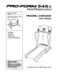
1
PRO.FORM 7 4 5 C S
Model No. 831.299473
Serial No.
USER'S MANUAL
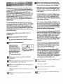
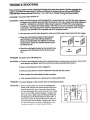
Find the seriaJn_'nber in the location
shown below. Write the serial number
in the space above for reference.
Serial
Number
Decal
_"X
_-- R C
EQUIPMENT
|ol
Ii
=!-'!11
i S
Ilol
i_
_ !,,1
HELPLINI=-I
1-800-736-6879
SEARS, ROEBUCK AND CO.
HOFFMAN ESTATES, IL 60179
Patent Pending
.CAUTION
Read all precautions
and instruc-
tions in this manual before using
this equipmenL
Save this manual
for future reference
www.proform.com
new products,
fltne_;s
tlf)q
,3nd
prizes
rllllch
i110I,
"_
PRO.FORM 7 4 5 0 S
TABLE OF CONTENTS
IMPORTANT PRECAUTIONS .................................................................
BEFORE YOU BEGIN .......................................................................
ASSEMBLY ..............................................................................
•
OPERATION AND ADJUSTMENT
.............................................................
HOW TO FOLD AND MOVE THE TREADMILL
.................................................
TROUBLE-SHOOTING
..........
°o
*
.°
• • °*
• *=o
• • * oo
• o = °.°°
o..._o°o
OONDmONING
GUIDELINES ..............................................................
PARTUST.
...................................................................
..
..
-- -•
ORDERING REPLACEMENT PARTS ..................................................
FULL 90-DAY WARRANTY ...........................................................
Note: An EXPLODED DRAWING is attached in the center of this manual.
o°.
°°.°_°.°°
,
.
°.°.°..o°_.
3
5
6
9
`20
,22
.24
.27
Back Cover
Back Cover
IMPORTANT
PRECAUTIONS
2.': Use the tre'adm[ll
3. (_Pla
tim power cord into a surge suppressor
(not included)
and p(ug the surge suppressor
hi)to a grounded circuit capable of carr_,'mg 15
or more amps. t_o other applxance should be
pitt
9
ofll_'lO
_,]if_e
clrctlil
Do
flO_ use
ai'l
e_l_,[i51Oll
cord
I I
l|,,e
oIlly
_,,lJl
,_ "_u]gh' _ulth't
I 11')
h,,b,d,v,,t
,ttlll)r_',,',_,_
_l_l]
Irll]
(iV'-,%)
,t h _',,
_,_II
,I 111
i
I,
surge
Ir,la_stel]l
]he
i
thal
19 Do not Cll.'_ngethe mchr_' of the treadmill by
IiI,IClrI¢
l obie¢
voll.,tg_'',o_cp'
I'.u_.i_,r lh_' lrl.admll]
_,ttrgesuppre,,'_or
',_lt)i)[_",',e(J
i[i,]
stlpl)re,mor
18. Do not attempt to raise, lower, or move the
treadmill untd _t_s_opedy assembled. (See
ASSEMI3LY on page 6, _d FIOWTO FOLD
AN D MOVE TI IE TREADMILL c_np_'ffje29.) You
I,_tnsl be at)_" |o s:dety |1|145 pounds
(_0 ks) in
order to ratse, lower, or n_ovethe treadrtl_L
Illil)l[l]lll[l
volt,l(le
r,Hil)_
(it_l_
II,
I ,_I
II
_l/)lt
,IJf,
II |011hill
tl,
_t [h,
I
I_l
h,r
II),J_/IIH
_'l'
I
ll,l'
! ,h P, ,
hi
Idlmll,
IqllJ¥
Ill,t;_'
f h_ ,f'_]
=oDAN G ER."_^way,u.oua.b,_,,_-:
cord Immediately nfter t_se before dean ng_
Jhe treadmlll,'an_] _fore perlo_lng
lhi_-i_'_.:-_
tenanee
nnd adjustment
procedures
_-;5,____-scr _ed n this manual, Never[emove
the'_:-a.
motor hood unless instructed
todo so bye'y]
author]ized service representative.
Servicing.
other than the procedures In thts manual_. / -.
should be _eriorn]ed by*an aulho'rized s_rvice"
reF.
:°_:q •
3r:
assume.?,no re.sic
of thls product'
SAVSTHESE
INSTRUCTIONS
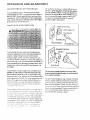
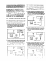
The decals shown below have been placed on your treadmill.
please call our toll-free HELPLINE to order a free replacement
Apply the decal in the location shown•
If a decal Is missing, or if it is not legible,
decal (see the front cover of this manual)•
, CAUTION
F_ i l' }I,_Hil
,[
_I
Z
[ ,
'
_' At'at) i i i I _'_W;_Y
I
I
I _ r
.
BEFORE
YOU BEGIN
---------
Thank you for selecting the revolufioua=yPROFORM"
745CS treadmill. The 745CS treadmill combinesadvanced technology with innovative design to help you
get the most from your exercise programin the convenienca and privacy of your home. And when you're not
exercising, the unique 745CS can be folded up; requiring less than half the floor space of other beadrr_.
Monday throughSaturday, 7 a.m. until7 p.m. Central
Tzme (exdm:Fmgha_days).To help us assist you,
pluase nofe the productmodel numb_ and serial num_
betrbefore _
The model number of the treadmill
is 831.299473. The serial number can be found on a
decal attached to Ize treadmill (see the front cover of
this manual for the Iocalion).
For your benefit, read this manual carefully before
using the treadmill. If you have add_
questions,
please call our toll-free HELPLINE at 1-800-736-6879,
Before reading ludher, please reviewthe drawing
below and famirmdzeyourself with the parts that are
labeled.
Water Bottle
Holder (Bottle
not included)
Pulse Sensor
Lock Knob
LEFT SIDE
Circuit
Breaker
Walking Belt
Foot
Power Cord
Front
Wheel
Rear Roller
Adjustment Bolts
Cushioned Walking Platform
ASSEMBLY
Assembly requires two people. Set the treadmill in a cleared area and remove all packing materials. Do not
dispose of the packing'materials until assembly is completed. Assembly requires your own Phillips screwdriver (]_====_
and rubber mallet c=:_:_.
Note: Theunderside of the treadmill walking belt is coated with high-pedormanoe lubricanL During shipping, a
small amount of lubricant may be transferred to the top of the walking bell or the shipping carton. This is a normal
condition and does not affect treadmill performance. If there is lubricant on top of the walking belt, simply wipe off
the lubricant with a soft cloth and a mild, non-abrasive cleaner.
1. With the help of a second person, carefully raise the
treadmill to the upright position.
While a second person tips the treadmill to one side
slightlyand holds it, Insed one of the Extension Legs (103)
into the treadmill as shown. Make sure that the Extension
Leg is tumed so the Base Pad (97) is on the bottom.
103
Next, tip the treadmill to the other side and insod the
other Extension Leg (not shown) in the same way. Lower
the side of the treadmill so that beth Extension Legs
(103) are resting flat on the floor.
97
2. With the help of a second person, carefully lower the
treadmill frame and then tip the Uprights (82) down as
shown. Make sure that the Extension Legs (103) remain In the Uprights.
Attach each Extension Leg (103) with two Screws (101)
and a Base Pad (119) as shown.
Note: One replacement Base Pad (119) and Spacer (not
shown) may be included, ff a Base Pad becomes worn
and needs to be replaced, use the replacement Base
Pad. If a Thisk Base Pad (97) needs to be replaced, use
the replacement Base Pad with the Spacer.
.119
,101
3. With the help o! a second person, carefully tip the
Uprights (82) back to the vedical position.
Attach the Latch Assembly (9) and the Latch Spacer (56)
to the left Upright (82) with two Screws (101) as shown.
3
4. Insert a Handra_ Extension (85) into the post on the left
Upright (82). Align the holes in the Handrail Extension
with the holes in the post. If necessary, tap the Handrail
Extension with a ndfear maUetto fuEyinsed iL Next,attach
the Handrail Extension by tightoningthree Small
(76) into the indicated holes. Note: If there is only one
hole in the top of the post, tighten the third .Sm_ll
Screw into the hole in the left side of the post.
4
Post
76
85
Cutout
110
Identify the Left Foam Gdp (110), which has a large
cutout in the right side. Sflde the Left Foam Gripas far as
possible onto the post on the leftUpright (82). It may be
helpful to apply soapy water to the Handrail Extension(85).
5. Make sure that the front edge of the Left Foam Gdp (110)
is under the Console Base (87) as shown. TKjhtena
Small Screw (76) Into the side of the Left Foam Gripas
shown. Note: You may need to pull on the side of the Left
Feam Grip to align the Small Screw with the hole in the
5
Up.hi (82).
Attach the Right Foam Gdp (not shown) and the other
Handrail Extension (not shown) as described in step 4
and this step.
Note: Extra screws may be Included.
6. Hold the treadmill firmly with both hands, and raise the
treadmill to the storage positionas described on page
20. If the latch pin does not align with the holein the
Catch (not shown), it will be necessary to remove the
Latch Spacer (56). Remove the two Screws (101), the
Latch Assembly (9), and the Latch Spacer. Re.attachthe
Latch Assembly with the two Screws. Make sure that the
latch pin engages the Catch.
6
_
9/
_Latch
Pin
v),)
101
i
7. Refer to drawing 7a. Locate the left Rear Foot (59) on
the treadmill. If the left Rear Foot touches the floor, go to
step 6. If there is a space between the left Rear Foot and
the floor, follow the instructions below.
7a
Hold the treadmill lirmly with both hands, and raise the
treadmill to the storage pos_on as described on page
20.
59
Refer to drawing 7b. Using a phillips screwdriver, remove
the Screw (60), the right Rear Foot (59), and the Rear
Foot Spacer (11) from the treadmill. Reaitach the dght
Rear Foot without the Rear Foot Spacer. Hold the treadmill w'rlhbeth hands, and lower the treadmill as
described on page 21.
Check the left Rear Foot (59 [see drawing 7a]). If the left
Rear Foot is still off the floor, raise the treadmill and remove the left Rear Fool Snap the Rear Foot Spacer (11)
onto the left Rear Foot and reettach the left Rear Foot
and the Rear Foot Spacer. Carefully lower the treadmill.
8. Make sure that all parts are tightened before you use the treadmill. Keep the included allen wrench in a
secure place. The allen wrench is used to adjust the walking belt (see page 23). To protect the floor or carpet
from damage, place a mat under the treadmill.
If you purchase the optional heart rate monitor (see
page 19), follow the steps below to Install the receiver Included with the heart rate monitor,
1
116
1. Make sure that the power cord Is unplugged. Remove
the six or seven indicated Screws (46) from the beck of
the Console Base (116).
2. Connect the Short Jumper Wire (A) to the wire on the
Receiver (B), Connect the other end of the Jumper Wire
to the PULSE jack on the back of the Console (see drawing 2b). Next, peel the paper off the pad on the back of
the Receiver. Turn the Receiver so the cylinder is on
the side shown, and press the Receiver into the bottom
of the Console Base (116) in the location indicated by the
dotted line. Note: A long jumper wire is included but wilt
not be used.
Make sure
that no wires
back ol the Console
step 1 above)
are pinched.
Reattach
Base (116) with the Screws
the
(46) (see
2a
/
116
2b
PULSE
Jack
OPERATION
]fiE
AND ADJUSTMENT
PERFO[iMANT
LUBE'"
WALKING
L]ELT
Your treadmill features a wa_r O belt coated with
VERFORMANT
LUBE '_, a high-pedormance
lut:_-mt.
IMPORTANT:
Never apply silicone
spray or other
substances
to the walking
belt or the walkir_
platform. Such substances
will deteriorate
the wa,lklng
belt and cause excessive
wear.
HOW TO PLUG
IN THE POWER
lhis prodLK.l _, for U_ orl a rK)n_nal 120 ,_ cUcuil.
and I_a_ a 9rourvJing I:_Y_jU_atlooks F_kel_e plug illu _
trated in dra_',_ 9 l below. A |empora_ a_
that
looks like tim adap_ Iastmted
in dra,w_n9 2 may b___
used to _
tl_ _urge s_
_o a 21:x)le
receptacle as _wn
in d_awir_g 2 if a rxof_fly
grounded _
is hal available.
CORD
Grouaded OulJet
6ro* f, ng
2
¢Jr- Grounded OutJetBox
Your treadmill, like any other type of sophisticated
electronic equipment, can be seriously damaged by
sudden voltage changes in your home's power.
Voltage surges, spikes, and noise interference can
result from weather conditions or from other appliances
being tumed on or off. To decrease the possibility of
your treadmill being damaged, always use a surge
suppressor with your treadmill (see drawing 1 at
the right).
To purchase a surge suppressor, see your local
SEARS or call toll-free 1-800-366-7278 and order
part number 146148. Use only a single-outlet surge
suppressor that is UL 1449 listed as a transient voltage
surge suppressor (TVSS). The surge suppressor must
have a UL suppressed voltage rating of 400 volts or
less and a minimum surge dissipation of 450 joules.
1he surge suppressor must be electrically rated for
120 volts AC and 1.5amim
This
product
must
tEorl or t)rL_k
t)e (Irotlrlded
dowrl,
[_.,tStL_f/(;_?
tot
elo_;trlC
Iftc shock
l tli_; pro(lu(:l
un ur_ulpru(_rll
plug
_nd
Plug
plug
(_utl_zl
,](
(
the
Jrill/_lll,HIt
, i
power
I , ,HH;,:,
1,
lhP
h
_]TJ
lJ_'
f ,,_th'T
into
Q cord
a grounding
a surge
ill!;I;dh,(l
;Hid
i<]iIHtl
I',
rl,q
of e1(%
wilh
into
('t)_{,%
lh( _. risk
and
suppret;sor
I()(:,]I
m31ftJrl(:
a p_th el k_a_i[
r(X_UC_
corld_Jctor
t)rol)(!rly
t+'Jlt
t()
_:; _{luipI>t!d
cord
surge
th_It it;
()[(J,ill(
provi(Jt_s
c_lrr{!flt
groulldillg
tile
!l i1 shoul(J
grolJrl(Jillg
;_r}(|
I'_vtrlg
suppressor,
,an appropri,lle
grourl(l(!(J
irl
or(fill;ill(
( iH11p,l{ll)l¢,
1,%
with
.Adapter
_e_
_L
Aria"
,SurgeSuppressor
The temppranj adapler sho_k] be used only unLqa
property grourK_d oe6et (drawing 1) can be i_staJ_ed
by a qualified
The green-cok)red dgid ear, lug, or the like extending
from the adapter must be connected Io a permanent
ground sucb as a properly grounded outlet box cover.
Whenever tbe adapter is used it must be held in place
by _tmetal screw. Some 2-pole receptacle outlet box
covers are not grounded. Contact a qualified electrician to determine it the outlet box cover is
grounded before usir_g an adapter.
CONSOLE
DIAGRAM
Incline Display
Displays
__
I [ D l rack
-----
::
l)ist)lay:,
:
@)@
*_1
Manual/iFIT.com
Indicators
I'r(_)ram Indicators
@)@
v¢
___
Note: 1t there is a thin sheet of clear plastic
on the face of the console, remove it.
Speed Buttons
Key '__-'_1_]_--
Clip
home stereo, portable stereo, or computer and play
special iFIT.com CD programs (one CD is provided).
IFIT.eom CD programs automatically control the speed
and incline of the treadmill as a personal trainer guides
you through every step of your workouL High-energy
music provides added motivation. Each CD features
two different programs designed by codified personal
trainers.
In addition, you can connect the treadmill to your VCR
and TV and play iFIT.com video programs (videocassettes are available separately). Video programs offer
the same benefits as iFfT.com CD programs, but add
the excitement of working out with a class and an instructor-the
hottest new trend at health clubs.
FEATURES OFTHE
CONSOLE
The treadmill console offers an impressive array of
features to help you get the most from your exercise
When the console is in the manual mode, the speed
and incline of the treadmill can t)o controlled with ;_
i()LJ(:HL)[a hulton. As yell exorcme, the l El) track {ll/tJ
Ihe tour displays will provide co[Itinuou5 exercise Iced
back
You
can
ever
measure
yoLIr
h(
;trt
rate
iJ,%irl_t
lh()
t)uill Lr)pulst, sensor
._ix (:ertified
t a(:h
port_orlal
)r(xfram
l[aillo[
au (_r
chrlt! el the lrt';l(_rlttll
llw, w()r kot jl
Ieally
progr:tm'J
corllroh;
ate, al,.;<) offttH,d
the! _;t)t!_'(I
a', it _]uId_'_, ¥()LI [h_tJqh
arid
;Ill
irl
_'fh'_
With the treadmill connected to your computer, you
can also go to our new intemet site at www.iFIT.com
and access even more programs. Choose from a selection of basic programs that interactively control the
speed and incline of your treadmill to help you achieve
your personal exercise goals. Or, use iFll corn audio
and video programs directly from our inlemnt site Visit
www.iFIT corr_ tot complete d(_Iai!s
l_y _ldthr/g _lrl opte<)tl_ll HH!]ra(h' rHodH[P h)the' hu.i{hnfll
you caq LIt;O virtually endless l_xlturos frorn eli[ irllornol
sii_ See www iFI [ r:om to learn atx)_d oth_r iF] l COnl
leaturo_; To purchaseiFIT.comCD's,
iFIf.com
videocassettes,
or an optional
upgrade module,
see your local SEARS or call loll-free
1-800 884
0620. For informalion
about other optional
acces
t_oriotL s_(" l);l(](! 19
Ti.) tl%p
I Hi,
(:()[1_()11_
,]!',l/
]f';!TIIII,',
;t!]v;]rl(
_1_
I}
] _
_ (}fll
I[ll+'l
b
',T*
fr
II ",
,rr,
It1_,
II],IIIH,II
l_d '(ILZltlJtlr
,
,jl
i,it.
Ill//d_'
I _llb
,
I_
•
I,]_'
()!
I
I
U H' ( *)f;_,[I]l'
[{)
LI',("
,_
p_r
h ql, _,',' Ill,
%_,)r1,11
Ir4111_'l
HOW TO TURN ON THE POWER
g
change Ibe speed of the
walking bellas desired by
pressinglie SPEED A
and V bull0ns.To change
Plug in
the power
cord
(see
HOWTO
PLUG IN
THE
POWER
CORD
on
page
9)_
thespeedsetting
quidUy.
B
switch on the front of
the treadmill. Make
sure
thethe
on/off
switch
Locate
on/on
I
press the QUICK SPEED
buttons.Nolle:After the buttons are pressed, it
may take a moment lot"the treadnullto reach the
setec_ed speed setting.
On
Position [_
is in the on pesition.
To stop Ihe wa_
belt, press the STOP button.
The TIME dcsplayvail begin to flaSlL To restart the
walking bell wess the START button or the
SPEED A button.
k3
Stand on the foot rails
of the treadmill. Find
the clip attached to the
key, and slide the clip
securely onto the waistbend of your clothing.
Test the clip by carefully taking a few steps backward until the key
Is pulled from the console. If the key is not
pulled from the console, adjust the pesiSon of
the clip as needed.
B
To change the
incline o_
treading,mese
_l_i_31--e
e
e o O O _z 3
the INCt.ll_
bettons. Each
time a bel:10nis
pressed, the incline w_ change
Next, insert the key into the console.Aflera moment, the four displays, the LED traclq and various
indicators on the console will light.
by 0.5%. The buttons can be held down to change
the incline qu'_tdy.Note: After the incline buttons
are pressed,it willtake a moment for the treadmill
to reach _e selected incline setting.
Note: The console can display speed and distance in
either miles or kdlometers(see SPEED/MIN-MILE DISPLAY on page 12). For simplicity, all instructions in this
manual refer to miles.
Note: In the incline(f=splay,the first indicator will
light whe_ the incline is set at 1.5%. The second
indicator w_lr_ht when the incline is set at 2% or
2.5%, the thirdindicator will lightwhen the incline
MODE .........................................
is set at 3% or 3.5%, and se forth.
...._OW _;_SE._EMANUA_
_1
Cbenge the iner_e of the treadmill as desired.
Insert the key fully into the console.
B
Follow your progress with the LED track and
the four d_splays.
See HOW TO TURN ON THE POWER above.
The LED Track--The
B
Select the manual mode.
LED trackrepresentsa
distance_i 1/4 rn_e.As
When the key is inserted, the manual
mode will be selected
and the MANUAL indi-
you exerc_e, the indicators aroundthe track will
cator will light. If a program has been selected, press the PROGRAM button repeatedly to
select the manual mode.
mile. A new lap will then begin.
r,:jht one at a time until
you have completed 1/4
play--This
display shews
the distance that you
DISTANCE/LAPS
have
walked or run disand
B
Press the START button or the SPEED A button
to start the walking belt.
A moment
aller
bell
will beg*n
;!lid
c;]r_fHllyt)edill
the
button
to move
is pressed,
at 1 mph
tlold
lhe walking
the handfads
w;]qklrq_ 1 Aq y_),_,_,.cci,;,_
the number of laps you
have completed (one lap
Arrow
l_J_
orsrA_c_
]/
13
II
_._PS
equals 114mile) The display will alternate between
one ntJmbe_ and the othe_ every seven seconds.
1
TIME display--When
the manual mode or an
iFIT.com program is
selected, this display
shews the elapsed time.
When a personal trainer
program is selected, this display shows both the
time remaining in the program and the time remaining in the current segment of the program.
The display Will alternate between one number and
the other every seven seconds.
CALS/FAT CALS/
PULSE display--This
display shows the approximate numbers of
ca/odes and fat calories
_
' Measure your heart rate, if desired.
Stand on the
foot rails and
place your
hands on the
metal Contacts
on the pulse bar.
Your palms
must be resting
on the confacts---avoid
moving your
hands. When
PULSE
your pulse is detected, the heart-
_ 12B 1
CALS.
FAT CALS.
B
display--This display
I-/-I
shows the speed of the
.._.IL_
walking belt and your
v
SPEED
MINI MILE (km)
current pace (pace is
measured in minutes per
mile). Every seven seconds, the display will
change from one number to the other, as shown
by the arrows in the display.
Note: The SPEED/MIN-MILE display can show
speed in either miles per hour or kilometers per
hour. To find which unit of measurement is selected, hold down the STOP button while inseding
the key into the console.
An "E" for English miles
or an "M" for metric kiloC"
meters will appear in the
display. Pressthe
SPEEDMINIMILEfkm)
SPEED A button to
change the unit of measurement. When the desired unit of measurement
is selected, remove and then reinsert the key.
Note: To reset the displays, press the STOP button, remove the key, and then reinsert the key.
- 123
FAT CAL$.
shaped indicator
--,._._.
in the CALS/FAT C/M_S/PULSE display willflash
steadily and a sedes of dashes (--) will appear.
After a few seconds, your heart rate will be shown.
For the most accurate heart rate reading, continue to hold the contacts for about 15 seconds.
you have burned (see
FAT BURNING on page
24). Every seven seconds, the display will change
from one number to the other, as shown by the arrows in the display. This display will also show
your heart rate when the pulse sensor Is used (see
step 6 on this page).
SPEED/MIN-MILE
SensoP3
When you are finished exercising, remove the
key.
Step onto the foot rails, press the STOP button,
and adjust the incline of the treadmillto the lowest
level. The incline must be at the lowest level
when the treadmill is raised to the storage position or the treadm|ll will be damaged. Next,
remove the key from the console and put the key
in a secure place. Note: If the displays and various indicators on the console remain lit after
the key is removed, the console is in the
"demo" mode. Refer to page 19 and turn off the
demo mode.
When you are finished using the treadm_l, move
the on/off swftch near the pewer cord to the off
position.
HflW
B
B
J] U
UbE_JPkH_UNAL_:!
HAINEH
:P]_
One speed sett_j and one incline setting are progrananed Ior each segment. Whon only three secondlsremainin the 6rst ,sec_nt, a sedes of tones
willsound and the treadmillwillautomatically ad_
]('-,_1 A M ."
Insert the key into the console.
justzoIve speedand indinesetZings
for thesecond
See HOW TO TURN ON THE POWER on page
11.
segma_
The Program willcontinue in this way until the
TIME display counts down to zero. The wagdog
belt will then slow to a stop.
_lect one of the personal trainer programs.
When the
key is in-
Note: If the speed or incrlnesetting for the current
segment istoo high or ton low, you can manually
ovedide the settingby pressingthe SPEED or
INCLINE buttonsen the console. However, when
the next segment begins, the treadmill will adjust to the next speed and incrme settings of
the Program.
=..,_..,,,.,,, =,,,,...,,=
sealed, the
._-e --.,
manual
mode will be
selected and
the MANUAL indicator will lighL
To select one of the personal trainer programs,
press the PROGRAM button repeatedly untgone
of the so( personal trainer program ind'v:ators
lights.
The console features two low intensityprograms,
two medium intensity programs, and two high intensity programs. The profileson the console
show how the speed and incline of the treadmill
will change dudng the programs. The numbers
beside the profiles show the maximum speed and
incline settings for the programs. For example, the
upper profile shows that the treadmill wig reach a
maximum speed of 4.5 mph and a maximumincline of 5% dudng the first program.
B
Press the START button or the SPEED A button
to start the program.
A moment after the button is pressed, the treadmill will automatically adjust to the first speed and
incline settings for the program. Hold the handrails
and begin walking.
Each program is divided
into several time
segments of different
lengths. The TIME
display shows both the
time remaining in the program and lhe time
remaining in the current
segment
To stop the.Program, prees the STOP buttorL The
TllUlE(r_play willbegin to fla_ To restart the program,ixess the START buttcu orthe SPEED Z_
button.To end the program, press the STOP button, removeShekey,and then reinsert the key.
B
Fonow your Fogress with the LED track and
thefour pZa .
Refer to step5 on page 11.
[]Measure
your heart rate, if desired.
See step 6 on page 12.
r_Whon the program is completed, remove the
key frem the cousole.
When the programhas ended, make sure that
the trezKl,_ is at the lowest incline leveL Next,
remo_etha keytrom the console end put it in a
secureplace. Note: If the displays and indieatots on the console remain rd after the key is
removed, the console is in the "demo" mode.
Refer to page 19 and turn off the demo mode.
When you are finishedusingthe treadmill, move
the on/off switch near the power cord to the off
position.
of the program.
HOW TO CONNECT YOUR PORTABLE STEREO
To use IFIT.com CD's, the treadmill must be connected to your portable CD player, portable stereo,
home stereo, or computer with CO player. See pages
14 and 15 for connecting instructions. To use IFIT.com
v|deocassettes, the treadmill must be connected to
your VCR. See page 16 for connecting Insbucl_ons. To
use iFIT,com programs directly from our intemet
site, the treadmill must be connected to your home
computer. See page 15 for connecting instructions.
HOW TO CONNECT
Note: It your stereo has an RCA-type AUDIO OUT
jack, see instruction A below. If your stereo has a
3.5mm LINE OUT jack, see Instruction B. If your
stereo has only a PHONES jack, see instruction C.
A. Plug one end of the audio cable into the jack on the
front of the ti'eadmill near the power cord. Plug the
other end of the cable into the included a6apter. Plug
the adapter into an AUDIO OUT jack on your stereo.
A
YOUR PORTABLE CD PLAYER
Note: If your CD player has separate UNE OUT and
PHONES jacks, see Instruction A below. If your CD
player has only one Jack, see instruction B.
AudAd Ie,4
{_
Cable
A. Plug one end of the audio cable into the jack on the
front of the treadmill near the power cord. Plug the
other end of the cable into the UNE OUT Jack on
your CD player. Plug your headphones
PHONES jack.
into the
B. Plug one end of the audio cable into the jack on the
tront of the treadmill near the power cord. Plug the
other end of the cable into the LINE OUT jack on
your stereo.
B
=' "
"_
i_
---':
(_q'_:
_
i
..
Auo_o
Cable
_
LU
_
Headphones
[]
('_;
"._[_i':
_ _
Audio
:"
,_-__
.-icY_-__,_L_
B. Plug one end of the audio cable into the jack on the
front of the treadmill near the power cord. Plug the
other end of the cable into a 3.Smm Y-adapter
(available at electronics stores). Plug the Y-adapter
into t.he PHONES jack on your CD player. Plug your
headphones into the ether side of the Y-adapter.
......
C. Plug one end of the audio cable into the jack on the
front of the treadmill near the power cord. Plug the
other end of the cable into a 3.5ram Y-adapter
(available at electronics stores). Plug the Y adapter
into the PHONES jack on your stereo. Plug your
headphones into the other side ol the Y-adapter.
3.Smm
:
:il_
i
(0 H_T_]] :
Cable
Audio
Cable
Y-adapter _
[(i 1]
,-; _TT-,I
Aud,o
Cat c.
Y ad;,,l)h'!,
:_ 5mrn
I
,/
t
)
HOW TO CONNECT YOUR HOME STEREO
HOW TO COI_IECr
Note: If your stereo has an unused UNE OUT jack,
see instruction A below. If the UNE OUT jack is
being used, see instruction B.
Note: If your €ompu_r has a 3.5ram UNE OUT jack,
see tnstxucSo, A. II your computer has only a
PHONES jack, see Imlmcti_ B.
A. Plug one end of the audio cable into the jack on the
front of the treadmill near the power cord. Plug the
Other end of the cable into the included adapter.
Plug the adapter into the LiNE OUT jack on your
stereo.
A. Plug one end ol Ihe aedio cable into the jack on the
fro_ of the lmadmil near the power co_l. Plug the
other end ol Ihe _01e intothe LINE OUT jack on
your compuler.
YOUR COMPUTER
A
[
_A
i
if.
CaUe
,,u,,o
Cable
B. Plug one end of the audio cable into the jack on the
front of the treadmill near the power cord. Plug the
other end of the cable into the included adapter.
Plug the adapter into an RCA adapter (available at
electronics stores). Next, remove the wire that is
currently plugged into the LINE OUT jack on your
stereo and plug the wire into the unused side of the
RCA adapter. Plug the RCA adapter into the LINE
OUT jack on your stereo.
B. Plug one _ of Ihe a .ucrlo
cable intothe jack on the
frontof thetreadml near the powei'cord. Plug the
other end ofthe cable intoa 3.5nvn Y-adapter
(available at eleclronicsstores).Plug the Y-adapter
intothe PHONES jack on yourcomputer.Plug your
headphones or speakersilito the otherside of the
Y-adapter.
B
lll
!B
_1_]
f_:-_-_-__,
's't__..._._._."
[]@
Aud,o
_[_
Cable
RCA
AdapteT-
Adapter
Wire removed from _[::::_,,_
LINE OUT jack
i
Cable
= Y-adapter
Headphones/Speakers
_-_
HOW
TO CONNECT
YOUR
VCR
Note: If your VCR has an unused AUDIO OUT jack,
see Instruction A below. If the AUDIO OUT jack is
being used, see Instruction B. If you have a "IV
with a built-In VCR, see Instruction
B. If your VCR
Is connected to your home stereo, see HOW TO
cONNECT YOUR HOME STEREO on page 15.
A. Plug one end of the audio cable into the jack on the
front of the treadmill near the power cord. Plug the
other end of the cable into the included adapter.
Plug the adapter into the AUDIO OUT jack on your
VCR.
A
YOUR CD PLAYER, VCR, OR COMPUTER on page
14. Note: To purchase IF1T.com CD's or to purchase IFIT.com vldeocassettes, see your local
SEARS or call toll-free 1-800-735-0768.
Follow the steps below to use an iFIT.com CD or
video. Note: The Instructions
Included in the CD
case describe how to use the CD with a variety of
PROFORM treadmills. Some Instructions ma_not
apply to this treadmill.
_.
m
|1
To use iFIT.com CD's or videocassettes, the treadmill
must be connected to _your portable CD player, portable
stereo, home stereo, computer with CD player, or
VCR. See HOW TO CONNECT THE TREADMILL TO
i
U
il'_
i@
@i
Audio
i
Adapter 4
Insert the key fully into the console.
See How TO TURN ON THE POWER on page
11.
Cable
_'_1 Press the PROGRAM button.
B. Plug one end of the audio cable into the jack on the
front of the treadmill near the power cord. Plug the
other end of the cable into the included adapter.
Plug the adapter into an RCA adapter (available at
electronics stores). Next, remove the wire that is
currently plugged into the AUDIO OUT jack on your
VCR and plug the wire into the unused side of the
RCA adapter. Plug the RCA adapter into the AUDIO
OUT jack on your VCR.
When the key is inserted, the manual
mode will be selected.
To use an iFIT.com CD
or video program, press
the PROGRAM button
repeatedly until the
iFIT.com indicator lights.
!_
Insert the IFIT.com CD or vldeocassette.
If you are using an iFrr.com CD, insert the CD
into your CD player. If you are using an iFIT.com
videocassette, insert the videocassette into your
VCR.
B
........i
,'
/
................."
RCA Adapter_!_
Wire removed from
AUDIO OUT jack
_
B
Press the PLAY button on your CD player or
VCR.
A momen! after the button is pressed, your personal
trainer will begin guiding you through your workout.
Simply follow your personal trainer's instructions.
Note: II the TIME display is flashing, press the
START button or the SPEED G button on the console. The treadmill will not respond to a CD or
video program when the TIME display is flashing.
OudngtheCOorvideoprogram,
an_
TIME display is _,
press the START
button or the SPEED A button on the console
"chirping" sound will alert you when the speed
and/or inclineof the treadmillis aboot to change.
CAUTION: Always listen for the "chirp" and be
prepared for speed and/or incline changes In
some instances, the speed and/or incline may
change before the personal trainer deacn'bes
the change.
- adjust the volumeof your CD player or VCR. If
the volume is too high or too low, the console
may not detec_I_e latxjram signals
- make sure that the audlo cable la properly
connected, thai it is Ikdlyplugged in, and that
it is not wrapped around a power cord
If the speed or incline settings are too high or too
low, you can manually overridethe settingsat any
time by pressing the SPEED or INCLINE buttons
on the console. However, when the next =chirp"
is heard, the speed and/or incline will change
to the next settings of the CD or video program.
To stop the program at any time, press the STOP
button on the console. The TIME display _'11begin
to flash. To restart the program, press the START
button orthe SPEED/_ button.After a moment,
the walking belt will begin to move at I mph`
When the next =chirp" is heard, the speed and
incline will change to the next settings of the
CD or video program. The program can also be
stopped by pressing the STOP button on your CD
player or VCR
When the CD or video program is completed, the
walking belt will stop and the TIME display will
begin to flash. Note: To use another CD or video
program, press the STOP button or remove the
key and go to step 1 on page 16.
Note: If the speed or incline of the treadmill
does not change when a "chirp" is heard:
• make sure that the iFIT.com indicator is lit and
that the TIME display is nct flashing. If the
• If you are using yourportable CD player and
the CD skips, set the CD player on the floor or
another flat surface _stead of on the console
]Follow
your progresswith the LED track and
the four displays
See step 5 on page 11
ro,_ Measure your heart rate, If desired
See step 6 on page 12.
B
When the iFIT.com CO or video program is
finished, remove the key.
See step 6 on page 13.
CAUTION: Always remove iFIT.eom CD's and
videocassettes fromyour CO player or VCR
when you are finished using them.
. _._,_,,_
_nw
,__,_p._:_,_._,_.i,._:'_i
_O USE PROGRAMS_IRECT!_YJ_:_F_OM_°:_
¸
=
_--_ Return to the treadmill and stand o_nthe foo_
rails. Find the clip attached to the key and slide
the clip onto the waistband of your clothing.
When the on-screen countdown ends, the program
will begin and the walking belt will begin to move.
Hold the handrails, step onto the walking belt, and
begin walking.
Our new intemet site at www.iFIT.com allows you to
access a large selection of programs that interactively
control your treadmill to help you achieve your specific
exercise goals. In add'align, you can play iFIT.com
audio and video programs directly from the intemeL By
adding an optional upgrade module to the console, you
can use vidually endless features on our intemet site.
Explore www.iFIT.com for details. To purchase an up
grade module, see your local SEARS or call toll-free 1 800-735-0768.
During the program, an electronic"d'tiq:k_ sound
will aled you when the speed and/or inclineof the
treadmill is about to change. CAUTION: Always
listen for the =chirp" and be prepared for speed
and/or incline changes.
If the speed or Incline settings are too high or too
low, you can manually override the settings at any
time by pressing the SPEED or INCLINE I_]_hs
on the console. However, when the next "_hirp"
is heard, the speed and/or Incline will c._e
to the next settings of the program.
To use programs from our intemet site, the treadmill
must be connected to your home computer. See HOW
TO CONNECT YOUR COMPUTER on page 15. In addfflon, you must have at least a 56K modem and an
account with an intemet sen,ice provider. A list of additional system and software requirements will be found
on our intemet site.
To stop the program at any time, press the STOP
button on the console. The TIME display will begin
to flash. To restart the program, press the START
button or the SPEED _ button. After a moment,
the walking belt will begin to move at I mph.
When the next =chirp" is heard, the speed and
incline will change to the next settings of the
program.
Follow the steps below to use a program from our
Intemet site.
B
Insert the key fully into the console.
See HOW TO TURN ON THE POWER on page 11.
Press the PROGRAM
button.
When the key is inserted, the manual
mode will be selected.
To use an iFIT.com CD
or video program, press
the PROGRAM button
repeatedly until the
iFIT.com indicator lights.
When the program is completed, the walldngbelt
will stop and the TIME display will begin to flash.
Note: To use another program, press the STOP
button and go to step 5 on this page.
t.....
, -tl
Note: If the speed or incline of the treadmill
does not change when a =chirp" is heard, make
sure that the IFIT.com lndloator is lit and that
the TIME display is not flashing. In addition,
make sure that the audio cable is properly conoected, that it is fully plugged in, and that it is
not wrapped around a power cord.
_Go connection.
to your computer and start an internet
B
Start your web browser,
if necessary,
our internet
site at www.iFIT.com.
and
go to
[_]
Follow your progress
the tour displays.
with the LED track and
See step 5 on page 11.
_]
Follow the desired
select a program.
links
on our internet
site to
D
Read and follow the on-line
instructions
for using
a
Measure your heart rate, if desired.
See step 6 on page 12.
program
i_
r_
Follow the on line instructions
program.
to start
the
When
key
the program
is finished,
remove
the
THE OPTIONAL CHEST PULSE SENSOR
_HE_IN_QRMA"nON MO__
The console features an information mode that keeps
track of the total number of hours that the beadmtl has
been operated and the total number ol milesthat
walking belt has moved. The informationmodealso
allows you to switch the console from miles per hour to
kilometers per hour. In addition, the inlormalJcomode
allows you to tum on and turn off the demo mode.
An opUeaalchestpulse sensoradds even rnore
features to thecons(x_e.Tbe dles_pulsesenso_provides
hands-free opesa6onand continuouslymonitorsyour
heart rate du_j your workouts.To purdmse the
optional d_esl pulse sensor, see your local SEARS
or call Ioll-lree 1-800-.,366-7278.
To select the informationmode, hold down the STOP
button while inserting the key intothe console. Whe_
the information mode is selected, the following information will be shown:
The DISTANCE/LAPS
display will show the total
number of miles that the
walking belt has moved.
THE OPTIONAL IFIT.COM MODULE
The TIME display will show
the total number of hours the
treadmill has been used.
By addc_gan opOonal
iFrr.com moduleto the
treadmill,you ca_ use
virtuallyendlessfeatures from our inlemet
site. Imagine o_ane
competitions,personal
trainingsessionsvia
the intemot, and the ab_Tdy
to useyour computer to
track yourworkouts.For information about purchasing the optional iRT.com module, see your local
SEARS or eall tolFfree 1-800-884-0620.
An "E" for English miles or an
"M =for metric kilometers will
appear in the SPEEDiMINMILE display. Press the
SPEED A button to change
the unit of measurement.
I
IMPORTANT: The CALS/
_/,OI.SE
FAT CALS/PULSE display
should be blank. If a "d" appears in the display, the console is in the =demo" mode.
FAT CAI._
This mode is intended to be
used only when a treadmill is displayed in a store.
When the console is in the demo mode, the powercord
can be plugged in, the key can be removedfrom the
console, and the displays and indicatorson the console
will automaticallylight in a preset sequence, although
the buttons on the console will not operate. If a "d" appears in the CALS/FAT CALS/PULSE display when
the information mode is selected, press the SPEED
V button so the CALS/FAT CALS/PULSE display is
blank.
To exit
console
the information
mode,
remove
the key from the
OPTIONAL HAND WEIGHTS
Optionalhand weights
le_you includeupperbody exercisein your
workouts.The hand
weightsfd intoconvenionce holdersin the
console.To purchase
the optional hand
weights, call the tollfree telephone number listed on the back cover of this manual.
- HOW TO FOLD AND MOVE THE TREADMILL
HOW TO FOLD THE TREADMILL
FOR STORAGE
Before folding the treadmill, adjust the Incline to the
lowest position, ff this is not done, the treadmill may be
permanently damaged. Next, unplug the power cord.
CAUTION: You must be able to safely lift 45 pound s (20
kg) in order to raise, lower, or move the treadmill
1. Hold the treadmill with your hands in the locations shown
at the dght. CAUTION: To decrease the possibility
of inJury, bend your legs and keep your back stralghL As
you raise the treadmill, make sure to lift with your legs
rather than your back. Raise the treadmill about halfway
to the vertical position.
2. Move your dght hand to the position shown and hold the
treadmill firmly. Using your left hand, pull the latch knob
to the left and hold it. Raise the treadmill until the latch
pin is aJigned with the hole in the catch. Insert the latch
pin into the catch. Make sure that the latch pin is fully
Inserted into the catch.
To protect the floor or earpeHrom
damage, place s
mat under the treadmill. Keep the treadmill out of
direct sunlight. Do not leave the treadmill in the storage position in temperatures above 85 ° Fahrenheit.
HOW TO MOVE THE TREADMILL
Before moving the treadmill, convert the treadmill to the storage position as desce'bed above. Make sure that the latch
pin is fully Inserted into the catch.
1. Hold the handrails as shown and place one foot against a
wheal.
2. 1ilt the treadmiU hack untJ'lit reits freely on the wheals.
Carefully move the treadmill to the desired location. Never
move the treadmill without tipping it back. To reduce
the risk of injury, use extreme caution while moving
the treadmill. Do not attempt to move the treadmill
over an uneven surface.
3. Place one foot on the base, and carefully lower the treadmill until it is resting in the storage position.
Base
HOW TO LOWER THE TREADMILL
FOR USE
1. Hold the upper end of the treadmill with your dght hand
as shown. Using your left hand, pull the latch knob to the
left and hold it. Pivot the treadna'ndown untilthe frame is
past the pin. Slowly release the latch knob.
2. Hold the treadmill firmly with both hands, and lower the
treadmill to the floor. Do not drop the treadmill frame
to the floor. CAUTION: To decrease the posslbllity of
injury, bend your legs and keep your back straight.
TROUBLE-SHOOTING
Most treadmill problems can be solved by following the simple steps below. Rnd the symptom that
applies, and follow the steps listed. If further assistance is needed, call our toll-free HELPUNE at
1-800-736-6879, Monday through Saturday, 7 a.m. untii 7 p.m. Central Time (excluding holidays).
PROBLEM:
The power does not tum on
sOLUTION:
a. Make sure that the power cord is plugged into a surge suppressor, and that the surge suppressor
is plugged into a properly grounded outlet (see page 9). Use only a single-outlet surge suppressor
that is UL 1449 listed as a transient voltage surge suppressor (TVSS). The surge suppressor
must have a UL suppressed voltage rating of 400 volts or less and a minimum surge dissipation
of 450 joules. The surge suppressor must be electrically rated for 120 volts AC and 15 amps.
Important The treadmill is not compatible with GFCI-equipped outlets.
b. After the power cord has been plugged in, make sure that the key is fully inserted intothe con_.le.
c. Check the circuit breaker located on the treadmill
c
near the power cord. If the switch protrudes as
shown, the circuit breaker has tripped. To reset the
circuit breaker, walt for five minutes and then press
the switch back in.
d. Check the on/off switch located on the treadmill near
the power cord. The switch must be In the on position.
d
Position
PROBLEM:
The power turns off during use
SOLUTION:
a. Check the circuit breaker located on the treadmill frame near the power cord (see c. above). If the
circuit breaker has tripped, wait for five minutes and then press the switch hack in.
b. Make sure that the power cord is plugged in.
c. Remove the key from the console. Reinsert the key fully into the console.
d. Make sure that the on/off switch is in the on position.
e. If the treadmil still will not run, please call our toll-free HELPLINE.
PROBLEM:
The speed display on the console does not function properly
SOLUTION:
a. Remove the key from the console and unplug the
power cord. Remove the screws from the hood and
carefully remove the hood. Locate the Reed Switch
(21) and the Magnet (43) on the left side of the Pulley
(42). Turn the Pulley until the Magnet is aligned with
the Reed Switch. Make sure that the gap between
the Magnet and the Reed Switch is about 1/8". If
necessary, loosen the Reed Switch Screw (30) and
move the Reed Switch slightly. Retighten the Screw.
Re-attach the hood, and run the treadmill for a few
minutes Io check for a correct speed reading.
I
I
118_
21Q
II --
Top
View
IILJ
PROBLEM:
The walking belt slows when walked on
SOLUTION:
a. Use only a UL-listed surge suppressor, rated a115 amps, _
in length.
b. If the walking belt is ovedightened, treadmillpedormance may decrease and the walkingbelt may become damaged. Remove the key and UNPLUG 11-11E
POWER CORD. Using the allen wrench,_
rear roller adjustment bolts count_,
1/4da
turn. When the walking belt is pmpedytightened,you
should be able to lift each side of the waltdngbelt 3 to
4 inches off the walking platform.Be carefulto keep
the walking belt centered. Plug in the power cord, insed the key and run the treadmglfor a few minutes.
Repeat until the walking belt is properlytightened.
a 14-gaugecordof live feet or less
b
Rear RollerAdjustment Bolts
c. If the walking belt still slows when walked on, pleasecall ourto_l-freeHELPUNE.
PROBLEM: The walking belt is off-center
SOLUTION:
a. If the walking belt has shifted to the left, first remove
the key and UNPLUG THE POWER CORD. Usingthe
allen wrench, turn the left rear mileradjustment
clockwise, and the right bolt counterclockwise,1/4 of a
tum each. Be careful not to ovedightenthe wald_ belt.
Plug in the power cord, insertthe key and run thetreadmill for a few minutes. Repeat untilthe walkingbeltis
centered.
b. If the walking belt has shifted to the right, firstremove the key and UNPLUG THE POWER CORD.
Using the allen wrench, turn the left rear rolleradjestment belt counterclockwise, and the rightboltclockwise,
114of a turn each. Be careful notto overltghtenthe
walking belt. Plug in the power cord, insertthe keyand
run the b-eadrnillfor a few minutes. Repeat un_ f_
walking belt is centered.
a
b
PROBLEM: The walking belt slips when walked on
SOLUTION:
a. If the walking belt slips when walked on, first remove
the key and UNPLUG THE POWER CORD. Using the
allen wrench, turn beth rear roller adjustment bolts
clockwise, 1/4 of a turn. When the walkingbelt is correctly tightened, you should be able to lill each side ol
the walking belt 3 to 4 inches off the walking platform.
Be careful to keep the walking belt centered. Plug in the
power cord, insert the key and carefully walk on the
treadmill for a few minutes. Repeal until the walkingbelt
is propedy tightened.
PROBLEM:
The incline of the treadmill does not change correctly or does not change when iFIT.com
CO's and videos are played
_01
:_ With
[JTlOi_
lhr? k,_v irlqnd,?,l
• h _;_,;i_i,_
f,'rIi,_J
,'_,,
in fhr? _'r)rtqoln.
k,.y
lhr_?';'; r)H.'?of lh ,_ INCI INF hullr}rlq
While
lhe
incline
is
CONDITIONING
GUIDELINES
ergy. Only after the
begin to use stored
is to hum fat. adjust
mill until your head
your training zone.
first taw minutes _
your txxJy
fat c,qlories for energy. I1your goal
the speed and incline of tie tread
ra_ is near the lowest nun_x_.r lo
For maximum
fat burning, adjust the six.'_d azx] i{_.line
of the treadmill
until your heart rate is near the n_d(tln
number in your training zone.
Aerobic Exercise
The following guidelines will help you to plan your exercise program. Remember_hese
are general guidelines only. For more detailed exercise information, obtain a reputable book or consult your physician.
EXERCISE INTENSITY
zone.
Whether your goal is to bum fat or to strengthen your
cardiovascular system, the key to achieving the
desired results is to exercise with the proper intensity.
The proper intensity level can be found by using your
heart rate as a guide. The chart below shows recommended head rates for fat buming and aerobic exercise.
HEART RATE TRAINING
WORKOUT
're ;-:,,"
4 t o "_;'1 _105 " 95 _ 90
•
60
20
30
40
50
70
80
To find the proper heart rate for you, first find your age
near the bottom of the chart (ages are rounded off to
the nearest ten years). Next, find the three numbers
above your age. The three numbers define your "train
log zone." The lower two numbers are recommended
heart rates for tat burning; the higher number is the
recommended heart rate for aerobic exercise
Each workout should include the following three pads:
A Warm-up_Stad
each workout with 5 to 10 minutes
of stretching and light exercise. A proper warm-up increases your body temperature, heart rate and circulation in preparation for exercise.
Training Zone Exercise--After
warming up, increase
the intensity of your exercise until your pulse is in your
training zone for 20 to 60 minutes. (During the first few
weeks of your exercise program, do not keep your
pulse in your training zone for longer than 20 minutes.)
Breathe reguTarly and deeply as you exercise--never
hold your breath.
A Cool-down--Finish
utes of stretching
O nlair/taifi
wol_4outs
[ [)
t)lJff/
_,tl
ii/{_,?/t,l_
[ ]qJIirlr_
IPh,
|fleh'
_?fIIX:IIV
v
llr',l
It!vt'l
_'\_.,
' y.
IL){
y
)ll
nltJ%!
(,xt,rt:lt,_,
;1 !,tJt,l,lll/l!_
{T/_ltltT,
ill
;it
I)l'll_ld
i'_l_r_
i
()f
,'
_'_lllt
,l
n,l,dlv,
lllll*
_', i,_, '
,1_,,
to cool down.
FREQU
or
each
tween workouts
Fat Burning
each workout
llexibility of your muscles
eroise problems
EXERCISE
|o measure your heart rate durJr/g exercise,
use the
pulse sensor. II your heart rnte is too high or too low,
adjtlst the spend and inclin(_ ()f thn treadmill
{IIW
GUIDELINES
ZONES
___
F._i eORi,i -" -t_d_l_
_'-:,i_)';_,,-12S
FATBUP,N
"11 12_ --120:_1r5
11o
_
If your goal is to strengthen your C_lrdiovascular system, your exercise must be "aerobic." Aerobic exercise
is activity that requires large amounts of oxygen f6_
prolonged periods of time. This Increases the demand
on the heart to pump blood to the muscles, and-on the
lungs to oxygenate the blood. For aerobic exerdse,
adjust the speed and incline of the treadmill until your
heart rate is near the highest number in your training
This will increase
the
and will trolp prevent post ex
EI'4CY
i[]l_][ovt!
week,
your
with
at
c()rl(hli()fL
colill)ll
I(!;is_
(t;ly
(_/n
h! Ihr(2t,
(_f fet;t
b(_
Alter a few roonth_;, you roay corn
u I) t<) livu workouh;
I h*, k_,y
with 5 to 10 min-
each
t<_ ,,H, * ,,,,', i, I II flL _1¢,
I'
w_t(,k
_l_f
if (l_!_ tr_,d
HI
l" _'
,9
t+ _1!_]II ,_rllJ
SUGGESTED
STRETCHES
The correct form for several basic stretches is shown at the right. Move slowly as you stret_ver
bounce.
1. Toe Touch Stretch
Stand with your knees bent slightly and slowly bend/on,rard
from your hil:_. Allow your back and shoulders to relaxas you
reach down toward you r toes as far as possible. Holdfor 15
counts, then relax. Repeat 3 times. Stretches: Hamsbiegs,
back of knees and back.
2. Hamstring Stretch
Sit with one leg extended. Bring the sole of the opposite foot
toward you and rest it against the inner thigh of yourextended
leg. Reach toward your toes as far as possible. Hold for 15
counts, then relax. Repeat 3 times for each leg. Stretches:
Hamstrings, lower beck and groin.
3. Calf/Achilles Stretch
With one leg in front of the other, reach forward and placeyour
hands against a wall. Keep your back leg straightand your
back foot fiat on the flour. Bend your front leg, lean forward and
move your hips toward the wall. Hold for 15 counts,then relax.
Repeat 3 times for each leg. To cause further stretchingof the
achilles tendons, band your back leg as well. Stretches:
Calves, achilles tendons and ankles.
3
4
4. Quadriceps Stretch
With one hand against a wall for balance, reach back and
grasp one foot with your other hand. Bringyour heel as close
to your buttocks as possible. Hold for 15 counts, then relax.
Repeat 3 times for each leg. Stretches: Quaddcepsand hip
muscles.
5. Inner Thigh Stretch
Sit with the soles of your feet together and your kneesoutward.
Pull your feet toward your groin area as far as pes._'ble.Hold
for 15 counts, then relax. Repeat 3 times. Stretches:
Quaddceps and hip muscles.
NOTES
PART LIST--Model
No. 831.299473
RO3OlA
To locate the parts listed below, refer to the EXPLODED DRAWLINGattached in the centerol this manual.
Key
No.
Qty.
Description
Key
No.
1
2
3
1
1
4
Motor Belt
Pulley/Flywheel/Fan
Motor Nut
48
49
50
1
2
t
Foam Grip (P_j_t)
Belt Guide
Book Holder
4*
1
51
52
53
54
55
56
57
58
59
60
61
62
63
64
65
66
67
68
69""
70
1
1
4
4
1
1
t
1
2
7
1
5
1
1
2
1
1
4
1
1
Front BettyPan
Power Sqpply
Cable Tie Clamp
Cable Tie
Walking Bell
Latch Spacer
Rear Roaer
BellyPan Spacer
RearFo_
Rear Fnet Screw
Ground
Ground_
Screw
Beay Pan
Flear Endcap
Rear RollerAd].Bolt
Motor
Latch Decal
PlatformScrew
iFIT.com Module
Catch
5
6"*
7
8
9*
10"*
11
12
13
14
15
16
1
1
1
1
1
1
1
1
2
1
8
8
t7
18
19
20
21
4
2
1
2
1
22
23
24
25
26
27
28
29
30
1
1
1
1
1
1
1
1
18
31
32
33
34
35
36
37
1
2
2
1
1
3
2
38
39
40
41
42
43
44
,_q
4
6
1
2
1
l
2
Reed Switch Clip
Motor/Controller Wire
Controller
Electmniea Bracket
Circuit Breaker
Power Cord
Power Cord Grommet
On/Off Switch
Hood Bracket Screw/
Incline Shield Screw
Incline Base
Frame Pivot Bolt
Frame Pivot Spacer
Upright Wire Harness
Front Roller Adj. Bolt
Roller Adj. Washer
Motor Tension Nut/
Front Roller Nut
Motor Bolt
Cap Screw
Left Foot Rail Cap
Foot Rail
Front RollerfPuney
Magnet
P_atlorm Screw (mid)
1
5
1
1
2
14
1
1
4
1
4
1
2
1
2
2
1
1
12
1
1
1
1
1
2
1
Walking Platform
8" Cable Tie
Jack
Motor TensionBolt
Foot Ral Insert
Small Screw
Cor_ole
GroundWasher
Long
iF1T.comWire
Motor StarWasher
Upright
Incline_acsePivot Bolt
iFIT.com CD
Handrail Extension
Wheel
Console Base
Motor TensionWasher
1/2" Screw
Key/Clip
Incline Molor Plate
Right Foot Rail Cap
Motor Tens_n Bushing
Motor Hood
Front Wheel
lndinq Mnlnr _hir,ld
o
l';olator
Motor/Pulley/
Flywheel/Fan
Incline Motor Bolt
iFIT.com Video
Incline Motor
Stop Bracket
Latch Assembly
Hand Weight Set
Rear Foot Spacer
Frame
Interface Bracket
Incline Motor Pivot Bolt
Incline Motor Nut
Hood Screw/Guide
Screw
Plastic Stand-of/
Hood Bracket (shod)
Hood Bracket (long)
Warning Decal
Reed Switch
71
72
73
74
75
76
77
78
79
80
81
82
83
84
85
86
87
88
89
90
91
92
93
94
95
9f_
Qty.
J3es_iptio.
Key
No. Qty.
Descr_tion
99
100
101
102
1
1
19
1
UprightGrommet
AllenWrench
Screw
AudioWire Nut
103
104
105
106
107
108
109
2
2
1
1
2
2
1.
Exlens;_onLeg
BaseEndcap
Shock
Choke
Pulse Bar Bolt
Pulse Bar Washer
Pulse Bar
11o
1
FoamGrip(Left)
111
112
113
1
1
2
Tdm Guard
Shield
StaticDecal
114"
2
ExtansionLeg
/ sembly
115
116
117
118"
119
2
1
2
1
2
InclinePivot Nut
ConsoleBase Bottom
UprightEndcap
Chest Pulse Sensor
Base Pad
120
#
#
#
#
#
#
#
#
#
#
1
1
1
t
1
1
1
1
1
1
1
RubberRing
8=White Wire, 2F
4" White Wire, M/F
8" BlueWire, 2F
4" BlackWire, 2F
4"Green Wire, F/Ring
8"Green Wire, 2 Ring
7" Green Wire, M/Ring
4=Red Wire, M/F
20" Wire Harness
User'sManual
# These paris are not illustrated
* Includes all parts shown in the
box
"'These parts are optional. For infor
mation about the iFIT.com module,
iFIT.com CD's, or iFIT.com videocassettes, see your local SEARS
dealer or calltoll-free 1-800-8840620. FOrinformation about the
optionalhandweight set or chest
pulse sensor, see page 19.
EXPLODED
DRAWINGmModel
No. 831.299473
R0301A
37
:
52
27
!
5
115
17
74
93
98
115
_°
41
75
32
41
o
45
89
71
51
16
70
55
16
68_
57
10149 _
I
46
SAVE THE EXPLODED DRAWING
FOR FUTURE REFERENCE.
67
65
16
6_
11
To identify
the pads shown
on lhis exploded
dr;,wi
I{], refer
to the
EXPLODED
DRAWING--Model
No. 831.299473
RO301A
9O
17
107
108
46
._
79
117
76
46
85
109
/
,
/
e
L_101
107
84
76
83
i
€
73
101
83
103
O4
._113
101
16
-97
101
119
111
101
94
8EAR8
The model number and serial number of your PROFORM" 745CS
treadmill are listed on a decal attached to the frame. See the front
cover of this manual to find the location of the decal.
Model No. 831.299473
QUESTIONS?
All replacement parts are avai_le for immediate purchase or
special order when you visit your nearest SEARS Service Center.
To request service or to order pads by telephone, carl the tog-free
numbers listed at the left.
If you find that:
• you need help assembling
operating the PROFORM
745CS treadmill
or
When requesting help or service, or ordering pads, please be
prepared to provide the following information:
• a part Is missing
• The NAME OFTHE
PRODUCT (PROFORM" 745CS treading)
• or you need to schedule repair
• The MODEL NUMBER OF THE PRODUCT (831.299473_
service
coil our toll-free HELPLINE
1-800-736-6879
Monday-Saturday, 7 am-7 pm
Central Time (excluding holidays)
• The KEY NUMBER AND DESCRIPTION OF THE PART (see the
EXPLODED DRAWING in the center of this manual and the
PART LIST on page 27).
REPLACEMENT
PARTS
If parts become worn and need
to be replaced, call the following
toll-free number
1-800-FON-PART
(1-800-366-7278)
FULL 90 DAY WARRANTY
]
For 90 days from the date of purchase, if failure occurs due to defect in material or workmanship in this
SEARS TREADMILL EXERCISER, contact the nearest SEARS Service Center throughout the United
States and SEARS will repair or replace the TREADMILL EXERCISER, free of charge.
This warranty does not apply when the TREADMILL
poses.
EXERCISER
is used commercially or for rental pur-
This warranty gives you specific legal rights, and you may also have other rights which vary lrom state
to state.
SEARS,
ROEBUCK
AND CO.,
DEPT.
817WA,
HOFFMAN
ESTATES,
IL 60179