1
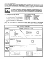
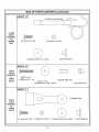
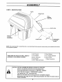
OWNER'S
MANUAL
£nRFT [MRll°
Caution:
Read and follow
all Safety Rules
and Instructions
Before Operating
This Equipment
42 _NCH MOWER
GRASS CATCHER
•
•
,
•
Sears, Roebuck
Assembly
Operation
Customer Responsibilities
Repair Parts
and Co., Hoffman
Estates, IL 60179 U.S.A.
SAFETY
Practices RULES
for Ride-On
Safe Operation
Mowers
IMPORTANT: THIS CUTTING MACHINE IS CAPABLE OF AMPUTATING HANDS AND FEET AND THROWING OBJECTS.
FAILURE TO OBSERVE THE FOLLOWING SAFETY INSTRUCTIONS COULD RESULT IN SERIOUS INJURY OR DEATH,
GENERAL
OPERATION
III.
Read, understand, and follow all instructions in the manual
and on the machine before starting
Only allow responsible adults, who are familiar with the
instructions, to operate the machine
Ctear the area of objects such as rocks, toys, wire, etc, which
could be picked up and thrown by the blade.
Be sure the area +sclear of other people before mowing Stop
machine if anyone enters the area
Never carry passengers
DO not mow in reverse unless absolutely necessary Always
look down and behind before and while backing.
Be aware of the mower discharge direction and do not point
it at anyone Do not operate the mower without either the
entire grass catcher or the guard in place
Slow down before turning
Never leave a running machine unattended
Always turn off
blades, set parking brake, stop engine, and remove keys
before dismounting
Turn off blades when not mowing
Stop engine before removing grass catcher or unclogging
chute
Keep children out of the mowing area and under the watchful
care of another responsible adult
Be alert and turn machine off if children enter the area
Before and when backing, took behind and down for small
children
•
Never carry children. They may fall off and be seriously
injured or interfere with the safe machine operation
Never allow children to operate the machine
Use extra care when approaching blind corners, shrubs,
trees, or other objects that may obscure vision
IV.
SERVICE
•
Use extra care in handling gasoline and other fuels They
are flammable and vapors are explosive
Use only an approved container
Never remove gas cap or add fuel with the engine
running Allow engine to cool before refueling Do not
smoke
Never refuel the machine indoors,
Mow only in daylight or good artificial light
Do not operate the machine while under the influence of
alcohol or drugs
Never store the machine or fuel container inside where
there is an open flame, such as a water heater
Never run a machine inside a closed area
Watch for traffic when operating near or crossing roadways
Use extra care when Ioad!ng or unloading the machine into a
trailer or truck
IL
SLOPE OPERATION
.
Slopes are a major factor related to loss+of-control and tipover
accidents, which can result in severe in ury or death. All slopes
requireextracaution
Ifyoucannotbackuptheslopeor
fyoufeel
uneasy on it, do not mow it
•
DO:
•
Mow up and down slopes, not across
Remove obstacles such as rocks, tree limbs, etc
Watch for holes, ruts, or bumps+ Uneven terrain could
overturn the machine Tafl grass can hide obstacles.
Use slew speed Choose a low gear so that you will not have
to stop or shift while on the slope
Followthe man ufacturer's recommendations for wheel weights
or counterweights to improve stability
Use extra care with grass catchers or other attachments
These can change the stability of the machine
Keep all movement on the slopes slowand gradual Do not
make sudden changes in speed or direction+
Avoid starting or stopping on a slope If tires lose traction,
disengage the blades and proceed slowly straight down the
slope
Keep nuts and bolts, especially blade attachment bolts, tight
and keep equipment in good condition
Never tamper with safety devices
Check their proper
operation regularly
Keep machine free of grass, leaves, or other debris build-up+
Clean oil or fuel spillage
Allow machine to cool before
storing
Stop and inspect the equipment if you strike an object
Repair, if necessary, before restarting,
Never make adjustments or repairs with the engine running
Grass catche+ components are subject to wear, damage,
and deterioration, which could expose moving parts or allow
objects to be thrown. Frequently check components and
replace with manufacturer s recommended parts, when necessary
Mower blades are sharp and can cuL Wrap the blade(s) or
wear gloves, and use extra caution when servicing them
Check brake operation frequently
required
DO NOT:
Do not turn on slopes unless necessary, and then, turn slowly
end gradually downhill, if possible
Do not mow near drop-offs, ditches, or embankments. "['he
mower could suddenly turn over if a wheel is over the edge of
a cliff or ditch, or if an edge caves in.
Do not mow on wet g+:ass Reduced traction could cause
sliding
Do not try to siabilize the machine by putting your foot on the
ground
Do not use grass catcher on steep slopes
CHILDREN
Tragic accidents can occur if the operator is not alert to the
presence of children Children are often attracted to the machine
and the mowing activity Neverassume that children will remain
where you last saw them
I _
Adjust and service as
tant safety precautions.
It means
CAUTION!!! BECOME ALERT!If YOUR
LookforthissymboltopointoutimporSAFETY IS INVOLVED.
CAUTION:
Always disconnect spark
plug wire and place wire where it cannot
contact spark plug in order to prevent
accidental starting when setting up,
transporting,
adjusting
or making
repairs.
2
I
CONGRATULATIONS on you r purchase of a Sears Craftsman Grass Catcher. it has been designed, engineered and
manufactured to give you the best possible dependability
and performance.
Should you experience any problems you cannot easily
remedy, please contact your nearest Sears Service Center/Department We have competent, well trained technicians and the proper tools to service or repair this uniL
Please read and retain this manual. The instructions will
CUSTOMER
RESPONSIBILITIES
= Read and observe the safety ruleSo
o Follow a regular schedule in maintaining, caring for
and using your Grass Catcher.
. Follow the instructions under "Customer Responsibilities" and "Storage" sections of this Owner's Manual
enable you to assemble and maintain your Grass Catcher
properly Always observe the SAFETY RULES,
MODEL
NUMBER 917.249491
SERIAL
NUMBER
DATE OF
PURCHASE
THE MODEL AND SERIAL NUMBERS WILL BE
FOUND ON THE MODEL PLATE ATTACHED TO
THE INSIDE OF THE MOUNTING BRACKET.
YOU SHOULD RECORD BOTH SERIAL NUMBER
AND DATE OF PURCHASE AND KEEPIN A SAFE
PLACE FOR FUTURE REFERENCE,
NOTE: To make debris disposal easier 30 gallon plastic
trash bags may be inserted in plastic grass containers. To
order, see repair parts section of this manual
LIMITED ONE YEAR WARRANTY ON
CRAFTSMAN GRASS CATCHER
For one year from the date of purchase, when this grass catcher attachment is maintained according to the operating
and maintenance instructions in the owner's manual, Sears will repair free of charge any defect in material or
workmanship
This warranty does not cover:
•
Expendable items which become worn during normal use, such as bags or mower blades,
•
Repairs necessary because of operator abuse or negligence, including the failure to maintain the equipment
according to instructions contained in the owner's manual.
•
Grass catcher attachments used for commercial
or rental purposes.
WARRANTY SERVICE iS AVAILABLE BY RETURNING THE CRAFTSMAN GRASS CATCHER TO THE NEAREST
SEARS SERVICE CENTER/DEPARTMENT
IN THE UNITED STATES. THIS WARRANTY APPLIES ONLY WHILE
THIS PRODUCT IS IN USE IN THE UNITED STATES
This warranty gives you specific legal rights, and you may also have other rights which vary from state to state.
SEARS, ROEBUCK AND CO, D/817 WA, HOFFMAN ESTATES, ILLINOIS.
60179
i,i
TABLE OF CONTENTS
SAFETY RULES ...................................................................2
WARRANTY .............................................................................
3
BAG OF PARTS ...................................................................
4-5
ASSEMBLY ..............................................................................
6
OPERATION ...............................................................................
11
CUSTOMER RESPONSIBILITIES ............................... 12
STORAGE ......................................................................
12
REPAIR PARTS ............................................................ 14-16
PARTS ORDERING/SERVICE ................. BACK COVER
Know
Your
Grass
Catcher
READ THIS OWNER'S MANUAL AND SAFETY RULES BEFORE ASSEMBLING OR OPERATING YOUR GRASS
CATCHER. Compare the illustrations with the carton contents to familiarize yourself with the parts before starting the
assembly. Study the operating instructions and safety precautions thoroughly to insure proper functioning of your Grass
Catcher and to prevent injury to yourself and others. Save this manual for future reference.
The operation of any tractor can result in foreign objects thrown into the eyes, which can result in
severe eye damage. Always wear safety glasses or' eye shields before starting your tractor and while
mowing. We recommend wide vision safety mask for over the spectacles or standard safety glasses
UNPACKING
,
INSTRUCTIONS
CARTON
(2)
(2)
(1)
(1)
(1)
Remove all parts and packing materials from carton
Turn carton upsidedown on floor of work are& To
protect grass catcher cover during assembly place
cover upsidedown on overturned carton.
=
CONTENTS:
Container Tops
Container Bottoms
Upper Chute
Lower Chute
Support Post
(1)
(1)
(1)
(1)
(1)
Mounting Bracket
Cover Assembly
Cover Seal
Bag of Parts
Owner's Manual
Check carton contents against list, Be sure allparts are
there.
NOTE:
groups.
For ease of assembly
aside of. your work.area,
!ay out all hardware i.n the. following
_-acn step of the assembly instructions wilJ iaent ry me group neeaea for mat step.
BAG OF PARTS CONTENTS
ASSEMBLY
HARDWARE
LOCATION
SHOWN
"X 4/Bolt5/1618x3/4
(4) Bolt 5/16 _ 18 x 1/2 Self Tapping
GROUP
SUPPORT
POST
TO
MOUNTING
BRACKET
SIZE
©
REAR
MOUNTING
BRACKET
TO
DRAW BAR
SUPPORT
POST
TO
CONTAINER
SUPPORT
ACTUAL
(4) Locknut 5/16-18
"_
"B" i
11111111t111111111111
(3) Bolt 5/16 - 18 x 3/4
(3) Locknut 5/16-18
(1) Bracket Support Pin
(1) Retainer Spring
(3) Tubing End Caps
t
4
BAG OF PARTS CONTENTS
(continued)
_ROUP "D"[
(2) Latch
ly
[
LOWER
CHUTE
ASSEMBLY
TO
MOWER
DECK
©
(2) Screw #10 x 5/8
(2) Washer, Lock #10
(2) Nut, Weld #10
(2) Washer 3/16 x 3/4 x 16 Ga.
GROUP"E"[
CHUTE
LATCH
ASSEMBLY
to
UPPER
CHUTE
-4q%1o o
(I)Screw #I0'× 1-118
(t) Spacer, Split #10
(2) Washer 3/16 x 3/4 x 16 Ga.
GROUP
(1) Nut, Acorn #10
"F "1
(1) Rubber Latch
CHUTE
LATCH
ASSEMBLY
to
LOWER
CHUTE
©
(1) Screw #10 x 5/6
(1) Washer, Lock #10
5
(1) Washer 3/16 x 3/4 x 16 Ga.
(1) Nut, Weld #10
ASSEMBLY
PARTS
IDENTIFICATION
COVER
UPPER CHUTE
FULL
BAGGER
INDICATOR
CHUTELATCH
%,
GRASS
CATCHER
CONTAINERS
\
LOWER
CHUTE
_
"_'_
LOWER
CHU'_
E
ATTACHING
STRAPS
NOTE: When right hand (R H.) and left hand (L.H.) are mentioned in this man ua, t means when you are seated on the tractor,
in the operator's position_
THESE ARE THE TOOLS YOU WILL NEED TO
ASSEMBLE YOUR GRASS CATCHER:
(1) 3/8" Wrench
(1) Drive Ratchet
(1) 1/2" Wrench
(1) 3" or longer Extension
(2) 9/16" Wrenches
(1) 1/2" Socket
(1) Short Handle
Phillips Screwdriver'
(1) 9/16" Deep well Socket
CAUTION:
BEFORE ASSEMBLING GRASS CATCHER TO TRACTOR:
•
Depress clutch/brake pedal fully and set parking brake.
•
Place gearshift/motion
°
Place attachment clutch in "DISENGAGED"
•
Turn ignition key "OFF" and remove key.
•
•
Make sure the blade and all moving parts have completely stopped,
Disconnect spark plug wire from spark plug and place wire where it cannot come in
contact with plug,
control lever in "NEUTRAL"
6
position.
position,
BLY
1
REAR MOUNTING
BRACKET
(See Figs. 1 & 2)
Use Hardware - - GROUP
COVER
SEAL (See Fig. 3)
No hardware
required
"A"
Align mark on seal with mark at cover opening
Work seal into opening so cover sits between flanges
of seal
Only one set of hardware in GROUP "B" will be used to
mount the rear mounting bracket. To determine which set
is correct for your tractor, check to see if there are (2) two
upper corner ribs on each side of drawbar, tf your tractor
has the upper corner ribs, use the (4) four self tapping bolts
If your tractor does not have the corner ribs, use the set of
(4) four bolts and Iocknuts
ALIGNMENT
MARKS
SELF TAPPING BOLTS
•
Assemble the mounting bracket, lanced tabs towards
bottom, using the four formed holes on the drawbar
NOTE: Start the self tapping bolts into holes on the
drawbar at least two full turns and remove. This will make it
much it much easier to fasten the bolts once the mounting
bracket is in place
=
COVER SEAL
Fig. 3
Install the four bolts as shown and tighten securely
UPPER CORNER
RIBS
UPPER CORNER
RIBS
SUPPORT POST (See Fig. 4)
Use Hardware - - GROUP "B"
loaded and locked to the cover. Handle
cover assembly carefully so as not to
unlatch
cover from
the container
CAUTION:theContainer
support
is spring
support.
I_
SELF
TAPPING
BOLTS
•
Rotate cover assembly onto its side as shown.
•
Assemble support post to container support with the
three (3) hex bolts and Iocknuts. Tighten securely_
Fig. 1
BOLTS AND LOCKNI, JTS
=
Assemble the mounting bracket, lanced tabs towards
bottom, using the four smaller inside holes on the
drawbar,
•
Install the four bolts and Iocknuts as shown and tighten
securely
HEX BOLTS
BOLTS
SUPPORT
POST
LOCKNUTS
/•
/
•
/
/
LOCKNUTS
Fig. 4
LANCED TABS TOWARD
Fig. 2
BOTTOM
7
I
ASSEMBLY
MOUNTING
(See Fig. 5)
Use HardwareTO - TRACTOR
- GROUP "C"
CONTAINER
No hardware
NOTE: For ease of assembly, you may wish to obtain the
assistance of another person for mounting assembly to
tractor
(See Fig. 6)
•
Place bottom half inside of top half, as shown
o
Place one foot inside bottom half and lift top half to meet
bottom half
=
Press halves tightly together while lifting top to lock into
place as shown
Raise seat on tractor to allow assembly to be mounted.
With cover closed, lift assembly and place support post
inside mounting bracket. Allow assembly to rest on
lanced tabs of mounting bracket.
ASSEMBLY
required
IMPORTANT:
BEFORE LOCKING THE TABS, HOOKED
EDGES ON BOTH HALVES MUST OVERLAP TO FORM
SEAL AS SHOWN IN INSET
Line up holes in mounting bracket with holes in support
post and insert bracket support pin Secure with retainer spring
°
Repeat for second container.
Unlatch and open cover.
Install the three (3) tubing end caps onto container
support
Tap each end cap onto container support tubes to seat
securely
COVER ASSEMBLY
CONTAINER
BOTTOM
HALF
RETAINER
SPRING
PRESSTOGETHER
TO FORM SEAL
WHILE LIFTING
TOP HALF
TAB
ASSEMBLY CHECK: Squeeze sides of lower half of corrtainer and check that there is no gap between upper and
lower halve& If a gap appears, unlock tabs to separate
container halves and repeat instructions above.
f_
i
,_-
_
_
f,
END CAP
SUPPOR"
LANCED TABS
Fig. 6
MOUNTING
BRACKET
Fig. 5
8
ASSEMBLY
6
CONTAINER
7
MOUNTING
(See Fig. 7)
LOWER CHUTE
Use Hardware--
(See Fig. 8 & 9)
GROUP "D"
•
Install two latch hook assemblies, to lower chute using
screw, washer, lock washer, and weld nut as shown
Install one container to left side first with warning to
outside of unit. Install other container to right side.
°
Tighten hardware securely_
•
Raise and hold deflector shield in upright position
NOTE: Right container should always overlap left container at center support.
°
•
=
Place front of chute over front of mower deck opening
and slide into place, as shown
Hook front latch into tab hole on front of mower deck
•
Hook rear latch into tab hole on back of mower deck.
•
If your tractor is equipped with gage wheels on the
deck, then it will be necessary to use the hole in the
R.H. gage wheel mounting bracket•
No hardware
•
required
Close cover and lock latch handle over center support
tube.
COVERLATCH
HANDLE
from mower. Raise and hold guard when
attaching lower chute and allow it to rest
CAUTION: Do not remove discharge guard I
on chute while in operation.
CONTAINER
LOCK WASHER
CONTAINER
HANDLE
SCREW
_
CENTER
SUPPORT
CONTAINER
3
Fig. 7
Fig. 8
WITH OUT
GAGE
WHEELS
fJ"_
......
•_
DEFLECTOR
©
WITH
GAGE
WHEELS
Fig. 9a
DEFLECTOR
"
9
"
SHIELD
ASSEMBLY
CHUTE
LATCH
ASSEMBLY
UPPER
CHUTErequired
(See Fig. 11 &12)
No hardware
(See Fig. 10)
Use Hardware
o
e
- - GROUP
"E & F"
Assemble latch pin to upper chute, as shown.
Assemble rubber latch to lower chute, as shown..
Tighten all hardware securely.
Lower mower deck to its lowest cutting position
,
Assemble upper chute by inserting curved end into
hole in back of cover,
NOTE: Handle carefully so as not to damage full bagger
indicator_
WASHERS
3/16 x 3/4 x 16 Ca.
#10 x 1-1/8" SCREW
•
SPLIT
SPACER
UPPER CHUTE
•
Push in and turn upper chute until it is in line with lower
chute.
a
Align the bosses on lower chute with alignment slots on
upper chute and slide together.
o
Secure with rubber latch by hooking hole in latch over
latch pin.
FULL BAGGER
I/ACORN
UPPER
NUT
INDICATOR
HANDLE
#10 x 5/8"
RUBBER
LATCH
SCREW
LOWERCHUTE.-----------
WELD
WASHER
3/16x3/4x16
/
Ca.
LOCK WASHER
o_J
Fig. 10
Fig. 11
ALIGNMENT
SLOT
LATCH PIN
Fig. 12
LEVEL MOWER
DECK
No hardware
required
.
10
Be sure deck is properly leveled for best mower performance See your tractors owner's manual for instructions
OPERATION
TIPS FOR IMPROVED
OPERATION:
Follow the mower operation
owner's manual
BAGGING
instructions
@
in your tractor
Avoid cutting wet grass or in the morning while the dew
is still heavy. Grass clippings collected under these
conditions tend to be sticky and adhere to the walls of
the flow path causing clogging.
Your bagger is equipped with a full bagger indicator. As
the bags become full, movement of the wheel will slow
down and/or stop, indicatingthat the bags are full or the
chutes have become clogged. Care should be taken
not to damage the parts and that the wheel spins freely
at the beginning of each use
When operating your grass catcher on a lawn where grass
and leaf bagging equipment has not been used, you are
picking up thatch and debris that has accumulated for long
periods of time. The amount collected and the total time of
operation may be greater than you will experience with
regular use of your grass catcher_
If the grass catcher fails to pick up cut grass or leaves,
it is an indication that clogging has occurred in the
_YsStemor that the grass catcher containers are full.
ually this is indicated by the stopped movement of
the full bagger indicator.
Always run throttle at full speed when bagging°
a.
Select a gear low enough to give good mower cutting
performance, good quality cut and good bagging performance
NOTE: It may be necessary to overlap width of cut to suit
your conditions
•
If grass is extremely tall, it should be mowed twice. The
first time relatively high, the second time to desired
height
°
Use left hand side of mower for trimming.
°
Plastic trash bags can be inserted inside grass catcher
containers for ease of debris disposal. To remove the
plastic trash bags when full:
a. Raise seat. Unlatch and raise cover.
b.
- Slide out containers and dispose of clippings.
- Replace containers, close cover, and latch.
b,
With the container resting on the ground, close and
secure the top of the plastic lawn bag.
d.
Tip the container on its side and slide the filled bag
from the container.
e.
Install a new plastic lawn bag with the edges of the
bag draped over upper lip of the Container (for
replacement
bags refer to REPLACEMENT
PARTS)_
f.
Repeat for other container.
g.
Reinstall containers making sure right container
overlaps left container at center support.
h.
Close cover and secure latch over center support
tube.
Unlatch chutes and check for clogging
Remove all debris in chutes.
Reassemble and latch chutes
C.
Check to insure full bagger indicator has not become clogged.
- The air passage hole must be clear of debris
Gently insert a small twig or wire into passageway to clear_
Remove one container at a time by grasping container handles and pulling toward the rear, off of the
tube rails_
c.
Disengage blades, shift into neutral, engage the
parking brake and stop the engine.
- Raise seal Unlatch and raise cover.
CAUTION
11
•
Do not operate mower with grass catcher
partially installed.
•
Disengage blades and stop engine before
leaving tractor seat to empty containers,
unclogging chutes, etc.
o
Close cover before starting.
o
Disengage mower when crossing driveways or gravel surfaces and other areas
where thrown objects could be a hazard.
°
Do not attempt to vacuum up cans or other
potentially hazardous projectiles,
CUSTOME
GENERAL
RESPONSiBiLiTiES
RECOMMENDATIONS
STORAGE
Always observe safety rules when performing any maintenance,
°
Before each use check for loose fasteners.
•
Clean unit thoroughly after each use.
BLADE
When grass catcher is to be stored for a period of time,
clean it thoroughly, remove all dirt, grass, leaves, etc. Store
in a clean, dry place,
CARE
For best results mower blades must be kept sharp, Replace bent or damaged blades
o See BLADE CARE instructions in your tractor owner's
manual.
I&
TO REMOVE
Depress clutch brake pedal fully and set
parking brake.
o
Place gearshift/motion
"NEUTRAL" position.
Place clutch control
position.
°
Turn ignition
control
lever
in
in "DISENGAGED"
key to "OFF" position,
•
Make sure blades and all moving
have completely stopped.
o
Disconnect spark plug wire(s) from spark
plug(s) and place wire where it cannot come
in contact with plug.
GRASS
CATCHER
Reverse appropriate steps in ASSEMBLY
manual
CAUTION:
BEFORE PERFORMING ANY
MAINTENANCE
, SERVICE OR ADJUSTMENTS:
•
containers,
Empty containers after each
use and before storing.
Failure to do so
may result in spontaneous
combustion
CAUTION:
Do not leave grass in bagger
which could develop into a fire.
parts
CAUTION:to Grass
subject
wear, catcher
damage components
and deterioraare
tion, which could expose moving parts or
allow objects to be thrown.
Frequently
check components
and replace with
manufacturer's recommended parts, when
necessary.
12
section of this
13
REPAIR PARTS
GRASS
CATCHER-
- MODEL NUMBER
917.249491
2
/
3
6
7
1
4
8 9
\
2O
10
\
2O
2
2
4_
35
26
31
27
/
31
27
/
31
26
25
REPAIR PARTS
GRASS CATCHER-
.,,&
KEY
NO.
PART
NO,
1
2
3
4
5
6
7
8
"9
f0
11
42
13
4
15
7192J
69180
127533
126817
126840
18021008
130933
87175
19061216
7206J
60867
10071000
109808X
2029J
130760
16 i3_
1"8" 12683_
_'T6T010
21
132796
22
133235
- MODEL NUMBER
DESCRIPTION
KEY
NO.
Tie, Cable
Nut, Crownlock #10-24
Screen, Cover
Cover
Chute, Upper
Screw, Special #10-!4 x 1/2
Full Bagger Indicator
Screw, #10-24 x 1-1/8
Washer 3/16 x 3/4 x 16 Ga,
23 132983
24 126813X
25 63124
26 4939M
27 74760512
28 130889
29 17490508
30 131137
31 134496
32 -126919X
33 128600
34 127534
35 129584
36 129586
37 132256
38 130895
39 135495
40 71141008
-104419X
-137865
Spacer, Split
Nut, Acorn #10-24
Washer, lock
Latch, Chute
Nut, Weld
Latch, Hook
Rubber, Latch
Chute, Lower
Screw #10-24 x 5/8
Spring, Cover L.H. (black)
Spacer. Cover
PART
NO.
917.249491
DESCRIPTION
Spring, Cover Roll. (gray)
Post, Support
Locknut 5/16 x 18
Spring, Retainer
Bolt, Hex 5/16-18 x 3/4
Bracket, Mounting
Screw 5/16-18 x 1/2 Hex, Self Tapping
Pin, Support Post
Plug, Tubing End
Bagger, Frame
Pin, Hinge
Gasket, Cover
Container, Top
Container, Bottom
Seal, Cover
Latch Handle, Cover
Strip, Seal
Screw #10-24 x 1/2
Bag, 3.0 miL 30 Gallon Trash (not included with bagger)
Owner's Manual
®
S _AI S
OWNER'S
MANUAL
MODEL NO.
917.249491
42 iNCH MOWER
GRASS CATCHER
Each grass catcher has its own model number.
The Model Number for your grass catche' will be found on the model
plate attached to the inside of the mountin, _rackeL
All parts listed herein may be ordered from any Sears, Roebuck and Co.
Service Center and most Retail Stores.
WHEN ORDERING REPAIR PARTS, ALWAYS
ING INFORMATION:
= PRODUCT-
GIVE THE FOLLOW-
GRASS CATCHER
• MODEL NUMBER - 917.249491
HOW TO ORDER
REPAIR PARTS
• PART NUMBER
• PART DESCRIPTION
Your Sears merchandise has added value when you consider Sears has
service units nationwide staffed with Sears trained technician&_, professional technicians specifically trained to insure that we meet our pledge
to you, we service what we sell.
Sears, Roebuck
137865
10.&92
and Co., Hoffman
Estates, IL 60179 U.S.A.
PRINTED IN U.S_A,.