1
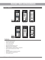
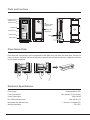
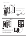
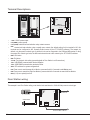
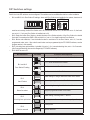
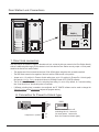
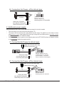
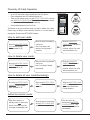
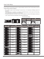
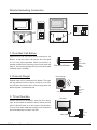
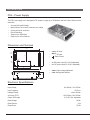
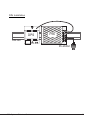
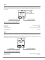
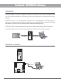
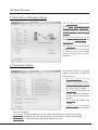
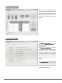
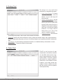
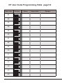
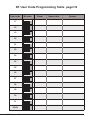
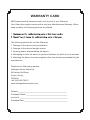
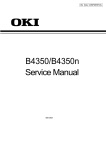
DT 2-wire Video Intercom System Technical Guide CONTENT Section1 - Introduction System Features- - - - - - - - - - - - - - - - - - - - - - - - - - - - - - - - - - - - - - - - - - - - - - - - - - - - - - - - System Capacity- - - - - - - - - - - - - - - - - - - - - - - - - - - - - - - - - - - - - - - - - - - - - - - - - - - - - - - - System Extension- - - - - - - - - - - - - - - - - - - - - - - - - - - - - - - - - - - - - - - - - - - - - - - - - - - - - - - System Function- - - - - - - - - - - - - - - - - - - - - - - - - - - - - - - - - - - - - - - - - - - - - - - - - - - - - - - - - Section2 - Units and Installations 1 1 1 1 1 4 Door Station- - - - - - - - - - - - - - - - - - - - - - - - - - - - - - - - - - - 4 Features- - - - - - - - - - - - - - - - - - - - - - - - - - - - - - - - - - - - - - - - - - - - - - - - - - - - - - - - - - - - - - - 4 Parts and functions - - - - - - - - - - - - - - - - - - - - - - - - - - - - - - - - - - - - - - - - - - - - - - - - - - - - - - - 5 Place Name Plate- - - - - - - - - - - - - - - - - - - - - - - - - - - - - - - - - - - - - - - - - - - - - - - - - - - - - - - - 5 Electronic Specifications- - - - - - - - - - - - - - - - - - - - - - - - - - - - - - - - - - - - - - - - - - - - - - - - - - - - 5 Standard Installation - - - - - - - - - - - - - - - - - - - - - - - - - - - - - - - - - - - - - - - - - - - - - - - - - - - - - - 6 Installation with expanding panel- - - - - - - - - - - - - - - - - - - - - - - - - - - - - - - - - - - - - - - - - - - - - - 6 Terminal Descriptions- - - - - - - - - - - - - - - - - - - - - - - - - - - - - - - - - - - - - - - - - - - - - - - - - - - - - - 7 Door Station wiring - - - - - - - - - - - - - - - - - - - - - - - - - - - - - - - - - - - - - - - - - - - - - - - - - - - - - - - 7 DIP Switches settings - - - - - - - - - - - - - - - - - - - - - - - - - - - - - - - - - - - - - - - - - - - - - - - - - - - - - 8 Door Station Lock Connections- - - - - - - - - - - - - - - - - - - - - - - - - - - - - - - - - - - - - - - - - - - - - - - 9 Proximity ID Card Operation - - - - - - - - - - - - - - - - - - - - - - - - - - - - - - - - - - - - - - - - - - - - - - - - 11 Monitor - - - - - - - - - - - - - - - - - - - - - - - - - - - - - - - - - - - - - 13 Features- - - - - - - - - - - - - - - - - - - - - - - - - - - - - - - - - - - - - - - - - - - - - - - - - - - - - - - - - - - - - - - 13 Electronic Specifications- - - - - - - - - - - - - - - - - - - - - - - - - - - - - - - - - - - - - - - - - - - - - - - - - - - 13 Terminal Descriptions- - - - - - - - - - - - - - - - - - - - - - - - - - - - - - - - - - - - - - - - - - - - - - - - - - - - - - 14 Intercom function- - - - - - - - - - - - - - - - - - - - - - - - - - - - - - - - - - - - - - - - - - - - - - - - - - - - - - - - - 14 Camera Auto Switching - - - - - - - - - - - - - - - - - - - - - - - - - - - - - - - - - - - - - - - - - - - - - - - - - - - - 16 Color Picture Memory - - - - - - - - - - - - - - - - - - - - - - - - - - - - - - - - - - - - - - - - - - - - - - - - - - - - - 16 SD Card- - - - - - - - - - - - - - - - - - - - - - - - - - - - - - - - - - - - - - - - - - - - - - - - - - - - - - - - - - - - - - - 16 User Code Setup- - - - - - - - - - - - - - - - - - - - - - - - - - - - - - - - - - - - - - - - - - - - - - - - - - - - - - - - - 17 Monitor Extending Connection - - - - - - - - - - - - - - - - - - - - - - - - - - - - - - - - - - - - - - - - - - - - - - - 18 Accessories- - - - - - - - - - - - - - - - - - - - - - - - - - - - - - - - - - 19 PS5 - Power Supply- - - - - - - - - - - - - - - - - - - - - - - - - - - - - - - - - - - - - - - - - - - - - - - - - - - - - - - 19 DPS- - - - - - - - - - - - - - - - - - - - - - - - - - - - - - - - - - - - - - - - - - - - - - - - - - - - - - - - - - - - - - - - - - 21 DBC- - - - - - - - - - - - - - - - - - - - - - - - - - - - - - - - - - - - - - - - - - - - - - - - - - - - - - - - - - - - - - - - - - 21 DBC-4 Unit- - - - - - - - - - - - - - - - - - - - - - - - - - - - - - - - - - - - - - - - - - - - - - - - - - - - - - - - - - - - - 23 DPS-4 Unit- - - - - - - - - - - - - - - - - - - - - - - - - - - - - - - - - - - - - - - - - - - - - - - - - - - - - - - - - - - - - 23 DCU Unit - - - - - - - - - - - - - - - - - - - - - - - - - - - - - - - - - - - - - - - - - - - - - - - - - - - - - - - - - - - - - - 25 Section3 - Cables and Connections 28 General Rules for Installation- - - - - - - - - - - - - - - - - - - - - - 28 Connecting the Connectors - - - - - - - - - - - - - - - - - - - - - - - - - - - - - - - - - - - - - - - - - - - - - - - - - 28 Installation Height - - - - - - - - - - - - - - - - - - - - - - - - - - - - - - - - - - - - - - - - - - - - - - - - - - - - - - - - 28 Door Station Install Condition- - - - - - - - - - - - - - - - - - - - - - - - - - - - - - - - - - - - - - - - - - - - - - - - 28 Table of Cables and Distance- - - - - - - - - - - - - - - - - - - - - - - - - - - - - - - - - - - - - - - - - - - - - - - - 29 System Wirings and Connections- - - - - - - - - - - - - - - - - - - 30 1. Basic IN-OUT wiring mode- - - - - - - - - - - - - - - - - - - - - - - - - - - - - - - - - - - - - - - - - - - - - - - - 30 2. Basic IN-OUT wiring mode (1~n risers) - - - - - - - - - - - - - - - - - - - - - - - - - - - - - - - - - - - - - - - 31 3. IN-OUT wiring with One-user distributor- - - - - - - - - - - - - - - - - - - - - - - - - - - - - - - - - - - - - - - 32 4. Basic Star wiring mode- - - - - - - - - - - - - - - - - - - - - - - - - - - - - - - - - - - - - - - - - - - - - - - - - - - 33 5. 4 Door Stations and star wiring mode - - - - - - - - - - - - - - - - - - - - - - - - - - - - - - - - - - - - - - - - 34 6. 1 Door Station and 2 CCTV cameras- - - - - - - - - - - - - - - - - - - - - - - - - - - - - - - - - - - - - - - - - 35 7. Mixed 1/4 user distributors wiring - - - - - - - - - - - - - - - - - - - - - - - - - - - - - - - - - - - - - - - - - - - 36 Section4 - Setup and Debug 37 System Operations- - - - - - - - - - - - - - - - - - - - - - - - - - - - - 37 Busy State Management - - - - - - - - - - - - - - - - - - - - - - - - - - - - - - - - - - - - - - - - - - - - - - - - - - - 37 Door Station Function - - - - - - - - - - - - - - - - - - - - - - - - - - - - - - - - - - - - - - - - - - - - - - - - - - - - - 38 System Setup- - - - - - - - - - - - - - - - - - - - - - - - - - - - - - - - - 39 What’s User Code- - - - - - - - - - - - - - - - - - - - - - - - - - - - - - - - - - - - - - - - - - - - - - - - - - - - - - - - 39 What's Slave Address - - - - - - - - - - - - - - - - - - - - - - - - - - - - - - - - - - - - - - - - - - - - - - - - - - - - - 40 Online search- - - - - - - - - - - - - - - - - - - - - - - - - - - - - - - - - - - - - - - - - - - - - - - - - - - - - - - - - - - 41 Simulating Call - - - - - - - - - - - - - - - - - - - - - - - - - - - - - - - - - - - - - - - - - - - - - - - - - - - - - - - - - - 42 Section5 - DT CONFIG Software 43 Introduction- - - - - - - - - - - - - - - - - - - - - - - - - - - - - - - - - - - - - - - - - - - - - - - - - - - - - - - - - - - - - 43 Hardware connection- - - - - - - - - - - - - - - - - - - - - - - - - - - - - - - - - - - - - - - - - - - - - - - - - - - - - - 43 Interface Preview- - - - - - - - - - - - - - - - - - - - - - - - - - - - - - - - - - - - - - - - - - - - - - - - - - - - - - - - - 44 Section1 - Introduction System Features • With only 2 wires (no polarity) throughout the whole installation, the 2-wire DT system is a simplified installation system with minimum wiring and powerful features. The minimum wiring drastically reduces installation times and errors. By means of FM video modulation and ASK data transmission technology, system provides better protection against interference, which guarantees best color quality at all points of the installation. • Centralized power supply for the entire system. With advanced power management, the whole system use only one power supply, so there is no power supply needed for any Monitor or other system parts. • Use Plug-in connectors and DIP switchers for more rapid installation. • Flexible cable connection to wire, support in-out, branching and mixed mode. • Multi Monitors for one apartment/house in same User Code, and automatically swithing the video. • Online searching and diagnose function for installer. • Using PC to program and diagnose the system. System Capacity • • • • Max. 4 Door Stations, or 3 Door Station plus 2 CCTV cameras, or 1 Door Station plus 6 CCTV cameras. Max. 32 Monitors in a system, max.4 Monitors in same User Code. Proximity access control function, max. 1000 user ID cards. Maximum 150 meters distance from Door Station to the farest Monitor. System Extension • • • • Connect Door Strike and Exit Button to Door Station directly. Connect door bell and extra ringer to Monitor directly. Control staircase light or relay executors for second electronic lock. Connect up to 6 CCTV cameras by DCU unit. System Function • • • • 1 Name list intercom Inner call intercom among Monitors in same Room Code One Monitor can be programmed as Guard unit Color Memo or SD card DVR function Villa Application CALL Although the DT system is mainly designed for the small apartment system usage, it can be used in villa or villa group applications. Multi Monitors can be installed in a family with the same User Code, or many houses can be connected as one system, and all of these Monitors can have calling conversation each other. CALL CALL UNLOCK UNLOCK UNLOCK TALK/MON TALK/MON TALK/MON IN-USE IN-USE IN-USE CALL CALL UNLOCK UNLOCK TALK/MON TALK/MON IN-USE IN-USE 2 CALL UNLOCK TALK/MON IN-USE 2 CALL UNLOCK TALK/MON IN-USE 2 Apartment Applications CALL UNLOCK TALK/MON IN-USE This is the most common way that the system is used. One building or multi buildings can be connected as one system. Every apartment can open the door, and the users in the system can have intercom talk each other. 2 CALL UNLOCK TALK/MON IN-USE 2 AC DPS PS5 2 DT - System - Technical Guide 2 3 Section2 - Units and Installations Door Station Bit-4=off 123456 ON DMR11/ID/D8 DMR11/D8 EP11/D24 Bit-4=on 123456 ON Features • • • • • • • • • • • • DMR11/ID/S4 DMR11/S4 EP11/S12 Full anodize aluminum panel. SONY color CCD camera. camera angle adjustable. ID card access control Night-view LED with CDS light sensor. Backlit name plate for each button. Use DIP switches for multi Door Station configuration. Direct connect to electronic lock of 12Vdc. Exit button. USB-RS485 interface to connect to computer. Plug-in connector to connect bus line. On line Monitor search. DT - System - Technical Guide 4 Parts and functions Camera Lens CDS Sensor Infrared LED 308 mm Microphone Name plate 298.5 mm Camera Angle adjustment Speaker Speaker Vol adjustment Connection Board Call button 18 mm 123 mm 45 mm 114.5 mm Place Name Plate Press down and shift right/left to open the transparent name plate cover, then insert the name paper, then put the plate cover back to the panel. Note thar double button line panel can be opened both direction, single button line Can only be opened at right side. Da vid Calo Electronic Specifications Power supply: Power Consumption: Unlock Power output: NO, COM exchange contact: Monostable relay activation time: 24Vdc(supplied by PS5) 1W in standby, 15 W in working 12Vdc 300mA Max. 48V dc 1.5A 1 second to 10 minutes ±5% Working temperature:-5ºC +45ºC 5 Standard Installation 114.5 mm Camera Angle adjustment 298.5 mm Open the mounting box of the panel, use a cross screw to adjust the view angle of the camera before installation. 45 mm Installation with expanding panel Jointer*2 ON L1 JP-LK DT - System - Technical Guide L2 1 2 3 SET CN-LK The double button line expantion panel can only be connected to double button line Door Station; the single button line expantion panel can only be connected to single button line Door Station. For example, the EP11/Dx can only be connected to DMR11/Dx Door Station. T/R T/R+ +12V LK - (GND) LK+(COM) N.O. EB+ EB - 123456 Note RS-485 Stopper PA PB BUS 6 T/R T/R+ L1 L2 RS-485 L1 1 2 3 L2 PA PB SET 123456 ON CN-LK 1 2 3 JP-LK T/R T/R+ +12V LK - (GND) LK+(COM) N.O. EB+ EB - SET DMR11 Connection Board 123456 ON CN-LK +12V LK - (GND) LK+(COM) N.O. EB+ EB - RS-485 Terminal Descriptions BUS PA PB BUS • • • • • • • • • • • • • +12V: 12VDC power output. LK-(GND): power ground. LK+(COM): electronical load activation relay contact common. NO.: electronical load activation relay normally open contact (the default setting for this terminal is NO, this terminal can be configured to NC, normally-closed contact by the DT CONFIG software). That means, by default, only the power-to-unlock type of electronic lock can be connected to the COM and NO terminal, if using the power-off-to-unlock type locks, the NO terminal must be set to NC contact by the DT CONFIG software. EB+: Exit button. EB-: Exit buton. JP-LK: For electronic lock safety type setting(refer to Door Station Lock Connections). T/R-: USB-RS485 communication terminal negative. T/R+: USB-RS485 communication terminal positive. SET: DIP switches for system configurations. PA: Press once to sent the name list to Monitor; press and hold for 3 seconds to add Master card. PB: Press once to search the Right line Monitor; press and hold for 3 seconds to search left line Monitor. Bus(L1,L2): non-polarity bus line. Door Station wiring +12V LK - (GND) LK+(COM) N.O. EB+ EB - T/R T/R+ 123456 ON + Connect PC SET - RS-485 This example is one Door Station wiring, note that the lock used here is a 12Vdc 300mA power-to-unlock type. Outlet Button L1 PA L2 BUS JP-LK 1 2 3 PB Connect to DPS or DPS-4 7 DIP Switches settings Total 6 bits in the DIP switches can be configured. The switches can be modified either before or after installation. • Bit-1 and Bit 2 is for Door Station ID settings, when mutil Door Stations are installed in the system, these two bit ON(1) OFF(0) ON 1 2 3 4 5 6 • • • • = = ON ON must be set correctly, the first Door Station set to 00, the second one set to 01, the third one set to 10, the fourth one set to 11. If only one Door Station is installed, set to 00. Bit-3: Single line button Door Station or double line button Door Station selection. If the Door Station is a double line button, for examlpe, the DMR11-D8, set this bit to 0, set to 1 for single line button Door Stations. Bit-4: Button code selection; if use the default codes for each button of the Door Station, set to 0, if use the programmed codes, set to 1.(the code for each button can be programmed by the DT CONFIG software, see the program section in this manual) Bit-5: Unlocking time quick selection, by default it is set to 0, for 1 second unlocking time; set to 1 for 5 seconds. (this 5 second unlocking time can be changed by DT-CONFIG software) Bit-6: MUST be set to off. Bit definition Bit state 1 2 3 4 5 6 Function Descriptions Default setting, ID = 0, set to the first Door Station. ON Bit-1 and bit-2 Door Station ID setting 1 2 3 4 5 6 ID = 1, set to the second Door Station. ON 1 2 3 4 5 6 ID = 2, set to the third Door Station. ON 1 2 3 4 5 6 ID = 3, set to the fourth Door Station. ON Bit-3 User ID select 1 2 3 4 5 6 Default setting for using a double line button Door Station. ON 1 2 3 4 5 6 when using a single line button Door Station. ON Bit-4 Button line select 1 2 3 4 5 6 Default setting for using the default codes of the button. ON 1 2 3 4 5 6 using the progremmed codes of the button. ON Bit-5 Unlocking time quick select 1 2 3 4 5 6 Default setting, unlocking time = 1 second. ON 1 2 3 4 5 6 Unlocking time = 5 seconds.(can be changed by software) ON Bit-6 Function reserved 1 2 3 4 5 6 Working state. ON 1 2 3 4 5 6 Function reserved. ON DT - System - Technical Guide 8 T/R T/R+ L2 RS-485 1 2 3 L1 L2 PA PB SET 123456 ON CN-LK L1 1 2 3 JP-LK T/R T/R+ +12V LK - (GND) LK+(COM) N.O. EB+ EB - SET DMR11 Connection Board 123456 ON CN-LK +12V LK - (GND) LK+(COM) N.O. EB+ EB - RS-485 Door Station Lock Connections BUS PA PB BUS 1. Direct lock connection Use the power of the system to supply for the electronic lock, so that the lock can connect to the Door Station directly, without a additional power supply for the electronic lock. Note that the Door Station can only output a 12Vdc power, therefore the kind of lock used is limited. • The rated power of the lock must be less than 12Vdc 300mA when using direct lock connection method. • The GND must connect to the negative of the lock, and the COM connect to the positive . • Jumper set to 1-2 position for Power-to-Unlock safety type; set to 2-3 position for Power-off-to -Unlock type(in this case the Unlock Relay mode should be set to Normally Closed on DT CONFIG software) • The 5th bit of the DIP switches is for the unlocking time setting, it's set to off by default, for 1 second unloking time. If set this bit to on, the unlocking time is 5 seconds. • If different unlocking time is needed to be configured, the DT CONFIG software can be used to change the Unlock Timing on the Parameter tab(see the program section). A. Connection for Power-to-Unlock type: +12V LK - (GND) LK+(COM) N.O. EB+ EB - + 12V 300mA 9 1 2 3 JP_LK Jumper set to 1-2 position DIPS 123456 ON DIPS-5: default set to off, unlocking time is 1 second. (In most cases, 1 second is work for Power-to-Unlock type) B. Connection for Power--off-to-Unlock type: +12V LK - (GND) LK+(COM) N.O. EB+ EB - + 12V 300mA 123456 ON DIPS-5: set to on, unlocking time is 5 seconds. JP_LK 1 Jumper set to 2-3 position 2 3 set to Normally Closed on the Unlock Relay mode on DT software. DIPS 2. Additional power supply When the electronic lock is over 12 Vdc, additional power supply for the lock is needed. • The power supply for the lock must be less than 48Vdc 1.5A. • The Jumper must be removed when using additional power supply. The default is set for Power-to-Unlock type(Normally open), if use Power-off-to-Unlock type, change the Unlock Relay mode to Normally closed on the Parameter tab of DT CONFIG software. • If different unlocking time is needed to be configured, please use the DT CONFIG software to change the setting on the Parameter tab(see the program section). C. Connection for Power-to-Unlock type: Note: Cut off this line when using - + additional power supply +12V LK - (GND) LK+(COM) N.O. EB+ EB - + - 1 2 3 JP_LK Remove the Jumper set to Normally Open on the Unlock Relay mode.(default) DIPS 123456 ON DIPS-5: default set to off, unlocking time is 1 second. (In most cases, 1 second is work for Power-to-Unlock type) D. Connection for Power--off-to-Unlock type: Note: Cut off this line when using + + - - additional power supply +12V LK - (GND) LK+(COM) N.O. EB+ EB - DT - System - Technical Guide JP_LK 1 Remove the Jumper 2 3 set to Normally Closed on the Unlock Relay mode on DT software. DIPS 123456 ON DIPS-5: set to on, unlocking time is 5 seconds. 10 Proximity ID Card Operation • Up to 1000 user cards can be registered by the Door Station. • Easy management with LED state and Sound hint. • There are two master cards, one MASTER CARD ADD card and one MASTER CARD DELETE card,When adding a new master card, the old one will be replaced automatically. • Card reading distance is from 3 to 5 cm. The Master cards are necessary when you add or delete user cards, Please keep the Master cards carefully. However, it is much easier to manage the ID cards using DT-CONFIG software. DMR11/ID/D8 How to add user cards: Show the MASTER CARD ADD card in standby. Note. sounded Di~,Di Show the cards to be added, one by one. Note. Long beep if add success, two long beep if repeated. Show the MASTER CARD ADD card again to exit. However, will exit if no card was showed within 15s. Show the cards to be deleted, one by one. Note. Long beep if deleted successfully Show the MASTER CARD DELETE card again to exit. However, will exit if no card was showed within 15s. How to delete user cards: Show the MASTER CARD DELETE card in standby. Note. sounded Di~,Di How to delete all user cards(formating): Show the MASTER CARD DELETE card in standby. Note. sounded Di~,Di Show theMASTER CARD ADD card to run format operation. Show the MASTER CARD ADD card again within 3 seconds to confirm the Format operation. Authorize master cards: When Door Station is in standby, press PA button and hold for 3 seconds to get into the master card manage state 11 Show the card to be autorized as MASTER CARD ADD , you will hear a long beep*1 show the card to be authorized as MASTER CARD DELETE , and then the Reader willexit out automatically. Add user cards by Room: Press a certain button on the Door Station, then show the cards which to be assigned to this Room. Then press an other button and show the cards..... Show the MASTER CARD ADD card in standby Show the MASTER CARD ADD card again to confirm and exit. Delete user cards by Room: Press the button(s) that the cards belong to on the Door Station.(all cards belong to the room will be deleted) Show the MASTER CARD DELETE card in standby Show the MASTER CARD DELETE card again to confirm and exit. Note 1: The MASTER CARD ADD card must be showed before the Reader can get in to the Authorize DELETECard state, and make sure each operation have to take place within 10 seconds, or the Door Station will return to normal state automatically. Card management shoud hints State Operation Sound hint show user card(registered) standby state a long 'D~.' (door opens) show user card(not-registered) Enter the card management state Card management state 3 short 'Di' (Di, Di ,Di) a long 'Di~' + a short 'Di' (Di~ Di) Exit out the card management state 2 short 'Di' (Di ,Di) Add card/Delete card/Format successful a long 'Di~' (Di~) 2 long 'Di~' (Di~, Di~) Add a already existed card Add card/Delete card/Format unsuccessful 3 short 'Di' (Di, Di, Di) 4 short 'Di' (Di, Di ,Di, Di) Add a debug card(16666666) Add card failure (1000 cards registered) 5 short 'Di' (Di, Di ,Di, Di, Di) Card management LED hints State LED-A LED-B LED-C LED-D Standby ON ON ON ON Authorize ADD-Card ON OFF OFF ON Authorize DELETE-Card OFF ON OFF ON Add user card ON OFF OFF OFF Delete user card OFF ON OFF OFF Format ON ON OFF OFF LED-D LED-C LED-B LED-A DMR11/ID/D8 DT - System - Technical Guide 12 Monitor Features LCD screen LCD Touch Screen LED Indicator POWER IN-USE + - Microphone Speaker CALL + Button UNLOCK - Button TALK/MON MENU Button INTERCOM UNLOCK TALK/ MONITOR IN-USE CALL button UNLOCK button TALK/MON button LED indicator INTERCOM Button UNLOCK Button Speaker Mounting Hook Ventilation Vent Connection Port Mounting Hook BT1 BT2 EH GND VD TALK/MON Button Microphone DIPS 123456 ON L1 L2 DIPS Mounting Hook BT1 BT2 EH GND VD ON 123456 L1 Connection Port L2 Mounting Hook • • • • • • • • • Touch screen optional. 128 pieces color picture memory optional. Using DIP for Monitor ID setting. Using plug-in connector. On screen namelist for intercom. No additional power supply needed(supplied by system). TV-OUT function for connecting the TV. Additional door bell call button External ringer connection Electronic Specifications Power supply: Power Consumption: Working Currency: 24Vdc(supplied by DPS) 1W in standby, 10 W in working Max.30mA in standby, 500mA in working TV output signal: 1Vp-p CVBS External Ringer: 12Vdc 100mA 13 Terminal Descriptions Monitor Connection Board S1 ON SW+ SWEXT-RING GND VIDEO 123456 • SW+: Door bell call button. • SW-: Door bell call button. • EXT-RING: External ringer output(12Vdc 100mA) • GND: Ground. • VIDEO: Video signal output. BUS • S1: DIP switches for system configurations. • BUS: non-polarity bus line. Intercom function There are three kinds of intercom function available in the DT system. 1. Guard Unit Call A Monitor can be assigned to be the guard unit Monitor, by setting on the OSD screen of the Monitor. When the user's Monitor is in standby, press call button or intercom button, the intercom page will show up on the screen, than select and confirm 'Call Guard Unit' item, and the Monitor will call the guard unit Monitor, when the guard unit Monitor answers the call, conversation with the guard person is started. 2. Inner Call When multi Monitors are installed in one apartment, inner call is availlable. Note that all Monitors should have the same User Code, and the Master and Slave address should be set on the Monitor(see page 40 for detail information). When the Monitor is in standby, press call button or intercom button, the intercom page will show up on the screen, than select and confirm 'Inner Call' item, and other Monitors will ring at the same time. When any Monitor answers the call, other Monitors will stop ringing and go back to standby state. 3. Intercom Call (Namelist) The namelist intercom is for apartment to apartment calling. The user in one apartment can call other apartments by selecting the name on the screen. In this way, it's no need to remumber the ID(User Code or room address) of the other users. A complete namelist of all the users in the system can be upload to the Door Station by the DT CONFIG software, and then the Door Station will send the namelist to all Monitors. DT - System - Technical Guide 14 Step 1: Run the DT CONFIG software. Connect the USB-485 Convertor to the DMR11 Door Station and the PC, double click the software to make it running on the PC, then click the Namelist tap, the screen will be showed: Step 2: Edit the namelist. In the name input field, there are a Room No. colume and a Name Lable colume, each User Code have a corresponding Room No. and a Name Lable. Input all the names in the Name lable field for each User Code, then click Download Namelist Button to download the namelist to the Door Station, and the Door Station will sent the data to all the Monitors in the system. Step 3: Calling people using the namelist. After downloaded from the PC, every Monitor will have a built-in namelist. To access the namelist, go to the Main menu, select Intercom --> Intercom Call to enter the intercom namelist screen(see the picture bellow), and then just select the user name to call the other apartment. Intercom Function play monitor intercom setup [0101] Jim Zhang Intercom Call [0102] Cherry Shi Inner Call [0201] David Le Direct Call Guard Unit [0202] Calo Lou Exit [0301] Samuel G exit Intelligent Home S y s t e m 15 Intelligent Home S y s t e m Intelligent Home S y s t e m Camera Auto Switching When multi Dooor Stations or CCTV cameras are installed in the system, Monitor can display the video one after another. The Monitoring time for each Station or Camera must be set by the DT-CONFIG software manually to enable the Auto Switching function(DT-CONFIG-->Parameter-->Camera Swithcing Time). Also, you can touch the icon on the screen to monitor a specific camera only. Color Picture Memory Total 128 pcs picture can be stored in the Monitor. User can both record the picture manually and set the Monitor to automatically record pictures. • Manually record: when the Monitor is in monitoring or talking state(the screen is turned on), press the record icon on the touch screen or press a record button, the current picture which show on the screen will be saved into the built-in flash memory of the Monitor. • Automatically record: A picture will be saved after 2 seconds the visitor pressed the call button on the Door Station. To enable the auto record function, go to the Main-->Setup menu, and turn on the 'Auto Record' item. • Pictures can be delect manually using the touch screen. • When the memory is full(about 128 pcs), the oldest picture will be replaced by the latest saved piture. SD Card Built-in SD card reader, maximum 2 GB supported. • Video and audio(DVR) record: Automatically or manually record can be set in need, total 4.5 hours recording time; play back on the Monitor or on the PC. • Digital Photoframe: play back the pictures (JPEG format only) on the SD card using a slide show as photoframe. • MP3 background music: The MP3 files on the SD card can be played as a background music. DT - System - Technical Guide 16 User Code Setup In the DT system, every apartment must have a unique identification called User Code. The DIP switches are used to configure the User Code for each Monitor. • Bit-1 to Bit-5 are used to User Code setting. The value is from 1 to 32, which have 32 different codes for 32 apartments. • When multi Monitors are installed in one apartment, these Monitors have to use the same User Code setting, and the Master/Slave mode should be set on the Monitor. • Bit-6 is line terminal switch, which have to be set to ON if the Monitor is in the end of the line(bus), otherwise set to OFF. The end of the line is terminal that no other section will start from it. Bit-6 line terminal setting: ON(1) ON 1 2 3 4 5 6 ON = OFF(0) ON = Bit state ON 1 2 3 4 5 6 Bit state ON User Code Code=1 1 2 3 4 5 6 ON Code=2 Code=3 Code=4 Code=5 Code=6 Code=7 Code=8 Code=9 ON 17 Code=15 ON ON ON ON Code=10 ON Code=16 ON 1 2 3 4 5 6 User Code Code=23 ON Code=24 ON Code=25 ON Code=26 ON Code=27 1 2 3 4 5 6 Code=17 ON Code=28 1 2 3 4 5 6 Code=18 ON Code=29 1 2 3 4 5 6 Code=19 ON Code=30 1 2 3 4 5 6 Code=20 ON Code=31 1 2 3 4 5 6 Code=21 1 2 3 4 5 6 Code=11 Bit state ON 1 2 3 4 5 6 1 2 3 4 5 6 1 2 3 4 5 6 1 2 3 4 5 6 ON 1 2 3 4 5 6 Monitor at the end of the line. 1 2 3 4 5 6 1 2 3 4 5 6 1 2 3 4 5 6 ON Code=14 1 2 3 4 5 6 1 2 3 4 5 6 ON ON ON Setting 1 2 3 4 5 6 1 2 3 4 5 6 1 2 3 4 5 6 ON Code=13 1 2 3 4 5 6 1 2 3 4 5 6 ON ON Bit state 1 2 3 4 5 6 1 2 3 4 5 6 1 2 3 4 5 6 ON Code=12 1 2 3 4 5 6 1 2 3 4 5 6 ON ON Monitor not at the end of the line. User Code 1 2 3 4 5 6 1 2 3 4 5 6 ON ON 1 2 3 4 5 6 1 2 3 4 5 6 ON Bit state Setting ON 1 2 3 4 5 6 Code=22 Code=32 Monitor Extending Connection POWER IN-USE + CALL ON INTERCOM UNLOCK S1 TALK/MON IN-USE 123456 S1 UNLOCK SW+ SWEXT-RING GND VIDEO TALK/ MONITOR ON SW+ SWEXT-RING GND VIDEO 123456 L1 L2 BT1 BT2 EH GND VD DIPS 123456 ON L2 L1 DIPS L1 L2 BT1 BT2 EH GND VD ON 123456 L1 L2 1. Door Bell Call Button Additional door bell call button can be connected to the Monitor, so that the visitors can ring the door bell again in front of the user's apartment. When the call button is pressed, the Monitor will output ring tones but the screen will keep off, and the external ringer will ring at the same time(if a external ringer is installed). 2. External Ringer External ringer can be connected to the Monitor. The ringer will ring whenever the Door Station call button or the door bell call button is pressed, and it will stop ringing when the Monitor rejucted or answered the call. Door bell call button External Ringer - + 12Vdc 300mA 3. TV-out function Connect television to the Monitor, when the Door Station calls, the user switch the channel to the AV channel, and the visitor's video will show up on the screen of the television. The core of the video cable must connect to the VD terminal, and the shielded layer connect to the GND. SW+ SWEXT-RING GND VIDEO Television video cable DT - System - Technical Guide SW+ SWEXT-RING GND VIDEO SW+ SWEXT-RING GND VIDEO 18 Accessories PS5 - Power Supply The PS5 power supply unit is designed for DT system to supply up to 32 Monitors and total 4 Door Stations at the same time. • • • • • • Universal AC input/full range. Multi protection: short sircuit, overload, over voltage Cooling by free air convection DIN rail mounting. Support up to 32 Monitors Support up to 4 Door Stations. Dimension and Terminal 152.5 • L(AC): AC input. • N(AC): AC input. L (AC) 65 N (AC) • : Earth Ground. 97 VV+ M 2- 3 • V-: DC power output.(21.5~26.5 adjustable) • V+: DC power output.(21.5~26.5 adjustable) VADJ LED 24 78 159 • VADJ: Output voltage adjustment. • LED: Working state indicator. 150 22 117 38 18 9 9 6.5 Unit: mm Electronic Specifications Input Voltage: Input Frequency: 85~260Vac, 120~370Vdc 47~63 Hz Leakage Current: >2mA / 240Vac AC current (TYP.) 1.5A /150Vac, 0.9A / 230Vac Output VADJ range: Rated Voltage: Rated Current: Rated Power: 19 21.5~26.5 Vdc adjustable 24Vdc 3.2A 76.8W DIN Installation DPS PS5 DIN nail 85~260AC DT - System - Technical Guide 20 DPS DPS: This unit is a power supply adaptor for the PS5 or PS4 power supply, it transfers the power from the power supply to the suitable power for the non-polarity bus. Note that the DPS must work together with the PS5 or PS4 power supply. DPS Connect to Power Supply(PS5) Connect to Monitor Connect to Door Station Technical Specifications(DPS) Power input: 24Vdc (supplied by PS5) Power output: 18Vdc Power Consumption: 0.25W in standby, 0.5 W in actting Working temperature:-5ºC +45ºC DBC DBC: This unit is a single user distributor unit used to transfer all data between the Monitor and the Bus Line. Every Monitor(except the last one at the end of the line) needs one DBC to connect to the Non-polarity Bus Line. No extra power supply needed, and one LED indecatior to show the working state. DBC Bus In/Out Bus Out(to Monitor) Technical Specifications(DBC) Power Consumption: 0.25W in standby, 0.5 W in working Working temperature:-5ºC +45ºC 21 45 mm DPS/DBC Dimensions 89 mm 70 mm Direct Wall Mounting DIN Rail Mounting Use the screws to fasten the unit on the wall directly. Install on the DIN Rail. 85mm DT - System - Technical Guide 22 DBC-4 Unit DBC-4 Distributor is a 4 output user distributor for DT system, to approach the star topology connection in the apartment system. See Section 3 Cables and Connection for detail connection information. set to 120 for the last DBC-4 on the building, the others must be set to HI. DBC-4 HI Video Match 120 In-use Power Trunk Bus Bus Out D Bus In C B A Connect to Monitors DPS-4 Unit DPS-4 Unit is used to connect multi Door Stations, total 4 Door Stations can be connected to the DPS-4 unit. Trunk Bus D C B A Connect to Monitor/Distributor Connect to DPS Connect to Door Stations 23 DBC-4/DPS-4 Dimensions 140mm 13mm upward 62mm 88mm 70mm 84mm 32mm D C B A 36mm Trunk Bus HI 120 A/B/C/D port: Connect to Monitors/Door Station Trunk Bus: Bus input/output. Direct Wall Mounting DT - System - Technical Guide DIN Rail Mounting 24 DCU Unit The DCU unit is a Multi function device which can connect 2 CCVT cameras and light/lock control. COM EB+ NC EB- DIP1 DIP2 P1 P2 ON ON 123456 1234 DCU BUS-IN LED 2 BUS-OUT LED 1 BUS-DS +12 VD GND VG VG GND VD +12 • • • • • • • • • • COM: Contact relay Common terminal • • • • +12: Power+ for CCTV camera Terminal Connections AC ON 123456 DCU Connect to DPS Connect to Monitor/Distributor Connect to Door Station 25 ON 1234 NC: Contact relay Common terminal EB+, EB-: Contact activate button DIP1: Main DIP switches DIP2: Switches for Lock/Light control P1, P2: Contact relay Common terminal BUS-IN: Connect to Door Station BUS-OUT: Connect to Monitors BUS-DS: Connect to Door Station LED1, LED2: Indecators GND: Power- for CCTV camera VG: Video Ground for CCTV camera VD: Video Core for CCTV camera 60 mm Dimensions m 5m 90 mm Direct Wall Mounting 17 DIN Rail Mounting 80mm DT - System - Technical Guide 26 27 Section3 - Cables and Connections General Rules for Installation Connecting the Connectors Before screw the wire to the plug-in connector, it's important to process the wire in the correct way. See the following steps to connect the wire. 1. Strip the wire 2. Twist and bend it 7~8mm ~12mm Y AS 2E 3. Put only the insulation-free part in the terminal Installation Height The recommended installation height of both Door Station and Monitor is from 160~165 cm. CALL UNLOCK TALK/MON IN-USE 160~165 cm Door Station Install Condition The Door Station can not be installed in a place that hard/large light sources can cover the lens of the camera(for exmaple, the street light or Sun light), other wise the video image will have lower contrast. If there is no way to avoid this condition, the alternative is to install the Door Station in a higher position and then adjust the camera angle towards down to keep the lens away from the light source. DT - System - Technical Guide 28 Table of Cables and Distance The maximum distance of the wiring is limited in the DT system. Using different cables may also effect the maximum distance the system can reach. The farest monitor CALL UNLOCK TALK/MON IN-USE CALL CALL UNLOCK UNLOCK TALK/MON TALK/MON IN-USE IN-USE DBC B C DPS When Monitor quantity < 20 Cable Usage A B C Twisted cable 2x0.75 mm2 60 60 30 Twisted cable 2x1 mm2 80 80 40 PS5 A When Monitor quantity > 20 Cable Usage A B C Twisted cable 2x1 mm2 70 30 20 Twisted cable 2x1.5 mm2 70 50 30 29 The wire for the Non-polarity bus MUST non-shielded! And using the twisted wire is recommended, if using the Non-twisted wire, the total distance will be half. System Wirings and Connections 1. Basic IN-OUT wiring mode ON CALL UNLOCK TALK/MON 1 2 3 4 56 IN-USE Code=32, DIP-6=on ON CALL UNLOCK TALK/MON IN-USE 1 2 3 4 5 6 Code=31, DIP-6=off ON CALL UNLOCK TALK/MON 1 2 3 4 5 6 IN-USE Code=1, DIP-6=off PS5 DPS 85~260AC ID=00 123456 ON DT - System - Technical Guide 30 2. Basic IN-OUT wiring mode (1~n risers) ON ON CALL 1 2 3 4 56 CALL UNLOCK UNLOCK TALK/MON TALK/MON IN-USE IN-USE 1 2 3 4 56 Code=8, DIP-6=on Code=4, DIP-6=on ON ON CALL CALL UNLOCK UNLOCK TALK/MON 1 2 3 4 5 6 TALK/MON 1 2 3 4 5 6 IN-USE IN-USE Code=3, DIP-6=off Code=7, DIP-6=off ON ON CALL 1 2 3 4 5 6 CALL UNLOCK UNLOCK TALK/MON TALK/MON 1 2 3 4 5 6 IN-USE IN-USE Code=1, DIP-6=off Code=5, DIP-6=off DBC DBC DPS PS5 85~260AC ID=00 123456 ON 31 3. IN-OUT wiring with One-user distributor ON CALL CALL UNLOCK TALK/MON IN-USE IN-USE 1 2 3 4 5 6 1 2 3 4 5 6 Code=32, DIP-6=on Code=31, DIP-6=off CALL ON CALL UNLOCK UNLOCK TALK/MON TALK/MON IN-USE 1 2 3 4 5 6 Code=30, DIP-6=on Code=29, DIP-6=off CALL CALL UNLOCK TALK/MON IN-USE IN-USE 1 2 3 4 5 6 1 2 3 4 5 6 Code=9, DIP-6=on Code=8, DIP-6=off CALL ON CALL UNLOCK UNLOCK TALK/MON TALK/MON IN-USE IN-USE 1 2 3 4 5 6 Code=2, DIP-6=on 1 2 3 4 5 6 DBC ON ON UNLOCK TALK/MON DBC ON IN-USE 1 2 3 4 5 6 DBC ON ON UNLOCK TALK/MON Code=1, DIP-6=off PS5 DPS 85~260AC ID=00 123456 ON DT - System - Technical Guide 32 4. Basic Star wiring mode ON ON CALL CALL UNLOCK UNLOCK TALK/MON 1 2 3 4 5 6 IN-USE IN-USE Code=31, DIP-6=on OUT IN Code=32, DIP-6=on HI TALK/MON 1 2 3 4 5 6 A B C D DBC-4 ON ON CALL CALL UNLOCK UNLOCK TALK/MON TALK/MON 1 2 3 4 5 6 IN-USE 1 2 3 4 5 6 IN-USE Code=29, DIP-6=on Code=30, DIP-6=on ON ON CALL CALL UNLOCK UNLOCK TALK/MON 1 2 3 4 5 6 IN-USE HI TALK/MON 1 2 3 4 5 6 IN-USE OUT IN Code=3, DIP-6=on Code=4, DIP-6=on A B C D ON CALL CALL UNLOCK UNLOCK TALK/MON TALK/MON 1 2 3 4 5 6 IN-USE 1 2 3 4 5 6 IN-USE Code=1, DIP-6=on Code=2, DIP-6=on DPS PS5 85~260AC ID=00 123456 ON 33 DBC-4 ON 5. 4 Door Stations and star wiring mode ON ON CALL UNLOCK CALL UNLOCK TALK/MON TALK/MON IN-USE IN-USE 1 2 3 4 5 6 HI 1 2 3 4 5 6 Code=3, DIP-6=on OUT IN Code=4, DIP-6=on A B C D ON CALL UNLOCK CALL UNLOCK TALK/MON TALK/MON IN-USE IN-USE 1 2 3 4 5 6 DBC-4 ON 1 2 3 4 5 6 Code=2, DIP-6=on Code=1, DIP-6=on DPS-4 BUS PS5 DPS A B C D 85~260VAC ID=00 123456 ON ID=01 123456 ON DT - System - Technical Guide ID=10 123456 ON ID=11 123456 ON 34 6. 1 Door Station and 2 CCTV cameras ON ON CALL UNLOCK CALL UNLOCK TALK/MON TALK/MON IN-USE IN-USE 1 2 3 4 5 6 HI 1 2 3 4 5 6 Code=3, DIP-6=on OUT IN Code=4, DIP-6=on ON CALL UNLOCK CALL UNLOCK TALK/MON TALK/MON IN-USE IN-USE 1 2 3 4 5 6 1 2 3 4 5 6 Code=2, DIP-6=on Code=1, DIP-6=on AC ON 123456 DCU DPS PS5 85~260VAC ID=00 123456 ON 35 DBC-4 A B C D ON 7. Mixed 1/4 user distributors wiring ON CALL UNLOCK TALK/MON IN-USE 1 2 3 4 5 6 Code=32, DIP-6=on ON CALL CALL UNLOCK UNLOCK TALK/MON TALK/MON IN-USE IN-USE 1 2 3 4 5 6 DBC ON 1 2 3 4 5 6 Code=31, DIP-6=on Code=30, DIP-6=off ON ON CALL UNLOCK CALL UNLOCK TALK/MON TALK/MON IN-USE IN-USE 1 2 3 4 5 6 HI 1 2 3 4 5 6 Code=3, DIP-6=on OUT IN Code=4, DIP-6=on ON CALL UNLOCK CALL UNLOCK TALK/MON TALK/MON IN-USE IN-USE 1 2 3 4 5 6 DBC-4 A B C D ON 1 2 3 4 5 6 Code=2, DIP-6=on Code=1, DIP-6=on DPS PS5 85~260AC 123456 ON ID=00 + DT - System - Technical Guide 36 Section4 - Setup and Debug System Operations Busy State Management Calls and busy state are managed according to the programmed system times • Pick-up waiting time: this is the duration from when a call is made from a Door Station to when the called Monitor is picked up; the system will cut off the call after this period of time.(the default setting is 30 seconds) • Maximum talking time: this is the duration time that the indoor user can talk to the out door visitor. After this period the conversation will be cut off automatically by the system to free the line.(the default setting is 90 seconds) • Maximum intercom time: this is the duration time that the indoor user can talk to the other indoor user when having a intercom conversation. After this period the conversation will be cut off automatically by the system to free the line.(the default setting is 30 seconds) • Maximum monitoring time: this is the duration time that the indoor user can monitor (surveillance) via the Door Station or CCTV camera, when press the Monitor button on the Monitor.(the default setting is 30 seconds) • Busy time: this indicates the period when a door unit can not place calls because a previous call or conversation is in progress.(maximun busy time = pick-up waiting time + maximum talking time) The system works as follows when a Door Station call is made • A call from any Door Station switches the entire system to pick-up waiting time mode (30 seconds). Busy state is prolonged (maximum talking time). The system returns to standby mode at the end of the conversation or after the timeout. • An intercom call switches the Door Station(s) to busy mode for the pick-up time(30 seconds). When the called user picks up, busy state is prolonged for other 60 seconds (maximum intercom time). The Door Station(s) return to standby mode at the end of the conversation or after the timeout. • It can be interrupted by the Door Station call when the Monitor is in intercom pick-up waiting time or in intercom conversations • A intercom call or a monitor(surveillance) operation will not affect the system busy state. Intercom call will be ignored by the system when a Door Station call is calling or a Door Station talking is in process. • The door bell call button call will not affect the rest of the system, but will interrupt the called Monitor if the Monitor is in monitoring(surveillance) or in intercom talking. • Door Station call has the highest priority, monitor(surveillance) operation comes next, and the intercom operation has the lowest priority. 37 When door statin call or Door Station conversation is in process, the rest of the Monitors in the system will be turn into busy state, the busy LED on the Monitor will turn into red, and the screen of the Monitor can not be opened, have to wait untill the call or conversation is over. Note that all the timings mentioned here can be change by the DT CONFIG software, which is included in the product. See the DT CONFIG software in section 5. Door Station Function 1. Call Forwarding: Every call button on the Door Station has a button ID,which is associated with a Monitor ID(Monitor address or code). When a call button is pressed on a Door Station: • Door Station free: the Door Station will output the call forwarding tone (a long beep(Di~) in every 3 seconds) and the nameplate light will blink. The Door Station will output an end of conversation tone at the end of the communication. • Door Station busy: the Door Station will output a warning tone (4 short beeps). Press the call button again when busy mode ends. 2. Electronic Lock Management There are two ways for the electronic lock management: • Directly connect to the Door Station(connect to the GND and COM terminal), the Door Station supply power to the lock. In this case, the lock must be rated less than 12Vdc, 300mA. • Use separated power supply for the electronic lock, only use the relay contact to control the lock. In this case, wide range of lock can be used in the system. All lock less then 48Vdc, 1.5A can be supported. The lock will be controlled in two ways: • When a door open command is received from the Monitor, the lock is activated. • When the exit door open button is pressed, the lock is activated. 3. Camera Auto-Switching When multi Door Stations are installed in the system, the Monitor can surveillance the outside via Door Station or CCTV camera, and the video will automatically switch from the first Door Station to the last Door Station. Note that the duration for each Door Station should be set by the DT CONFIG software to enable the Auto Switching function . • The surveillance time can be set by the computer uing the DT CONFIG software. • Maximum 6 cameras can be supported. • A DCU part is needed to connect to the CCTV cameras. DT - System - Technical Guide 38 System Setup What’s User Code In 2-wire DT system, each Monitor installed in system must be programmed with a calling address or calling number, which is User Code. For Monitor, User Code is defined by 1~5 bits DIP switchers on the connection board, according the User Code rules. For example, if you want to program the Monitor’s User Code to be “03”, the Monitor’s 1~5 bit DIP switcher¬s should be set as: ON, ON, OFF, OFF, OFF(please refer to User Code table at section2-Monitor). For Door Station, each Call Button on panel is assigned to a specified User Code, and press this button will call related Monitor. For example, press the call button labeled as “03”, system will launch a call to the Monitor which programmed with “03” User Code. Note that the Bit-4 of the DIP switches on the Door Station should be set to OFF for Double line button Door Station, set to ON for Single line button Door Station. The User Code array on panels has been pre-defined as below, that’s the default mapping as follow: Bit-4=off 31 32 16 28 29 30 15 27 27 28 14 26 25 26 13 25 23 24 12 24 21 22 11 23 19 20 10 22 17 18 09 21 07 08 15 16 04 08 20 05 06 13 14 03 07 19 03 04 11 12 02 06 18 01 02 09 10 01 05 17 123456 Bit-4=on 123456 ON ON DMR11-D8 EP11-D24 DMR11-S4 EP11-S12 EP11-S12 However, the User Code mapping of Call Buttons can be changed, so as to meet the need of complex required installations. To program the Door Station User Code mapping, you have to use DT-CONFIG software to program each Door Station, by editing User Code, and download. Please see related contest for reference. For example, when Call button of Guard Center and Cancel button are needed, User Code mapping may be: 07 06 05 04 03 02 C G DMR11-D8 39 Button C is defined for Cancel operation Button G is defined for calling Guard Unit operation In another installation example, 2 Door Stations are installed and need to be setup as below: 07 15 07 08 13 14 23 31 11 12 22 21 01 02 01 02 DMR11-D8 1st door station DMR11-D8 2nd door station What's Slave Address 2-wire DT system is capable of connecting up to 4 Monitors in one apartment, which means they will have the same User Code, and will be called simultaneously. In this condition, the Monitors should be programmed as below: • 1. All the Monitors of same apartment must be programmed with the same User Code on the DIP switches. • 2. There is only one master Monitor in the one aparment, and the Slave Address of the master Monitor is set to 0. Each Slave Monitor should be set from 1~3. • By default, Monitor’s Slave Address is pre-set to 0(master Monitor). • When Door Station calls, only the master Monitor will turn on the screen, the slave Monitor will only ring. Master Monitor Slave Monitor 1 Slave Monitor 2 Slave Monitor 3 Slave Address 0 Slave Address 1 Slave Address 2 Slave Address 3 Please note, when called by Door Station, all Monitors will ring, however, only the Monitor which Sub User Code was programmed to 0 will turn on the screen. Programming Slave User Code is by means of Monitor Menu, in the Main--> Setup--> Advance Set page(a password will be required before enter the setting, the password is: 2008), operate as below: Slave Addr Set -- 0 Guard Unit Set -- 0 Date and Time set... Other settings... Informations... Exit • The Slave Addr Set item is for the master and slave user code setting, default is set to 0 for master user code. It can be change to 1, 2 or 3. • The Guard Unit Set item is for Guard Unit Monitor setting, the default it set to 0, if set to 1, this Monitor is become a Guard Unit Monitor. H o m e I n t e l l ig e n t S y s t e m DT - System - Technical Guide 40 Online search Online search function is designed for the purpose of getting a quick view of the Monitors installing situations, or to check if each of them works or not. This is very useful for installation maintain. There are 3 different ways to use the Online Search function, manually search, use the ID tab and use the DT CONFIG software. When the Online search is actting, the Door Station will search every Monitor with the User Code from 1 to 32. If the Monitor is one line(work normally), the LED light of that button will light up, and one 'Di~' sound hit will be heared; if the Monitor is off line(disconnected or mulfunctioning), the LED light of that button will not light up, and a 'Di,Di,Di' sound hit will be heared. After 32 Monitors all be searched, the Monitor will quit out automatically, or press PB button to abort the seaching. 1. Manual search To execute searching, just press PB button(or hold it for 3 seconds) on Door Station Connection Board, the Door Station will start searching, and the result is shown by lighting the related Name Label backlight with sound tips. After 5 seconds, Door Station returns to normal. • Press the PBbutton, will search the Monitors in the right Call Buttons column. • Press the PB button and hold for 3 seconds, will search the Monitors in the left Call Buttons column. 31 32 31 32 29 30 29 30 27 28 27 28 25 26 25 26 23 24 23 24 21 22 21 22 19 20 19 20 17 18 17 18 07 08 15 16 07 08 15 16 05 06 13 14 05 06 13 14 03 04 11 12 03 04 11 12 01 02 09 10 01 02 09 10 PB button for 3 seconds Online search range PB button Online search range For Example, if 01, 03, 04, 11, 12, 13, 28 Monitors are installed and work correctly, the result will be: 31 32 31 32 29 30 29 30 27 28 27 28 25 26 25 26 23 24 23 24 21 22 21 22 19 20 19 20 17 18 17 18 07 08 15 16 07 08 15 16 05 06 13 14 05 06 13 14 03 04 11 12 03 04 11 12 01 02 09 10 01 02 09 10 press PB button and hold for 3 seconds 41 press PB button once 2. Use ID tag The Door Station will be equiped with a Online search Card with a card number of 16666666, which is designed for the online search only. Show the Online search card on the card window one time within 3 seconds, the Door Station will start to search the Right column Monitors; show the Online search card on the card window tiwce within 3 seconds, the Door Station will start to search the Left colume Monitors 16666666 3. Use DT-CONFIG Software By means of a PC and software, it is easy to run online check, voltage measuring, and to check device properties. Additionally, the debug log can be saved for future reference. Please refer to section 5 DT CONFIG software. Simulating Call The simulating call function is designed for the purpose of testing the Monitor's working state, which enable the installer to check a certain Monitor working state by only one person. Press and hole the Call Button for 2 seconds on any Monitor, the Door Station will call the Monitor automatically, then the installer can answer the call and check if system work properly(such as video, audio etc). DT - System - Technical Guide 42 Section5 - DT CONFIG Software Introduction DT-CONFIG software is a powerful configuration and debug tool to setup the 2-wire system. As simplified software tools, DT-CONFIG allows installers to check and program Door Stations rapidly, which is especially useful in complex installation. DT-CONFIG allows you to view device properties, modify parameters, re-locate Call Button and establish Name List in a PC and then download to the Door Station. Furthermore, you can use DT-CONFIG as a assistance in field debug and maintains, by means of printing Programming Table, online search and diagnose tools. DT-CONFIG contains a project management utility, which helps installers manage project and device information. For detail informations, please refer to the software document in the CD disk which included in the product. CALL UNLOCK TALK/MON IN-USE 010100101 NAME 001100101 NAME NAME NAME Hardware connection T/R T/R+ L2 JP-LK PA 1 2 3 PB BUS 43 SET 123456 L1 USB Convertor ON CN-LK +12V LK - (GND) LK+(COM) N.O. EB+ EB - RS-485 Door Station Computer Interface Preview 1. Main Menu (Infomation Menu) The Information tab shows the product Model, Hardware Version, Software Version, Serial No. , Access Control, Access Card Number information. On the Installer's Information tab, user can input the Project Name and Block Name for this Door Station. Note: Series No. is a unique number programmed in factory and used for tracking. Refer to the software document in the disk for detail infomations. 2. Paremeters Menu The Parameter Menu is for the timing settings for the system. it includes the following settings: • M o n i t o r T i m i n g : F o r t h e maximun monitoring time setting. • Camera Swithing Timing: The surveillance time for each Door Station or CCTV camera. • Wait Timing: To set call wait and ring time, if Monitor don’t answer a call within this time, calling will be canceled. • TalkTiming: Set limitation time of talking. • Unlock Timing: To set the time that how long the door keeps open when lock is released. • Mon Speak: To enable the talking with the Door Station when the Monitor is under monitoring state. • Mon Unlock: To enable the door lock opening operation when the Monitor is under monitoring state. • Unlock Relay: To select the unlock relay mode for different lock types. DT - System - Technical Guide 44 3. Namelist Setup This menu is for the namelist input and download operations. All user namelist can be input and download to the Door Station and the Door Station will send the namelist to every Monitor in the system. 4. Access Control The Access Control tab included two sub tabs, Device Operation and File Operation. The Device Operation is used to add/delete user cards or master cards. And all the card rigister information can be save as a backup file, so that the information can be easy recover should any problem happen to the card reader or any wrong operation to the Door Station. The File Operation allow the installer to add ID cards by the software without any operation on the Door Station by input the card umbers and the corresponding User Codes. 45 5. Debug Tool The debug tool is very useful when trouble shoot or maintenant the system: • User Code Range: To change the User Code start and end address, only set valid range will save more time. • Online Check Button: Use this button to start Online searching, and the result will be showed in list window.(Online search function is designed for the purpose of getting a quick view of the Monitors installing situations, or to check if each of them works or not. This is very useful for installation maintain). • Diagnose Button: Use this button to start Diagnose operation, and the result will be showed in list window. • Diagnose operation will check the Monitor’s working voltage and standby voltage, video signal presentence, and data communication.(By means of this tool, if a Monitor passes the test, generally this Monitor should works well). • Print Button: To print the debug result window information, for installation delivery documentation or memo. • Export Button: To export the results for future usage. 6. Trace Tool TRACE tool will display all data communication information presented on 2-wire BUS, which can be a highend tool used by expertise to check the system stability, or locate the problem more easily in a complex installation. Please note, it is not suitable for normal installers, as the data streams are complex. However, installers can send back the trace log, thus the engineers can analyze and help. DT - System - Technical Guide 46 DT User Code Programming Table page1/2 User code 01 02 03 04 05 06 07 08 09 10 11 12 13 14 15 16 47 Bit state ON 1 2 3 4 5 6 ON 1 2 3 4 5 6 ON 1 2 3 4 5 6 ON 1 2 3 4 5 6 ON 1 2 3 4 5 6 ON 1 2 3 4 5 6 ON 1 2 3 4 5 6 ON 1 2 3 4 5 6 ON 1 2 3 4 5 6 ON 1 2 3 4 5 6 ON 1 2 3 4 5 6 ON 1 2 3 4 5 6 ON 1 2 3 4 5 6 ON 1 2 3 4 5 6 ON 1 2 3 4 5 6 ON 1 2 3 4 5 6 Room Name Lable Remark DT User Code Programming Table page1/2 User code 17 18 19 20 21 22 23 24 25 26 27 28 29 30 31 32(00) Bit state Room Name Lable Remark ON 1 2 3 4 5 6 ON 1 2 3 4 5 6 ON 1 2 3 4 5 6 ON 1 2 3 4 5 6 ON 1 2 3 4 5 6 ON 1 2 3 4 5 6 ON 1 2 3 4 5 6 ON 1 2 3 4 5 6 ON 1 2 3 4 5 6 ON 1 2 3 4 5 6 ON 1 2 3 4 5 6 ON 1 2 3 4 5 6 ON 1 2 3 4 5 6 ON 1 2 3 4 5 6 ON 1 2 3 4 5 6 ON 1 2 3 4 5 6 DT - System - Technical Guide 48 WARRANTY CARD NB Please keep this document safe, as it is proof of your Warranty Your Video door system comes with a one year Manufacturers Warranty. When used normally, the following services are offered: The following actions will void the Warranty: 1. Damage to the device during installation 2. Damage to the device through misuse 3. Opening and/or disassembling the device 4. Attempting to force the device to perform functions for which it is not intended 5. Attaching the device to power supplies other than thoserecommended by the manufacturer Distributor for Warranty purposes: Intelligent Home Online Ltd 62 Hartley Old Road Purley, Surrey CR8 4HJ +44 (0)20 86170015 www.intelligenthomeonline.com Product:_____________________________________________ Purchaser Name: ______________________________________ Invoice N: ____________________________________________ Purchase Date_________________________________________ DT-Technical Manual-090909