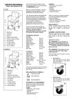
1
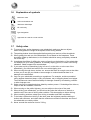
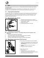
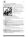
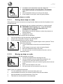
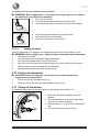
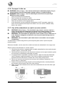
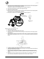
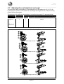
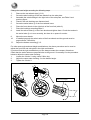
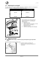
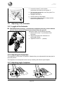
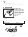
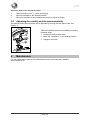
VERMEIREN
D400
INSTRUCTION
MANUAL
Instructions to the specialist dealer
This instruction manual is part and parcel of the product and must accompany every product sold.
Version: B, 2013-06
All rights reserved, including translation.
No part of this manual may be reproduced in any form what so ever (print, photocopy, microfilm or any other process) without
written permission of the publisher, or processed, duplicated or distributed by using electronic systems.
© N.V. Vermeiren N.V. 2013
D400
2013-06
Contents
Preface ................................................................................................. 2
1
Productdescription .................................................................. 3
1.1
1.2
1.3
1.4
1.5
1.6
1.7
2
Use ............................................................................................. 7
2.1
2.2
2.3
2.4
2.5
2.6
2.7
2.8
2.9
2.10
2.11
2.12
2.13
2.14
2.15
2.16
2.17
3
Carrying the wheelchair .............................................................................................. 7
Mounting the rear wheels ............................................................................................ 7
Unfolding the wheelchair ............................................................................................ 7
Mounting or removing of the footrests ....................................................................... 7
Operating the brakes.................................................................................................... 8
Mounting or removing of armrests.............................................................................. 8
Transfer in and out the wheelchair ............................................................................ 10
Correct position in the wheelchair ............................................................................ 10
Riding the wheelchair................................................................................................ 10
Moving on slopes ...................................................................................................... 10
Negotiating steps or curbs ......................................................................................... 11
Fold up the wheelchair .............................................................................................. 12
Taking off the wheels ................................................................................................ 12
Adjusting handgrips .................................................................................................. 13
Backrest cushions ...................................................................................................... 13
Transport in the car.................................................................................................... 14
Use of the wheelchair as seat in a motor vehicle ...................................................... 14
Installation and adjustment .................................................. 16
3.1
3.2
3.3
3.4
3.5
3.6
3.7
3.8
4
Intended Use ................................................................................................................ 3
Technical specifications .............................................................................................. 4
Drawing ....................................................................................................................... 5
Accessories .................................................................................................................. 5
Location identification plate........................................................................................ 5
Explanation of symbols ............................................................................................... 6
Safety rules .................................................................................................................. 6
Tools .......................................................................................................................... 16
Manner of delivery .................................................................................................... 16
Adjusting the seat height and seat angle ................................................................... 17
Adjusting the seat depth ............................................................................................ 19
Adjust the brakes ....................................................................................................... 19
Adjusting of the footrests .......................................................................................... 20
Adjusting the armpad ................................................................................................ 21
Adjusting the stability and the maneuverability ........................................................ 22
Maintenance ........................................................................... 22
Page 1
D400
2013-06
Preface
First of all we want to thank you for putting your trust in us by selecting one of our
wheelchairs.
The Vermeiren wheelchairs are the result of many years of research and experience. During
the development, special attention was given to the ease of use and the serviceability of the
wheelchair.
The expected lifetime of 8 years for your wheelchair is strongly influenced by the care and
maintenance of the wheelchair.
This manual will help you get acquainted with the operation of your wheelchair.
Following the user instructions and the maintenance instructions are an essential part of the
guarantee.
This manual reflects the latest product developments. Vermeiren has the right to introduce
changes without the obligation to adapt or replace previously delivered models.
For any further questions, please consult your specialist dealer.
Page 2
D400
2013-06
1
Productdescription
1.1
Intended Use
The wheelchair is intended for people with walking difficulties or no walking abilities.
The wheelchair is designed to transport 1 person.
The wheelchair is suited for indoor and outdoor use.
The user can propel the wheelchair by himself or have the wheelchair pushed by an
attendant.
The different types of fittings and accessories, and the modular construction allow full use by
persons disabled by:
•
•
•
•
•
•
•
•
paralysis
loss of limbs (leg amputation)
limb defects or deformations
stiff or damaged joints
heart insuffiencies and poor blood circulation
balance disturbances
cachexia (decrease in muscle)
and also for aged persons.
When providing for individual requirements:
• body size and weight (max. 130 kg)
• physical and psychological condition
• residential circumstances
• environment
should be taken into consideration.
Your wheelchair should only be used on surfaces where all four wheels are touching the
ground and where there is sufficient contact to propel the wheels equally.
You should practice for use on uneven surfaces (cobblestones, etc.), slopes, curves and to
get past obstacles (curbs, etc.).
The wheelchair should not be used as a ladder, nor is it a transport for heavy or hot objects.
When used on mats, carpeted floors or loose floor coverings, the floor covering can get
damaged.
Use only Vermeiren approved accessories.
The manufacturer is not liable for damage caused by the lack of or improper service or as a
result of not following instructions from this manual.
Compliance with the user and maintenance instructions are an essential part of the
guarantee conditions.
Page 3
D400
2013-06
1.2
Technical specifications
Technical terms below are valid for the wheelchair in standard settings.
If other footrests / armrests or other accessories are used, the tabulated values will change.
Make
Vermeiren
Address
Vermeirenplein 1/15, B-2920 Kalmthout
Type
Manual wheelchair
Model
D400
Maximum occupant mass
130 kg
Description
Dimensions Min.
Overall length with footrest
Dimensions Max.
1040 mm
Effective seat width
380 mm 400 mm 420 mm 440 mm 460 mm 480 mm 500 mm 520 mm
Overall width (depends on the seat
width)
560 mm 580 mm 600 mm 620 mm 640 mm 660 mm 680 mm 700 mm
Folded length
1020 mm
Folded width
310 mm
Folded height
900 mm
1010 mm
Total mass
17,7 kg
Mass of heaviest part
9 kg
Static stability downhill
10° (in standard configur ation)
Static stability uphill
7° (in standard configuration)
Static stability sideways
18° (in standard configur ation)
Obstacle climbing
60 mm
Seat plane angle
0°
10°
Effective seat depth
440 mm
520 mm
Seat surface height at front edge
440 mm
530 mm
Backrest angle
5°
Backrest height
400 mm
Distance between footplate and
seat
420 mm
Angle between seat and footplate
5°
25°
Angle between leg of footrest and
footplate
80°
100°
Angle between seat and leg of
footrest
Distance between armpad and seat
105°
205 mm
280 mm
Front location of armrest structure
410 mm
Handrim diameter
535 mm
Horizontal location of axle
(deflection)
1,27 mm
Minimum turning radius
Diameter PU Rear wheels
1500 mm
22"
Tyre pressure, rear (driving) wheels
200 mm
Tyre pressure, steering wheels
Storage and use humidity
24"
Max. 3.5 bar
Diameter PU steering wheels
Storage and use temperature
61,04 mm
Max. 2.5 bar
+ 5 °C
+ 41 °C
30%
70%
We reserve the right to introduce technical changes. Measurement tolerance ± 15 mm / 1,5 kg / °
Table 1: Technical specifications
Page 4
D400
2013-06
The wheelchair complies to the requirements set up in:
ISO 7176-8: Requirements and test methods for static, impact and fatigue strengths.
ISO 7176-16: Resistance to ignition of upholstered parts
1.3
Drawing
1 = Armpads
2 = Armrests
3 = Footrests
4 = Angle adjustable footplates
5 = Brakes
6 = Steering wheels (front wheels)
7 = Driving wheels (rear wheels)
8 = Hand rims
9 = Seat
10 = Backrest
11 = Tip cap
12 = Cross
13 = Adjustable handgrips
1.4
Accessories
The following accessories are available for the D400:
• Anterior pelvic belt (B20) for mounting on the tubes of the back (see according
manual)
• Anti-tipping device (B78) for mounting on the bottom frame (see according manual).
1.5
Location identification plate
1 = Logo Vermeiren
2 = Mounting safety belt according
ISO 10542
3 = Identification plate
4 = Name Vermeiren
Page 5
D400
2013-06
1.6
Explanation of symbols
Maximum mass
Indoor and outdoor use
Maximum Safe Slope
CE conformity
Type designation
Approved as a seat in a motor vehicle
1.7 Safety rules
L To prevent injury and/or damage to your wheelchair, make sure that no objects
L
L
L
L
L
L
L
L
L
L
L
L
and/or body parts are caught in the spokes of the driving wheels.
The parking brakes should be applied before getting into and out of the wheelchair.
When getting into and out of the wheelchair, do not stand on the footplates. These
should be folded up beforehand, or the footrest should be swung completely outwards
out of the way.
Investigate the effects of shifting the centre of gravity on the behavior of the wheelchair,
for example on up or down gradients, on laterally sloping ground, or when overcoming
obstacles. Obtain support from an attendant.
If you want to pick up something (lying in front of, on the side, or to the rear of the
wheelchair), you should not lean too far out to avoid tipping over.
When moving through doors, arches, etc. ensure that there is enough room at the sides
so that you do not get your hands or arms caught or crushed and that there is no
damage to the wheelchair.
Only use your wheelchair according to regulations. For example, avoid uncontrolled
rolling against obstacles (steps, curbs, doorframes, etc) or dropping down from ledges.
The manufacturer cannot assume liability for damage caused by overloading, collision
or other improper use.
Stairs may only be negotiated when aided by another person. If furnishings like drive-on,
ramps or lifts are available, use them.
When moving on the public highway, you are subject to the rules of the road.
When driving your wheelchair, you should not be under the influence of alcohol or
medicine as in the case of driving other vehicles. This also applies to indoor driving.
When travelling outdoors, adapt your driving to weather and traffic conditions.
To be better visible when driving in the dark, wear the brightest possible clothing or
clothes with reflectors, and check that the reflectors mounted on the sides and rear of
the wheelchair are clearly visible.
Never exceed the maximum load of 130 kg.
Page 6
D400
2013-06
2
Use
This chapter describes the everyday use. These instructions are for the user and the
specialist dealer.
The wheelchair is delivered fully assembled by your specialist dealer. The instructions
intended for the specialist dealer on how to set up the wheelchair are given in § 3.
2.1
Carrying the wheelchair
The best way to carry the wheelchair is to make use of the wheels and roll the wheelchair.
If this is not possible (e.g. when the rear wheels are taken off for transportation in a car),
firmly grasp the frame on the front and the grips. Do not use the foot-, armrests or the
wheels to grasp the wheelchair.
2.2
Mounting the rear wheels
1. Take the rear wheel and push on button .
2. Keep the button pushed in and mount the rear
wheels axle till it stops.
3. Release the button.
4. Check that the wheels is secured.
2.3 Unfolding the wheelchair
L CAUTION: Risk of clamping – Keep fingers away from moving parts of the
1.
2.
3.
4.
2.4
wheelchair.
Position yourself behind the wheelchair.
Use the hand-grips to open the wheelchair as much as possible.
Position yourself at the front of the wheelchair.
Push both seating tubes down till they are fixed in their position.
Mounting or removing of the footrests
The mounting of the footrests is done as follows:
1. Hold the footrest sideways at the outside of the
wheelchairs frame and mount the tube hood
into the frame.
2. Swing the footrest inwards till it clicks in
position.
3. Swing the footplate downwards.
To take off the footrests:
1. Pull handle .
2. Swing the footrest to the outside of the
wheelchair till it comes loose from the guidance.
3. Pull the footrest from tube hood .
Page 7
D400
2013-06
2.5 Operating the brakes
L WARNING: The brakes aren't used to slow down the wheelchair during
L
L
L
movements – Use the brake only to prevent the wheelchair from unintended
movements.
WARNING: Good operation of the brakes is influenced by wear and
contamination of the tires (water, oil, mud, …) – Check the condition of the tires
before each use.
WARNING: The brakes are adjustable and can wear – Check the operation of the
brakes before each use.
WARNING: Risk of clamping - Do not touch the wheelchair frame with your
hands, fingers when applying, releasing the brakes.
To apply the brakes:
1.
Push the brake handles forward till you feel a distinctive click.
L CAUTION: Risk of unintended movement – Make sure the wheelchair is on a flat
horizontal surface before releasing the brakes. Never release both brakes
simultaneously.
To release the brakes:
1.
2.
3.
Release one brake by pulling the handle backwards.
Hold the hand-rim of the release wheel with your hand.
Release the second brake by pulling the handle backwards.
2.6
Mounting or removing of armrests
The armrests of the wheelchair can be mounted by following instructions.
L CAUTION: Risk of clamping – Keep fingers, buckles and clothes away from the
bottom side of the armrest.
L CAUTION: Risk of clamping – Be careful that your fingers, hands are not
squeezed between the rear wheels and the side plate of the armrests.
1. Mount the rear tube of the armrest in tube
hood .
2. Make sure the armrest clicks in the locking
mechanism.
3. Fold the armrest forward.
Page 8
D400
2013-06
4. Click the front tube of the armrest in tube
hood .
To open and remove the armrest:
1. Press lever
and pull the front of the armrest
upwards.
2. Fold the armrest backwards.
3.
To remove the armrest, press button
tube hood .
and pull the rear of the armrest from
Page 9
D400
2013-06
2.7 Transfer in and out the wheelchair
L CAUTION: In case you cannot perform the transfer in a safe manner, ask
someone to assist you.
CAUTION: Risk of tipping over of the wheelchair – Do not stand on the foot
plates.
1. Position the wheelchair as close as possible to
the chair, couch or bed to/from you wish to
transfer.
2. Check both brakes from the wheelchair are in
the on position.
3. Fold the footplates upwards to prevent
standing on them.
4. If the transfer is on the side of the wheelchair,
fold the armrest on that side upwards
(see § 2.6).
5. Transfer to/from the wheelchair.
L
2.8
Correct position in the wheelchair
Some recommendations for a comfortable use of the wheelchair:
•
•
Position your backside as close as possible to the back rest.
Make sure your upper legs are horizontal – If needed adjust the length of the foot
rests (see § 3.6.1).
2.9 Riding the wheelchair
L WARNING: Risk of clamping – Prevent your fingers from being caught by the
L
L
L
1.
2.
3.
4.
wheels spokes.
WARNING: Risk of clamping – Prevent that your fingers, hands are clamped
between the hand rim and rear wheel.
WARNING: Risk of clamping – Be careful passing through restricted passages
(e.g. doors).
WARNING: Risk of burns – Be careful when driving in hot or cold environments
(sunshine, extreme cold, saunas, etc.) for a sufficient amount of time and when
touching - Surfaces can assume the environment temperatures.
Release the brakes.
Take both hand rims at their highest position.
Lean forward and push the hand rims forward until straight arms.
Swing your arms loosely back to the hand rims topside and repeat the movement.
2.10 Moving on slopes
L WARNING: Control your speed – Moving on slopes as slow as possible.
L WARNING: Consider the capacities of your attendant – If your attendant does not
have enough force to control the wheelchair, put on the brakes.
L WARNING: Risk of tipping over – Lean forward to move your centre of gravity
forward. To improve a better stability.
Page 10
D400
2013-06
1.
2.
3.
4.
If available on the wheelchair, wear the safety belt.
Do not attempt moving on too high slopes. The maximum
slope angles (upwards and downwards) are mentioned in
table 1.
Ask an attendant to help you moving on the slope.
Lean forward to move your centre of gravity forward.
2.11 Negotiating steps or curbs
2.11.1
Getting down steps or curbs
Riding down low curbs can be done moving forwards. Make sure that the footplates do not
touch the ground.
A practiced user can negotiate small steps or curbs by himself:
L WARNING: Risk of tipping over – If you do not have
enough experience with your wheelchair, ask
assistance of an attendant.
1. Bring balance on the rear wheels to reduce the pressure on
the front wheels.
2. Negotiate the curbs.
Higher curbs can be taken forward with an attendant:
1.
2.
3.
Ask the attendant to tip the wheelchair slightly backwards.
Get past the curbs while moving on the rear wheels.
Put the wheelchair back on the four wheels.
An experienced user can negotiate higher curbs by himself. This is
best done backwards.
1. Turn the wheelchair to have the rear wheels facing the
curb.
2. Lean forward to move your centre of gravity forward.
3. Move the wheelchair close to the curbs.
4. Use the hand rim to roll-off wheelchair from the curb in a
controlled manner.
2.11.2
Moving up steps or curbs
Moving up steps or curbs with attendant as follows:
1.
2.
3.
4.
5.
Prevent the footplates from touching the curb.
Ask the attendant to tip the wheelchair backwards, just
enough to move the front wheels over the curb.
Lean backwards to move your centre of gravity above the rear
wheel.
Place the front wheels on the curb.
Roll rear wheels of the wheelchair over the curb.
Higher curbs are negotiated backwards:
1.
2.
3.
4.
Turn the wheelchair to have the rear wheels facing the curb.
Lean backwards and move your centre of gravity above the rear wheels.
Ask the attendant to pull the wheelchair on the curb.
Take back the normal position in the wheelchair.
Page 11
D400
2013-06
An experienced user can negotiate curbs by himself:
L WARNING: Risk of tipping over – If you have not enough experience to control
the wheelchair, get help from an attendant.
1. Drive until the curbs.
2. Ensure that the footplates do not touch the curbs.
3. Lean backwards so you are balancing on the rear wheels.
4.
5.
6.
2.11.3
Role the frontwheels balancing over the curbs.
Bend forwards for more stability.
Role the rear wheels over the curbs.
Taking of stairs
Taking of stairs while you staying in the wheelchair shall be according following rules:
L WARNING: Risk of tipping over – Taking of stairs shall always with 2 attendants.
1.
2.
3.
4.
5.
6.
Remove the footrests.
One attendant tip the wheelchair slightly backwards.
The second attendant take the front of the frame.
Stay calm, avoid sudden movements and keep your arms inside the wheelchair.
Take the steps on the rear wheels of the wheelchair.
Mounting the footrests back after taking the stair.
2.12 Fold up the wheelchair
L CAUTION: Chance of pinching – Do not place your fingers between the
1.
2.
components of the wheelchair.
Fold or remove the footrests (see § 2.4).
Take the seat on the front side and backside and pull it up.
2.13 Taking off the wheels
To facilitate the transport off the wheelchair the rear wheels can be taken off:
1. Make sure the brakes standing in the off
position.
2. Take the wheelchair to the side frame where
you want to remove the wheel.
3. Press the button
in the center of the wheel
hub.
4. Pull the wheel away from the frame.
Page 12
D400
2013-06
2.14 Adjusting handgrips
L WARNING: Risk of injury – Make sure that all screws are properly tightened.
L WARNING: Risk of injury, Danger of tipping over – Make sure that the handgrips
L
on both sides are set to the same height.
WARNING: Risk of injury – Keep a safe distance from 50 mm on the bottom side
of the handgrip (in the backrest tubes).
The handgrip
is height adjustable by moving these
in the backrest tubes .
1. Loosen the star knob .
2. Move the handgrip in the desired height (Range
110 mm: stepless).
again.
3. Retighten the star knob
2.15 Backrest cushions
L WARNING: Risk of injury – Check that all straps are secured with Velcro.
The back rest cushions can be
removed or mounted with the velcro
strips on the backrest velcro straps
.
The back can be adjusted in its
flexibility, so the back of the user is
supported differently.
1. Remove the back rest cushion with the velcro . Pull the back rest cushion on
the frontside to the front, back rest cushion
comes from the velcro straps . Pull
the back rest cushion on the back side backwards. Now you can see the
suspension system with straps that can be adjusted independently.
2. Loosen the velcro closures of the respective straps .
3. Pull the respective strap to the desired position, the tension of the individual belts
can be varied and the desired support of the back can be set.
4. Replace the back rest cushion .
Page 13
D400
2013-06
2.16 Transport in the car
L WARNING: Risk of injury – See that the wheelchair is attached properly. So you
L
1.
2.
3.
4.
5.
can avoid injury from the passengers during collision or sudden braking.
WARNING: Risk of injury – Use for attaching the wheelchair and passenger
NEVER the same seatbelt.
Remove footrests and accessories.
Store footrests and accessories safely.
If possible, fold the wheelchair and remove the wheels.
Place the wheelchair in the luggage place.
If the wheelchair and the passenger compartment is NOT separated, attach the
frame of the wheelchair securely to the vehicle. You can use the available safety
belts in the vehicle.
2.17 Use of the wheelchair as seat in a motor vehicle
L
WARNING: Risk of injury - The wheelchair may only be used as a seat in a
L
L
motor vehicle when the handgrips are placed in the lowest position. In other
cases it is forbidden to use the wheelchair as a seat in a motor vehicle.
WARNING: The wheelchair has passed the crash of ISO 7176-19: 2008 and, as
such, has been designed and tested for use only as forward-facing seat in a
motor vehicle.
WARNING: The wheelchair's pelvic belt alone is not suited as an occupant
restraint belt.
The wheelchair is tested using the four-point strap-tie system and a 3-point occupantrestraint system.
Whenever feasable, use the seat of the vehicle and store the wheelchair in the cargo area.
Steps to secure the wheelchair in a motor vehicle:
1. Check that the vehicle is equipped with a suitable wheelchair tie down and occupantrestraint system, conform ISO 10542.
2. Check that the components of the wheelchair tie down and occupant restraint system
are not frayed, contaminated, damaged or broken.
3. If equipped with an adjustable seat and/or back tilt, make sure that the wheelchair
user is sitting as upright as possible. If the user's condition prevents this, a risk
assessment should be done to evaluate the user's safety during transit.
4. Remove all mounted accessories such as trays and respiratory equipment, and
secure them in a safe place.
5. Position the wheelchair facing forward in the travelling direction, centrally between
the tie-down rails mounted in the floor of the vehicle.
6. Make sure that the indicated zones around the wheelchair user are clear from rigid
vehicle parts.
Page 14
D400
2013-06
7. Mount the front securement straps according to the instructions of the strap-system
manufacturer at the indicated place. (figure 3)
This place is marked on the wheelchair with a symbol. (figure 4)
8. Roll back the wheelchair until the front straps are tight.
9. Apply the wheelchair brake.
10. Mount the back securement straps according to the instructions of the strap-system
manufacturer at the indicated place. (figure 3)
11. This place is marked on the wheelchair with a symbol. (figure 4)
Handgrips in
lowest position
figure 3
Steps to secure the wheelchair user:
1. Remove both arm rests.
2. If present, attach the wheelchair's pelvic belt.
3. Attach the occupant restraint belts according to the instructions of the strap-system
manufacturer.
4. Wear the pelvic belt low across the front of the pelvis, so that the angle of the pelvic
belt is within the preferred zone of 30° to 75° to the horizontal, similar to that shown
below.
5. A steeper (greater) angle within the preferred zone is desirable.
6. Adjust the belt tightly according to the instructions of the strap-system manufacturer,
consistent with the user's comfort.
7. Ensure that the restraint belt connects in a straight line to the anchor point in the
vehicle and that no bends in the belt are visible, for instance at the axle of the rear
wheel.
8. Install the arm rests, if desired. make sure that belts are not twisted or held away
from the body by wheelchair components such as arm rests or wheels.
Page 15
D400
2013-06
3
Installation and adjustment
The instructions in this chapter are for the specialist dealer.
The Vermeiren D400 has been designed to be adjust with a minimum of replacements parts.
There is no need for extra stock of spare parts.
To find a service facility or specialist dealer near you, contact the nearest Vermeiren facility.
A list of Vermeiren facilities can be found on the last page.
L WARNING: Risk of unsafe settings - Use only the settings described in this
manual.
L WARNING: Variation of allowed adjustments can still change the stability of your
wheelchair (tilt back or sideways).
3.1
•
•
•
•
3.2
Tools
Wrench set n° 7 to n° 22
Allen keyset n° 3 to n° 8
Screwdriver n° 4 to n° 5
Screwdriver Phillips head
Manner of delivery
The Vermeiren D400 shall be delivered with:
• 1 frame with armrests, rear and front wheels (standard delivery seat height: 500 mm,
seat angle: 5°)
• 1 pair footrests
• Tools
• Manual
• Accessories
Page 16
D400
2013-06
3.3
Adjusting the seat height and seat angle
The Vermeiren D400 is adjustable in 4 seat heights and 5 seat angles (0°-2,5°-5°-7,5°-10°)
by changing the position of the wheels for each height and angle there is a different setting
of the front and rear wheels.
The summary of the different seat heights by a standard seat angle 5° is tabulated below.
Seat height Rear wheels
Hole
Front wheels
Hole Bushing Ⓑ relative to castor stem housing Ⓒ
440 mm
Above
470 mm
Under
500 mm
(Standard)
Under
530 mm
Under
Table 2: Seat heights by seat angle 5°
Axle plate rear wheels
Front wheel
Seat height 440 mm
Seat height 470 mm
Seat height 500 mm (Standard)
Seat height 530 mm
Page 17
D400
2013-06
Change the seat height according the following steps:
1.
Remove the rear wheels (see § 2.13).
2.
Screw the axle bushings of the rear wheels from the axle plate.
3.
Assemble the axle bushings in the right hole of the axle plate, see Table 2 and
previous figure.
4.
Check if the axle bushings are fastened well.
5.
Screw the swivel axles Ⓐ of the front wheels loose.
6.
7.
Place the front wheels in the right hole of the front fork (table 2).
Place the bushings according table 2.
8.
Install the swivel axles Ⓐ of the front wheels and tighten them. Check the tension in
the swivel axle Ⓐ so it turn smoothly, but there is no space for motion.
9.
10.
11.
Mount the rear wheels.
If installed properly the swivel axles of the front wheels and the ground must be
perpendicular. Check this.
Adjust the brakes according § 3.5.
For other seat angle and seat height combinations, the above procedure can be used to
adjust the front fork and axle plate in the right combination.
If you don't find the right combination you can always contact the company Vermeiren.
Check that the swivel axles are perpendicular to the ground. If necessary use the procedure
below to adjust the castor stem housing:
1.
Loosen the 3 bolts using a size 5 Allen key.
2.
Adjust the castor stem housing to the desired angle.
3.
Tighten the 3 bolts .
Indication 5 angle
positions (triangle)
Page 18
D400
2013-06
3.4
Adjusting the seat depth
The seat depth of the Vermeiren D400 is adjustable in 5 different positions by changing the
backrest connection Ⓐ (Range 80 mm in steps from 20 mm).
Seat depth
Backrest connection Ⓐ to
position at seat frame
440 mm (Standard)
Position 1
460 mm
Position 2
480 mm
Position 3
500 mm
Position 4
520 mm
Position 5
Table 3: Seat depth
The seat depth can be changed by the
backrest connection Ⓐ according the
following steps:
1. Remove the bolts.
2. Move the back rest connection in the
desired position (see table 3).
3. Retighten the bolts.
4. Check the seat height and seat angle.
3.5 Adjust the brakes
L WARNING: Risk of injury – Brakes may only be adjusted by your specialist
dealer.
Adjust the brakes according following rules:
1. Install the wheels according § 2.2.
2. Disconnect the brakes by pulling lever
backwards.
Page 19
D400
2013-06
2
3.6
3
3. Loosen the bolts
so the brake
mechanism can slide over the guide .
4. Pull the brake mechanism over the guide
to
the desired position.
5. Retighten the bolts .
6. Check working of the brakes.
7. If necessary repeat the above steps until the
brakes are adjusted well.
Adjusting of the footrests
3.6.1 Length of the footrests
L CAUTION: Risk of damage – Avoid that the footplates make any contact with the
ground. Keep a minimum distance from 60 mm above the ground.
Adjust the length of the footrests as follow:
1. Remove the screw
(on the back of the
footrests).
2. Adjust the length of the footrests to a
comfortable length.
3. Tighten the screw
properly.
3.6.2 Adjusting the footplates
The footplates can be used in 2 positions. Standard they are adjusted with the base plate in
the back position.
The footplates can be adjusted to the front by switching the left and right footplate.
3.6.3 Adjusting angle footplates
100°
80°
Page 20
D400
2013-06
Adjust the angle of the footplates as follow:
1.
Loosen bolt .
2.
Adjust tube in the desired angle. The angle indication (80°-85 °-90°-95°-100°) is
according the dashes .
3.
Retighten the bolt .
3.7
Adjusting the armpad
The armpad of your wheelchair can be adjusted in height and depth. The height of the
armpad can be adjusted in 6 positions (Range 75 mm in steps from 15 mm).
Adjust the height and depth of the armpad as
follow:
1. Loosen the locking mechanism slightly by
turning the star knob Ⓐ anti-clockwise.
2. Pull on the locking pin Ⓐ.
3. Move the armpad, to adjust the height of
the armpad. Do this at the same time when
pulling on the locking pin Ⓐ.
4. Let go of the locking pin Ⓐ.
5. Check that the locking pins Ⓐ are
securely fixed.
6. Retighten the locking mechanism by turning the star knob Ⓐ clockwise to reduce the play
of the armpad.
The depth of the armpad can be adjusted in 3 positions (steps: 42,5 mm).
Depth of the armpad
Used holes
Front position
Back and middle
Middle position (Standard)
Hole 2 and 4
Back position
Front and middle
Table 4: Depth of armrest
Page 21
D400
2013-06
Adjust the depth of the armpad as follow:
1.
Remove both screws Ⓐ under the armpad.
2.
Adjust the armpad in the desired position.
3.
Mount the armpad on the corresponding holes to adjust the depth.
3.8
Adjusting the stability and the maneuverability
The stability and maneuverability can be adjusted by moving the axle plate of the rear
wheels .
Adjust the stability and maneuverability according
following steps:
1. Loosen the bolts of axle plate.
2. Move the axle plate in the desired position.
3. Retighten the bolts.
4
Maintenance
For the maintenance manual of the wheelchairs refer to the Vermeiren website:
www.vermeiren.be.
Page 22
D400
2013-06
SERVICE
The manual wheelchair was serviced:
Dealer´s stamp:
Dealer´s stamp:
Date:
Date:
Dealer´s stamp:
Dealer´s stamp:
Date:
Date:
Dealer´s stamp:
Dealer´s stamp:
Date:
Date:
Dealer´s stamp:
Dealer´s stamp:
Date:
Date:
Dealer´s stamp:
Dealer´s stamp:
Date:
Date:
•
For service checklists an additional technical information, please see our specialist dealers nearest to you.
More information on our website at: www.vermeiren.com.
Notes
....................................................................................................................................................
....................................................................................................................................................
....................................................................................................................................................
....................................................................................................................................................
....................................................................................................................................................
....................................................................................................................................................
....................................................................................................................................................
....................................................................................................................................................
....................................................................................................................................................
....................................................................................................................................................
....................................................................................................................................................
....................................................................................................................................................
....................................................................................................................................................
....................................................................................................................................................
....................................................................................................................................................
....................................................................................................................................................
....................................................................................................................................................
....................................................................................................................................................
....................................................................................................................................................
....................................................................................................................................................
....................................................................................................................................................
....................................................................................................................................................
....................................................................................................................................................
....................................................................................................................................................
!
Germany
N.V. Vermeiren N.V.
Vermeirenplein 1 / 15
B-2920 Kalmthout
Tel: +32(0)3 620 20 20
Fax: +32(0)3 666 48 94
website: www.vermeiren.be
e-mail: [email protected]
Vermeiren Deutschland GmbH
Wahlerstraße 12 a
D-40472 Düsseldorf
Tel: +49(0)211 94 27 90
Fax: +49(0)211 65 36 00
website: www.vermeiren.de
e-mail: [email protected]
France
Austria
Vermeiren France S.A.
Z. I., 5, Rue d´Ennevelin
F-59710 Avelin
Tel: +33(0)3 28 55 07 98
Fax: +33(0)3 20 90 28 89
website: www.vermeiren.fr
e-mail: [email protected]
L. Vermeiren Ges. mbH
Winetzhammerstraße 10
A-4030 Linz
Tel: +43(0)732 37 13 66
Fax: +43(0)732 37 13 69
website: www.vermeiren.at
e-mail: [email protected]
Italy
Switzerland
Reatime S.R.L.
Vermeiren Suisse S.A.
Viale delle Industrie 5
I-20020 Arese MI
Tel: +39 02 99 77 07
Fax: +39 02 93 58 56 17
website: www.reatime.it
e-mail: [email protected]
Hühnerhubelstraße 59
CH-3123 Belp
Tel: +41(0)31 818 40 95
Fax: +41(0)31 818 40 98
website: www.vermeiren.ch
e-mail: [email protected]
Poland
Spain
Vermeiren Polska Sp. z o.o
ul. Łączna 1
PL-55-100 Trzebnica
Tel: +48(0)71 387 42 00
Fax: +48(0)71 387 05 74
website: www.vermeiren.pl
e-mail: [email protected]
Vermeiren Iberica, S.L.
Trens Petits, 6. - Pol. Ind. Mas Xirgu.
17005 Girona
Tel: +34 902 48 72 72
Fax: +34 972 40 50 54
website: www.vermeiren.es
e-mail: [email protected]
Czech Republic
Vermeiren ČR S.R.O.
Sezemická 2757/2 - VGP Park
193 00 Praha 9 - Horní Počernice
Tel: +420 731 653 639
Fax: +420 596 121 976
website: www.vermeiren.cz
e-mail: [email protected]
R.E.: N.V. Vermeiren N.V., Vermeirenplein 1/15 - 2920 Kalmthout - Belgium – 2013-06- Instruction Manual D400- vB
Belgium