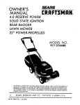
1
®
MODELNUMBER
917o374711
Assembay
Operation
Customer
ResponsibRaities
Service
Adjustments
Repair Parts
.aUtlOn.
%
m
=
_ead and Follow
_!1Safety Rules
md Instructions
3efore Operating
I'his Equipment
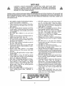
AL
SAFETY
RULES
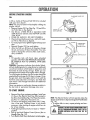
CAUTION:
ALWAYS
DISCONNECT
SPARK PLUG WIRE AND
WHERE IT CANNOT
CONTACT
SPARK PLUG TO PREVENT
STARTING WHEN SETTING-UP,
TRANSPORTING,
ADJUSTING
REPAIRS TO YOUR LAWN
MOWER..
PLACE 'WIRE
ACCIDENTAL
OR MAKING
OMPOBTANT
FEDERAL REGULATIONS
REQUIRE OPERATOR PRESENCE BLADE STOP CONTROLS
TO MINIMIZE
THE
RISK OF BLADE CONTACT
INJURY.. YOUR LAWN MOWER
IS EQUIPPED WITH SUCH CONTROLS.
DO
NOT ATTEMPT TO DEFEAT THE FUNCTION
OF THE OPERATOR
PRESENCE CONTROL
UNDER ANY
CIRCUMSTANCES.
o BE CAREFUL-WHEN
NING THE BLADE
THE ENGINE
IS TURNING
o Please read your owner's
manual.
IS RUNOnly allow
persons who know the safety rules to use your
lawn mower°
o DO NOT tie the operator presence control bar
to the handle. Control must be free to permit
brake engagement
when handles and control
are released..
o
o
o
o
o
o
o
o
o
o
e
o
DO NOT allow children to use your' lawn
mower.
Check your lawn mower over before each use_
Tighten any loose bolts, nuts, etc._
Remove all sticks, stones, wires, cans, boards,
etc. from area to be mowed. These objects can
be thrown by the blade..
DO NOT allow children, bystanders or pets in
the area while mowing..
Always wear shoes when mowing. DO NOT
operate lawn mower when barefoot or wearing open sandals.
Always
wear safety glasses or eye shields
before starting your lawn mower and while
mowing.
Always shut off engine before trying to adjust
whee/heights_.
When engine is running, DO NOT put hands
or feet under lawn mower or' in the discharge
chute, nor make any adjustments°
Stay clear' of discharge opening at all times_
Do not fill gas tank when engine is running,
when indoors or when engine is hot. Allow
engine to cool for' several minutes before filling gas tank° Clean off any spilled gasoline
before starting engine.
Mow only in goodlighto
Always stop blade when not cutting grass or
when crossing gravel
drive,
sidewalk,
or
roadway°
o
o
°
o
o
o
o
o
o
o
o
o
DO NOT continue to run your lawn mower if
you hit a foreign
object_ Stop the engine,
disconnect the spark plug wire from the spark
plug, inspect the lawn mower for damage and
make repairs as required.
DO NOT use a damaged lawn mower. Always
have damage repaired
before mowing.
DO NOT run your lawn mower if it vibrates
too much_ Stop engine and make repairs_
Vibration
is an indication
of damage.
Never use your lawn mower without proper
guards or deflectors
in place_
Always mow across a slope or inclined area.
DO NOT mow up or down a slope or inclined
area.
DO NOT mow in wet grass. Be careful of
footing when mowing in wet grass, use shoes
with good traction_
DO NOT run with the lawn mower°
DO NOT run your lawn mower indoors_ Exhaust gases are deadly poison.
Always disconnect the engine connector from
the battery connector' and the spark plug wire
from spark plug to prevent accidental starting
when transporting
or storing your lawn mower
after the mowing season_
DO NOT attempt to raise engine speed, above
factory settings.. Engine damage or personal
injury may result.
if a grass catcher' is used on your lawn mower,
check the catcher
often
for damage
or
deterioration_
it will wear through normal use_
Use only a recommended replacement catcher.
Always stop blade to remove or install catcher..
DO NOT store your lawn mower or gasoline
where fumes may reach an open flame and
cause a fire.
o DRAIN
THE GASOLINE
from your lawn
mower before transporting
your lawn mower
inside your car or other vehicle_
LOOK FOB THIS SYMBOLTO POINT OUT IMPOR,_
TION!!J
BECOME
ALERT!!f YOUR
SAFETY IS
TANT
SAFETY
PRECAUTIONS.IT
iREAEIS--ATTENINVOLVED.
PRODUCTSPECnFICATBONS
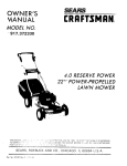
CONGRATULATIONS
on your
purchase of a Sears Craftsman
Lawn
Mower.
it has been
designed,
engineered
and manufactured
to give you the best
possible dependability
and performance°
Should you experience any problem you cannot easily remedy, please contact your nearest Sears Service Center/Departmento
We have competent, welltrained technicians and the proper tools to service
or repair this unit°
Please read and retain this manual°
will enable you to assemble
mower properly°
Always
RULES"_
HORSE
The instructions
POWER:
5.0
DISPLACEMENT:
10.49
GASOLINE
10 quart.,
(umeaaea!
CAPACITY:
OIL (21 oz_ Capacity):
cu. in,
SAE 30 or
(SAE10W30)
and maintain your lawn
observe the "SAFETY
SPARK
PLUG
(GAP
VALVE
CLEARANCE:
030
ira):
Champion
RN4C or
Sears
STD 360951
MODEL
NUMBER 917.374711
SERIAL
NUMBER
DATE OF
PURCHASE
illl,
THE MODEL AND SERIAL NUMBERS WILL BE
FOUND ON A DECAL ATTACHED TO THE REAR
OF THE LAWN MOWER HOUSING
Intake:
Exhaust:
.004
004
ink
ino
.............
SOLID STATE IGNITION
AIR GAP:
.0125
ino
BLADE
35-40
ft,dbs_
BOLT TORQUE:
YOU SHOULD RECORD BOTH SERIAL NUMBER
AND DATE OF PURCHASE AND KEEP IN A SAFE
PLACE FOR FUTURE REFERENCE.
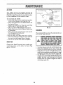
MARNTENANC[
AGREEMENT
A Sears Maintenance
Agreement
is available
on this product_
Contact
your
nearest
Sears store for details
CUSTOMER
RESPONSUBILfflES
•
o
Read and observe the safety rules.
Follow a reflular_ schedule in maintaining,
caring for and usingyour
lawn mower
Follow the instructions under
Maintenance
and
Storage
sections of this Owner
tl
II
It
II
I
s Manual.
TWOYg:ARLRMITED
WARRANTY
gN CRAFTSMAN
POWERMOWF.R
For two years Fromthe date of purchase, when this Craftsman Lawn Mower is maintained, lubricated and tuned_
up according to the instructions in the owner's manual, Sears will repair, free of charge, any defect in material
and workmanship
If this Craftsman Lawn Mower is used for commercial
days from the date of purchase,
This warranty
or rental purposes, this warranty
applies For only 90
does not cover:
Expendable items which become worn during normal use, such as rotary mower blades, blade adapters,
belts, air cleaners and spark ptug.
Repairs necessary because of operator abuse or negligence, including bent crankshafts and the failure to
maintain the equipment according to the instructions contained in the owner's manual.
WARRANTY
SERVICE IS AVAILABLE BY RETURNING THE CRAFTSMAN POWER MOWER
NEAREST SEARS SERVICE CENTER/DEPARTMENT iN THE UNITED STATES. THIS WARRANTY
ONLY WHILE THIS PRODUCT 1S IN USE IN THE UNITED STATES.
This warranty
to state
TO THE
APPLIES
gives you specific legal rights, and you may also have other rights which may vary from state
Sears, Roebuck and Company,
D/731CR_W,
Sears Tower, Chicago,
IL
60684
TABLE
OFCONTENTS
SAFETY RULES .......
PRODUCT SPECIFICATIONS
CUSTOMER RESPONSIBILITIES
WARRANTY..
LAWN MOWER ACCESSORIES
ASSEMBLY
OPERATION.
•
MAINTENANCE
....
2
3
3
3
5
.6.8
.9-13
14-16
SERVICE AND ADJUSTMENT
STORAGE
.........
.....
SERVICE RECOMMENDATIONS
17-19
20
21
REPAIR
PARTS-LAWN
MOWER ..... 22-25
REPAIR PARTS-ENGINE
.....
26-29
TROUBLE SHOOTING
....
PARTS ORDERINGISERVlCE
31
Back Cover
UNDEX
A
Adjustments:
Carburetor
Handle Height
Height of Cut
Air Filter:
Replacement
Assembly:
Battery.
Grass Catcher
Accessories
Blade:
Replacement
Sharpening
Controls:
Engine Speed Control
Engine Zone Control
Customer Respopsibitities
Cutting Levels
H
18
19
11
Handle:
Adjustment
Assembly
19
6,7
Lubrication:
Brake Spring Bracket
Drive Pawls
Drive Pinions
Engine
Handle Bracket Mounting
Rear Door Hinge
21
2|
21
2]
21
21
16
8
7
5
Pin
14
14
10
10
.3
11
Maintenance:
Agreement
Air Filter'
Blade Care/Replacement
Engine
Grass Catcher
Lubrication
Spark Plug
Mowing Tips
.3
16
14
15
15
21
16
t3
Safety Rules
Service and Adjustments:
Carburetor
Drive Belt
Drive Controi
Engine Speed
Handle .
Rear Deflector .
Speed Control Range
Service Recommendation
Spark Plug
Specifications
Speed Control:
Engine
Starting the Engine
Stopping Your Lawn Mower
Storage
Fuel:
Capacity
Type
Storage
15
12
12
t2,1s
2O
Oil:
Engine
Storage
Operation:
Operating Lawn Mower
Options:
Attachments
t5
20
9-13
5
R
.3
12
20
Repair/Replacement Parts
Responsibilities, Customer
22-25
3
1B
17
T8
19
t9
19
18
21
16
3
10
12,13
13
20
T
Trouble Shooting Chart
W
Warranty
Engine:
Oil Change
Oil Level
Oil Type
Star_ing
Storage
2
31
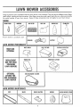
These accessories were available when this lawn mower was produced_ They are also available
at most Sears
retail outlets, catalog and service centers. Most Sears stores con order repair parts for you, when you provide
the model number of your lawn mower_ Some of these accessories may not apply to your lawn mower_
ENGINE
SPARKPLUG
If lawn
mower
MUFFLER
is an electric
AIR FILTER
GASCAN
ENGINEOIL
STABILIZER
start
BATTERY
i CHARGER
LAWNMOWERPERI:OR_ANCE
DUSTSHIELD
REARBAG
OPTIONAL
REPLACEMENT
BAG[OR REAR
D_SCHARGE
LAWN_OWERS
OPTIONAL
CATCHER
FOR
S_DEDISCHARGE
LAWNMOWER
LEAFCATCHER
FABRICBAG
CLIPPING DEFLECTOR
PER_ANEX CATCHER
1
SIDE DISCHARGECATCHER
LAWNMOWER_A_NTENANCE
BELT
BLADE
BLADEADAPTER
WHEELS
LAWN _OWER COVER
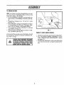
Your Craftsman Lawn Mower requires some assembly to prepare for use. Follow the instructions under "HOW
'TO SET-UP YOUR LAWN MOWER"
to complete the required assembly of Handles and Grass Catcher_
The Handles and Grass Catcher are shipped unassemble&
A 3/4" socket or adjustable
wrench is needed to
attach Handle to your lawn mower_.
TO
LAWN
C Rl'g
HANDLE
o Cut down the corners of the carton and lay ends
and sides dowm
DRIVE
o Cut the plastic wrapping
holding the Grass Cat_
cher, Catcher Frame and customer package,
remove and lay aside.
o Cut the remaining plastic wrapping
holding the
Handles.
o
o
o
o
Remove the Lower Handle and lay aside.
Lift up the Upper Handle with the Control Bars
and Speed Control and lay out behind the lawn
mower (See Fig_ 1).
Remove Engine Cover and discard°
Lift up the lawn mower and slide shipping base
from underneath
lawn mower'.
LDER
ENGINE
:ONTROL
BRACKET
HANDLE
./
Brackets
HANDLE
with the Adjuster
Brackets down (See Fig_ 2).
o Remove the Shoulder' Bolts and Washers from the
NUT
\
\,
customers package_.
o Install a Shoulder Bolt into the hole in the Lower
Handle, placing a Washer between the Lower
Handle and Handle Bracket.
o Start threads on the Shoulder Bolt into the Nut
SHOULt
located on the inside of Handle Bracket (See Fig.
2). Do this for both sides of lawn mower.
o Tighten the two (2) Shoulder Bolts with the 3/4
socket or' adjustable
wrench.
o Raise Handle and put the center hole of the Height
Adjusting
Levers over the Pins on the Adjusting
Brackets (See Fig. 3)_
To install the Adjusting Levers over the Pins, push
in on the Lever toward center' of lawn mo,_,er until the Lever clears the Pin and release to lock in
place.
e Check to be sure that the Pins and
securely
side.
8OLTS
BAR
FIG. 1
ADJUSTER
Place the Lower Handle over the Handle
BAR
UPPER
HOWTO S T4JPYOg L WN
o
CON1 ROL
BRACKET
NDLE
BRACKET
FIG. 2
HANDLE
BRACKET
DETENTS
Levers are
in place, and in the same holes an each
HEIGHT
ADJUSTING
LEVER
o
Remove the two (2) Handle Knobs and Bolts from
upper part of Lower Handle (See Fig. 4).
• Place the Upper Handle onto the Lower Handle,
then put the two (2) Handle
Bolts through
Handles, and install and tighten the Handle Knobs
(See Fig. 4)_
o Remove the six (6) Wire Ties from the customer
package.
• See Fig. 4 for' the following
wire tie installation.
FIG. 3
6
HOWTO SET-UPYOURLAWNMOWER
(CONT'D)
•
Route the Wire Harness (electric,,*,,ires inside black
tubing) to fit along underside of top part of Lower
Handte_ insta!l one (1) Wire Tie around
the
Handle and Harness at the left end of the Instruction Decal_ Leave some loop in the Harness on
the right side so that if the Upper Handle is folded down the Harness will not be stretched.
Install one (1) Wire Tie around the Upper Handle, Cables and Wire Harness 2 !/2 inches below
the Speed Control.
o Instal|two
(2) Wire Ties on the left side of Lower
Handle over Cables and Wire Harness_
ROP_
GIJIDE
o
o
o
14A_OL_ /
Install one (1) Wire Tie on the right side of Lower
Handle above the Cable Adjusten
Install one (1) Wire Tie bebw the Handle Adjuster
BrackeL
o
When all six (6) Wire Ties are installed and
tightened in place, use a pair of wire cutting pliers
or sharp knife to cut off the excess ends of Wire
Ties.
o
Check the Handle for a height that is comfortable
for you.
If the center position is not comfortable
for you,
refer to the "Adiust Handle Section" on page 19
of the manua_ for Handle adjustment°
•
LOWER
FIG. 4
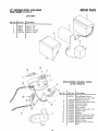
TO ASSEMBLEGRASSCATCHER
o The Catcher Frame is shipped inside the Grass
Catcher, but not assembled.
o To assemble the Grass Catcher to the Catcher
o
Frame, open the edges of the Plastic Clips and
slip over the Catcher Frame as shown in fig. 5.
Assemble the Top anct Bottom Clips first, then
assemble the Side Clips..
TO ATTACHGRASSCATCHER
°
Lower
the Grass Catcher
with Frame under the
FIG. 5
Handles at the rear of your lawn mower.
o Open the Rear Door (red door with knob) and
hold open as shown in fig. 6_.
o Lift up the Catcher and atign the Lu3s on the Catcher Frame with the Slots in the top rear of Housing as shown in fig. 6
o Slide the Grass Catcher down into the Slots and
the Retainers at the bottom rear corners of Hous•
ing (See Fig. 6).
If Bottom Retainers are not engaged, the Catcher
may swing open at the !?ottom_
CAUTION: DO NOT RUN YOUR LAWN MOWER
WITHOUT CLIPPINGDEFLECTOR
OR APPROVED
GRASSCATCHERIN PLACE.NEVERATTEMPTTO
OPERATETIlE LAWN I_OWER WITH THE REAR
DOOR REEIOVEDOR PROPPEDOPEN.
1
FIG. 6
_OTE:YourBatterymustbe chargedbeforeyoustart
your lawn mower.The Batterydoesnot haveto be
removedto plug in the charger.
Connectthe BatteryCharger,includedwith your
lawn mower,to the BatteryConnector(SeeFig°
1 10 VOLT_
A C. OUTLET
o PlugBatteryChargerinto a 1t0 volt A_C.outlet
(See Fig_7).
o Leavethe BatteryChargerconnectedfor 24 hours
to chargeBatterythe firsttime_TheEngineAlternator will not charge a discharged Battery_
•
•
Your
your
After
tery
CONNECTOR
CHARGER
engine has a built-in Alternator
to recharge
Battery during use_
charging, connect Engine Connector to BatConnector
(See Fig. 7)_
CHARGER
CONNECTOR
FIG. 7
THINGS TO CHECKBEFOREMOWING
At the end of the mowing season the Battery should
be charged for 48 hours to protect the Battery during winter storage.
CAUTION:ALWAYSDISCONNECT
THEEflGINE
TO PREVENTACCIDENTAL
CONNECTOR
FROMTHEBATTERY
STARTINGWHEN
CONNECTOR
TRANSPORTINGOR STORING YOUR LAWN
.
MOWER AFTERTHE _OWIflG,,,SEASON,,.,
o
o
The Drive Control has provisions for adjustmenL
See "TO ADJUST DRIVE CONTROL"
section
under "SERVICE AND ADJUSTMENTS"
section
on pages 18.
o Checking this adiustment is only a precaution
your new lawn mower is properly
prepared
use.
that
for
_:: ........... J
,_J_ ............ ,_;;;:_.-_:
:; ..........
_::::::_-.:::_:_.----...:_ .............
_:_-_-:-_-:...-_._:,-_
..........
--:._
:::::_-_
......... -.,,,,_._:_:_;_4_-<>--z;_.---_-_:-_;-_:_,_
-:¸:
;
;;:_:_-_.-._..._.,_._-.o_:_:_:_J_±'-
_"_"_"_LJ:_<::_-._--¸
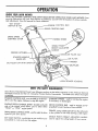
KNOWYOURtAWN MOWER
READ THIS OWNER'S
MANUAL
AND SAFETY RULES BEFORE OPERATING
YOUR LAWN MOWER.
Compare the illustrations
with your Lawn Mower to familiarize
yourself with the location of various controls
and adjustments_ Save this manual for future reference_
"KEY
START"
SWITCH
& KEY
_INE CONTROL
DRIVE
DRIVE SPEED
CONTROL
LEVER
-._------'-
CONTROL
HANDLE
SINGLE
HEIGHT
GRASS
BAR
BAR
KN
POINT"
ADJUSTER
_"
HANDLE
CATCt
GASOLINE
STARTER HANDLE
(BACK-UP}
FILLER
AIR
CAP
FILTER
PRIMER
OIL
FILLER
CAP
WITH
DIPSTICK
MUFFLER
LAWN
MOWER
HOUSING
FIG. 8
¢?S( S F TY RE g REN NTS
Sears Rotary Walk-Behind
Power Lawn Mowers conform to the safety standards of the American
National
Standards
Institute and the U_S. Consumer Product Safety Commission.
The blade turns when the engine
is running. ..........
ENGINE
CONTROL
BAR - must be held up to the bandle to start the engine,. Release to stop the engine°
" ENGINE
SPEED CONTROL LEVER - located on the left
side of the engine which allows you to select either
"HIGH"
or "LOW"
engine speed.
DRIVE SPEED CONTROL
speed
of your
lawn
LEVER - used to select the drive
STARTER HANDLE - used for starting
if the battery is discharged,
DRIVE CONTROL
propelled
forward
the engine.
BAR - used to engage
motion of lawn mower.
power-
PRIMER- pumps additional
fuel from the carburetor
to the cylinder for use when starting a cold engine..
mower._
SINGLE
KEY START SWITCH - turn this key as you would on your
automobile
to crank and start the engine,
POINT
HEIGHT
used to adjust the cutting
ADJUSTER
height
of lawn
HANDLEmower.,
ENGINESPEEDCONTROL
ENGINE SPEED
CONTROL LEVER
The engine speed is controlled
located
by a lever (red knob)
on the left side of the engine (See Fig. 9).
E_GNE ZOHECOHTROL
CAUTIOH: FEDERALREGULATIOHS
REQUIREAN
EHGt_E COHTROL TO BE INSTALLEDOF] THIS
LAW_ NOWER IH ORDER TO MIHI_IZE THE
RISK OF AEIY
BLADE
COHTACTIHJURY.
DO HOT
UHDER
CIRCUMSTANCES
ATTEMPT
TO
DEFEAT THE FUNCTIOH OF THE OPERATOR
CONTROL.THEBLADETUR_SWHEN THEEHGIHE
iS RU_NIHG.
PRIMER
,_"
FIG 9
Your lawn mower is equipped with an Operator
Engine Control Bar which requires the operator
to be positioned
behind the Lawn Mower Handle to start and operate the lawn mower (See Fig.
9).
DR1VE
SELECTOR
GROUHD DRIVE SIR SPEEDS
LEVER
\
Your lawn mower provides six (6) speeds to let you
select the speed that suits you best°
o The Speed Selector Lever can be changed while
you are mowing°
o Speeds ], 2, and 3 are found when the Engine
Speed Control (red) Lever' is in "LOW"
position
(See Figs. 9 & 10)_
o Speeds 1, 2, and 3 are for slower, light grass cuttin g, trimming, and quiet o p eration o
,, Speeds 4, 5 and 6 are found when the Engine
Speed Control (red) Lever is in "HIGH"
position
(See Figs. 9 & 10)o
Speed 4 is for stow, heavyhhick
grass cutting or
trimming.
• Speed 5 is for normal cutting and bagging.
o Speed 6 is for bagging
dried clippings
and
ground transporL
IMPORTANT: DO NOT ATTEMPT TO SHIFT SPEEDS
WITH THE DRIVE BAR ENGAGED
UNLESS THE ENGINE IS RUNNING.
ELECTRIC
START
KEY
FIG. 10
DRIVE CONTROL BAR
\_
ENGINE CONTROL
BAR
EN(
DISENGA
" " :
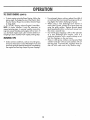
FIG. ! i
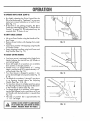
TO OPERATE
DRIVESYSTEM
o The ground speed may be selected either when
standing or moving.
• To start forward motion, slowly pull Drive Control Bar to the Handle (See Fig. 11).
o To slow or' stop forward motion let the Drive Control Bar move forward away from Handle,
o To stop forward motion release Drive Control Bar
(See Fig. 11).
o Select ground speed by moving Drive Speed
Selector Lever to 1-3 or 4-6 position and selecting either HI or LOW engine speed.
1-3 is slower and 4-6 is faster'.
10
TO OPERATE DRIVE SYSTEM (COHT'D)
o
o
By slightly releasing the Drive Controt Bar the
Drive can be slowed or "feathered"
so you may
make turns around obstacles or at end of rows
(See Fig° 1!)_
If the Drive is not pulling properly,
the Drive
Cable may need adjusting (see "To Adjust Drive
Control"
on page t8). This adjustment may be
required
after 15 hours of use.
TO EMPTYGRASSCATCHER
o
Lift up on Grass Catcher
cher Frame,
o
Remove Grass Catcher with clippings
Handte.
o Carry Grass Catcher
of Catcher Frame.
using the Handle
with clippings
of CatFIG. 12
from under
using Handle
+o Empty clippings from Bag using both Frame and
Bag Handles (See Fig_ 12).
VIEW'
WINDOW
TO ADJUSTCUTTINGHEIGHTS
o Your lawn mower is equipped witha Single Point
Height Adjuster that sets all four (4) Wheels at
one cutting heighL
o Seven (7) height of cut positions are available
from position
1 through position 7..
o Position one (1) is approximately
a 1" cutting
height - position seven (7) is approximately
a 4"
cutting height (See Fig. 13)_
o Your lawn mower is shipped in position 1. Adjust to desired height of cut position (See Fig.. 13
& 14)_
o The height of cut numbers 1 through 7 are shown
in an opening
located
above
the Adjusting
Handle (See Figs. 13 & t4).
o To raiselawn
mower to a higher position, grasp
the Adjusting Handle and squeeze the Red Lever
in the Handle to release (See Fig. 14)_
• To change height of cut positions, while squeezing the Red Release Lever, push down or lift up
on Handle until desired position is viewed (See
o
2
A
mid cut position
1!2" cut height.
(4) is approximately
HEIGHT
ADJUSTING
H_
INDICATOR
_
FIG. 13
HEIGHT
SQUEEZE LEVER
the
T
PUSH
FIG. 14
OF
CUT UHLESS
THE
LAWN MOWER
IS SITTING
AUTIOH:
DONOT
ATTEt_PT
TOADJUST
HEIGHT
UPRIGHT. PERSONALIHJUllY MAY RESULT.
11
DOWN
FOR LOVv CUT
GASOLINE
FILLER
CAP
OIL:
A 20 oz_ bottle of Pennzoil SAE 30 Oil is included
with your lawn mower.
NOTE: The use of a funnel will be helpful in filling the
engine with oil.
o Remove Engine Oil Cap (See Fig. 15) and fill to
the FULL line on the dipstick.
o Use 20 ozs_ of SAE 30 oil or equivalenL
SAE
10W 30 oil can also be used° DO NOT use SAE
10W 40 oil.
o POUR OIL SLOWLY_ DO NOT OVERFILL,
o Check oil level before each use. Add oil if need-
ENGINE OIL CAP
WITH DIPSTICK
FIG. 15
ed. Fill to FULL line on dipstick.
o To read proper level, tighten Engine Oil Cap each
time_
° Reinstall Engine Oil Cap and tighten_
After the first two (2) hours of mowing, change
the oil, and every 25 hours thereafter.
You may
need to change the oil more often under dusty,
dirty conditions°
DISENGAGED
ENGAGED
PC
_
POSITION
(ENGINE
ENGINE
STOP)
CONTROL
BAR
GAS:
€. Fill gasoline
tank with fresh, clean unleaded
gasoline. DO NOT USE PREMIUM GASOLINE.
BE CAREFUL NOT 1"O OVERFILL TANK (SEE
FIG. 15).,
WARNING: Experience indicates that alcohol blended fuels (called gasohol or using ethanol or methanol)
can attract moisture which leads to separation
and
formation
of acids during storage_ Acidic gas can
damage the fuel system of an engine while in storage.
To avoid engine problems, the fuel system should be
emptied before storage for 30 days or longer_ Drain
the gas tank, start the engine and let it run until the
fuel lines and carburetor
are empty_ Use fresh fuel
next seasam See Storage Instructions far additional
informatiom
Never use engine or carburetor
cleaner' products
the fuel tank or permanent
damage may occur.
FIG. 16
DRIVE Sf
SELECTOR
DRIVE
LEVER
\
ELECTRIC
in
CONTROL
START
KEY
TO STARTIN lNE
o Remove Keys from customer package_ Install one
(I) Key in the Electric Start Key Slot located in
the Drive Control (See Fig° 17). Place the remaining Key in a safe place for future use.
o To start a cold engine, push Primer one (1) time.
Use a firm push_ Pushing Primer is not usually
necessary when starting an engine which has run
for a few minutes.
o
Pull Engine Speed
position°
o Pull up and hold
Handle (See Fig_
o Turn Electric Start
H01"E:The Electric Starter will not operate unless the
Engine Control Bar is depressed against Handle (See
Fig. 16).
o If engine fails to start, repeat priming and star-
Control Lever back to "HIGH"
_
Engine Control (lower) Bar to
16)_
Key clockwise to crank engine.
EAC,
ti E YOU
TRY
"to
FIVf (5)COHIINUOUS SECOHDS.WA[r 5 TO 10
START.
12
o To start engine using the Rope Starter, follow the
above steps° Exchange the use of the E_ectric Start
Key for Starter Rope.. Do not allow Starter Rope
to snap back.
o To "STOP"
engine, release Enc_ine Control Bar._
NOTE: In cooler weather
it may be necessary to
repeat priming steps, in warmer weather over priming may cause flooding and engine will not start_ _f
you do flood engine wait a few minutes before attempting to start and DO NO1" repeat priming steps_
o
For extremely heavy cutting, reduce the width of
cut and raise the lawn mower housing one (1) setting higher for better discharge
of grass.
When using a rear discharge
lawn mower in
moist, heavy grass, clumps of cut grass may not
enter the grass catcher. Reduce ground speed
(pushing speed) and/or run the lawn mower ove_"
the area a second time.
o
_f a trail of grassdippings
is left on the right side
of a rear discharge
lawn mower,
mow in a
clockwise direction with a small overlap to colle_:t the clippings on the next pass
o Pores in cloth grass catchers can become filled
with dirt and dust with use and catchers wil! col-
I IOW G T PS
Under certain conditions, such as very tall grass,
it may be necessary to raise the height of cut and
lower the ground speed to keep from overloading
the engine and leaving clumps of grass dippings_
led less grass. To prevent this, regularly hose catcher off with water and let dry before using.
13
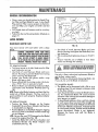
GENERAL
RI COMMENDAI' ON
BLAC'E
Once a year you should replace the Spark Plug,
Air Filter and check Blade for wear° A new Spark
Plug and Air Filter assures proper air-fuel mixture and helps your engine run better and last
longer.
o You should check all fasteners and be sure they
are tighL
o Follow the Service Recommendation
Schedule on
page
ADAPTER
/"
DETAIL
CRANKSHAFT
&
KEY
ADAPTER
8LADE
_-._e'/BLADE
_/:"___
O
/
WASHt
BOLT
_KSHAFT
21.
LOCKWASHER
CRANKSHAFT
KEYWAY
.//
LC
_
BLADE/BLADE
ADAPTERCARE
FIG. 18
Your lawn
Blade.
mower
will
work
better
with
a sharp
o
CAUTION: DISCONNE(1 SPARI( PLUG WIRE
FROM SPARE PLUGAND PLACEWIRE WHERE
iT CANNOT€O_E IN CONTACT
WITH THESPARE
PLUG DO HOT A1TEhIPTTO ADJUSTHEIGHT
OF CUT UNLESS
THE LAWN h_lOWiEIS SITTING
UPRIGHT. PERSONALINJURY _AY RESULT.
,,,llllll
......
Use block
of wood
between
Blade
and Lawn
Mower Housing and tighten the Blade Bolt, turning clockwise..
o The recommended
tightening torque is 35-40 ft_
Ibs_
o Torque wrenches are available
stores and through the catalog.
at most Sears
hi, i, i
TO REMOVE BLADE:
o Turn lawn mower' on its side Make sure Air Filter
and Carburetor
are up
,_ Use block of wood between
Blade
and
I
Lawn
Mower
Housing to prevent Blade from turning
when removing the Blade Boll
o Protect your hands with gloves and/or
wrap
Blade with heavy cloth_
Remove Blade Bolt by turning counter-clockwise
Use a 9/t6"
box or opemend wrench_
o Remove Blade and attaching
hardware
(Bolt,
Lockwasher
and Hardened
Washer)
(See Fig
Use only a Sears authorized
replacement
Btade to
get the best cutting results.
NOTE: We do not recommend sharpening Blade - but
if you do, be sure the Blade is balance&
TO SHARPEN BLADE:
o The Blade can be sharpened with a file or on a
grinding wheel_ Do not attempt to sharpen while
on the lawn mower_
o Care should be taken to keep the Blade balanced. An unbalanced Blade will cause excessive
vibration when running and eventual damage to
lawn mower or engine_
o To check Blade balance, drive a nail into a beam
or wall_ Leave about one inch of the straight nail
exposed. Place center' hole of Blade over the head
of the nail. If Blade is balanced, it should remain
in a horizontal position_ If either end of the Blade
moves downward,
Blade is not balanced.
Sharpen the heavy end until the Blade
balanced.
NOTI_: Remove the Blade Adapter and check the Key
inside hub of Blade Adapter_ The Key must be in
good condition to work properly.
Replace Adapter
if damaged_
TO REPLACE
BLADE:
o
Position
the Blade
Adapter
on the Engine
Crankshafl_ Be sure Key in Adapter and Keyway
in Crankshaft
are aligned.
o Position Blade on to the Blade Adapter aligning
the two (2) holes in the Blade with the raised lugs
on the Adapter°
!'_0TE: Be sure the word TOP (stamped on the Blade)
,s toward the engine (See Fig_ 18)0
o Install the Blade Bolt with the Lockwasher
and
Hardened
Crankshaft
Washer
into Blade
(See Fig° 18).
Adapter
AND MAY MAKE THE ENGINE HARD TO START. I
....................
and
14
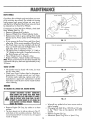
DRIVEWHEELS
DUST
COVER
Check Rear Drive Wheels each time before you mow
to be sure they move freely.The
wheels not turning
freely means trash, grass cuttings, etc. may be inside the Drive WheeJ and Dust Cover area and must
be cleaned out to free Drive Wheels.
If necessary to clean the Drive Wheels, check both
Rear Wheels (See Fig. 19).
, Remove Hubcaps and Locknuts.
o Remove Wheels from Wheel Adjuster Axles_
o Remove any trash or grass cuttings from inside
the Dust Cover, Pinion andlor Drive Wheel Gear
Teeth.
°
o
FIG. 19
If you remove the Drive Pinion and Drive Pawl,
refer to fig. 20 for correct assembly of Drive Pawt.
The Pinion Gear must be installed with the Left
TOP OF MOWER
Gear on the left side and the Right Gear on the
right side, from an operator's
view.
o The Pinion Gear is stamped with an "L" (Left) or
"R" (Right) on the inside. If installed incorrectly,
the Drive System will not work.
o Place Wheels back on Adjuster
Axles
o Replace Washers, Hairpin Cotters and Hubcaps.
NOTE: Pinions and Drive Pawls shoutd be deaned and
lubricated with spray lubricant
25 hours.
approximately
FRONT ,OF MOWER
...........
DRIVE
every
[?_,",
E PAV'/L
SHAF
GRASSCATCHER
o
o
FIG. 20
The Catcher may be hosed with water, but must
be dry when used.
Check your Grass Catcher often for damage or
deterioration..
Through normal use it will wear..
If Catcher needs replacing,
replace only with a
manufacturer
approved
replacement
Catcher
from Sears. Give the lawn mower model number
when ordering.
ENGfl E
TO CHANGEOIL (WARt_ OIL DRAINSBETTER)
CAUTION: DISCONI_ECTBATTERY CONNECTOR
,,%
_J_
FROM ENGINE AND SPARE PLUG WIRE FROM
SPARKPLUGAND PLACEWIREWHEREIT CANNOT
COME IN CONTACTWITH SPARKezuo _0 NOT
ATTEMPTTO ADJUSTHEIGHT OF CUTUNLESSTHE
LAWN MOWER IS SITTING UPRIGHT PERSONAL
INJURY MAY RESULT
...........
i
............................
Remove
surface.
°
Tip lawn mower on its side as shown in Fig 21
and drain oil into suitable container° Rock lawn
Cap;
o Wipe off any spilled oi! on lawn mower and on
side of engine°
o Fill enginewith
SAE 30 or 10W 30 oil. Fill only
to the "FULL"
line on the dipstick.
DO NOT
overfill
IH i _1.
O
Engine Oil
FIG. 21
lay aside
on a clean
o
mower back and forth to remove any oil trapped
inside of engine
15
Replace Engine Oil Cap.
Reconnect Spark Pksg Wire
to Spark-Plug
T
AIR RLTEA
AIR CLEANER
Your engine will not run properly
and may be
damaged by using a dirty Air' Filter', Replace the Air
Filter every year', more often if you mow in very dusty, dirty conditions.
Do not wash Air Filter.
TO CHANGE
COVER LATCH
o
o
o
o
o
o
_PLASTIC
"_
....
AIR FILTER
o Loosen and remove the two (2) Plastic Cap Nuts
on top of Air Cleaner Cover (See Fig, 22),
o Lift up and rotate Cover to unhook Latch on the
front end of Cover.
o
COVER
_
]
HOUS,
_:=_'_
_
_
..,,/C__._.
/
ENGINE
PL
T
FiL"TER ELEMENT
#, A_R
_
I::_:,
-
"""4
\
Y_
Loosen and remove the Wing Nut and Plate
holding Filter" in place (See Fig, 22),
Lift up on the Air Filter Element and remove.
Clean off the face of the Air Cleaner Seal on top
of Carburetor.
CAP
""CARBURETOR
FIG. 22
(LEAN N
When cleaning be careful to keep trash and dirt
from dropping
into Carburetor,
Put new Filter' in place,
Put the Plate and Wing Nut back in place°
Put the Air Filter Cover back, be sure to hook the
front end into the Engine Blower Housing°
Put the two (2) Cap Nuts back and tighten.
We recommend that you clean the underside
lawn mower after each use.
of your'
CAUTION: DISCONHECTBATTERYCONNECTOR
FROM ENGINE AND SPAREPLUG WIRE FROf_
SPARE PLUG AND PLACE WIRE WHERE IT
CANNOT CO_E IN CONTACT WITH SPARE
PLUG, DO NOT ATTEI_tPTTO ADJUSTHEIGHT
OF CUTUNLESSTHE LAWN MOWER IS SITTING
UPRIGHT. PERSONALINJURY MAY RESULT.
SPARKPLUG
Change your' Spark Plug each year to make your
engine start easier and run better. Set Spark Pl_g
gap at ,030 inch_
o Turn lawn mower on its side with Carburetor up.
Clean the underside of your lawn mower' by
scraping to remove build-up of grass and trash_
o Clean your lawn mower and engine often to keep
trash from accumulating around engine_ A clogged engine runs hotter and shortens engine life.
o We DO NOT recommend using a garden hose
to clean lawn mower' unless the Electrical System,
Muffler, Air' Filter, and Carburetor' are covered
to keep water' out. Water in engine can result in
shortening engine life_
16
TO REIVIOVE/REPLACE
DRIVEBELT
CAUTIOH: DISCOHNECTBATI'ERVCOHHECTOR
FROM ENGIEIEAND SPAREPLUG WIRE FROM
SPAREPLUG. PLACEWIRE WHEREIT CANNOT
COMEIH CONTACTWITH SPAREPLUG. DO NOT
ATTEMPTTO ADJUSTHEIGHTOF CUTUNLESS
THE
LAWH ._ftOWERtS SILTINGUPRIGHT. PERSONAL
........
!NJURY MAY RESULT....................
Remove
o
Set lawn mower in number six (6) height of cut.
DO NOT change height setting unless lawn
mower is on its Wheels in normal operating
position.
Turn lawn mower on its side with Carburetor
up_
Locate the Belt Tension Spring and Retaining Pin
on the Back Plate of lawn mower.
from
lawn
PLATE
W_RE
WIRE
..........
o
o
o
Grass Catcher
_ACK
mower.
RETAINING
PIN
FIG. 23
i LOCKNOT
Using a piece of wire, pull the end of Tension
Spring through the hole and remove Retaining Pin
(See Fig. 23)_
Remove the HiWac
Baffle,
See Fig° 24 for
fastener locations°
/
i
I
I
L__B_-"_HI.VAC
BAFFLE
BELT
ENGINE
./"
.__
__-T----_.?_
CRANKSHAFT_.
,_.
,_,_: _ /S'_}/
_
CABLE
\
"_--#_
":_
]CLAMP
_"_
I'--
T
_k _
PO LE " LJ
Remove Cable Clamp and slip Cable Ends out of
Mounting
Slots (See Fig. 24A).
o Tilt Driven Pulley forward until it is resting against
Torque Bracket (See Fig. 24A). Remove Locknut
on top of Driven Pulley. This will allow you to
remove the Belt Keeper and Belt.
o Loosen Bolt holding Belt Snubber (See Fig° 24A),
and slip Belt off of Engine Pulley and over Blade.
To instatt new Belt, slip Belt over Blade and into
Engine Pulley. Readjust Belt Snubber and tighten
Bolt (See Fig° 25 on page 18).
• Place Belt on Driven Pulley and reinstall
Belt
Keeper, Spacer, Spring and Locknut as shown in
Fig. 24A. (Do Not tighten Locknut at this time).
,q
o
"'----t_.,_-_
_
.....
LARGE
,_,-.---1
DPdVEN
4-20
PULLEY
SCREW
FIG. 24
ENGINE
BELT
o With Driven Pulley resting against the Torc_ue
Bracket, rotate the Belt Keeper until right edge
of Keeper is approximately
1/16" from the Torque Bracket (See FiB 25A on page 18) and
tighten Locknut.
o Slip Cable Ends back into Mounting
Slots and
reinstall Cable Clamp_
o Using a piece of wire, pull the Tension Spring
through the hole in the Back Plate and reinstall
the Retaining
Pin (See Fig. 25B on page !8).
DO NOT over stretch Spring as damage to the
Spring may result.
o Reinstall Hi-Vac Baffle_
!
MOUNTING
SNUBBER-
_""
o
BOLT
I:'
BELT
SPRING
KEEPER
\"
_ LOCKNUT-._-
_
TORQUE
DRIVEN
_ BRACKET
PULl
FIG. 24A
17
:
CLAMP
CABLE
S
J
T
TO ADJUST DRIVE CONTROL
•
To check for proper ad ustment of Drive Control,
slowly pull up on the Drive Bar while pulling lawn
mower backwards until Rear Wheels stop turning
o When Rear Wheels stop turning, hold the Drive
Bar and check the dimension as shown in fig 26.
o The Drive Control is properly
adjusted when the
measurement
over the Handle and Drive Bar is
BELT
approximately
3 1/2"
(See Fig 26)_ If the
measurement
is tess than 3 1/2" adjust Drive
Control Cable
APPROx
SNUBBET"_'_"
!:32
_, The Drive Control Adjuster is the one closest to
operator_
o To make the Drive Control adjustment,
hold the
upper hexagon
fitting and turn the Adjusting
Sleeve clockwise, from operator position (See Fig_
27).
o If after several adjustments no further adjustment
is left, the Drive Wheel must be replaced.
N0/E: Through normal use the Drive Wheel will wear.
• If you have problems making the described adjustments, contact your nearest Sears Service
Center.
TORQUE
SPEEDCONTROLRANGE
BELT
FIG 25
APPROX
1,1_6
BEL"
The Speed Control Range is properly
set at the
factory and should not require additional
adjustmenL If you feel speed adjustment is incorrect or
Speed Control does not operate properly contact
your nearest Sears Service Center._
KEEPER
FIG 25A
CARBURETOR
Your Carburetor
has a non-adjustable
Fixed main jet
for mixture control
If your engine does not operate
properly due to suspected Carburetor problems, take
your fawn mower to an authorized
Sears Service
Center for repair and adjustment°
DRP
PULLEY
FIG. 25B
18
MOUNTING
BOLT
ENGINE
Your engine speed has been factory set° Do not attempt to increase engine speed or it may result in personal injury_ If you believe that the engine is running too fast or too slow, take your lawn mower to
an authorized Sears Service Center for repair and
adiustmenL
UPPER
HANDLE
/
"_"
/
DR_VE
BAR
ENGINE
CONTROL
BAR
REARDEFLECTOR
The Rear Deflector, attached between the Rear
Wheels of ycourlawn mower, is provided to minimize
the possibility that objects will be thrown out the rear
of the lawn mower into the operator's mowing
position.
tf the Rear Deflector becomes damaged, it should
be replaced.
FIG. 26
TO ADJUSTHANDLE
o
Grass bag should be removed temporarily
for
easier adjustment
of Handle_
o The Handle on your lawn mower has three (3)
heights - adjust to the height that suits you.
To adjust the Handle, push in on the Adjusting
Levers to dear the Pins (See Fig 28)_
o Raise or lower Handle and position the Adjusting
Levers on to the Pins.
o Be sure that Handle Bracket Pin is in the same
Lever Hole on both sides of the lawn mower.
•1_
,jUPPERFITTING
HEXAGON
i__
)
o ,vECONTROL
ADJUSTING_"_
SLEEVE
DRIVE
_
i
..--UPPER
HEXAGON
FIG. 27
LOWER
HANDLE
HANDLE
BRACKET
PiN
ADJUSTING
LEVER
I
FIG. 28
19
FITTING
Your lawn mower and engine should
for off-season
storage as follows:
be prepared
LAWit iVlOWER
o Clean underside of Lawn Mower Housing. (See
"Cleaning"
in maintenance
section of manual_)
o Inspect and replace/sharpen
Blade, if required
(See
"Blade/Blade
Adapter
Care"
in
maintenance
section of manual)_
o Hose Grass Catcher off with water and let dry
before storing.
o Lubricate as shown in Service Recommendation
chart on page
UPPER
HAND
DRIVE
CONTROL
LOWER
CONTROL
BAR
STORAGE
HAND1
o
POSITION
21 of manual_
ADJUSTING
HANDLE
o
BAR
You can stand your Lawn Mower Handle up for
storage as shown in Fig. 29.
To stand your Handle up for storage, push in on
the Adjusting Levers until the Levers clear the Pins
then raise Handle until it locks in an upright vertical position (See Figs. 29 & 30),
LEVER
FIG. 29
"_,f.LOWER
HANDLE
\\
HANDLE
PiN
EHGIHE
o
Change oil (See "To Change Oil" in maintenance
section of manual).
_, Drain fuel and run engine until fuel system is
emptyr.
tMPORTAHT:IT IS IMPORTANT
TO PREVENT
GUM DEPOSITS FROM FORMING
IN ESSENTIAL FUEL SYSTEM PARTS
SUCH AS THE CARBURETOR,
FUEL
FILTER, FUEL HOSE, OR TANK DURING
STORAGE.
ALSO,
EXPERIENCE INDICATES
THAT ALCOHOL
BLENDED
HOL OR
ADJUSTING
LEVER
FIG. 30
FUELS (CALLED GASO_
USING
ETHANOL
OR
OTHER
METHANOL)
CAN ATTRACT MOISTURE WHICH
LEADS TO SEPARA..
TION AND FORMATION
OF ACIDS
DURING
STORAGE
ACIDIC
GAS
CAN DAMAGE
THE FUEL SYSTEM
OF
AN
ENGINE
WHILE
IN
STORAGE.
o
o
',
Do not store gasoline from one season to another.
Replace your gasoline can if your can starts to
rust. Rust and/or dirt in your gasoline can cause
problems.
Do not store your' lawn mower under any plastic
cover. Plastic cannot breathe which allows condensation
to form
mower to rust°
BATTERY
°
o Disconnect the Battery from the Engine Connector and charge Battery for 48 hours.
2O
and
can
cause
your
lawn
When setting up your' Handle from the storage
position, the Lower Handle will require manual.
ly locking into the mowing position.
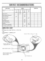
SERVICE
RECORD
Fill in dates
as you
comp}ete
SERVICE
DATES
SCHEDULE
regular
service
First
2
Hours
Every
]0
Every
25
Hours
Hours
Every
Use
Blade Checked
Blade Replaced
(Sharpened)
Engine Oil Change
Engine Oil Check
Air Cleaner
Spark
Plug Replaced
Lubricate
Lawn Mower
Cleaning
Grass Catcher (if applicable)
Drive Pinions and Drive Pawls
LIIRI(II'I'IOII (]'lilt
Q
SAE 30
MOTOR
OIL (10"7',/ 30)
SPRAY
LUBRICANT
BRAKE
HANDLE
PIN
2(,,_..,.,
O
DRIVE
DRIVE
BRACKE"
BRACKET
MOUNTING
REAR
SPRING
DOOR
HINGE
PINIONS
PAWLS
O
(_
Q
ENGINE
211
OIL
©
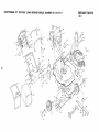
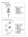
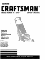
CRAFTSMAN
22"
ROTARY
LAWN
MOWER
MODEL
NUMBER
917.374711
REPAIR PARTS
Rev,
42
/
4
22
4O
fo
34
!
33
/
52
1
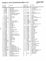
CRAFTSMAN
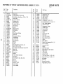
Ref.
No.
Ji
1
2
3
4
5
6
t_
7
8
9
10
11
12
13
14
15
16
17
18
19
20
21
22
23
24
25
26
27
28
29
30
31
32
33
34
35
36
37
38
39
40
41
42
43
44
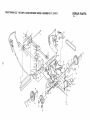
22"
ROTARY
LAWN
MOWER
MODEL
Part
No,
Part
Name
751150
750629
851185
86055
751584
751052
Drive Bar Decal
Upper Handle
Machine Screw
1/4-20 x 2 3/4
Machine Screw
1/4-20 x 2 1/4
Screw 6-20 x 3/8
Drive/Speed
Control Cable Assembly
W/Key Switch
(See page 30)
Spacer
Locknut
1/4-20
Locknut
1/4-20
Spacer
Spacer
Engine Zone Control
Cable
Hex Head Bolt 1/4-20
x 1 1/2
Handle Knob
Belt Snubber
Drive Control
Bar
Control
Bar
Speed Control
Decal
Cable Pull
Instruction
Decal (Engine)
Lower Handle
Handle Bolt 5/16-!8
x 1 3/4
Wire Tie
Wheel Bearing (2 each wheel)
Handle Bracket Adiusting
Assembly
Tube Bolt
Shoulder Bolt
Handle Link (Right)
Handle Link (Left)
Washer
Locknut
5/16-18
Washer
q
751782
751152
STD541425
751625
751385
751665
STD522515
87692
851000
751040
751608
751265
751801
751304
750580
58714
66426
751068
800445
752028
750735
80O444
800443
STD551037
STD541431
800447
800469
751866
750941
STD523108
82678
STD512505
STD5231!7
750721
751302
751872
751152
750718
Spacer
Catcher Frame
Grass Bag Assembly
Hex Head Bolt 5/16-18
x
Hex Head Bolt 5/16-18
x
Hex Head Machine
Screw
Hex Head Bolt 5/16-18
x
Handle Bracket Assembly
Spec Decal
Truss Head Screw 1/4-20
Locknut
1/4-20
Handle Bracket Assembly
7/8
t 3/8
1/4-20
1 3/4
(Right)
x 1/2
(Left)
x 1/2
NUMBER
REPAaR PARTS
917.374711
Rev,
1
Ref,
No.
Part
No.
Part Name
45
48220
46
61528
47
48
851219
850998
49
5O
51
52
53
54
55
56
57
800545
83923
751147
57143
750827
750838
STD560607
751793
851084
58
59
6O
61
62
63
64
65
850263
851074
850973
851514
750694
750700
751116
85463
66
67
68
69
70
71
72
73
74
75
76
7-7
78
79
80
750696
751375
750783
750893
87677
85543
STD502502
751155
62509
751336
751338
751339
751337
751340
750564
Lawn Mower
Housing
(Incl. Ref. #56)
Fiat Head Machine
Screw 1/4-20
x 3/4
Engine Washer
Hex Head Rolling Screw 3/8-t6
xl
t/8
Hubcap
Locknut 3/18-16
Whee! & Tire Assembly
8.0 x 2,0
Washer
Front Torque Assembly
Torque Tube Bushing
Cotter Key
Front Baffle
Hex Head Screw 3/8-24
x 1 3/8
(Grd. 8)
Helical Lockwasher
3/8
Hardened Washer
22" Blade
Blade Adapter
Hi-Vac Tunnel
Battery Cover
Battery Cover Decal
Danger Decal
Rear Door
Door Decal
Spnng (Left)
Hinge Rod
Hi-Pro Key #HP-505
Engine Pulley
Set Screw 1/4-20
x 5/16
Screw 8-16 x 1
Truss Head Screw
1/4-20 x 1
Tunnel Stripe Deca_
"Shift
On The Fly" Decal
Quick 7" Decal
Vac Tac Decal
Housing Decal
Engine - Craftsman
(Source !43.1
Model No. 143.404112
(See pgs. 26-29)
Owner's
Manual
75t 900
CRAFTSMAN
22"
ROTARY
LAWN
MOWER
MODEL NUMBER
917.374711
REPAIR PARTS
Rev. 1
CRAFTSMAN
22"
ROTARY
LAWN
MOWER
MODEL NUMBER
REPAgR PARTS
917.374711
Rev.
Ref.
No.
Part
No,
1
2
3
4
5
6
7
8
9
10
11
12
13
14
15
16
17
18
19
20
21
22
23
24
25
26
27
28
29
30
31
32
33
34
751818
STD522507
86974
750693
STD541431
88664
750898
750253
751888
750892
STD582062
750686
750684
751659
750680
750834
750679
751071
750681
751232
751133
84026
1!142OX
751070
STD572515
750732
STD560607
52160
750688
850018
48219
88028
750699
88349
751580
750829
•
35
36
Part Name
i, ,,,
Ref.
No.
_
Speed Nut
Hex Head Bolt 1/4-20
x 3/4
Hex Washer Head Screw 10-24
Back Plate
Locknut
5/16-18
Deflector
Rod
Rear Deflector
Locknut
5/16-18
Drive Spring
Spacer
Retaining
Ring
Ball Beanng
Pulley
Wave Spring Washer
Stand-Off
Compressron
Spring
Oilite Bearing
Locknut
6-32
Drive Housing
Bearing
Clamp
Hex Thread Screw 10-24 x 1/2
8olt 5/16-18
x 3 1/4
Hex Washer
Head Machine
Screw
Spring Pin
Rocker Arm
Cotter Key
Washer
Friction Wheel Assembly
Dnve Pawl
Drive Shaft Kit (Incl. Ref. #20)
Roll Pin
Pivot Cap
Locknut
1/4-20
Hi-Vat
Shleld
Hi-Vac Handle
x 7/16
6-32
.....37
38
39
4O
41
42
43
44
45
46
47
48
.49
5O
5t
52
53
54
55
56
57
58
59
60
61
62
63
64
65
66
67
68
69
Part
No,
.........
750e98
750993
750998
751155
STD532505
54583
751706
751153
750708
750995
751138
750994
750848
751154
750734
750818
751658
67725
751617
751069
83923
800545
250819
751068
750801
750695
74189
87870
751872
751899
750992
88060
751241
1
Part Name
Single Point Lever
Height Indicator
Slide indicator
Screw 8-16 x 1
Carriage Bolt 1/4-20 x !/4
Hex Tapping
Screw 1/4-20 x 1/2
Rear Torque Assembly
Locknut
5/16-18
Engagement
Linkage
Torsion Spring
Retaining
Ring
Link Indicator
Spacer
Screw 8-16 x 5/8
Dust Cover
Drwe Pinion (RightJ
Wave Spring Washer
Washer
Baffle Stiffner
Wheel & Tire Assembly
8.0 x 2.0
(Incl, Ref, #55}
Locknut
3/18-16
Hubcap
Drive Pinion (Left)
Wheel Bearing (2 each wheel)
Height Tube
Hi-Vac Baffle
Locknut
10-24
]russ Head Screw 1/4-20 x 5/8
Truss Head Scr_:w 1/4-20
x 1/2
Belt Keeper
Dnve Belt
Beanng (Drweshaft)
Flange Bearing - Nylon
(P_FTSMAN4"CYCLEENGJHE
MODEL
.. _"'347
4OO
110
_110B
MODELand SERIAL
NUMBERSHERE
161
130
._" 128
1
\
224
\
t
1201
' 264
!74
266A
Revised
1-5-90
26
143,404,112
(R, FTS AN 4°CYCLE
ENGINE
Re f,,
Part
NO.
No.
35805
26727
33734
34214A
*33735
30200
33886
34695
28277
30589
32651
31335
650548
33578
32600
35816
32323
35544
35545
35546
35541
35542
35543
3554-9
35548
35599
20381
32875
32610A
35616
33553
29914
*35261
35810
MODEL
34645
150
151
153
154
!55
157
158
159
160
16!
31672
31673
35623
650913
35624
650914
35625
*35626
35718
30063
166
178
185
t86
t96
t91
192
193
194
19E
19€
20_
35820
29752
6201
"26756
35635
34358
34968
35248
34966
34965
32309
610973
35035
33205A
202
20_
2O4
20_
203
20£
33802
31342
650549
650777
36364
30200
215
222
23_
24(
24_
355t 1
650451
"35629
650934
650935
35818
650933
*35848
35849
650937
24._
25(
26(
26_
35850
35823
35817
650831
26_
26_
35821
650918
26(
26(
650917
29752
1
Cyiinder Assy (lnc[. Nos_ 2 _f 20)
Pin, Dowe}
Element, Breather
Breather Assy, (IncI Nos ( 8, 9, t2
812A)
Gasket, Breather
Screw, Hex washer hd self-:ap Sems,
10-24 x 9/16
Tube, Breather
Elbow, Breather tube
Washer, Flat
Rod, Governor (Inc! No 14
Lever, Governor
Clamp, Governor lever
Screw, Hex washer hd, 8-3 x 5/16
Spring, Extension
Seal, Oil
Crankshaft
Washer, Thrust
Piston, Pin 8- Ring Assy. (Std.) (lncl.
Nos. 41, 42, _ 43)
Piston,
Pin 8 Ring Assy
.010 over
size) (lncl Nos. 41, 42, _ 4:
Piston,
Pin 8 Ring Assy. (.020 oversize) (Incl. Nos 41, 42, 5" 4_
Piston 8 Pin Assy_ (Std.) (in
No 43)
Piston 8 Pin Assy. (010 oversize)
(IncL Nos. 43)
Piston
8" Pin Assy
(_020 oversize)
(Incl. No. 43)
Ring Set, Piston (Std,)
Ring Set, Piston (O10 overs
)
Ring Set, Piston (.020 overs
)
Ring, Piston pin retaining
Rod Assy; connecting
(Incl No 46)
BoR, Connecting
rod
Valve, Lifter
Camshaft
(Mech.
Corrpression
Release)
Pump Assy,
Oit
Gasket, Mounting
flange
Flange, Mounting (lncL Nos, 72, 73, 75
128
182
22_
8O}
22_
Plug, Oi! drain (lncl. No 731
Gasket, Drain plug (not nece
¥ with
plastic drain plug)
27897
Seal, Oi!
30574
Shaft, Governor
35479
Washer,
Fiat
30591
Gear Assy., Governor (lnci No. 81)
30588A Spool,
Governor
29193
Ring, Retaining
65O488
Screw, Hex hd Seres, I/4-:
x lq/4
611004
Key, Flywheel
611044
Flywheel
650815
Washer,
BeIleville
650816
Nut, Flywheel
3444-3A Solid State Assy.
610118
Cover, Spark Plug
650814
Screw,
Torx Hex washer hd Sems,
10-24 x 1
35619
35620
t35
]
No.
127
30572
"28_33
34961
34970
"35806
35630
35621
35622
130
Part
No.
65O691
65O69O
650912
Ref.
Part Name
23_
23z
i Wire, Ground
Wire, Ground
Gasket, Cylinder head
Head, Cylinder
Valve, Exhaust (Std.) (tncl, No. 151)
Valve, Exhaust (!/32"
over,,
)(tncl.
No. 151}
Valve, Intake (Std) (lncL No 151)
Valve,
Intake (1/32"
overs
) (Incl.
No. 151)
143.404112
Part Name
Washer, Fiat
Washer, Befleville
Screw,
Hex washer hd,
5/16-!8
x
1-1/2
Spark Plug, Resistor (Champion
RN4C or equivalent)
Spring, Valve
Cap, Valve spring keeper
Guide, Push rod
Stud, Rocker arm
Arm, Rocker
Nut, Hex jam
Rod, Push
Gasket, Rocker arm cover
Cover, Rocker arm
Screw, Hex washer hd Seres, !/4-20
x 1/2
Shroud, Assy
Nut Ef Lockwasher,
1/4_28
Screw, Hex hd , 1/4-28 x 7/8
Gasket, Carburetor
Pipe, Intake
Link, Governor spring
Lever. Brake
Bracket, S E Brake (IncI No 1961
Link, Control
Spring, Extension
Ring, Retaining
Terminal Assy
Switch, Assy
Bracket, Assy . Control (tncl Nos 202
thru 2051
Spring, Compression
Spring, Compression
Screw,
Fil hd , 5-40 x 7/!6
Screw, Fil hd, 6-32x2t,32
Link, Throttle
Screw. Hex washer hd self-tap Seres,
t0-24 x 9/16
Knob. Control
Screw, Hex hd Serns. t/4-20 x t
Gasket, Intake pipe
Stud, Air cleaner
Nut, Speciai wing
Bracket. Air cleaner
Nut, Special wing• t _4 - 20
Gasket, Air cleaner
Body, Air cleaner
Screw,
Hex washer
hd
shoulder,
i t0-32 x 43/64
Filter. Air cleaner (paper!
Cover,
Air cleaner
Housing,
Blower
Screw,
Hex washer
hd,
thread, 1/4-20 x 15/32
Grill Starter
Screw.
Torx-T30,
Fiat hd,
1/4-20 x t-7/32
Stud, Manifold
Nut Et Lockwasher.
1/4-28
Powerlok
shoulder•
*indicates Parts Included in
Gasket Set, Ref No, 400
27
C FTSMAN 4°CYCLE
ENGINE
Ref.
No,
Part
No,
270
274
275
276
277
285
287
290
35720
"35865
35851
35852
650729
35000
650884
29774
30t
305
306
307
309
35586
35355
35819
*34265
35499
650562
3t0
3t3
314
35822
34080
650767
315
322A
34990
350t3
CARBURETOR
MODE
[ art Name
Manilold
Ass/,
Exhaust
Gaskt_t, Exha Jst manifold
Mufti ._rAssy
Plate, Lock
Screv/, Hex td., 5/16-18 x 3-3/16
Hub, Starter
Screv _, Hex _ lasher hd, 8-32 x 1/2
Line, Fuel
Claml_. Fuel I ne
Tank, Fuel (]rLct Nos 292 8" 301)
Cap, :uel
Tube, Oil fill
Gask{ t, Fill t[ be
"O" f ling
Screv,.
Hex zvasher hd. shakeproof,
10-32 x 1/2
Dipsti :k, Oil tilt
Spac_,r, Ftywt_eel
Screv,, Hex vtasher hd. sems, taptite,
8-36 ) 5/8
Coil., klternat,)r
Conn_ _ctor
NO.
Ref,
No.
Part
325
325A
330
347
29443
35249
35853
650898
36!
6508-31
370
370A
370B
380
390
395
4OO
35756
35840
35847
632577
590637
34934
35633A
L 143.404112
Part Name
No.
Clip, Wire
Retainer, Wire
Wire, Ground
Screw,
Hex washer hd,, shoulder,
10-32 x 27/32
Powerlok
Screw,
Hex washer hd,,
thread, 1/4-20 x 15/32
Decal, Primer
Decal, Name
Decal, Instruction
Carburetor
(IncL No, 184]
Starter, Rewind
Motor, Electric starter (12 volt)
Gasket Set (Incl, items marked*)
RPM Speed Settings:
(Craftsman
Only)
Low Speed: 2500; High Speed:
3000
*indicates Parts Included in
Gasket Set, Ref No 400
632577
....
'"'""
I
Part
Name
Carburetor
I
!
i
3
1531615I Shaft 8- Laver Assy.
16325041Shutter, Throttle
[
5
1631767
] Spring, Throttle return
i
7
1631184
1 Washer, Flat
I 4 1650506
t Screw,
15
! 6 1631971
i Seat.
19
Throttle
Throttle shutter
Dust
136o451
Primer Assy.
Welch
Inlet Needle, Seat _
(lncl. No. 13)
16310z2t Clip, inlet needle
1632019t Float, Carburetor
1631o24 l Shaft, Float
1631867 / Bow_, Roar
127110 / Gasket, BowFto-body
Nut, Float Bowt
Gasket, Bowl-to-body
Fitting, Fuel inlet
1 11 1631o27
! Plug,
I 13
I _4
I 15
I 16
I 21
i
28
J
Clip Assy_
REWIND
STARTER
NO. 5,.Q0637
Part
I
3
i
l
6
7
I
6
i
t3
1 9
ELECTRIC
STARTER
MOTOR
Name
Starter, Rewind
Pin, Spring (_ncL No. 4)
Washer
t s90615 Retainer
Washer
Spring, Brake
Dog, Starter
I 590616
Spring, Dog
i 590617
I B.9oa_8 Pulley
159o619 Spring, Rewind
Cover, Spring
Housing Assy., Starter
Rope, Starter (Length 98" Et 9/64"
die)
159o452,Handle, Starter
NO, 34934
12
11
!2
.......
i
Part
No.
i 34934
5
1
2
3
4
5
6
7
8
lO
11
59O5OO
34942
12
13
14
15
16
17
18
34947
34946
34951
34952
34948
34953
5906O8
34955
3495O
34954
3345O
-
13
18
15
\
29
Part
Name
Motor, Electric Starter
Ring, Retainer
Retainer, Spring
Spring
Gear
Cap Assyo, Drive end
Nut, Lock
Armature
Housing Assyo
Washer, Thrust
Cap Assy., Commutator end (Ind.
brushes, which cannot be serviced
separately)
Bolt, 10-32 x 3-3/16
Driver, Pinion
Washer, Cup
Ring, Retainer
Washer
Nut, Drive
Washer, Dust
REPAIR
PARTS
22" C_FTSMAfl ROTARYLAWNMOWER
MODELNUMBER917.374711
BATTERY
Ref. Noo
t
2
3
4
Part No.
Part Name
86649
48221
86342
750700
Battery
Battery
Battery
Battery
Pad
Kit
Charger
Cover
DRIVE/SPEED CONTROL
W/KEY SWITCH
\
•
'
"\
1!
Ref. No.
t
Part No.
CABLE
Part Name
i
1
48236
2
109310X
751850
751834
751828
751829
751837
751830
751840
751831
751846
751845
751849
751844
4
5
6
7
8
9
10
11
12
13
14
Drive/Speed Control
Head Kit (Incl_ Ref #27)
Replacement Key
Electric Start Key Switch
Torsion Spring
Drive Actuator
Drive Pulley
Plastite Screw #8 x 7/8
Speed Lever
Washer
Piastite Screw #4 x 5/8
Speed Cable Assembly
Drive Cable Assembly
Wire Harness
Plastite Screw #4_20 x
5/8
T
TS
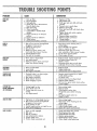
PROBLEM
CAUSE
CORRECTION
DOESNOT
START
1,
2._
3
4_
Dirty air filter_
Out of gasoline
Stale gasoline,
Spark plug wire is disconnected
from the spark plug.
5 Bad spark plug
6, Water in gasoline,
7, Loose blade or broken blade
adapter_
8,_ Engine control bar in released
position.
9_ Engine control bar defective,
10, Weak battery.
11_ Disconnected battery connector.
1. Replace air filter
2. Fill gasoline tank_
3 Drain gas tank and refill with fresh
gasoline.
4, Connect wire to spark plug.,
5r Reptace spark plug
6._ Drain tank and refill with fresh, dean
gasoline.
7 Tighten blade bolt andlor replace
blade adapter
8 Depress engine control bar_
9_ Replace engine control bar
10 Charge battery
1 t. Connect battery to engine.
LOSSOF
POWER
1, Rear of lawn mower housinglblade
dragging in heavy grass,
2, Cutting too much grass.
1rr Raise lawn mower housing one (1)
setting higher,
2 Set in HIGHER CUT position
3, Clean or replace air fi_ter,_
4 Disconnect spark plug wire and
dean underside of lawn mower housing_
5 Cut at slower ground speed,
6, Check engine oil level
, Dirty
air of
filter
Build-up
grass, leaves, and
trash under lawn mower housing
5., Ground speed too fask
6, Too much oii in engine
.............................
POORCUTUNEVEN
1,_ Worn, bent
2 Low engine
3, Build-up of
under lawn
TOOMUCH
VIBRATION
1. Worn or bent blade..
2, Loose blade
3, Bent engine crankshaft.,
.....
.................
_
or loose b_ade
speed,
grass, leaves and trash
mower housing
Replace blade, Tighten blade boff
Set engine speed control on
HIGH or FAST
3, Disconnect spark plug wire & clean
.... underside of lawn mower housing,
t, Replace blade,
2, Tighten blade bolt,
3 Contact Sears Service DepartmenL
.....
,vl
STARTER
ROPE
HARDTO PULL
Flywheel brake is on when engine
control bar is rebased
2_ Bent engine crankshaft,
3, Blade adapter sheared_
4,, Btade dragging in grass,
CATCHERNOT
FILLINGCOMPLETELY
{IF APPLICABLE)
1,, Cutting height too lowo
2_ Lift on blade worn off
3, Catcher bag dirty, poor air
venting,,
4, Low engine speed,
,
i,
1
1_ Depress engine control bar to upper
handle before pulling
on starter rope.
2 Contact Sears Service Department
3 Replace blade adapter.
4., Get over low grass and/or hard surface
to start engine.
.....
,• High
cutting housingfbtade
height too low,
Rear grass
of Iawnor mower
dragging in heavy grass
3, Grass catcher too full,
4, Handle height position not right for you,
, 5o .Drive paw_s hanging._up
1_
2_
3,
4.,
5.,
6_
•
i1,_1
............
1 Raise cutting height
2 Replace blade_
3, Clecmtreplace catcher bag
(If optional grass catcher is being
used)
4,. Set engine speed control on
HtGH or FAST,
HARDTO PUSH
LOSSOF DRIVE
i,,i.......
1
2,
.........
Drive not fulty engaged,
Belt wear,
Belt off of pulieys,
Lost spring tension retainer,
Friction wheel worn,
Friction wheel excessively wet,
31
....
1., Raise cutting height,
2 Raise iawn mower housing one (1)
setting higher_
3. Empty grass catcher
4 Adjust handle height to suit.
5. Clean drive pawls and lubricate.
,
.,
3,
4,,
5,
6,
Check and adjust drive controi,
Checkfreplace drive belt
Checklreinstall drive belk
Replace spring retainer_
Checkfreplace friction wheel,
Allow wheel to dry before use,
i
i,
i,
SEA/R8
5.0 HORSEPOWER
22" REARBAGGER
ELECTRIC
KEYSTART
POWERPROPELLED
ROTARYLAWNMOWER
Each Lawn Mower has its own model number,
engine has its own model number_
Each
The modet number for your lawn mower will be found on
a decal attached to the rear of the lawn mower housing.
The model number for the engine will be found on the
Blower Housing of the engine adjacent to the spark plug
Atl parts listed herein may be ordered through Sears,
Roebuck and Co, Service Centers and most Retail Stores.
WHENORDERING
REPAIRPARTS,ALWAYSGIVETHEFOLLOWING
INFORMATION:
* PRODUCT
- "ROTARYLAWNMOWER"
HOWTO ORDER
REPAIRPARTS
* MODELNUMBER- 917.374711
* ENGINE- CRAFTSMAN
MODELNO. 143.404112
* PARTNUMBER
* PARTDESCRIPTION
Your Sears merchandise has added value when you con.
sider that Sears has service unitsnationwide staffed with
Sears trained technicians., professional
technicians
specifically trained on Sears pi_oducts,having the parts,
tools and the equipment to insure that we meet our pledge
to you, we service what we sell.
751900 Rev. 1 05t07/90
'...................
Printedin U.S.A.
IIII
..............
'llll ...................................................
'1_111'
I I