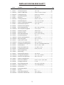
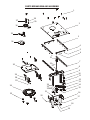
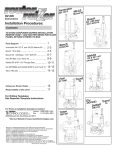
1
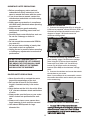
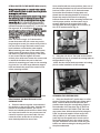
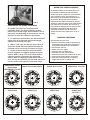
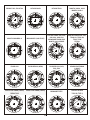
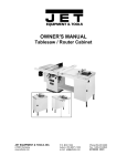
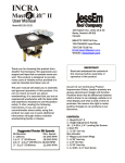
Rout R Lift
User Manual
Model #02001
61 Forest Plain Road
Orillia, Ontario, Canada
L3V 6H1
866-272-7492 Toll Free
705-726-8233 Local Phone
705-327-0295 Fax
Email: [email protected]
Website: www.jessem.com
Thank you for choosing this product from
JessEm Tool Company. We appreciate your
support and hope that our product serves you
well. This product is designed to provide
many years of reliable service provided it is
used as intended and taken care of.
This user manual will assist you in assembly
and general operation of this product. It is
not our intent to teach you about
woodworking. It is assumed that you are an
experienced woodworker with the basic skills
and experience necessary to use this product
safely. If after reading the following
instructions, if you are unsure or
uncomfortable about safely using this
product we urge you to seek additional
information through widely available
woodworking books or classes.
Suggested Router Bit Speeds
Bit Diameter
1” (25mm)
1-1/4” - 2” (30-50mm)
2-1/4” - 2-1/2” (55-65mm)
3” - 3-1/2” (75-90mm)
Max. Speed
24,000 RPM
18,000 RPM
16,000 RPM
12,000 RPM
IMPORTANT!
Read and understand the contents of
this manual before assembly or
operation of this product.
As part of our Continuous Product
Improvement Policy, JessEm products are
always advancing in design and function.
Therefore there may be differences between
what is shown in our catalogs, website or at
retail display and what is sold at time of
purchase. We reserve the right to make
positive changes to our products at our
discretion.
CONTENTS:
1-Rout-R-Lift
1-Height Adjustment Handle
Also includes 1-Insert Ring, 1-Insert Ring
Wrench, 1-1/8” Hex Wrench, 1-5/32” Hex
Wrench, 1-5/64” Hex Wrench, 1-Start Pin,
TOOLS REQUIRED FOR ASSEMBLY:
Screw Driver
7/16” Wrench
IMPORTANT SAFETY PRECAUTIONS
! Before operating any router read and
understand all safety instructions in the
owner’s manual that came with the router.
! If you do not have a manual, contact the
manufacturer and obtain one before using
any power tool.
! Always wear eye protection in compliance
with ANSI safety standards when operating
any power tool.
! Always use proper guards and safety
devices when operating power tools and
machinery.
! Carefully check router bits before each use.
Do not use if damage or defect is
suspected.
! Do not exceed the recommended RPM for
any router bit.
! Do not wear loose clothing or jewelry that
may catch on tools or equipment.
! Unplug the tool or machine when mounting
or making any adjustments to mechanical
performance.
FIG. 1
MOUNTING THE ROUTER
1. Remove the carriage plate (Fig. 1). Using the
5/32 hex key supplied, remove the four 1/4-20 x 1”
flat head cap screws (Item #16 from the parts
diagram on pages 7 & 8) and remove the
aluminum carriage plate.
FIG. 2
2. Remove the master ring (Item# 26 on the
parts drawing - pages 7 & 8) from the carriage
plate. Using the 5/32 hex wrench supplied,
remove the six 1/4-20 x 3/4” flat head cap
screws (Fig. # 2) that secure the clamping
brackets (item #25) to the aluminum carriage
plate.
3. Remove the sub-base and screws that attach
the sub base to your router.
Note: If your sub-base is not removeable, remove
the screws that will be used to attach your router
to the master ring.
DO NOT USE A CORDLESS DRILL TO
RAISE AND LOWER THE LIFT CARRIAGE.
THE AMOUNT OF FRICTION WILL CAUSE
PREMATURE WEAR OF THE THREADS
AND WILL VOID THE WARRANTY
ROUTER SAFETY PRECAUTIONS
! Never force the bit or overload the router
beyond the expectations of the tool.
! Be sure that at least 3/4 of the shank
length is inserted securely in the router
collet.
! Never bottom out the bit in the collet. Allow
1/8” clearance between shank and bottom
of collet.
! Always make sure the fence on your router
table is locked into position before each
use.
! Always rout in two or more passes when
large amounts of stock must be removed.
! Use reduced RPM speeds for large
diameter bits.
FIG. 3
ATTACH THE ROUTER TO THE MASTER RING
1. On page 5 & 6 of the manual there are
drawings showing the mounting hole patterns for
different routers. Locate your router and then
determine which holes to use for mounting your
router to the master ring.
2
ATTACH ROUTER TO THE MASTER RING (Cont’d)
Using a felt tip marker or a pencil make a mark
on the mounting plate for each hole that you will
be using for your router.
With the holes marked on the master ring, place
the mounting plate on the base of your router
and rotate it to line up the tapped holes in your
router (Fig. 3). The countersunk holes and the
engraving on the master ring should be facing
upwards and with the engraved “T” to the top and
the engraved “B” to the bottom. Don’t worry
about handle location at this point as the master
ring can be rotated to any position after the
mounting plate is re-attached to the aluminum
carriage plate.
Note: The master ring is 1/4” thick and the
screws that come with your router may not be
long enough to secure your router safely. If this is
the case source longer flat head screws from a
local hardware or automotive parts supplier.
When fastening your router to the master plate,
lightly secure the screws at first to ensure that
the master ring will locate properly in the center
of your router and then tighten all screws
securely. Also, with some routers the screws used
to attach the sub-base may not be the best
solution for mounting your router to the mounting
ring. Look for 3 or more larger diameter tapped
holes and obtain the proper size screws for the
safest mounting solution.
Once satisfied with the router position, place one of
the clamping brackets into the correct location and
feed one of the 1/4-20 x 3/4” flat head screws
from under the aluminum carriage plate and
thread into the clamping bracket for a loose fit.
Repeat this step for the other five clamping
brackets. Ensure that all the mounting brackets are
in their proper position and the master ring is
securely sitting into the recessed hole in the
carriage plate. Securely tighten all six of the 1/420 x 3/4” bracket screws (Fig. 4).
FIG. 5
2. Using the 1/4-20 x 1” flat head screws (Item#
16, removed in step 1), re-install the carriage plate to
the Rout-R-Lift™ (Fig. 5)
. NOTE: Use the socket head cap screws as locating
pins for easier installation of the carriage.
FIG. 6
FIG. 4
RE-ATTACHING THE MASTER RING TO THE
CARRIAGE PLATE
1. Place the master ring with router attached
into position on the carriage plate. Consider the
position of the handle location, your on/off
switch and variable speed controls to ensure they
are in the best location for easy access once the
router lift is put into your router table. You can
rotate the router at this time to achieve your
most desired position for ease of use.
3
ATTACHING THE LEVELING BARS
1. Place the Rout-R-Lift™ upside down on a flat
surface. Take the four leveling bars (2 long and 2
short - items #3 & #6 from the parts list) and
position them along the corresponding edges of
the underside of the top plate (Fig. 6). Each bar
attaches with two of the 6-32 x 5/16” flat head
cap screws (item #4 from the parts list) using the
5/64” hex wrench supplied. Insert each of the
(10) 1/4-28 x 1/4” set screws (item #5 from
parts list) into the tapped holes at each end of
the leveling bars and one in the center of each
long bar. Thread the set screws in until they just
bottom out without raising the leveling bar from
the plate underneath.
FIG. 8
TAB-LOC PHENOLIC INSERT RINGS
Your Rout-R-Lift™ comes with one insert ring with
a pre-drilled 1-1/2” diameter center hole.
Additional ring sets are available with different
diameter pre-drilled holes and/or no pre-drilled
holes for creating your own custom centerhole
diameters.
1. Place the insert ring into the centerhole of
the Lift’s top plate (Fig. 8).
2. With the insert ring wrench provided, insert
the prongs of the wrench into the corresponding
holes in the insert ring and turn the insert ring
counter clockwise to tighten.
3. Turn the insert wrench clockwise to loosen
and remove the ring. If the insert ring becomes
too tight to loosen with hand pressure, a tap
clockwise on the insert wrench handle with a
block of wood will loosen it.
FIG. 7
LEVELING THE ROUT-R-LIFT™ PLATE
Once the Rout-R-Lift™ is installed into your table,
it needs to be adjusted to sit flush with your table
top surface. If you have a JessEm phenolic table
top the following adjustments can be made
through the pre-drilled access holes from
underneath the table top. If you are using a
custom table top, the leveling adjustments are
made with the lift removed from the table
opening.
1. Check to see that all sets screws are at the
same location within the leveling bars. Back the
screw out and slowly turn each one clockwise
until it bottoms out without lifting the leveling bar
from the plate. When all set screws are in
aproximately the same position, insert the RoutR-Lift™ into your table top. Take note as to where
the main plate is below the surface of your table
top and estimate about how much of an
adjustment is necessary to level the surface.
2. Remove the Rout-R-Lift™ from the table and
with the 1/8” hex key provided adjust the set
screws (Fig. 8) clockwise in the leveling bars to
raise the plate to level.
Be sure to make the adjustments evenly for all
set screws. Only adjust the ends of the long
leveling bars at first. Adjust the center set screws
after the plate has been leveled at the corners.
Do not adjust the set screws too much at one
time, it is better to adjust them slowly in 1/4 to
1/2 turns and test the level after each
adjustment. If you adjust the plate too high
simply turn the set screws counter-clockwise to
lower the plate.
3. After each adjustment, re-install the Rout-RLift™ back into the table top and check that the
plate is flush with the surface. Repeat
adjustments to the set screws if necessary until
the desired leveling is achieved.
USING YOUR ROUT-R-LIFT
CAUTION!
ALWAYS TURN ROUTER OFF AND
DISCONNECT FROM POWER SOURCE
BEFORE MAKING ANY ADJUSTMENT
1. With the router bit installed, place the
adjustment handle (item #36) into the access
port in the main plate.
2. Bring the bit flush to the table top.
3. To raise your router turn the adjustment
handle clockwise. To lower, turn the adjustment
handle counter-clockwise. Keep in mind that one
complete revolution of the adjustment handle
equals 0.050” or 1/20”. Make the desired height
adjustment. When your adjustment is complete,
remove the adjustable handle.
4
Fraction
Decimal
Number of
Revolutions
1/16”
1/8”
1/4”
1/2”
0.062”
0.125”
0.250”
0.500”
1.25 Revolutions
2.5 Revolutions
5 Revolutions
10 Revolutions
JESSEM TOOL LIMITED WARRANTY
FIG. 9
RE-ADJUSTING THE THREAD TENSIONING
All JessEm lifts feature our patented thread
tensioning design. The design holds the position
wherever you set the height. Thread tension is set at
the factory and depending on the amount of use you
may have to reset this adjustment periodically.
1. To adjust the thread tension, turn the Rout-R-Lift™
upside down on a table with the threaded height
adjustment rod facing you (Fig 6).
2. With a 7/16” open end wrench, loosen the 1/4 20 hex nut (Item# 21) located behind the plate the
threaded rod (or lead screw) is mounted on (Fig. 6).
3. Rotate the brass tensioning collar (Item# 23)
counter clockwise so it tightens against the rubber
washer. NOTE: A drop of oil on the rubber washer
eases the rotation of the brass ring against the
washer. When you tighten the brass collar and the
1/4” - 20 hex nut (Item# 21), the set screw must seat
into one of the vertical grooves in the brass collar.
All JessEm products are warranted to be free
from defects in material and workmanship.
JessEm will repair or replace any product which
upon inspection proves to be defective for a
period of (1) year from dated receipt and proof
of purchase. All warranty claims should be
made direct to JessEm Tool Company. Contact
JessEm for a warranty claim return authorization
and instructions to proceed. The consumer is
responsible for shipping costs to return product
to JessEm Tool Company. We will repair or
replace the product at our discretion and
JessEm Tool will return shipment to you at no
charge.
WARRANTY LIMITATIONS
This warranty does not cover:
! Repairs or alterations made or attempted by
anyone other than JessEm Tool Company or
an authorized JessEm service professional.
! Normal wear and tear
! Abuse, misuse or neglect.
! Improper care or maintenance.
! Continued use after partial failure.
! Products that have been modified in any way.
! Products used with improper accessories.
! Premature thread wear due to adjusting
height with electric or cordless drill.
BOSCH 1611 & 1615
FEIN RT1800
PERFORMANCE CLF20&50
BOSCH 1613 (THRU HOLES)
BOSCH 1613 & 1450
BOSCH 1604, 1617 EVS
BOSCH 1619
DEWALT 615
DEWALT 621
DEWALT 625
ELU 3337-9
5
HITACHI M12V
HITACHI TR12
MAKITA 3612b, 3600
MAKITA 3612-C
MAKITA 3621BR & C
MILWAUKEE (OLD STYLE)
PORTER CABLE 100, 536,
690, 691, 692, 693
MILWAUKEE PALM GRIP
MAKITA 1101 SERIES
PORTER CABLE 518, 520,
7518/19, 7538/39,
7529/7536
TRITON
RYOBI 180
RYOBI RE-600 (NEW)
RYOBI RE-600 (OLD)
500, 501
SEARS CRAFTSMAN
(3 HOLE)
SEARS CRAFTSMAN (4 HOLE)
DEWALT 618
SEARS CRAFTSMAN (4 HOLE)
MILWAUKEE 5625
BLACK & DECKER
7614-04 (TYPE 1)
DEWALT 610, ELU 2721
6
PARTS LIST FOR THE ROUT-R-LIFT™
Part #
Description
Size
1......F0001..........Flat Head Cap Screw .............................1/4" x 3/4" ...........................................28
2......P0001-1 ......Aluminum Main Plate ...........................14-3/4" x 11-3/4" x 3/16"......................1
3......E0042-1 ......Leveling Bar (Long)................................3/16 x 1/2" x 13-1/8".............................2
4......F0049 .........Flat Head Cap Screw .............................6-32 x 5/16" ..........................................8
5......F0052 .........Set Screw...............................................1/4-28 x 1/4" .......................................10
6......E0042-2 ......Leveling Bar (Short)...............................3/16" x 1/2" x 6.9 ..................................2
7......S0001 .........Steel Side Supports...............................1/2" x 1/2" x 13-1/4"..............................2
8......E0001 .........Aluminum Shaft Mounting Block ..........1" x 1-1/2" x 10.1"...................................1
9......F0002 .........Socket Head Cap Screw ........................1/4" x 7/8" .............................................4
10 ...M0001 ........Steel Drive Pulley Spindle...................... ................................................................1
11 ...M0006 ........Bronze Flange Bearing .........................3/4" x 7/8" x 3/4" long............................1
12 ...E0001-2......Drive Pulley Mounting Block .................1" x 1-1/2" x 2" .......................................1
13 ...M0011 ........Rubber Timing Belt................................130 XL x 3/8" ..........................................1
14 ...M0005 ........Delrin Drive Pulley .................................20 XL w/0.5" bore ..................................1
15 ...M0009 ........Bronze Sleeve Bearing..........................3/4" x 7/8" x 3/4" long ...........................4
16 ...F0005 .........Flat Head Cap Screw .............................1/4" x 1" .................................................4
17....E0001-3......Aluminum Bearing Mounts ...................1" x 1-1/2" x 4" .......................................2
18 ...S0002-1......Steel Carriage Nut .................................3/4" x 1" x 1-1/2" ...................................1
19 ...F0003 .........Nylon Insert Lock Nut ............................1/2" - 20 .................................................1
20 ...E0002-1......Aluminum Carriage Brackets ................3/8" x 3" x 8-1/2" ....................................1
21 ...F0006 .........Anti Backlash Locking Screw ................1/4"-20 x 1" Half Dog Pt Set Screw ........1
22 ...M0012 ........Rubber Washer .....................................1/2" x 1-1/16" x .093" ............................1
23 ...M0003 ........Brass Anti Backlash Nut .......................1" x .450" x ½"-20 ..................................1
24 ...M0004 ........Threaded Pulley (Delrin)........................20 XL w/1/2"-20 ...................................1
25 ...P0011 .........Master Ring Clamps .............................. ................................................................6
26 ...P0009 .........Master Ring ........................................... ................................................................1
27 ...F0004 .........Socket Head Cap Screw ........................1/4" -20 x 1" ...........................................4
28 ...S0001-2......Carriage Mounting Block ......................1/2" x 1/2" x 3" Steel .............................2
29 ...E0002-2......Aluminum Carriage Gusset ...................3/8" x 2-1/2" x 3" ...................................2
30 ...P0002 .........Aluminum Carriage Plate ..................... ................................................................1
31 ...M0007 ........Bronze Thrust Washer ..........................9/16" x 1-1/4" x 1/16" Thick .................1
32 ...M0042 ........Carriage Lead Screw .............................½”-20......................................................1
33 ...M0008 ........Bronze Flange Bearing..........................1/2" x 5/8" x 3/4" long............................1
34 ...M0017-1 .....Phenolic Insert Ring ..............................1-1/2" Hole Opening ..............................1
35 ...M0016-1.....Inser t Wrench........................................ ................................................................1
36 ...M0018 ........Lift Handle (Arboron) ............................. ................................................................1
37 ...M0015 ........Hex Key..................................................1/4" ........................................................1
38 ...F0007..........Socket Head Cap Screw .......................1/4" x 1-1/4" ..........................................1
39 ...M0041-1.....Phenolic Lif t Handle Knob.....................1/4" Cored Hole .....................................1
7
Qty.
PARTS BREAKDOWN AND ASSEMBLY
1
37
38
39
2
36
35
3
34
4
5
6
31
7
32
30
33
8
9
10
11
29
28
12
27
13
14
15
24
23
22
21
26
16
25
20
17
18
19