1
OWNER'S
MANUAL
MODEL NO.
315.174710
in,,i
CAUTION:
Read Rules for
Safe Operation
and All Instructions Carefully
II III
®
Router
Double
Insulated
"111
IIIIII
IlllIllllll
I Illllllll
I lll
I I 'lllllI
Thank You for Buying
Craftsman Tools
_l
...............
in
,i.
Warranty
Introduction
Operation
Maintenance
,, Repair Parts
®
Designed exclusively for and sold only by
SEARS, ROEBUCK AND CO, Sears Tower, Chicago, IL 60684
612547-8! 5
4-92
PR}NTED IN U S A
..................
, ,
HH
iU,,ll
ii
i]
FULL ONE YEAR WARRANTYON CRAFTSMANROUTER
If thisCraftsmanRouter tailsto givecompletesatisfaction
withinoneyearfromthedate of purchaseRETURNrr TO
THENEARESTSEARSSERVICECENTER/DEPARTMENTTHROUGHOUTTHEUNITEDSTATESandSearewilt
repairit, free of charge.
Ifthlsrouterisusedfor commercial
or rentalpurposes
thiswarrantyappliesforonly90days from thedateofpumhass,,
Thiswarrantygives you specific legalrights,and youmay alsohaveotherrightswhichvary fromstate tostate.
SEARS,ROEBUCKAND CO,
DEPT.73tCR-W
SEARSTOWER
CHICAGO, IL 60684
,,,uu,
,ll,
llllll
,,
,,,,i
i
i
, ,HH
I
INTRODUCTION
DOUBLE INSULATION Is a concept in safety, in electric
power tools, which eliminates the need for the usual three
wire grounded power cord and grounded supply system,
Wherever there is electric current in the tool there are two
complete sets of insulationto protect the user, All exposed
metal parts are isolated from internal metal motor components with protecting insulation.
RULES
IMPORTANT - Servicing of a tool with doubts Insulation
requires extreme care and knowledge of the system and
should be performed only by a qualified service technician.
For service we suggest you return the toot to your nearest
Sears Store for repatr_ Always use original factory replacement parts when servicing.
FOR SAFE OPERATION
READ ALL INSTRUCTIONS
1,
KNOW YOUR POWER TOOL - Read owner's manual carefully.
Learn its applications and
limitations as welt as the specific potential hazards related to this tool,
2o
GUARD AGAINST
ELECTRICAL
SHOCK BY PREVENTING
BODY CONTACT
WITH
GROUNDED SURFACES. For example: Pipes, radiators, ranges, refrigerator enclosures.
3.
4,
KEEP GUARDS IN PLACE and in working order.
KEEP WORK AREA CLEAN. Cluttered areas and benches invite accidents_
5.
AVOID DANGEROUS ENVIRONMENT,
to rain_ Keep work area well lit.
6.
KEEP CHILDREN AND VISITORS AWAY. All visitors should wear safety glasses and be kept a
safe distance from work area. Do not let visitors contact tool or extension cord.
7.
STORE IDLE TOOLS. When not in use tools should be stored in a dry, high or locked-up place out of the reach of children.
8.
DON'T FORCE TOOL.
9.
USE RIGHT TOOL. Don't force small tool or attachment to do the job of a heavy duty to.oL Don't
use tool for purpose not intended - for example - Don't use a circular saw for cutting tree limbs or
logs_
10.
WEAR PROPER APPAREL. No loose clothing or jewelry to get caught in moving parts. Rubber
gloves and non-skid footwear are recommended when working outdoors. Also, wear protective
hair covering to contain tong hair and keep it from being drawn into air vents.
11.
ALWAYS WEAR SAFETY GLASSES,
they are NOT safety glasses.
Don:t use power tool in damp or wet locations or expose
It will do the job better and safer at the rate for which it was designed.
Everyday eyeglasses have only impact_resistant lenses;
Page 2
2
Hll
Ir"ll'l
,,,,_L-
.......
,i I
i
,= L' '1,
_
"
,,r=_r=
.....
_ ....................
-
_
.............
RULES
FOR SAFE OPERATION
12.
PROTECT YOUR LUNGS,
13,
PROTECT YOUR HEARING,
(Continued)
Wear a face or dust mask if operation Is dusty.
Wear hearing protection during extended periods of operation.
1_4o DON'T ABUSE CORD, Never carry tool by cord or yank it to disconnect from receptacle.
cord from heat, oil and sharp edge&
Keep
15.
SECURE WORK.
Use clamps or a vise to hold work. Both hands are needed to operate the tool.
16.
DON'T OVERREACH.
unstable support.
17.
MAINTAIN TOOLS WITH CARE. Keep tools sharp at all times, and clean for best and safest
performance. Follow instructions for lubricating and changing accessories.
18,
DISCONNECT TOOLS. When not in use, before servicing, or when changing
blades, bits, cutters, etc,, all tools should be disconnected from power supply.
19.
REMOVE ADJUSTING KEYS AND WRENCHES.
Form habit of checking to see that keys and
adjusting wrenches are removed from tool before turning it ono
20.
AVOID ACCIDENTAL STARTING.
switch is off when plugging in,
21,
OUTDOOR USE EXTENSION CORDS. When tool is used outdoors, use only extension cords
suitable for use outdoor& Outdoor approved cords are mar_ed with the suffix W-A, for example SJTW-A or SJOW-A.
22.
KEEP CUTTERS
23,
KEEP HANDS AWAY FROM CUTTING AREA. Keep hands away from cutters. Do not reach
underneath work while cutter is rotating, Do not attempt to remove material while cutter is rotating.
24.
NEVER USE IN AN EXPLOSIVE
fumes.
25.
INSPECT TOOL CORDS PERIODICALLY and if damaged, have repaired at your nearest Sears
Repair Center. Stay constantly aware of cord location.
2&
INSPECT EXTENSION
27.
KEEP HANDLES DRY, CLEAN, AND FREE FROM OIL AND GREASE. Always use a clean
cloth when cleaning. Never use brake fluids, gasoline, petroleum-based products or any strong
solvents to clean your tool,
28.
STAY ALERT. Watch what you are doing and use common sense° Do not operate tool when you
are tired, Do not rush.
29.
CHECK DAMAGED PARTS. Before flJrther use of the tool, a guard or other part that is damaged
should be carefulty checked to determine that it will operate properly and perform its intended
function°
Check for alignment of moving parts, binding of moving parts, breakage of parts,
mounting, and any other conditions that may affect its operation, A guard or other part that is
damaged should be properly repaired or replaced by an authorized service center unless indicated elsewhere in this instruction manual
30.
DO NOT USE TOOL IF SWITCH DOES NOT TURN IT ON AND OFF° Have defective switches
replaced by an authorized service center.
31.
Inspect for and remove aft nails from lumber before routing.
32°
DRUGS, ALCOHOL, MEDICATION.
alcohol, or any medication.
3&
When servicing
34.
SAVE THESE INSTRUCTIONS.
Review them frequently and use them to instruct others who may
use this toot. If you loan someone this tool, loan them these instructions also.
Keep proper footing and balance at all times° Do not use on a ladder or
Don't carry plugged-in tools with finger on switch.
CLEAN AND SHARP.
Be sure
Sharp cutters minimize stalling and kickback,
ATMOSPHERE.
CORDS PERIODICALLY
use only Identical
attachments,
Normal sparking of the motor could ignite
and replace if damage&
Do not operate tool while under the influence of drugs,
Craftsman
Page 3
replacement
parts.
OPERATION
Your router is a versatile woodworking toot which will give you years of trouble-free performance It is engineered with the
professional in mind, but its ease of operation allows the amateur to produce work which ts beauttft,,_land precise.
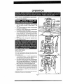
KNOW
YOUR
ROUTER
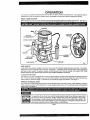
Before attempting to use your router, familiarize yourself with all operating features and safety requirements,
See Figure 1,
WRENCH
"LOCK.ON"
BUTTON
WRENCH
SPINDLE
CLAMPING
HANDLE
HANDLE
DEPTH
STOPRINGS
CHIP SHIELD
SUBBASE
Fig, 1
CHIP SHIELD
A clear plastic chip shieid is installed on the front of your router for protection against ftytng dust and chips. The shtetd is
designed to fit the front opening of the router base. See Figure 1. If necessary to remove chlp shield, squeeze the tabs on
each end and puil outward, To replace, squeeze the tabs at each end, fit into the opening, then ralease_ FOR YOUR
PROTECTION DO NOT USE ROUTER WITHOUT CHIP SHIELD PROPERLY IN PLACE.
"LOCK-ON"
BUTTON
The switch of your router is equipped with a "lock-on" feature which is convenient when operating for extended periods of
time. To lock on, depress the trigger, push in the lock button located on the side of the handle, then while holding the lock
button pushed in, retease the trigger To release the lock, depress the trigger and release it See Figure 1.
WRENCH
STORAGE
AREA
Your router has a wrench storage area located on the top end cap portionof the motor houstng, When installingor removing
cutters remove the wrench from its storage area Proper storage of wrench when not in use w{II help reduce the possibttiity of
tosingwrench. S_a Figure 1,
The operation of any router can reautt In foreign objects being thrown Into your eyes, wht.ch
can result In severe eye damage, Before commencing power tool operation, always wear
safety goggles or safety grasses wtth side shietds and a furl face shield when needed. We
recommend Wide Vision Safety Mask for use over eyeglasses or standard safety glasses wlth
side shields, available at Sears Catalog Order or Retail Stores.
........................
,,,,,i,H,
H
, i
Page 4
OPERATION
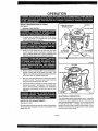
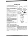
INSTALL1NG/REMOVING
CUTTERS
See Figure2,
t+ UNPLUGYOUR ROUTER+
TURN TO ACTIVATE
SPINDLE LOCK
2.
A Spindle lock is located on the front of the motor
housing
See Figure 1, To activate lock, push spindle
lock tn and slide into lock position,
3.
Place your muter upside down on tab{e, then turn collet
nut with wrench until lock mechanism
interlocks
See
CUTTER
Figure 2. NOTE: Spindle lock is spring loaded and will
snap into position when lock mechanism interlocks,
Fig. 2
TO LOCK
4.
Remove cutters by turning coliet nut counterclockwise
enough to allow cutter to slip easily from colleL
See
Figure2,
The cotlet is machined to precision tolerances
to fit cutters with I/4" diameter shank size+
TO UNLOCK
With your router sti+l upside down on table, insert shank
of cutter into collet L The shank of your cutter shoMd be
close to but not touching bottom of cotter+
6_
Tighten the coltet nut securely by turning clockwise with
the wrench provided+
See Figure 2 Put spindle lock
back in unlock positlon+ Otherwise,
the interlocking
mechanism of the spindle lock will not let you turn your
router
CLAMPING
LEVER
oR.
ELECTRICAL
DEPTHOF
CUT ADJUSTMENTS
See Figures 3 and 4
We recommend thai cuts be made at a depth not exceeding
1/8" and that several passes be made to reach depths of cut
greater than 1/8"
CONNECTION
Your router has a precision built electric motor+ ft should be
connected to a power supply that is 120 volts, 60 Hz, AC
only (normal household
current).
Do not operate this tool
on direct current (DC)
A voltage drop of more than 10
percent will cause a loss of power and overheating
If your
tool does not operate when plugged into an oulIet, doublecheck the power supply rating
Page 5
OPERATION
DEPTH OF CUT ADJUSTMENTS
1,
UNPLUG
(Continued)
YOUR ROUTER.
2
Place your muter on a flat surface, unlock clamping
tever, and adjust until cutter is inside subbaso. See
Figure 3
3 Turn the depth adjusting ring until tip of cutter touches
flat surface, See Figure 4,
4 Position your router so that the cutter can extend below
the subbase for desired depth setting,
5 Turn the depth adjusting ring to obtain the desired depth
ot cuL The distance the cutter moves Can be read on
the depth adjusting ring. Use reference point on motor
housing to measure depth of cut° Each mark on the
depth adjusting ring indicates 1/64 inchchange in depth
setting.
6. Lock clamping lover, securing depth adjusting ring to
motor housing end base,
DEPTH
STOP
BASE
cu'n'ER
RINGS
See Figures 5 and 6
Your router is equipped with depth stop rings that will allow
you to set positive stops for operating your router at two
desired depths of cut
1
2.
3
Release depth stop rings. To release: grasp depth stop
ring tabs with your thumb and index finger, then twisl
them apart as shown by the arrows in figure 5.
Using depth adiusling ring, sot cutter at lowest desired
depth of cut, Lock clamping lever. Position bottom depth
stop ring against depth adjusting ring. Hold depth stop
ring against depth adjusting ring and lock. See Figure 6.
Note: Depth stop ring ends snap together to lock
Unlock clamping lever and move depth adjusting ring to
set culler at second desired depth of cut Lock damping
fever Posilion top depth slop ring against depth adjusting
ring Hold deplh slop ring against depth adjusling ring
end lock See Figure 6 Note: Oeplh slop ring ends snap
together Io lock
Depth stop rings witl now provide a positive stop allowing you
to operate your rouler at two cutter depths
Page 6
-_:_
............
_
T''"'"I"'
. '
'11111
I'll
I
I'
/'.,
'1'11'........
L'""'
Z_I"L_ ..__ .........
OPERATION
RqUTING
_or case of operation and maintaining proper control, your
touter has two handles, one on each side ofthe router baser
When using your router hold it firmly with both hands as
shown in figumm7. Turn router on and letmotor build toits full
speed, then gradually feed cutter into workplece. Remain
alert and watch what you are doing. DO NOT operate muter
When fatigued,
PROPER
FEEDING
The right feed is neither too fast nor too slow. It ts the rate at
which the bit is being advanced firmly and surely to produce
a continuousspiral of uniform chips m without hogging into
the wood to make large individualchipsor,on the other hand,
to create only sawdusL If you are making a smail diameter,
shallow groove in soft, dry wood, the proper feed may be
about as fast as you can travel your router along your guide
line. On the other hand, if the bit is a large one, the cut ts deep
or the wood ishard to cut,the proper feed may be a very slow
oneoThen, again, a cross-graincut may require a slowerpace
than an identicalwith grain cut in the same workpisCeo
There Is no fixed rule. You will team by experience°., by
listening to the router motor and by feeling the progress of
cach cut. If at all possible, always test a outon a scrap piece
of the workpiece wood, beforehand.
RATE
OF FEED
IMPORTANT:The whole "secret"of professionalroutingand
edge shaping lies in making a careful set-up for the cut to be
made and In sclcctlng the proper rate of feed.
FORCE
Fig. 7
,i,,i...................
=[jii
FEEDING
Clean, smooth routingand edge shaping can be done only
when the bit is revolving at a relatively high speed end is
takingvery small bites to producetiny,cleanly severed chips.
If your muter is forced to move forward too fast, the RPM of
the bit becomes slower than normal in relation to itsforward
movement.. As a result, the bit must take bigger bites as it
revoiveso "Bigger bites" mean bigger chips, and a roughcr
finish. Biggcr chips also require more powcr, which could
result in the router motor becoming overloaded.
Under extreme force-feeding conditions the relative RPM of
the bit can become so slow-._nd the bites it has to take so
large--that chips will be padiatly knocked off (ratherthan fully
cutoff), with resultin_ splintering and gouging of the workplace.
Sea Figure 8.
Your Craftsman Router is an extremely high-speed tool
(25,000 RPM no-load speed), and will make clean, smooth
cuts if allowed to run freely Without the ovedoad of e forced
(too fast) feed. Three things that cause =forcefeeding" are blt
size, depth-of-cut, and workpiece characteristics° The larger
the bit orthe deeperthe cut, the more slowly the reutershould
be moved forward. If the wood is very hard, knotty, gummy or
damp, the operation must be slowed stilI more.
J
TOO SLOW
Fig, 8
TOO SLOW FEEDING
it is also possibleto spoil a cut by movingthe router forward
too slowly° When it is advanced into the work too slowly, a
revolving bit does not dig into new wood fast enough to take
a bite; instead, itsimplyscrapesaway sawdust-_ikepadicles.
Scraping produces heel which can glaze, bum, or mar the
cut-- in extreme cases, can even overheat the bit so as to
destroy its hardness.
in addition, it is more difficult to control a router when the bit
is scraping instead of cutting With practically no load on the
motor the bit will be revolving at close to top RPM, and wilt
have a much greater than normal tendency to bounce off the
You can always detect "force feeding" by the sound of the
sides of the cut (especially, if the wood has a pronounced
motor. Its high-pitched whine will sound Iowerand strongeras
grain with hard and soft areas) As a result, the cut produced
it loses speed. Also, the strain of holding the tool will be
may have rippled, instead of straight sides See Figure 8
noticeably increased
Page 7
........................................
•.
'
I[I
[
i'
OPERATION
TOO SLOW
FEEDING
(Continued)
"Too.stow feeding" can also cause your routerto take off in a
wrong direction from the intended line of cut, Always grasp
and hold your router firmly with both hands when rout e
Ing.
DEPTH
OF_UT
14--- WIDTH OF CUT
You can detect "too-slow feeding" by the runawaytoo-highly
pitched sound of the motor; or by feeling the "wiggle" of the bit
in the cut
_"
DEPTH OF CUT
,,
,,,
FfO,9
i
,H
i
,,,
i
,
2ND. PASS
As previously mentioned, the depth of cut is important because it affects the rate of feed which, in turn, affects the
1ST, PASS
I,.1_1 1ST. PASS
quality of a cut (and, atso, the possibility of damage to your
router motor and bit) A deep cut requires a slower feed than
a shallow one, and a too deep cut will cause you to slow the
feed so much thai the bit is no longer cutting, it is scraping,
instead.
--_""---""-_'_'_
Making a deep cut is never advisable. The smaller bits-especia}[y those only !/16 inch in diameter --are easily
broken off when subjected to too much side thrust A large
enough bit may not be broken off, but if the cut is too deep a
Fig. 10
GU,DE
OUTS,DE
,,,H,
R_OTATIO._
N ('_,_
rough cut will result-- and it may be very difficult to guide and
control the bit as desired For these reasons, we recommend
that you do not exceed 1/8 inch depth of cut in a single pass,
regardless of the bif size or the softness or condition of the
workptece_ See Figure 9
GUIDE"
To make deeper cuts it is therefore necessary to make as
many successive
passes as required, lowering the bit 1/8
inch for each new pass In order to save time, do all the cutting
necessary at one depth setting, before lowering the bit forthe
next pass This wtllatso assure a uniform depth when the final
pass _scompleted.
See Figure 10.
j
......
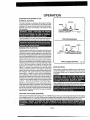
ROTATION
DIRECTION OF FEED AND THRUST
THRUST
The routermotor and bff revolve in a clockwisedirection. This
gives the tool a slfght tendency to twist (tn your hands) in a
counterclockwise direction, especially when the motor revs
up (as at starting).
FEED
GUIDE INSIDE
Fig, 11
,
Because of the extremely high speed of bit rotation during a
"proper feeding" operation, there is very little kickback to
contend with under normal conditions. However, should the
bit strike a knot, hard grain, foreign object, etc. that would
affect the normal progress of the cuttingaction, there will be
a slight kickback---sufficient to spoil the trueness of your cut
if you are not prepared. Such a kickback is always in the
direction opposite to the direction of bit rotation.
,,
i
i i
ROUTING
Whenever you are routing a groove, your travelshould be In
a direction that places whatever guide you are using at the
right-hand side. In short, when the guide is positioned as
shown in the first part of Figure 11, tool travel should be _eft
to right and counterclockwise around curves. When the guide
is positionedas shown in the second part of Figure 11 tool
travel should be right to left and clockwise around curves. If
there is a choice, the first set-up is generally the easiest to
use In eithercase, the sideways thrust you use is against the
guide.
TO guard against such a kickback, plan your set-up and
direction of feed so that you will always be thrusting the tool-tohold it against whatever you are using to guide the cut--in
the same direction that the teadingedge of the bit is moving
In shod, the thrust should be in a direction that keeps the
sharp edges of the bit continuously biting straight into new
(uncut) wood.
Page 8
H'IIH_
_L_
-.---.1 ....................
__
=_._.__H
'u
.--
lUll'fill
I
::_::
........................
:
m:
=.
HI
OPERATION
STARTING
AND ENDING A CUT
INTERNAL
ROUTING
Tilt router and place on workpiece, letting edge of subbase
contact workpiece first Be careful not to let router bit contact
workpieceo Turn router on and let motor buffd to its full speed.
Gradually feed cutter into workpiece until subbase is level
with workpiece.
__PILOT
Upon completion of cut, tum motor off and let it come to a
complete stop before removing router from work suflace_
TOP EDGE
..,11
i .i
,,.,,
SHAPING
.H
,
i
..... .
_
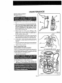
EDGING WITH PILOT BITS
The arbor-type bits with pilotsare excellent for quick, easy,
edge shE/ping Ofany workpiece edge that is either straight or
curved at a curvature as great orgreater thanthe radiusof the
bit to be used. The pilot prevents the bit from making too deep
a cut; and holding the pilot firmly incontact with the workpiece
edge throughout prevents the cut from becoming too shallow.
Whenever the workpiece thickness together with the desired
depthof cut (as adjusted by router depth setting) are such that
onTythe top pad of the edge is to be shaped (reaving at least
a 1t16 Ino thick uncut podion at bottom), the pilot can ride
against the uncut portion, which will serve to guide IL See
Figure t2 However, if the workpiece is too thin or the bit set
too low so that there will be no uncut edge to ride the pilot
against, an extra boa rd toact as agutde must be placed under
the workpieeeA This "guide" board must have exactiy the
same contour-- stra}ght or curved---as the workpiece edge.
If it is positioned so that its edge is flush wffh the workpieee
edge, the bit will make a fun cut (in as faras the bit radius)_ On
the other hand, if the guide is positioned as shown in F{gure
12 (out from the workpiece edge), the bit wit! make less than
a full cut -- which wiil after the shape of the finished edge.
WHOLE
EDGE
SHAPING
Fig, 12
EDGEROUTING
Place router on workptece, making sure the router bit does
not contact workptece Turn router on and let motor build to
its full speed. Begin your cut, graduaBy feeding cutter into
workpteca_
NOTE: Any of the piloted bits can be used withouta pilot for
edge shaping with guides, as preceding The size (diameter)
of the pilot that is used determines the maximum cut width
that can be made with the pilot against the workptece edge
(the small pilot exposes all of the b{t; the large one reduces
this amount by 1/16 inch)_
Upon completion of cut, turn motor off and let it come to a
complete stop before removingrouter from work surface.
ROUTING WITH GUIDE BUSHINGS
When using the Template Guide Bushings Cat. No_9-25082 with your router, you must visuallycenter the bit with the bushing
before beginning your cut. Your router subbase may be adjusted by loosening the screws holding the subbase to your router
Be sure clamping lever is locked before centering bit in bushing, After centering bit with bushing tighten screws firmly°
Page 9
J
I
i,i]
.....
.
MAINTENANCE
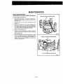
SWITCH REPLACEMENT
See Figures 13 & 14
1, UNPLUG YOUR ROUTER.
C
2,
Remove screws (A) and handle cover (B). See Figure
13.
3,
NOTE THE LOCATION OF THE MOLDED BEND RELIEF (C) ON THE POWER HANDLE CORD, ALSO
NOTE ALL WIRING IN THE HANDLE AND HOW EACH
LEAD IS CONNECTED TO THE SWITCH° Connec*
lions and wiring position must be identical when instafl_
trig new switch, See Figure 13
4
Remove leads from switch (D) by inserting a 1/32"
diameter nail or pin into switch teed receptacle and
putting on lead as shown in figure _4 Remove nail or
pin with a twisting, pulling motion
D
Fig. 13
,, 11
LEAD
5o Make lead connections to new switch. Push each lead
as far as possible into proper switch receptacle. Pull on
leads to check lead connections with lead receptacles.
6.
Locate switch in handle and place leads so they won',t
be pinched or contact screws when handle cover i_;
replaced
7
Make sure molded bend relief (C) is correctly positioned
in switch handle, then replace handle cover and screws
8,
Tighten all screws securely,
DEPTH
ADJUSTING
ADJUSTMENTS
Tension
RING
OR REPLACEMENT
on the depth adjusting ring has been factory set for
properly tightening depth of cut settings, However,
use may require that adjustments or replacement
to depth adjusting ring See Figures 15-1Z
1o
UNPLUG
extended
be made
MOTOR
,HOUSING
YOUR ROUTER,
DEPTH
ADJUSTING I
To make adjustments
2
to depth adjusting
ring=
_ghten
or loosen lop screw in depth adjusting ring,
See Figure 15. Make adjustments with top screw onfy,
DEPRESS
BASE _
Page 10
LIP
Fig, 15
MAINTENANCE
DEPTH ADJUSTING RING
ADJUSTMENTS OR REPLACEMENT (Continued)
=ill
REAR OF DEPTH ADJUSTING RING
To replace depth adjusting ring;
3
Remove depth stop rings, To remove: Depress lip on
depth stop ring and sfide end of depth stop ring over Itp_
See Figure 15.
4,
Remove screw from rear of depth adjusting ring. See
Figure 16_
5.
Remove two screws on front of depth adjusting ring,
Also remove slide nut from pocket inside clamping lever. NOTE = Depth adjusting ring replacement ls the
only time bottom screw should be removed.
6.
Remove depth adjusting ring
7.
Position new depth adjusting ring in place and secure
with the same screws and slide nut used to secure old
_EW
depth adjusting r_ng.
8.
Make all adjustments with top screw (#10-32 x 15/16 =
FiL Hd,) as mentioned previously. Bottom screw (#619 x 1/2" Pan Hd,) should have up to a maximum 'U4"
(.250) clearance, allowing flexibility for top screw adjustments See Figure 17.
Fig. 16
FRONT OF DEPTH
ADJUSTING
RING
1/4" {.250) MAXIMUM CLEARANCE
Fig. 17
Page 11
MAINTENANCE
GENERAL
Only the parts shown on parts list, page 15, are intended to
be repaired or replaced by the customer
All other parts
represent an important part of the double insulation system
and should be serviced only by a qualified Sears service
technician.
Avoid using solvents when eteaning plastic parts.
Most
plastics are suscept+ble to various types of commercial
solvents and may be damaged by their use
cloths to remove dirt, carbon dust, etc
Use clean
PROPER CARE OF CUTTERS
PROPER CAREOFCOLLET
Get faster more accurate culting results by keeping cutters
clean and sharp. Remove atl accumulated pitch and gum from
cutters after each use
From
coflet
coltet
return
A cutter sharpening kit (Cat No 9-66501)
Sears Catalog Order or Retail Stores
is available
from
same as originally
EXTENSION
ground
All of the bearings in this toot are _ubr[cated with a sufficient
amount of high grade lubricant for the life of the unit under
normal operating conditions.
Therefore, no further lubrication is required
CORDS
The use o{ any extens+on cord wit{ cause some _oss of power,
To keep the _oss to a minimum and to prevent toot overheat+
ing, follow the recommended
cord sizes on the chart at the
right When toot is used outdoors, use only extension cords
suitable tor outdoor use and so marked
Extension cords are
available
time to time, it atso becomes necessary to clean your
and coder nut To do so, simply remove col+e! nut from
and clean the dust and chips that have collected Then
collar nut to its original position
LUBRICATION
When sharpening cutters, sharpen only the inside of the
ct._tting edge Never grind the outside diameter Be sure when
sharpening the end of a cutter to grind the c+earance angle the
y
When electric tools are used on fiberglass boats, sports
cars, wallboard,
spackling compounds,
or plaster, it has
been found that they are subject to accelerated
wear and
possible premature
failure, as the fiberglass
chips and
grindings
are highly
abrasive
to bearings,
brushes,
commulator, etc Consequently,
it [s not recommended that
this tool be used for extended work on any fiberglass material,
wa!iboard; ° spack+ing compounds,
or ptaster.
During any
use on fiberglass it is extremely important that the tool is
cleaned frequently by blowing with an air jet
Extension
at Sears Catatog Order or Retail Stores
+
Page
Cord Length
0-25 Feet
25-50 Feet
50-100 Feet
12
Wire Size A.W,.G.
18
16
14
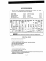
ACCESSORIES
-----
THE FOLLOWING RECOMMENDED
ACCESSORIES
ARE CURRENT
AVAILABLE AT THE TIME THIS MANUAL WAS PRINTED.
(9-2579)
Template
Box Joint Temptate
(9-2580)
Rout-A-Form
MiU Works Molding
(9-25254)
Template
BIs-Kit Plate Jointer Kit
(9-25423)
Sharpening
Multi,Purpose
(9-25179)
Full View Router Base
Dovetail
Template
Router Guide
,,
PANEL
I
tin'rim
I
Bushings
(9°25082)
Pantograph
(9-25183)
Set
(9-2573)
Kit
(9-66501)
(9-25086)
,,,
VEINING
NATIONl
Maker
Guide
AND WERE
BffS
CORE BOX
BIT
STRAIGHT
FACE
BITS
O
2632_"1/4"
;t6326-,1,_"
26330-1/_"
26329-3J16"
V-GROOVE
CHAMFER
26_28-7/32"
26327-I14 =
DOUBLE EHD
45 ° 60•
V-GBQOV_
26333
;_6322_ft2"
"25S78-f/2"
OMBI.,
NATION
HINGE
MORTISING
STRAIGHT,
BEVEL
CUTTER
BIT
CUTTER
BFI_
25313-1/2"
26312-314"
_25524-114"
_25525-5/16"
iRABBETi OGEE j
BIT
i
BIT
BEAD
3/16_
2_305
i
i
263ol.518"
i '25576-3/8"
"2_575-.It_"
ARBOR
I QUARTER,
ROUND
]
25_
BITS
I
I
E3]
FO_
i
"2541
1/4",
VEN_ER
cUTTER
STRAIGHT
"25413
26336
26,319,11_"
26318,I12 _
5/16_
BEVEL
F
The use of attachments
ROMAN Of=
&R _
1
CHAMFER I
BIT
I
25309_114"
2_308-3_B"
2_307.1_"
26310
_25_82
"25827-1t2"
_2_506-314"
COVE I
I
i
LI @
25315-1t_"
26314_
_
O
i
"25504,t14"
I
26303
I
"25,_03,114"
"25586,,3/_"
"255_5,1Z2"
WITH 2
SALL
BEARING, _
|112 & 5ll_'
*2Sag5
7_,,_,o,T,,,,o.,,_' L_J
or accessories not listed above might be hazardous.
HELPFUL
HINTS
,/
Always clamp workplace securely before routing,
,/
A safe operator is one who thinks ahead,
,/
Always wear eye protectfon when routing.
,/
Make set-up adjustments carefully, Then double check. Measure twice and cut once.
,/
Keep cutters ciean and properly sharpened.
,/'
Don't let familiarity make you caretesso
,it
Study all safety rules and do the Job safely.
,/
NEVER place your hands in Jeopardy,
v"
Make certain clamps can't loosen while In usa.
,/
Test difficult set-ups on scrap--Don't waste lumber.
,/
Pian each operation before you begin.
,/
Clean your router frequently..This will provide smoother operation of depth adjusting ring and clamping lever areas.
Shake router or blow with an air Iet to remove sawdust build-up
v'
THINK SAFETY BY THINKING AHEAD.
Page 13
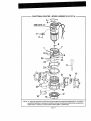
CRAFTSMAN
ROUTER
- MODEL
NUMBER
315,174710
.....
._
SEE NOTE "A"
9
15
21
12
1_
12
5
NOTE: _A" - The assembly shown represents an important part of the Double Insulated System. To avoid the
possibility of alteration or damage to the System, service should be performed by your nearest Sears
Repair Center° Contact your nearest Sears Catalog Order or Retail Store.
Page !4
' " CRAFTSMAN
[
,
,,,
,,
,, ,
ROUTER
,
,,i,
- MODEL NUMBER
,,,,,
, ,,,, ,,,
315,174710
,,,,,,,,,t
.......
i,,,i,,,,,,, i
,
u
The model number will be found on a plateattached to the motor houslng. Always mention the model number
in all correspondence regarding your ROUTER or when ordering repair parts,
SEE BACK
PAGE
FOR PARTS
ORDERING
INSTRUCTIONS
PARTS LIST
Key
No.
Part
Number
Description
Quan,
1
970855-001
2
612866-001
3
970510-001
Cap Screw (#5-40 x 1/4= Soc Hd,) .....................................................
Lock Button
1
t
4
970692-001
Label ............................................. _
1
5
970518-001
Data Plate ......................................................................................................1
6
989985-003
Collet Nut (1/4")................................................................................
:............ 1
7
970504-001
Depth Adjusting Ring ................................................................................ t
8
703774-005
Steel Baft (3/t6) .............................................................................................
6
9
990146-002
" Screw (#10-32 x 15/16" Fil, Hd,) .................................................................1
t0
968700-007
" Screw (#6-19 x 1/2" Pan Hal)
11
989935-006
12
971538-000
13
606066-004
14
623814-004
Switch ......................................................................................................... 1
15
617966-028
" Screw (#8-10 x 1/2" Pan Hal,) ........................................................................
8
t6
970503_003
" Screw (#5-20 x 3/8" Hi-Lo FiL Hd.) ..............................................................
!
......................................................................................
..........................................................
1
...................................................................
Wrench (9/t6") ......................... ,.:,..........................................................
Power Handle Assembly
...............................................................................
" Screw (#10-32 x 3/4" Pan Hdo)
1
1
4
...............................................................
Base ...................................................................................................................
I
17
612191-004
18
998586-001
19
606688-002
Ghtp Shield ..............................................................................................
20
9705t9-091
Logo Plate .................................................................................................. 1
21
970697-000
22
94t401-835
Handle Assembly
Roll Pin...................................................................................................
t
1
23
970505-001
24
970511_001
Stop Ring
Clamping Lever ........................................................................................
2
1
25
9705t5-001
Slide Nut (#t0-32) ..........................................................................
Owner's Manual
1
612547-815
Subbase ..................................................................................................
t
* Screw (#t0-32 x 1/4" Pan Hd,) ..................................................................3
.....................................................................................
...........................................................................................
* Standard
Hardware
Item - May Be Purchased
Page 15
Locally
1
!
CRRFTgMRN °
OWNER'S
MANUAL
Router
Double
Insulated
Now that you have purchased your Router, should a
need ever exist for repair parts or service, simply contact
any Sears Service Center and most Sears, Roebuck and
Co, stores. Be sure to provide all pertinent facts when
you call or visit°
SERVICE
The model number of your Router will be found on a plate
attached to the motor housing.
MODEL NO.
315.174710
WHEN ORDERING REPAIR PARTS, ALWAYS
THE FOLLOWING INFORMATION:
HOW TO ORDER
REPAIR PARTS
GIVE
, PART NUMBER
• PART DESCRIPTION
. MODEL NUMBER
315.!74710
• NAME OF ITEM
Router
All parts listed may be ordered from any Sears Service
Center and most Sears stores.
If the parts you need are not stocked locally, your order
will be electronically transmitted to a Sears Repair Parts
Distribution Center for handling,
SEARS,
ROEBUCK
AND CO,
Sears Tower,
Chicago,
IL 60684