1
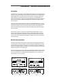
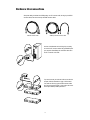
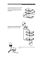
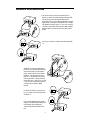
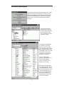
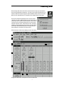
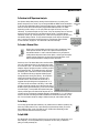
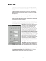
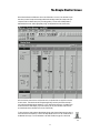
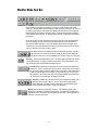
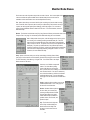
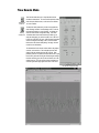
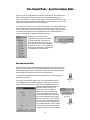
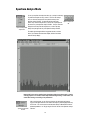
Wireless System Manager for Windows® 95
OWNERS MANUAL
®
Windows and Windows logo are registered trademarks of Microsoft Corp.
Table of Contents
Introduction 1
Hardware Interconnections 1
Software Installation 5
Launching Wireless System Manager 7
Quick Start 8
Monitor Mode 10
The Simple Monitor Screen 11
Monitor Mode Tool Bar 12
Monitor Mode Menus 13
Time Domain Mode 14
Spectrum Analyze Mode 15
Produced by On The Right Wavelength for Samson Technologies Corp.
Copyright 1998, Samson Technologies Corp.
Printed April, 1998
Samson Technologies Corp.
575 Underhill Blvd.
P.O. Box 9031
Syosset, NY 11791-9031
Phone: 1-800-3-SAMSON (1-800-372-6766)
Fax: 516-364-3888
Introduction / Hardware Interconnections
Introduction
Congratulations on your purchase of the Samson Wireless System Manager! This remarkable accessory
package for the Samson Synth Series 6 UHF Wireless System includes Windows 95-compatible software
and all required hardware for complete computer control and remote monitoring of up to eight Samson
UR6D (or UR6DX) dual receivers (for up to sixteen-channel operation). The WSM application also
includes advanced features such as RF spectrum analysis and automated channel planning. WSM even
allows you to record receiving conditions in real time (both RF and AF levels) and to log the results to
disk or print them out.
In these pages, you’ll find full hardware interconnection and software installation instructions, as well as
a guided tour through the various screens, menus and options of the Samson Wireless System Manager.
You’ll also find a warranty card enclosed—don’t forget to fill it out and mail it! This will enable you to
receive online technical support and will allow us to send you updated information about other Samson
products in the future.
SPECIAL NOTE: Should any components in your Samson Wireless System Manager ever require
servicing, a Return Authorization number (RA) is necessary. Without this number, the unit will not be
accepted. Please call Samson at 1-800-372-6766 for a Return Authorization number prior to shipping
your unit. Please retain the original packing material and, if possible, return the unit in its original carton
and packing materials.
Hardware Interconnections
The Wireless System Manager will work with any Pentium computer (including laptop computers) that is
running Windows 95 and has a Sound Blaster 16 sound card installed (note that WSM may not operate
correctly with third-party sound cards). 5 megabytes of hard disk space is required for installation, and a
minimum of 16 megabytes of RAM is recommended. A 21" color monitor or larger is also recommended,
although the program will work on smaller monitors.
There are two hardware interface boxes provided with the Wireless System Manager: the IF6P and IF6R.
As shown in the illustrations below, they are essentially identical, except for the “PC” connection on the
IF6P (on the right-hand side). The IF6R interface box is required only when you need to remote your
receivers 20 feet or more from the computer.
SAMSON
RECEIVE
SAMSON
SEND
WSM
3
2
1
IN
Interface IF6R
3
2
1
IN
OUT
WSM
3
2
Interface IF6P
PC
OUT
IN
3
2
1
IN
OUT
PUSH
PUSH
2
OUT
2
1
1
3
3
IF6P
IF6R
1
Hardware Interconnections
All required cabling is included in the WSM package: one PC connector cable, four long 8-pin mini-DIN
connector cables, and seven short 8-pin mini-DIN connector cables:
WSM PC connector cable
WSM 8 pin mini-DIN connector cables
As shown in the illustration on the left, begin by connecting
one end of the PC connector cable to the joystick/MIDI port of
your computer’s Sound Blaster 16 card and the other end to
the “PC” connection on the IF6P.
If you need to remote your receivers 20 feet or more from the
computer, follow the instructions on page 4 of this manual.
If not, take one of the long 8-pin mini-DIN connector cables
and connect one end to the IF6P “1 Out” and the other end to
the rear panel UR6D (or UR6DX) “Remote In.”
2
Hardware Interconnections
As shown in the illustration on the right, if you are using multiple
UR6D or UR6DX receivers (WSM can control up to eight of
them), use short 8-pin mini-DIN cables to connect the “Remote
Out” of the first receiver to the “Remote In” of the next one,
daisy-chain fashion.
Then connect the “Remote Out” of the last UR6D or UR6DX
receiver to the IF6P “1 In.” If you are only using a single
UR6D or UR6DX, connect its “Remote Out” to the IF6P
“1 In.”
The last step in the process is to set the “1-2-3” switch on the side of the
IF6P to “1.”
3
Hardware Interconnections
If you need to remote your receivers at a distance from the
computer, you need to use the IF6R interface as well as the IF6P.
There are two ways of interconnecting the IF6R and IF6P.
The first option is to use a CAT5 cable (up to 200 meters in length),
plugged into the “2” connection of both interface boxes. As shown
in the illustrations on the left, use the “1 In” and “1 Out” connectors
on the IF6R (not the IF6P) to interface with your UR6D or UR6DX
receivers (as before, up to eight receivers can be daisy-chained
together).
Then set the “1-2-3” switch on the side of both the IF6P and IF6R
to “2.”
Alternatively, as shown in the illustrations on
the right, you can use standard mic cable with
XLR connectors (again, up to 200 meters in
length). Plug the male end of one cable into
the IF6P “In 3” and the female end into the
IF6R “Out 3.” Plug the male end of the other
cable into the IF6R “In 3” and the female end
into the IF6P “Out 3.” Again, use the “1 In” and
“1 Out” connectors on the IF6R (not the IF6P)
to interface with your UR6D or UR6DX
receivers.
For this kind of connection, you’ll need to set
the “1-2-3” switch on the side of both the IF6P
and IF6R to “3.”
If you encounter difficulties with any aspect of
setting up your Wireless System Manager, you
can call Samson Technical Support at
1-800-372-6766) between 9 AM and 5 PM
EST.
4
Software Installation
Before installing your WSM software, you need to
make sure that the external MIDI port on your Sound
Blaster 16 card is enabled. To do so, click on the Start
button and go to Settings -> Control Panel. Once the
Windows Control Panel is open, select the
“Multimedia” option, as shown in the illustration on the
right.
As shown in the illustration on the left, when the
“Multimedia Properties” dialog opens, click on the
“Advanced” tab. Open the “MIDI Devices and
Instruments” folder and select “MIDI for External
MIDI Port.”
Click on “Properties” and the “MIDI For External MIDI Port
Properties” dialog appears, as shown in the illustration on the
right. Click on the “Use MIDI features on this device” button if
it is not already selected and make sure that the Status is
“Driver is enabled and active.” If it is not, WSM will not
operate correctly. Consult your Windows 95 and/or Sound
Blaster 16 user manuals for information on how to solve
conflicts that prevent the driver from being enabled.
5
Software Installation
If all is working correctly, when you click on the “Settings” button, a dialog
similar to the one shown on the left will appear. At this point, you have
enabled the Joystick/MIDI port on your Sound Blaster 16 card and have
verified that the required Creative Labs software driver is installed and
operating correctly. Click OK in all open dialog boxes and close the
Control Panel.
Now you’re ready to insert the
WSM floppy disk! After doing so,
start up the Windows Explorer and
open your floppy drive (usually
drive A). The display will look like
the illustration on the left.
Before installing the WSM application,
you need to first copy the font file
named “Lucon” onto your hard disk.
This file must be placed inside the Fonts
folder in the Windows folder, as shown
in the illustration on the left. From within
Windows Explorer, you can simply
mouse-drag the “Lucon” file from the
floppy drive to the Fonts folder.
Once this is completed, simply
double-click on the “WSM.exe” icon to
begin the automatic installation
procedure. Follow all on-screen
instructions, and you’re done!
NOTE: In case you lose this manual,
we’ve included an electronic copy of it
on the WSM installation disk. This file
(which can be viewed onscreen or printed out) is in Acrobat PDF format. To
open it, you need the Adobe Acrobat
Reader, which is available for free
downloading from the Adobe website
or from many other websites.
6
Launching WSM
Before launching WSM, make sure all receivers are interconnected correctly (as per the instructions
given on the preceding pages) and powered on. Then boot up your computer and double-click on the
“Shortcut to WSM” icon to launch the program. Because WSM uses all driver resources of the Sound
Blaster 16 card’s Joystick/MIDI port, it is not possible to launch multiple instances of the program.
When launched, WSM will automatically load the most recently created
“.WSM” file, if one exists. (.WSM files contain the current channel setup, all
recorded data, and the contents of all Scene Memories). It then scans all
connected receivers to check that all parameters in the receivers exactly
match that of the data in the file. If the data does not match, the program
will display a warning dialog similar to the one shown on the right. Click on
OK to continue; WSM will automatically read in all changed parameters,
always reflecting the current status of connected receivers.
WSM always begins in Monitor mode, displaying the screen shown below:
1
2
3
4
5
8
6
7
See page 10 in this manual for a description of the various numbered areas.
7
Quick Start
To Monitor Conditions In Connected Receivers
Transport Tool Bar icons
From Monitor Mode, click on the Play icon (the far left icon) in the Transport Tool Bar. All RF
and AF Level meters in the Monitor screen are now active and show continuous changes in
RF and AF levels.
To Change Conditions in Connected Receivers
Double-click on any parameter you wish to change, or use the Setup menu Channel option to open the
Channel Setup dialog (see page 10 in this manual for more information). Select the appropriate receiver
tab(s), then the field(s) you wish to change, then click on OK. WSM will instantly send all changed
parameter(s) to your connected receivers.
To Record Data
Click on the Record icon (the far right icon) in the Transport Tool Bar. Changes in all RF and AF levels in
all connected receivers are now being recorded by WSM. To momentarily pause recording, click on the
Pause icon (the second from right icon) in the Transport Tool Bar. To conclude recording, click on the
Stop icon (the second from left icon) in the Transport Tool Bar.
To View Recorded Data
Time Domain
Mode icon
Go to Time Domain Mode, either by selecting it from the Window menu, or by clicking on
the Time Domain icon in the Tool Bar. To determine which parameters you wish to see
graphed out, select “Drawing Condition” from the Settings menu, or click on the Drawing
Condition icon in the Tool Bar. In the resulting dialog, select the appropriate receiver
tab(s), then check the data type(s) you wish to view (RF Level A, RF Level B, RF Level
A+B, and/or AF Level), then click on OK. The selected data for the chosen receiver will
be graphed onscreen. Each parameter is shown in a different color, as described in the
onscreen legend at the upper right-hand corner of the screen.
Drawing
Condition icon
To Save Recorded Data
Return to Monitor Mode, either by selecting it from the Window menu, or by clicking on the
Monitor Mode icon in the Tool Bar. Click on the Save icon in the Tool Bar or, from the File
menu, select the “Save” or “Save As” option (the latter allows you to assign a new filename).
Monitor Mode A standard Windows dialog follows, which allows you to save all recorded data to a file on
icon
disk (the suffix “.WSM” will automatically be appended to all such files).
Save icon
To Load A File
Load icon
From Monitor Mode, click on the Load icon in the Tool Bar or, from the File menu, select the “Load”
option. A standard Windows dialog follows, which allows you to load any “.WSM” file from disk.
To Start A New WSM Session
New icon
From Monitor Mode, click on the New icon in the Tool Bar or, from the File menu, select the “New” option.
Connected receivers will be unaffected, but all data in memory will be cleared.
8
Quick Start
To Perform An RF Spectrum Analysis
Go to Spectrum Analyze Mode, either by selecting it from the Window menu, or by clicking on the
Spectrum
Spectrum Analyze icon in the Tool Bar. If you are using both UR6D and UR6DX receivers simultaneous- Analyze Mode
icon
ly, call up the Group Select dialog either by opening the Setting menu or by clicking on the Group Select
icon in the Tool Bar, then choose the frequency range (standard UR6D frequencies or “X” UR6DX
frequencies) you wish to analyze. You can opt to perform the analysis one time only or to loop it
continuously. To perform the analysis once only, choose “1 Time” from the Analyze menu, or click on the
Analyze Once icon (the left-most icon) in the Spectrum Analyze Tool Bar. To repeat the analysis
Group Select
continuously, choose “Loop” from the Analyze menu, or click on the Loop Analyze icon (the center icon)
icon
in the Spectrum Analyze Tool Bar. To stop a continuous analysis, choose “Stop” from the Analyze
menu, or click on the Stop Analyze icon (the right-most icon) in the Spectrum Analyze Tool Bar.
For more information, see pages 15 - 16 in this manual or refer to the online Help.
Spectrum Analyze
Tool Bar
To Create A Channel Plan
Channel
Plan icon
Whenever two or more transmitters are used, there is a chance of interference. This is
because spurious emissions can spill over into adjacent channels and produce
intermodulation distortion. In order to reduce this interference, it is good practice to
carefully select the frequencies of each channel (that is, to create a good channel plan)
so that the spurious emissions from one channel do not clash with another. One of
WSM’s most powerful features is its ability to create a channel plan.
Here’s how to do so: From Monitor Mode, click on the Channel Plan
icon in the Tool Bar (shown above) or, from the Setup menu, select
the “Channel Plan” option. The Channel Plan dialog (shown at right)
will appear. Begin by specifying the number of channels you want to
have included in the plan. To have WSM generate a channel plan
automatically, click on Auto and then click on the Start (left-hand)
icon. The Status box will keep you apprised of WSM’s progress,
showing first that it is scanning, then planning. The Occupied box
will show which channels are found to be currently in use by
connected receivers. When the Status box shows “Finish,” a
suggested channel plan will appear in the appropriate “B,” “A,” or
“AX” Channel List box on the bottom of the dialog. To have WSM
generate a channel plan manually, click on Manual and then enter in
the Base Frequency (the lowest frequency you wish to have included
in the channel plan). A list of possible channel plans including that
frequency will then appear in the Channel Plan drop-down box. As
you select each one, the frequencies in that plan will appear in the appropriate “B,” “A,” or “AX” Channel
List box on the bottom of the dialog and will be downloaded into all connected receivers when you click
OK. For more information and tips on creating an effective channel plan, refer to WSM’s online Help.
To Get Help
You can always get immediate online assistance (in any of WSM’s screens or Modes of operation) in any
of three ways: Either press the F1 key or open the Help menu (either technique allows you to search
from a database of topics), or click on the Help icon in the Tool Bar, which automatically provides
“pop-up” information about the next function you select.
To Quit WSM
From Monitor Mode, choose “Exit” from the File menu (if you are currently in Play or Record mode, you’ll
have to Stop first). You cannot quit WSM from any other Mode. Be sure to save your data before
quitting, or it will be permanently lost.
9
Help icon
Monitor Mode
In Monitor mode, you can remotely monitor and control up to eight connected UR6D or UR6DX UHF
wireless receivers. The main areas of the Monitor Mode screen (as shown on page 7 of this manual)
are as follows:
1: Menus - The Monitor Mode screen provides seven menus (File, Monitor, Timer, Setup, Display,
Window, and Help) that provide numerous options. See page 13 in this manual for more information
about each menu item.
2: Tool Bar - Present in all modes and screens, the Tool Bar provides graphic icons that allow you to
carry out various operations with a single mouse click. See page 12 in this manual for more information.
3: Program Name - You can give your WSM session a unique title (long filenames are supported).
To enter a Program Name, either double-click on this field, or use the Program Title option in the Setup
menu (see page 13 in this manual for more information).
4: Scene Name - Up to 20 scenes (each containing on-off status for each connected receiver) can be
named, stored, and recalled freely. To enter a Scene Name, either double-click on this field, or use the
Scene Memory option in the Setup menu (see page 13 in this manual for more information).
5: Status Display - Shows a wide variety of parameters for each
connected receiver. Settings displayed include: Channel and
Frequency, Receiver Title (a unique title applied by WSM),
RX1 and RX2 Titles, Audio Frequency (RX AF) on/off, Tone
Squelch (T-SQ) on/off (when off, the box is colored yellow), Mute
on/off (when on, the box is colored red), Antenna A Attenuation
(ATT A), Antenna B Attenuation (ATT B), Mix on/off, and audio
output (Level) attenuation. For more information, refer to the Synth
Series Six owners manual. Note that double-clicking on any of the
parameters in the Status Display will bring up the Channel Setup
dialog, as shown in the illustration on the left. You can then change
any of the parameters in the selected receiver remotely from your
computer—including naming the RX1 and RX2 titles from your
QWERTY keyboard. The Channel Setup dialog can also be called
up from the Setup menu (see page 13 for more information).
Note that you can freely rearrange the order of the sixteen Status
Displays simply by clicking on the one you want to move and then
mouse-dragging it to a new spot on the screen.
6: RF Level Meters - When in Play or Record mode (see page 12
in this manual for more information), these show the continuous
strength of the RF signal being received by the selected receiver’s
“A” and “B” antennas. The antenna currently in use is lit green.
7: AF Level Meter - When in Play or Record mode (see page 12 in this manual for more information),
these show the continuous strength of the AF signal being output by the selected receiver.
8: Scene Memory and Scene Number - Allows you to activate Scene Memory (by checking the
“SCENE MEM” box) and to select the number of the Scene memory you wish to use.
10
The Simple Monitor Screen
When in Monitor Mode, the WSM screen shows a lot of information—so much, in fact, that there may be
times when you want a simpler screen display with less data and larger meters (for example, when your
computer monitor is a distance away from your working position). For this reason, WSM provides an
alternative Monitor screen, called, appropriately enough, the Simple Monitor screen (shown below).
All screen functions are the same as in the Monitor screen, except that there is a single RF Level meter
for each receiver. This meter shows the RF signal strength being received by the antenna currently in
use, and the legend beside it shows whether the “A” or “B” antenna is the current one. In addition, there
are fewer items in the Status Display; only Audio Frequency (Rx AF) on/off and Mute on/off are shown
(as in the Monitor screen, when Mute is on, the box is colored red).
To call up this screen, either select the Simple Monitor Screen option from the Setup menu (see page 13
in this manual for more information), or click on the Simple Monitor Screen icon in the Tool Bar, shown in
the illustration on the right. For more information on the WSM Tool Bar, see page 12 in this manual.
Simple Monitor
icon
11
Monitor Mode Tool Bar
WSM’s Tool Bar provides graphic icons that allow you to carry out various operations with a single
mouse click. Though available in all screens and in all modes of operation, you can opt to turn it on or off
by checking or unchecking the Tool Bar option in the Display menu (see page 13 for more information).
Not all Tool Bar icons are functional in all modes, however. Those that cannot be used in a particular
mode of operation will be grayed out. The illustration above shows the Tool Bar display when WSM is in
Monitor mode.
As you can see, there are a lot of Tool Bar icons. Fortunately, there’s no need to actually memorize all
their functions (though you’ll find yourself remembering them quickly after you’ve used WSM a few
times), thanks to WSM’s Status Bar. To turn on the Status Bar, simply check it in the Display menu.
The bottom line of your screen (regardless of the mode you’re in) will now always show you the function
of each Tool Bar icon as you “roll over” it with your mouse.
File Tools - These icons are available in all screens and all modes of operation. From left to
right, they allow you to create a new file; open an existing file, save the current data to disk;
and print the current screen. For more information, see “File Menu” on page 13 of this manual.
Help Tools - These icons are available in all screens. The left icon displays the WSM version number
and copyright information. The right icon provides context-sensitive “pop-up” help information. See
page 9 in this manual for more information about WSM online help.
Transport Tools - Available only in Monitor mode, these icons correspond to the options in the
Monitor menu. They are, from left to right: Play, Stop, Pause, or Record data. When you click on
Play, all onscreen meters become active although data is not recorded. To stop monitoring, click
on Stop; to momentarily pause it, click on Pause. To record data (which can be saved to disk
and/or displayed in Time Domain mode), click on Record Data will continue to accumulate until
you click on Stop. For more information, see page 8 in this manual.
Setup Tools - Available only in Monitor mode, these icons correspond to the options in the
Setup menu, each calling up a dialog box. They are, from left to right: Channel Setup,
Channel Plan Setup, Scene Memory Setup, Program Setup, and Simple Monitor Screen.
For more information, see “File Menu” on page 13 of this manual.
Window Tools - These icons are available in all screens. They correspond to options in the
Window menu, each calling up a different mode of operation. From left to right, they allow you to
select Monitor mode, Time Domain mode, and Spectrum Analyze mode. For more information, see
“File Menu” on page 13 of this manual.
12
Monitor Mode Menus
Each screen and mode of operation also provides a number of menus. Here is a description of the
various menu titles and options available when in Monitor Mode (the same menu items are
available in both the main Monitor screen and the Simple Monitor screen):
File - Options here allow you to create a New file; Open an existing one; Save the data in memory
to the current file; Save As (save the data in memory to a different file); Print the data in memory to
a printer; set various printer options (Printer Settings); and Exit the program. For convenience,
recently opened .WSM files will also be listed in the File menu. For more information, refer to the
WSM online Help.
Monitor - The functions in the Monitor menu (Play, Stop, Pause and Record) are identical to those in the
Transport Tools. See page 12 in this manual (and the WSM online Help) for more information.
Timer - WSM provides a handy timer, useful for keeping track of how long you’ve
been recording or for calculating remaining transmitter battery life. The timer
display is found in the bottom left-hand corner of the Monitor or Simple Monitor
screen, as shown on the left. The options in the Timer menu are duplicated in the
timer display. They allow you to Start the timer; Stop it; Reset it (to 00 hours,
00 minutes, 00 seconds); and Sync it, so that it only operates when in Monitor Play
or Record mode and stops during Monitoring is Stopped or Paused. For more
information, refer to the WSM online Help.
Setup - Options in this menu allow you to call up various dialogs, including Channel Setup
(see page 10 in this manual for more information); Channel Plan (see page 9 in this manual
for more information); Scene Memory; or Program Title. You can also switch to the Simple
Monitor screen from this menu.
Scenes are one of WSM’s most powerful
features. The Scene Memory dialog
(shown at left) allows you to name and
store up to 20 scenes, each containing on-off status for
each connected receiver. You can then activate any
scene in the Scene Memory on/off box in the Monitor
and Simple Monitor screen. For more information,
refer to page 10 in this manual and to the WSM online
Help.
Display - Options in this menu allow you to turn the
Tool Bar and Status Bar on or off. See page 12 in
this manual for more information.
Window - Standard Windows options in
this menu allow you to cascade, tile,
and arrange multiple windows in WSM.
This menu also allows you to switch
between WSM’s three main Modes of
operation: Monitor, Time Domain, and
Spectrum Analyze.
Help - The functions in the Help menu
(Search Topic and About WSM) are
identical to those in the Help Tools.
See page 12 in this manual for more
information.
13
Time Domain Mode
Time Domain
Mode icon
Time Domain Mode allows you to view data that has been
recorded in Monitor Mode. To enter Time Domain Mode, either
select it from the Window menu, or click on the Time Domain
icon in the Tool Bar.
To determine which parameters you wish to see graphed out,
select “Drawing Condition” from the Settings menu, or click on
the Drawing Condition icon in the Tool Bar. You will then be
Drawing
shown the Time Domain Configuration dialog. This shows
Condition icon information about all connected receivers and allows you to
select the data type(s) you wish to view (RF Level A, RF Level
B, RF Level A+B, and/or AF Level). (Note: Receiver parameters
cannot be changed in this dialog; to do so, return to Monitor
Mode and use the Channel Setup dialog—see page 10 in this
manual for more information.)
The selected data for the chosen receiver will then be graphed
onscreen, as shown below. The horizontal axis shows time
elapsed, while the vertical axis shows RF / AF level. Each
parameter is shown in a different color (dark blue for RF A; light
blue for RF B; yellow for RF A+B [the combined signal strength
from both receivers]; green for AF, and red if Mute is on for the
selected receiver). This color scheme is also described in the
onscreen legend at the upper right-hand corner of the screen.
Time Domain Configuration dialog
14
Time Domain Mode / Spectrum Analyze Mode
At any time, you can opt to graph different parameters for the selected receiver, or to view the data for a
different receiver altogether, simply by calling up the Time Domain Configuration dialog again. To
determine the actual time of any point in the graph, simply move the cursor to that point and click. A light
gray vertical line will appear at that point and the time display in the upper right-hand corner of the screen
will show the time (in hours/minutes/seconds) of the selected point.
You can also zoom the display in or out to view specific areas of the data. The simplest method of zooming in is to simply use the mouse to specify the data you want to view: Position the mouse at the start of
the area you want to view, click and hold, then drag across the screen to the end of the area you want to
view. When you then release the mouse, the specified area will zoom in to fill the entire screen. To
restore the screen to its previous condition, simply right-click the mouse.
Alternatively, you can set various screen
magnifications by using the Zoom Tools, available
only in Time Domain Mode. These allow you to
magnify the screen by factors of 2, 5, 10, 20, 50, or
100. To return the screen to standard magnification,
simply click on the “x 1” box. You can make the same
changes to screen magnification by opening the Zoom
menu, available only in Time Domain Mode.
Zoom Tools
Spectrum Analyze Mode
The third, and final main mode of operation offered by WSM is Spectrum Analyze Mode. In this mode,
WSM uses your connected receivers to scan through all available frequencies and then graphs out the
relative RF signal strengths onscreen. This allows you to make the best channel selections, based on
actual RF conditions in the performance environment of your wireless system.
To enter Spectrum Analyze Mode, either select it from the Window menu, or click on the Spectrum
Analyze icon in the Tool Bar.
Spectrum
Analyze Mode
icon
In this mode, a scan and spectrum analysis can be run of all standard UR6D frequencies,
of all “X” UR6DX frequencies, or both sets of frequencies. If all receivers in your wireless
system use the same frequencies (that is, if the system contains all UR6D receivers or all
UR6DX receivers), WSM will automatically scan
only those frequencies. However, if your
wireless system contains both UR6D and
UR6DX receivers being used simultaneously,
you need to let WSM know which frequencies
Spectrum Analyze Mode
you want scanned and analyzed. To do so, call
Setting menu
up the Group Select dialog either by opening the
Setting menu or by clicking on the Group Select
icon in the Tool Bar. In this dialog (shown at left),
you can choose the frequency range (standard
Group Select
“B Type” UR6D frequencies or “AX Type ” UR6DX
icon
“X” frequencies) you wish to analyze and specify
the receiver you wish to use for scanning purposes.
15
Spectrum Analyze Mode
You can opt to perform the analysis one time only or to loop it continuously.
To perform the analysis once only, choose “1 Time” from the Analyze
menu, or click on the Analyze Once icon (the left-most icon) in the
Spectrum Analyze Tool Bar. To repeat the analysis continuously,
Spectrum Analyze Tool
choose “Loop” from the Analyze menu, or click on the Loop Analyze icon
Bar
(the center icon) in the Spectrum Analyze Tool Bar. To stop a continuous
analysis, choose “Stop” from the Analyze menu, or click on the Stop
Spectrum Analyze Mode Analyze icon (the right-most icon) in the Spectrum Analyze Tool Bar.
Analyze menu
The relative signal strengths will then be graphed onscreen, as shown
below. The horizontal axis shows time elapsed, while the vertical axis
shows RF level (in dBµ/V).
Note that RX1 in the receiver specified in the Group Select dialog (see previous page) is used for
scanning purposes. As a result, its audio output is muted during scanning. For this reason, use
caution when running a scan during a live performance!
Spectrum Analyze Mode
File menu
After a scan is stopped, you can click on any band to view its channel and frequency.
A gray line will appear around it and its channel and frequency will be displayed at the top
of the screen. You can also save the scanned data to disk (as a Microsoft Excel commadelimited spreadsheet “.csv” file) by using the “Save As” function in the Spectrum Analyze
File menu.
16
FCC Rules and Regulations
Samson wireless systems are type accepted under
FCC rules parts 90, 74 and 15.
Licensing of Samson equipment is the user’s
responsibility and licensability depends on the user’s
classification, application and frequency selected.
This device complies with RSS-210 of
Industry & Science Canada.
Operation is subject to the following two conditions:
(1) this device may not cause harmful interference
and (2) this device must accept any interference
received, including interference that may cause
undesired operation.