1
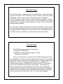
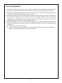
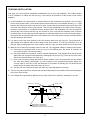
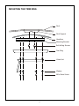
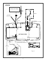
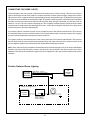
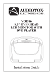
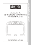
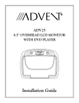
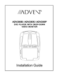
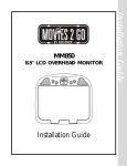
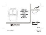
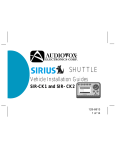
R
ADV285 S / ADV285 P
DUAL 8.5" OVERHEAD
LCD MONITOR WITH
DUAL DVD PLAYER
Installation Guide
Important Notice
An LCD panel and / or video monitor may be installed in a motor vehicle and
visible to the driver if the LCD panel or video monitor is used for vehicle
information, system control, rear or side observation or navigation.
If the LCD panel or video monitor is used for television reception, video or
DVD play, the LCD panel or video monitor must be installed so that these
features will only function when the vehicle is in “park” or when the vehicle’s
parking brake is applied.
An LCD panel or video monitor used for television reception, video or DVD
play that operates when the vehicle is in gear or when the parking brake is
not applied must be installed to the rear of the driver’s seat where it will not
be visible, directly or indirectly, to the operator of the motor vehicle.
Important Note
The ADV285 incorporates two new features:
1) A wireless FM Modulator
2) Capability to add an optional plug-in TV tuner
(Audiovox P/N PODTVT)
Please be advised that the wireless FM modulator will perform well in
most applications. However, in certain applications the quality of the wireless
signal may be less than optimal, resulting in static or strong local station
bleed thru. If this is the case, an optional relay box is available. The
Audiovox part number is SIRSWB and it plugs into the 1/8" jack located
next to the FM antenna on the side of the chassis. This relay box is
installed between the vehicle antenna and the car radio to provide the
best possible FM reception of the DVD player audio. When the SIRSWB is
installed it is recommended that the wireless FM antenna that is plugged
into the printed circuit board next to the 3.5mm jack be unplugged.
MATERIALS INCLUDED IN THIS PACKAGE:
1)
2)
3)
4)
5)
6)
7)
8)
ADV285S/P TV / Video Monitor with DVD – (1 pc)
12 Pin Power / Signal harness (P/N 112-3483) – (1 pc)
2 Pin Power Wire Harness with choke (P/N 112B3143) – (1 pc)
Hardware Package
#4 x 5/16" Self Tapping Screws – (9 pcs)
#8 x 3/8" Self Drilling Screws – (6 pcs)
M5 x10mm Screws – (6 pcs)
M5 Flat Washer – (6 pcs)
Remote Control (P/N 136-4120) – (1 pc)
Trim Ring – (1 pc)
Game Controller (P/N 136-4212) (1 pc)
Mounting Bracket (P/N 108-3895) – (1 pc)
Optional Accessories
9) PODTVT TV Tuner (P/N 136-3877) – (1 pc) (Optional)
10) SIRSWB Relay Box (P/N 112C3159) (1pc) (Optional) – See important note on previous page
1
3
2
4
8
6
7
5
9
10
(Optional)
(Optional)
TOOLS REQUIRED:
#2 Phillips Screwdriver
#1 Phillips Screwdriver
Utility or Razor Knife or Shears
Wire Strippers
Upholstery hook tool (for removal of panels as necessary)
Electrical Tape
Masking Tape
Multimeter (to verify 12 volt DC and continuity: Do not use a test light or logic probe)
Marker pen – to mark headliner
Scribe (to mark trim ring if used)
Misc. electrical connectors (to connect to vehicle power source). Requirements will vary from vehicle to
vehicle)
DVD Movie (to verify system operation after installation)
1
GENERAL INSTALLATION APPROACH:
1) Decide upon system configuration and options that will be installed (i.e.: what components, VCP, Video
Game, external amp, wireless headphones, VCP, etc.).
2) Review all manuals to become familiar with electrical requirements and hook ups.
3) Decide upon mounting locations of all components and method of mounting.
4) Prep the vehicle by removing any interior trim necessary to gain access to vehicle's wiring as well as all
areas where interconnecting wire harnesses will need to be located. If any access holes need to be cut into
the vehicle (headliner, other trim components etc.), this should be done now as well. (Refer to Page3).
5) Route the wiring harnesses throughout the vehicle as necessary. (Refer to the Wiring Diagrams on
this manual as well as the wiring instructions for the individual components and accessory options
being installed). Be sure that all wiring is protected from sharp edges and is routed in such a manner that
pinched when all components and interior trim are fully installed. Be sure to leave enough slack in the wiring
at each component to allow working room.
6) Remove all A/V system components from their packaging and place them loosely in the vehicle at their
respective locations.
7) Connect all components together (electrically) and verify proper operation of all system functions.
Note: This is best done BEFORE, components have been permanently mounted.
8) After verifying proper operation of the system, proceed to mount of each component.
9) When all components are mounted, recheck function of entire system again to ensure that no wiring was
pinched or connected improperly during final installation.
GENERAL SYSTEM CONFIGURATIONS:
The following is intended to provide some of the system configurations that are possible with the ADV285
series Drop Down Video Systems:
Notes:
There are a few audio output options that can be added as follows:
a) Wireless Headphones (P/N IR2CHS).
b) Wired relay box for wireless FM Modulator (P/N SIRSWB).
The ADV285 video system is only intended for an overhead, drop down installation. It is not intended for
Seatback or any other type of mounting. The hinging mechanism is designed for horizontal, drop down
use only.
2
VEHICLE PREPARATION:
1) Locate an accessory power source (+12v when key is in the ACC. and run positions, and 0v when key is
off), and also a good ground generally, these wires can be found at the ignition switch or fuse-box.
2) The mounting method and location will vary from vehicle to vehicle, so this manual will only focus on the
installation of the ADV285 and related console accessories.
3) Generally, the best location for the video monitor is where the vehicle's factory dome light is installed. The
monitor should be located in such a manner that it can be comfortably viewed by rear seat passengers.
NEVER INSTALL THE MONITOR IN A PLACE WITHIN THE DRIVER'S VIEW. THIS IS NOT ONLY
DANGEROUS, BUT IT IS ALSO ILLEGAL IN MANY STATES.
4) Once the mounting location of the monitor has been determined, there may be additional preparation work
necessary, depending on the vehicle structure and installation method. Some of the steps that may be
required are:
A) Removal of the vehicle's dome light
B) If the trim ring will be used, it may have to be trimmed to fit the contour of the vehicle's headliner.
Refer to the "Trim Ring Installation" section in this manual.
3
TRIM RING INSTALLATION:
This page only covers special installation considerations for the trim ring installation. If the video monitor
is to be installed in a vehicle with the trim ring, it may need to be trimmed to fit the contour of the vehicle
headliner.
1) In this installation, the video monitor is mounted directly to the overhead cross-member in the roof using
the mounting screw bosses. These screw bosses should contact the cross-member directly (i.e.: no gap
between the screw boss and the roof structure). Also, be sure that the screws do not pierce the outer roof
skin when fully fastened to the cross-member. The trim ring is attached to the video monitor using the
perimeter screw bosses. It is important that the screws used in this installation are not over tightened,
and that the video monitor and trim ring are mounted in such a way that the assembly does not distort
(or bend) when the mounting screws are tightened. An alternate method is to use the mounting bracket.
First secure the mounting bracket to the cross-member, then screw the monitor into the mounting bracket.
See the drawing in this manual.
2) It is best to mount the video monitor to the roof structure without the trim ring first. There should be a
gap between the headliner and the outer flange of the video monitor. The trim ring should be cut to fill
this gap. Apply masking tape to the outer surface of the trim ring in the areas where the cut will be made.
3) Mark the cut to follow the necessary contour of the roof. The suggested method of marking is as follows:
A) First mark the narrowest point of the trim ring on the masking tape. Be careful to consider not
only vertical location, but fore-aft location.
B) Using the handle of a screwdriver, make a “transfer marking tool”. See diagram below. Place the tool
against the roof and the marker against the masking tape on the trim ring. Trace the cut to be made
around the entire perimeter of the trim ring.
C) Cut the trim ring using a sharp utility knife or shears. Make the cut in several passes over the marked
line, each time cutting a little deeper. It is not necessary to cut completely through the plastic, the
cut only need be over 50% of the wall thickness of the plastic. By bending the cut back and forth
several times, the plastic will break cleanly at the cut.
D) Check the fit of the trimmed console and make any minor adjustments necessary.
4) The trim ring can be painted or covered with a material that matches the headliner before assembling the
trim ring to video monitor.
5) The finished trim ring should be attached to the video monitor, then attach the assembly to the roof.
Headliner
Cut line
Lowest point mark
Tape marker to screwdriver.
Starting at your mark for the
lowest point, trace the contour of the roof
4
MOUNTING THE TRIM RING
Roof
Roof Support
Headliner
Mounting Bracket
Self-drilling Screws
Trim Ring
Video Unit
Washer
M5 x10mm Screw
5
ADV285
Auxillary Video Display
TV
ANTENNA
Line Out-R (Red)
Line Out-L (White)
Line Out-V (Yellow)
Power
Harness
Item #3
(Optional)
Dome Light
Power source
To TV Antenna In
Power Harness
Item #3
*** Optional PODTVT
(See TV Tuner Note on next page)
DIN 1 (AV1)
PODTVT
UNIT (BACK VIEW)
DIN 2
* Antenna for Wireless FM Mod.
** See Antenna Note on the next page
Accessory
Harness - Optional
(P/N:8010730)
* Optional Relay Box
SIRSWB
(Optional)
Red RCA (Audio Right)
White RCA (Audio Left)
Yellow RCA (Video)
Power Connector
4 Pin
Clean the IR Receiver Window on the front of the VCP.
Remove Adhesive Backing and Apply IR LED to IR
"Y" Adapter
for use with
Non-Stereo
Installations
Item# 5
Figure A
ANT.IN
FUSE
DC IN
RF OUT
OUT
6
ADV285
1) Make the connections to the vehicle for the 12 pin wiring harness.
2) Connect power harness to vehicle’s electrical system by tapping into an accessory hot line and a good
ground.
3) Connect the 12 pin harness to the mating connector on the Video Monitor.
4) If an auxiliary video input is used (VCP, DVD, etc) insert the Circular Mini-Din Connector of the source
component harness through the wire tie loop on the main PCB and into the Mini-Din Connector on the main
PCB.
5) Pull the wire tie loop tight and cut off the excess.
Note: A VCP or other A/V Component can be connected to the video monitor system using a source
component harness (purchased separately, part number: 8010730). This harness plugs into the Mini-Din
connector on the main PCB as in steps 4 and 5 above.(See Figure A on previous page)
6) Verify all functions of the System before final mounting of the finished assembly.
7) Mount and connect the Television antenna. (Optional)
A/V Source Definitions:
1. DVD1 – Built in DVD
2. DVD2 – Built in DVD
3. AV1 (DIN1)
4. AUX/Game
5. AV2/ TV – When PODTVT is used the AV2 input position becomes inactive (DIN2).
*NOTE: If the optional relay box P/N SIRSWB is installed, it recommended that the antenna for the wireless FM
Modulator be unplugged. See ADV285 Wiring Diagram for antenna location.
**NOTE: Extending the wireless antenna beyond its 12 inch length will cause the FM Modulator to exceed FCC
limits for wireless transmission. When installing the unit position the antenna for best reception.
***NOTE: If the optional TV Tuner (P/N PODTVT) is installed the AV2 (DIN2) input becomes inactive.
7
CONNECTING THE DOME LIGHTS
The dome lights in the video monitor require three connections to the vehicle's wiring. There are two common
types of dome light circuits used, positive or negative switched. Positive systems supply voltage to the interior
lights to turn them on, negative switched systems apply ground to illuminate the bulbs. To determine which system
you have you must locate the wires at the dome light. On a positive switched system, with all the doors closed and
the lights out, both wires at the dome light will rest at ground. When the light is activated, one of these wires will
switch to +12 vdc. This is the vehicle's switching wire. On a negative switched system, with all the doors closed
and the lights out, both wires at the dome light will rest at + 12vdc. When the light is activated, one of these wires
will switch to ground. This is the switching wire.
For positive systems, connect the purple / brown (Lamp auto) wire to the vehicle's switched wire. Then connect
the red / black (lamp on) wire to a fused constant 12 volt source and the black / red (lamp common) wire to a good
ground. Positive systems are commonly found on Ford vehicles.
For negative systems, connect the purple / brown (Lamp auto) wire to the vehicle's switched wire. Then connect
the red / black (lamp on) wire to a good ground and the black / red (lamp common) wire to fused constant 12 volt
source. Negative systems are commonly found on General Motors and import vehicles.
Note: Some vehicles which incorporate transistorized control of the dome light circuit, such as the 1999 Dodge
Caravan, may require that the purple / brown (Lamp auto) wire be connected to the door pin switch wire, as the
additional current draw of the Monitor's lights may not be supported by the output of the vehicles body control
computer.
Positive Switched Dome Lighting
To 12 pin
connector
on Monitor
Red / black - Lamp on
Black / red - Lamp common
Purple / brown - Lamp Auto
Factory Dome light circuit
To
constant
+12vdc
Factory Door ajar
switch or Body
Control computer
8
To
constant
+12vdc
Negative Switched Dome Lighting
To 12 pin
connector
Red / black - Lamp on
Black / red - Lamp common
Purple / brown - Lamp Auto
To
constant
To
constant
Factory Door ajar
switch or Body
Control computer
Troubleshooting:
SYMPTOM:
REMEDY:
No power at Video Monitor
Verify +12 VDC on Red wire at 2 pin Power Harness behind video
monitor. Verify ground connection with continuity test from known good
ground to black wire at 2 pin Power Harness
Power but no video or sound
Verify that the correct source is selected (i.e.: 1,2,3 or 4). Verify that the
source is on and playing a known good media (such as a videotape).
Verify connections at both ends of the source component harness.
Static on TV Stations
(Tuner Version Only)
Press Auto Program button. Then press CH up or CH down. Verify
antenna mounting and connections to the tuner.
Note: Due to the nature of TV signals, vehicle motion, direction the
vehicle is facing, distance from the transmitter, nearby surroundings and
weather may adversely affect TV reception. These conditions may result
in the following: picture roll, "snowy" picture, or momentary loss of color.
No Infrared remote functions Check batteries in the hand held remote. Verify that the IR LED
for VCP (or other components) (page 6 Wiring Diagram) is properly attached to the sensor window of
the VCP (or other component).
9
128-7545A
© 2005 ADVENT, 150 Marcus Blvd. Hauppauge, NY 11788