1
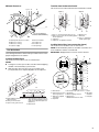
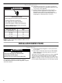
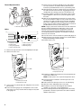
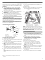
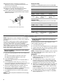
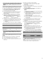
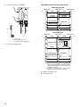
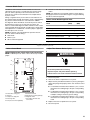
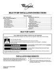
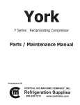
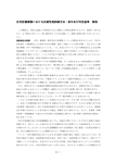
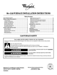
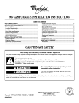
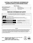
HEAT PUMP INSTALLATION INSTRUCTIONS
Table of Contents
HEAT PUMP SAFETY.....................................................................1
INSTALLATION REQUIREMENTS ................................................1
Tools and Parts ............................................................................2
System Requirements..................................................................2
Location Requirements ................................................................2
Electrical Requirements ...............................................................4
INSTALLATION INSTRUCTIONS ..................................................4
Inspect Shipment .........................................................................4
Flush Refrigerant Lines ................................................................5
Connect Refrigerant Lines ...........................................................7
Charge Refrigerant Lines .............................................................8
Make Electrical Connections .....................................................11
Complete Installation .................................................................13
SEQUENCE OF OPERATION ......................................................14
Cooling Cycle .............................................................................14
Heating Cycle .............................................................................14
Defrost Cycle..............................................................................14
Adjust Defrost System ...............................................................15
Troubleshoot the Defrost System ..............................................16
TROUBLESHOOTING ..................................................................16
System Diagnostic Module ........................................................16
SYSTEM MAINTENANCE ............................................................18
ASSISTANCE OR SERVICE .........................................................18
Accessories ................................................................................18
WARRANTY ..................................................................................19
HEAT PUMP SAFETY
Your safety and the safety of others are very important.
We have provided many important safety messages in this manual and on your appliance. Always read and obey all safety
messages.
This is the safety alert symbol.
This symbol alerts you to potential hazards that can kill or hurt you and others.
All safety messages will follow the safety alert symbol and either the word “DANGER” or “WARNING.”
These words mean:
DANGER
WARNING
You can be killed or seriously injured if you don't immediately
follow instructions.
You can be killed or seriously injured if you don't follow
instructions.
All safety messages will tell you what the potential hazard is, tell you how to reduce the chance of injury, and tell you what can
happen if the instructions are not followed.
INSTALLATION REQUIREMENTS
These instructions are intended as a general guide only for use by
qualified persons and do not supersede any national or local
codes in any way. The installation must comply with all state and
local codes as well as the National Electrical Code.
Whirlpool Gold® Model W4GH6
48488D008
■
■
The heat pump is designed and approved for outdoor use
only.
The heat pump must be installed with no ductwork in the
airstream. The outdoor fan is not designed to operate against
any additional static pressure.
Tools and Parts
Gather the required tools and parts before starting installation.
Read and follow the instructions provided with any tools listed
here.
Tools Needed
■
■
■
■
Torch
¹⁄₄" nut driver
⁵⁄₁₆" nut driver
Adjustable wrench
■
■
■
Gauge set for R-410A
refrigerant
Service wrench with hexhead extension
Torque wrench
Parts Needed
Check local codes and HVAC supplier. Check existing electrical
supply, and read “Electrical Requirements,” “Location
Requirements,” “System Requirements” and “Connect
Refrigerant Lines.”
System Requirements
Heat pump system matches are derived from actual laboratory
testing of matched systems. It is recommended that only matching
equipment be used to ensure proper operation and efficient
performance.
■ The designed system matches are listed in the heat pump unit
specification sheets. Refrigerant charging instructions are
located on the back of the service access panel.
■ This heat pump has been factory charged with a quantity of
refrigerant (R-410A) sufficient for a matched indoor coil and a
maximum 15 ft (4.6 m) of refrigerant line.
■ In order to maintain the SEER rating, this heat pump must be
matched with an indoor section containing a variable speed
blower.
■ Refer to the Thermal Expansion Valve Kits chart to determine
the correct size thermal expansion valve required.
■ This product has been designed and manufactured to meet
ENERGY STAR® qualification for energy efficiency when
matched with appropriate coil components. However, proper
refrigerant charge and proper airflow are critical to achieve
rated capacity and efficiency. Installation of this product
should follow the manufacturer’s refrigerant charging and
airflow instructions. Failure to confirm proper charge and
airflow may reduce energy efficiency and shorten equipment
life.
■
■
■
A filter dryer approved for use with R-410A refrigerant is
installed in the heat pump.
If this heat pump is equipped with a crankcase heater, it
should be energized 24 hours before the heat pump is started
to avoid compressor damage as a result of slugging.
Use only polyol ester oils if oil must be added to the system.
Mineral oil is not compatible with refrigerant.
Indoor System Thermal Expansion Valve
■
W4GH6 units are designed for use with thermal expansion
valve systems only. The thermal expansion valve must be
ordered separately from the manufacturer.
Thermal Expansion Valve Kits
Model
Part Number
W4GH624
H4TXV01
W4GH636
H4TXV02
W4GH648, W4GH660
H4TXV03
Location Requirements
■
■
■
2
This heat pump is designed to be located outdoors with
sufficient clearance for free entrance to the inlet and
discharge air openings. The location must also allow for
adequate service access. See “Minimum Clearances.”
Where possible, select a location for the heat pump which is
shaded from the direct rays of the sun most of the time. North
or east locations are usually most desirable. Position the heat
pump to avoid direct contact with water, snow or ice from a
roofline overhead.
The heat pump must be installed on a solid, level mounting
pad that will not settle or shift. Isolate the pad from the
building structure to avoid possible transmission of sound or
vibration from the heat pump into the conditioned space.
■
■
■
The heat pump foundation should be raised to a minimum of
3" (7.6 cm) above finish grade. In areas which have prolonged
periods of temperatures below freezing, and/or snowfall, the
heat pump should be elevated above the average snow line.
If heat pump is to be installed on a flat roof, it should be on a
platform or other support which will raise the inlet air opening
12" (30.5 cm) minimum above the surface of the flat roof.
Avoid ice accumulation by ensuring free drainage of
condensate from defrost cycles. The heat pump should be
located away from walkways to avoid possible icing from
defrost condensate.
Avoid placing the heat pump near areas such as sleeping
quarters or study rooms. Normal operating sound levels may
be objectionable if the heat pump is placed near certain
rooms. A shift in sound type does occur during the defrost
mode. The defrost mode generally lasts no longer than
10 minutes.
Transition from Horizontal to Vertical
Minimum Clearances
A B
C
This shows how to make a transition from horizontal to vertical.
E
Style 1
D
48" (121.9 cm)
Overhead Clearance
(Discharge Air)
)
cm r)
5
i
.
30 t A
" ( le
12 e (In
nc
ra
ea
Cl
Style 2
A
F
G
G
B
B
C
C
H
F
Cl 36
ea "
ra (91
nc .4
e ( cm
Inl )
et
Ai
r)
ice
erv ce
S
)
n
cm ra
.2 lea
76 ss C
(
"
30 cce
A
A. Weatherproof disconnect switch
B. NEC class 1 wiring
C. NEC class 2 wiring
D. To power supply
12" (30.5 cm) Clearance
Between Unit and Building
E. House thermostat
F. To indoor unit
G. To indoor coil
H. Seal openings
Line Set Isolation
F
D
E
A. Style 1—anchored heavy nylon wire tie
E. Metal sleeve
B. Tape or heavy nylon wire tie holding liquid F. Wall stud
line to vapor line.
G. Style 2—automotive
C. Liquid line
muffler-type hanger
D. Vapor line—wrapped in armaflex
Installing Vertical Runs (new construction shown)
This shows how to install line sets on vertical runs.
NOTE: Similar installation practices should be used if line set is
to be installed on exterior of outside wall.
IMPORTANT: Refrigerant lines must not contact structure.
The following illustrations demonstrate procedures which ensure
proper refrigerant line set isolation.
B
A
C
Installing Horizontal Runs
This shows how to install line sets on horizontal runs.
NOTES:
■ To hang line set from joist or rafter, use either metal strapping
material or anchored heavy nylon wire ties.
■ Strap the vapor line to the floor joist or roof rafter at 8 ft
(2.4 m) intervals, then strap the liquid line to the vapor line.
D
D
G
A
8'
B
J
E
L
D
A
C
A. Metal strapping material (around D. Metal strapping material (around
vapor line only)
vapor line only) and tape or heavy
nylon wire tie (around vapor and
B. Floor joist or roof rafter
liquid lines)
C. Tape or heavy nylon wire tie
E. Metal sleeve
E
F
G
H
E
I
C
8'
C
H
C
A
D
E
K
D
E
G
H
E. Anchored heavy nylon wire tie J. Caulk
A. Outside wall
K. Fiberglass
B. Space between wall F. Inside wall
insulation
and refrigerant line
G. Metal strapping material
L. PVC pipe
C. Vapor line wrapped H. Metal sleeve
in armaflex
I. Wood block between studs
D. Liquid line
3
Electrical Requirements
■
WARNING
■
All field wiring must be done in accordance with National
Electrical Code requirements, applicable requirements of UL,
or local codes, where applicable.
Electrical wiring, disconnect means and over-current
protection are to be supplied by the installer. Refer to the
rating plate for the maximum over-current protection,
minimum circuit ampacity, and operating voltage. See the
wiring diagrams in “Make Electrical Connections.”
Electrical Shock Hazard
Electrically ground condensing unit or heat pump.
Connect ground wire to ground lug.
Use copper wire for supply connection.
Correct wire gauge is shown in the chart below.
Failure to follow these instructions can result in
death or electrical shock.
Rating Plate Ampacity
AWG
Less than 15
14
16 - 20
12
21 - 30
10
31 - 50
8
NOTE: All outdoor wiring must be suitable for outdoor use. Use
copper conductors only.
INSTALLATION INSTRUCTIONS
Inspect Shipment
WARNING
Excessive Weight Hazard
Use two or more people to move and install
condensing unit or heat pump.
Failure to do so can result in back or other injury.
This heat pump is shipped in one package, completely
assembled and wired. The thermostat is shipped in a separate
carton when ordered.
4
1. Check the heat pump rating plate to confirm specifications
are as ordered.
2. Upon receipt of heat pump, inspect it for possible shipping
damage. Examine the heat pump inside the carton if the
carton is damaged.
If damage is found, it should be noted on the carrier’s freight bill.
Damage claims should be filed with the carrier immediately.
Claims of shortages should be filed with the seller within 5 days.
NOTE: If any damages are discovered and reported to the carrier,
do not install the heat pump because your claim may be denied.
Flush Refrigerant Lines
Refrigerant lines must be flushed by a licensed, EPA certified
refrigerant technician in accordance with established procedures.
NOTES:
■ R-410A outdoor systems are not recommended for use with
indoor systems that have used R-22 as the refrigerant.
However, if this heat pump is being matched with an
approved line set or indoor coil which was previously charged
with R-22 refrigerant, or if it is being matched with a coil
which was manufactured before January 1999, the R-22 coil
and line set must be flushed prior to installation.
■ Check the refrigerant lines for size and length. See “Connect
Refrigerant Lines.”
■
■
Polyol ester (POE) oils are used in Whirlpool units charged
with R-410A refrigerant. Residual mineral oil from the R-22
system can act as an insulator, inhibiting proper heat transfer.
It can also clog the thermal expansion valve, reducing system
performance and capacity.
Failure to properly flush the system according to the following
instructions will void the warranty.
Tools and Parts
2 clean R-22 recovery
cylinders
Oilless recovery machine
with a “pump down” feature
■
■
■
■
Gauge set for R-22
refrigerant
Gauge set for R-410A
refrigerant
Flushing Connections
NOTE: The inverted R-22 cylinder must contain at least the same amount of refrigerant as was recovered from the existing system.
C
F
A
S
R
Q
B
D
L
K
G
H
E
J
I
M
N
O
P
A. Existing indoor coil
B. Existing vapor line
C. Inverted R-22 cylinder (contains clean R-22 to
be used for flushing)
D. Vapor line service valve
E. Outdoor system
F. Low pressure
G. High pressure
H. Gauge manifold
I. Closed
J. Opened
K. Liquid line service valve
L. Existing liquid line
M. Tank return
1. Disconnect power.
2. Remove the refrigerant from the existing system according to
the manufacturer’s instructions provided with the recovery
system being used. Connect the R-22 gauge set is
connected to both sides of the refrigerant system (as shown),
and verify that the entire system is void of refrigerant in
accordance with the manufacturer’s instructions provided
with the recovery system being used.
3. Disconnect the liquid and vapor lines from the existing
outdoor unit.
N. Inlet
O. Discharge
P. Recovery machine
Q. Recovery cylinder
R. Vapor
S. Liquid
4. Remove the existing outdoor unit.
5. Set the new R-410A outdoor unit and connect the refrigerant
lines. See “Connect Refrigerant Lines” steps 1 through 5. Do
not evacuate the lines.
6. Remove the existing R-22 refrigerant flow control orifice and
reconnect piping or remove thermal expansion valve on the
indoor coil, and use a field provided fitting to reconnect the
lines.
5
Thermal Expansion Valve
A
A. Thermal expansion valve
Orifice
A
B
C
D
G
E
F
A. Distributor fitting
B. Piston orifice
C. Ring seal (supplied)
D. Orifice extension stub
11. Set the recovery machine for liquid recovery and start the
recovery machine in accordance with the manufacturer’s
instructions provided with the recovery system being used.
12. Open the gauge set valves to allow the recovery machine to
run until a vacuum level less than 0" Hg (gauge pressure) is
established in the existing system line set and indoor coil.
13. Invert the cylinder of clean R-22 and open its valve to allow
liquid refrigerant to flow into the system through the vapor
line valve.
14. After all of the liquid refrigerant has been recovered, switch
the recovery machine to vapor recovery to allow the recovery
machine to run until a vacuum level less than 0" Hg (gauge
pressure) is established in the existing system line set and
indoor coil in accordance with the manufacturer’s instructions
provided with the recovery system being used.
NOTE: A single system flush should remove all of the mineral oil
from the existing refrigerant lines and indoor coil. A second
flushing may be done (using clean refrigerant) if insufficient
amounts of mineral oil were removed during the first flush. A
second flushing may be required to ensure that the maximum
amount of oil is removed.
15. Close the valves on the inverted R-22 cylinder and gauge set.
16. Remove the recovery machine, gauges, R-22 cylinder and the
field provided fitting installed in Step 6.
17. Install the valve cores.
E. 0.812" brass hex nut
F. Brass hex fitting
G. Mounting flange
A
7. Remove the caps from the suction and liquid pressure taps.
8. Remove the valve cores.
B
A
B
A. Suction pressure tap
B. Liquid pressure tap
18. Install the R-410A thermal expansion valve specified for this
system in the indoor coil.
NOTE: R-410A systems use only thermal expansion valves.
A. Suction pressure tap
B. Liquid pressure tap
9. Connect an R-22 cylinder with clean refrigerant to the suction
pressure tap.
10. Connect the R-22 gauge set to the liquid line service valve
and connect a recovery machine with an empty recovery tank
to the gauge set.
6
19. Pressurize the lines and indoor coil with a pressure not to
exceed 20 psig.
20. Leak test the lines with a pressure not to exceed 20 psig.
21. Open the suction and liquid service valves fully.
22. Insulate the suction line with refrigerant line insulation
material of ¹⁄₄" (6.4 mm) or more wall thickness.
23. Pack insulating material around refrigerant lines where they
penetrate the structure to protect the lines and to minimize
vibration transmission.
Connect Refrigerant Lines
Refrigerant lines must be connected by a licensed, EPA certified
refrigerant technician in accordance with established procedures.
IMPORTANT:
■ Connecting refrigerant lines must be clean, dehydrated,
refrigerant-grade copper lines. Heat pumps should be
installed only with specified line sizes for approved system
combination. See the Suction Line Sizes and Liquid Line
Sizes charts later in this section.
■ Avoid sharp bends or possible kinking in the refrigerant lines
during installation as this may cause a reduction in
performance.
■ To avoid contamination of the refrigerant system, do not
remove the caps from the lines or system connection points
until connections are ready to be completed.
7. Connect the external equalizer line to the equalizer port on
the suction line.
8. Tighten to 8 ft/lbs.
9. Attach the superheat sensing bulb to the suction header with
the strap provided with the thermal expansion valve.
A B
F
C
E
Install Thermal Expansion Valve
W4GH6 heat pumps are designed for use with thermal expansion
valve systems only. An R-410A system will not operate properly
with an R-22 thermal expansion valve.
Thermal expansion valves equipped with Chatleff-type fittings are
available from the manufacturer. See Thermal Expansion Valve
Kits chart in “System Requirements.”
A. Equalizer port
B. Superheat sensing bulb
C. Thermal expansion valve
Thermal Expansion Valve Installation
A
B
C
F
D. Liquid line
E. Suction line
F. Equalizer line
NOTE: If installing a thermal expansion valve on an indoor coil
that previously used a fixed orifice, be sure to remove the existing
fixed orifice. Failure to remove a fixed orifice when installing a
thermal expansion valve to the indoor coil may result in improper
operation and damage to the system.
Connect Liquid and Suction Lines
E
D
A. Distributor
B. Teflon® seal
C. Thermal expansion valve
D
D. Liquid line stub
E. Strainer
F. Teflon® seal
To install the thermal expansion valve:
1. Separate the distributor assembly.
2. If a piston orifice is installed, remove the piston orifice and old
Teflon® seal and discard.
3. Insert nozzle end of the thermal expansion valve along with a
new Teflon® seal into the distributor.
4. Tighten to 20 to 30 ft/lbs. Use backup wrench on all wrench
flats.
NOTE: Overtightening may crush the Teflon® seal and cause
a leak.
5. Attach liquid line portion of distributor assembly along with
new Teflon® seal to the inlet of the thermal expansion valve.
6. Tighten to 20 to 30 ft/lbs. Use backup wrench on all wrench
flats.
NOTE: Overtightening may crush the Teflon® seal and cause
a leak.
1. Route the suction and liquid lines from the fittings on the
indoor coil to the fittings on the heat pump. Run the lines in
as direct a path as possible, avoiding unnecessary turns and
bends.
2. For product efficiency, be sure that the suction line is
insulated over the entire exposed length and that both
suction and liquid lines are not in direct contact with floors,
walls, ductwork, floor joists, or other piping.
3. Remove valve cores.
4. Wrap the service valves with a wet rag.
5. Connect the suction and liquid lines, using a brazing
compound. Braze with an alloy of silver or copper and
phosphorus with a melting point above 1,100°F (593ºC).
NOTE: Do not use soft solder.
6. Make sure indoor coil has been put in place according to the
Installation Instructions and is connected to the refrigerant
lines.
7. Replace valve cores.
8. Pressurize the lines and indoor coil with a pressure not to
exceed 20 psig.
9. Leak test the lines with a pressure not to exceed 20 psig.
®Teflon is a registered trademark of E.I. Dupont de Nemours and
Company.
7
10. Evacuate the indoor coil and lines to a minimum of
500 microns to remove contamination and moisture, then
disconnect the vacuum pump.
11. Open the suction and liquid service valves fully.
12. Insulate the suction line with refrigerant line insulation
material of ¹⁄₄" (6.4 mm) or more wall thickness.
13. Pack insulating material around refrigerant lines where they
penetrate the structure to protect the lines and to minimize
vibration transmission.
A
Suction Line Sizes
Installations exceeding 100 ft (30.5 m) are not recommended.
Btu/h
Line Set Size—in. (cm) OD
24,000
³⁄₄ (1.9)
³⁄₄ (1.9)
³⁄₄ (1.9)
36,000
⁷⁄₈ (2.2)
⁷⁄₈ (2.2)
⁷⁄₈ (2.2)
48,000
⁷⁄₈ (2.2)
⁷⁄₈ (2.2)
1¹⁄₈ (2.9)
60,000
1¹⁄₈ (2.9)
1¹⁄₈ (2.9)
1¹⁄₈ (2.9)
Line Set
Length
Less than Over 25 ft (7.6 m)
25 ft
and up to 75 ft
(7.6 m)
(22.9 m)
Over 75 ft (22.9 m)
and up to 100 ft
(30.5 m)
Liquid Line Sizes
Installations exceeding 100 ft (30.5 m) are not recommended.
A. Insulating material around refrigerant lines
Btu/h
Line Set Size—in. (cm) OD
24,000
³⁄₈ (1)
³⁄₈ (1)
³⁄₈ (1)
36,000
³⁄₈ (1)
³⁄₈ (1)
³⁄₈ (1)
48,000
³⁄₈ (1)
³⁄₈ (1)
¹⁄₂ (1.3)
60,000
³⁄₈ (1)
³⁄₈ (1)
¹⁄₂ (1.3)
Line Set Less than Over 25 ft (7.6 m)
Length 25 ft
and up to 75 ft
(7.6 m)
(22.9 m)
Over 75 ft (22.9 m)
and up to 100 ft
(30.5 m)
Charge Refrigerant Lines
NOTE: Refrigerant lines must be charged by a licensed, EPA
certified refrigeration technician in accordance with established
procedures.
The outdoor condensing unit should be charged during warm
weather. However, applications arise in which charging must
occur in the colder months. The method of charging is
determined by the system’s refrigerant expansion device and the
outdoor ambient temperature. Choose one of the following
charge methods based on the system’s refrigerant expansion
device and the outdoor ambient temperature.
Measure the Liquid Line Temperature and the Outdoor
Ambient Temperature
1. Connect the manifold gauge set to the service valve ports as
follows:
■ Low pressure gauge to suction line service valve
■
High pressure gauge to liquid line service valve
2. Close manifold gauge set valves.
3. Connect the center manifold hose to an upright cylinder of
refrigerant (R-22).
4. If room temperature is below 70°F (21ºC), set the room
thermostat to call for heat. This will create the necessary load
for properly charging the system in the cooling cycle.
5. When the heating demand has been satisfied, switch the
thermostat to cooling mode with a set point of 68°F.
6. When pressures have stabilized, use a digital thermometer to
record the liquid and suction line temperatures.
7. Use a digital thermometer to record the outdoor ambient
temperature.
NOTE: The outdoor temperature will determine which charging
method to use.
8
Charge Using Weigh-In Method (Thermal Expansion
Valve Systems)
Use this method if the system is void of refrigerant, or if the
outdoor ambient temperature is cool.
1. Locate and repair any leaks.
2. If necessary, recover the refrigerant from the condensing unit.
3. Conduct a leak check, then evacuate as previously outlined.
4. Weigh in the charge according to the total amount shown on
the condensing unit nameplate.
NOTE: If weighing facilities are not available or if the condensing
unit is being charged during warm weather, follow one of the
other charging methods.
IMPORTANT:
■ Refrigerant charge adjustment will be required for line set
lengths greater than 15 ft (4.6 m) and for non systemmatched evaporator coils.
■ The condensing unit is factory-charged with the proper
refrigerant charge amount for a matching evaporator and
15 ft (4.6 m) of refrigerant line. Refer to the condensing unit
rating plate for the exact amount of this factory charge.
■ Adjustment of the refrigerant charge will be necessary based
on the system combination and line length. To adjust the
refrigerant size for increased line lengths, add the following
amount of refrigerant.
For line set lengths greater than 15 ft (4.6 m), add refrigerant
by weighing in 0.60 oz per ft of ³⁄₈" (1 cm) O.D. liquid line.
■
If necessary, adjust the refrigerant charge for compatibility
with the evaporator coil.
Monitor system pressures while charging.
1. Record outdoor ambient temperature using a digital
thermometer.
2. Attach high pressure gauge set.
3. Operate condensing unit for several minutes to allow system
pressures to stabilize.
4. Compare stabilized pressures with those provided in the
Normal Operating Pressures chart.
NOTES:
■
Charge Using Sub-cooling Method (Thermal Expansion
Valve Systems)—Outdoor Temperatures 65°F (18ºC) or
Above
Use this method if charging a Thermal Expansion Valve system
when the outdoor ambient temperature is 65°F (18ºC) or above.
1. Attach the manifold gauge hose to the liquid service port.
2. If the condensing unit pressures are stable, use a digital
thermometer to record the liquid line temperature.
3. Record the liquid line pressure reading.
4. Use a temperature/pressure chart for refrigerant (R-22) to
determine the saturation temperature for the liquid line
pressure reading.
5. Subtract the liquid line temperature from the saturation
temperature to determine sub-cooling. See Sub-cooling
Values for Thermal Expansion Valve Systems chart.
_____ ° (Saturation Temperature °F) - _____ ° (Liquid Line
Temperature °F) = _____ ° (Sub-cooling Value °F)
6. Compare the sub-cooling value with those shown in Subcooling Values for Thermal Expansion Valve Systems chart.
■ If sub-cooling is greater than shown, recover some
refrigerant.
■
If sub-cooling is less than shown, add some refrigerant.
Sub-cooling Values
Model
W4GH624A
W4GH636A
Temperature ºF
8
7
Model
W4GH648A
W4GH660A
Temperature ºF
9
8
Charge Using Approach Method (Thermal Expansion
Valve Systems)—Outdoor Temperatures 65°F (18ºC) or
Above
Use this method if charging a Thermal Expansion Valve system
when the outdoor ambient temperature is 65ºF (18ºC) or above.
NOTES:
■ The following procedure is intended as a general guide.
■ Use on Thermal Expansion Valve systems only.
■ For best results, indoor temperature should 70°F (21ºC) to
80°F (27ºC).
■
Minor variations in these pressures may be expected due
to differences in installations.
■
Significant differences could mean that the system is not
properly charged or that a problem exists with some
component in the system.
■
Pressures higher than those listed indicate that the
system is overcharged.
■
Pressures lower than those listed indicate that the system
is undercharged.
■
Verify adjusted charge using the approach method.
5. Use the same digital thermometer to check liquid line
temperature.
6. Subtract the outdoor ambient temperature from the liquid line
temperature to determine the approach temperature.
_____ ° (Liquid Line Temperature °F) - _____ ° (Outdoor
Ambient Temperature °F) = _____ ° (Approach
Temperature °F)
7. Compare the approach value with those shown in the
Approach Values for Thermal Expansion Valve Systems chart.
■ If the approach values are too high, add refrigerant to
lower the approach temperature
■
If the approach values are too low, recover refrigerant
from the system to increase the approach temperature.
Approach Values for Thermal Expansion Valve Systems
Model
W4GH624A
W4GH636A
Temperature ºF
8
9
Model
W4GH648A
W4GH660A
Temperature ºF
8
8
Approach value is the liquid line temperature minus the
outdoor ambient temperature (∆°F).
NOTE: For best results, use the same digital thermometer to
check both outdoor ambient and liquid temperatures.
■
9
Check Charge Using Normal Operating Pressures
Use the Normal Operating Pressures chart to perform
maintenance checks.
NOTES:
■ This chart is not a procedure for charging the system.
■
■
Minor variations in these pressures may be due to differences
in installations.
Significant deviations could mean that the system is not
properly charged or that a problem exists with some
component in the system.
Normal Operating Pressures
W4GH624A
Air Temperature Entering
Outdoor Coil ºF (ºC)
Liquid
W4GH636A
W4GH648A
W4GH660A
Suction
Liquid
Suction
Liquid
Suction
Liquid
Suction
Cooling 1st Stage (Low Capacity
65 (18)
232
146
225
144
235
144
225
138
75 (23.9)
264
148
261
147
268
145
264
141
85 (29.4)
307
149
302
149
310
147
305
142
95 (35)
353
151
349
151
356
148
352
146
105 (40.6)
403
153
397
153
407
150
405
148
115 (46.1)
460
155
461
157
466
152
459
150
Cooling—2nd Stage (High Capacity)
65 (18)
240
143
239
139
244
140
241
134
75 (23.9)
279
145
278
141
283
141
280
136
85 (29.4)
322
147
322
143
326
144
324
137
95 (35)
371
149
367
146
374
147
373
138
105 (40.6)
423
151
426
148
427
148
425
142
115 (46.1)
485
154
489
151
491
151
486
146
Heating—1st Stage (Low Capacity)
40ºF
337
93
328
98
369
75
351
63
50ºF
322
117
333
118
366
114
335
92
Heating—2nd Stage (High Capacity)
20º
279
62
296
62
311
58
308
59
30ºF
288
76
309
75
334
72
323
70
40ºF
302
93
322
92
354
89
318
69
50ºF
306
112
336
113
381
108
329
82
NOTE: Values provided are typical pressures. Indoor unit match-up, indoor air quality and indoor load will cause pressures to vary.
10
Make Electrical Connections
Single Phase Electrical Connections
WARNING
Refer to “Outdoor Unit Typical Wiring Diagram.”
WARNING
Electrical Shock Hazard
Electrically ground condensing unit or heat pump.
Connect ground wire to ground lug.
Electrical Shock Hazard
Use copper wire for supply connection.
Correct wire gauge is shown in the chart below.
Failure to follow these instructions can result in
death or electrical shock.
Rating Plate Ampacity
AWG
Less than 15
14
16 - 20
12
21 - 30
10
31 - 50
8
Disconnect power before servicing.
Replace all parts and panels before operating.
Failure to do so can result in death or electrical shock.
1. Disconnect power.
2. Remove control box cover.
3. Connect the field supply wires L1 and L2 to contactor
terminals L1 and L2.
IMPORTANT:
■ Electrical wiring, disconnect means and over-current
protection are to be supplied by the installer. Refer to the
rating plate for the maximum over-current protection,
minimum circuit ampacity, and operating voltage. See wiring
diagrams later in this section.
■ Install an adequately-sized branch circuit disconnect,
according to the NEC, within sight of and readily accessible
from heat pump.
■ The cable or conduit and fittings connected from the
disconnect to the heat pump shall be rated for outdoor use.
11
Typical Wiring Connection (low voltage circuit)
4. Connect ground wire to ground lug.
Without Auxiliary Heat
T2
Indoor Unit
Thermostat
T1
A
Power
R
R
C
W1
R
Common
C
1st Stage
Aux. Heat
Outdoor Unit
Power
C
1st Stage
Aux. Heat
W1
B
W1
W2
L2
L1
W3
G
O
Indoor Blower
G
If Applicable
Reversing Valve
Y1
O
Y1
Y1
Y2
Y2
Compressor
A
Y2
L2
L1
B
With Auxiliary Heat
Indoor Unit
Thermostat
C
A. Ground lug
B. Field supply ground wire
C. 208/230 volt field supply wires
5. Connect low voltage circuit.
A
R
Power
C
E
W1
R
C
Common
R
C
Emergency
Heat Relay
Emergency Heat
1st Stage
Aux. Heat
Outdoor Unit
Power
W1
Outdoor
Thermostat
W1
1st Stage Aux. Heat
W2
W3
G
O
Indoor Blower
G
Reversing Valve
Y1
If Applicable
O
Y1
Y1
Y2
Y2
Compressor
Y2
A. Do not connect C (common) connection between
indoor unit and thermostat except when required
by the indoor thermostat. Refer to the thermostat
installation instructions.
B. C (common) connection between indoor unit and
outdoor unit required for proper operation.
6. Replace control box cover.
7. Reconnect power.
12
B
Outdoor Unit Typical Wiring Diagram
LT BU
R
Y
Dual Capacitor
BU
Outdoor
Fan
Motor
BK
G
R
F C H
R
O-OUT
Y2
R
R
BK
BK
C
R
C
Compressor
Contactor
S
Compressor
Diagnostic
Module
C R
W1
W1
C
24V L
R
DF
Common
O
Y1 OUT
Y1
C
L
R
O
L
LO-PS
BU
Y1 L
R
Sole
R
Y
Thermostat
Fan
Y1 Y2
Y1
Defrost
Control
Y
L2
Ground
Lug
208-230/60/1
L1
Ground
Crankcase
Thermostat
Defrost
Thermostat
Reversing Valve
Compressor
BK
C
S
R
Compressor
Contactor
Diagnostic
Module
208-230/60/1
L Y2 Y1 R
C
Y
R
OR
L2
Crankcaser
Heater
O
HI-PS
Crankcase Heater
L1
W1
L1
Low Pressure
Switch
Defrost Switch
BU
Compressor
Contactor
High
Pressure
Switch
R
Defrost Control
O-OUT
LO-PS
Thermostat
C
Fan
R W1 O Y1 Y2
W1
L
24V
DF
C
L
R
Common
Y1 OUT
O
Y1
HI-PS
Y
LT BU
Equipment
Ground
Defrost
Control
Crankcase
Thermostat
H
BK
R
Fan
LO-PS
PR
C
Low Pressure
Switch
Outdoor
Fan
Motor
Dual
Capacitor
Line Voltage Factory Installed
Line Voltage Field Installed
24 Volt Factory Installed
Class II Voltage Field Installed
BU
BK
G
R
LT BU
Y
PR
HI-PS
High Pressure
Switch
Blue
Black
Green
Red
Light Blue
Yellow
Purple
Complete Installation
1. Operate the heat pump for a period of at least 15 minutes to
allow for pressures and temperatures to stabilize.
2. If heat pump does not appear to be functioning correctly,
have heat pump checked by a person certified by the EPA to
handle refrigerant.
13
SEQUENCE OF OPERATION
Cooling Cycle
Upon cooling demand, the thermostat closes circuit R to O and Y.
Closing R to O and Y energizes the reversing valve for cooling
operation and closes the heat pump contactor, starting the
compressor and outdoor fan. The thermostat automatically
closes R to G circuit, which also brings on the indoor fan at the
same time. Upon satisfying cooling demand, the thermostat will
open the above circuits and open the main contactor, stopping
the compressor and outdoor fan. If the indoor unit is equipped
with a delay timer, the blower will continue to operate for 60 to
90 seconds, which improves system efficiency.
Heating Cycle
Upon heating demand, the thermostat closes circuit R to Y, which
closes the heat pump contactor, starting the compressor and
outdoor fan. The reversing valve is not energized in the heating
mode. The thermostat again automatically brings on the indoor
fan at the same time. Upon satisfying heating demand, the
thermostat opens the above circuits and stops heat pump
operation.
Defrost Cycle
If the outdoor ambient conditions are such that frost forms on the
outdoor coil, the defrost control monitors a defrost cycle. It then
runs the defrost cycle as ambient temperatures require.
The defrost control is time/temperature initiated and temperature
terminated with a maximum defrost time (time-out) of 10 minutes.
The time between defrost cycles is preset at 60-minute intervals
at the factory, but can be field adjusted between 30, 60, or
90 minutes. To adjust the time period between defrost cycles,
see “Adjust Time Between Defrost Cycles” in the “Adjust Defrost
System.”
The defrost control will initiate a defrost cycle when the selected
time period has elapsed and the defrost sensor sees a
temperature below freezing. At the start of a defrost cycle, the
defrost control will energize the reversing valve solenoid, shifting
the reversing valve and de-energizing the outdoor fan. The
defrost relay will also close, energizing temporary heat for
increased comfort during defrost (if the indoor unit is so
equipped). The heat pump will remain in defrost until the defrost
sensor has determined that the frost has been removed from the
coil or a 10-minute period has elapsed, whichever comes first.
Defrost Thermostat
The defrost thermostat is located on the liquid line between the
check/expansion valve and the distributor. When defrost
thermostat senses 42ºF (5.6ºC) or cooler, the thermostat contacts
close and send a signal to the defrost control board to start the
defrost timing. It also terminates defrost when the liquid line
warms up to 70ºF (21.1ºC).
14
Defrost Control
The defrost control board includes the combined functions of the
time/temperature defrost control, defrost relay, diagnostic LEDs
and terminal strip for field wiring connections. See “Defrost
Control Board” in the “Adjust Defrost System” section.
The control provides automatic switching from normal heating
operation to defrost mode and back. During compressor cycle
(call for defrost), the control accumulates compressor run times
at 30, 60 or 90 minute field-adjustable intervals. If the defrost
thermostat is closed when the selected compressor run time
interval ends, the defrost relay is energized and defrost begins.
Defrost Control Timing Pins
Each timing pin selection provides a different accumulated
compressor run time period during one thermostat run cycle. This
time period must occur before a defrost cycle is initiated. The
defrost interval can be adjusted to 30 (T1), 60 (T2) or 90 (T3)
minutes. See “Defrost Control Board” in the “Adjust Defrost
System” section. The defrost timing jumper is factory-installed to
provide a 60-minute defrost interval. If the timing selector jumper
is not in place, the control defaults to a 90-minute defrost
interval. The maximum defrost period is 14 minutes and cannot
be adjusted.
A test option is provided for troubleshooting. The test mode may
be started anytime the heat pump is in the heating mode and the
defrost thermostat is closed or jumpered. If the jumper is in the
test position at power-up, the control will ignore the test pins.
When the jumper is placed across the Test pins for 2 seconds,
the control will enter the defrost mode. If the jumper is removed
before an additional 5-second period has elapsed (7 seconds
total), the heat pump will remain in defrost mode until the defrost
thermostat opens or 14 minutes have passed. If the jumper is not
removed until after the additional 5-second period has elapsed,
the defrost will terminate and the test option will not function
again until the jumper is removed and reapplied.
Compressor Delay
The defrost board has a field-selectable function to reduce
occasional sounds that may occur while the heat pump is cycling
in and out of the defrost mode. The compressor will be cycled off
for 30 seconds while going in and out of the defrost mode when
the compressor delay jumper is removed.
NOTE: The 30-second “off” cycle is not functional when
jumpering the TEST pins.
Time Delay
The time delay is 5 minutes long. The delay helps to protect the
compressor from short cycling in case the power to the heat
pump is interrupted or a pressure switch opens. The delay is
bypassed by placing the timer select jumper across the TEST
pins for 0.5 seconds.
Pressure Switch Circuit
The defrost control includes LO-PS terminals to connect an
optional low pressure (loss of charge pressure) switch. A high
pressure switch (optional) can be connected to the HI PS
terminals. See “Defrost Control Board” in the “Adjust Defrost
System” section.
During a single demand cycle, the defrost control will lock out
the heat pump after the fifth time that the circuit is interrupted by
any pressure switch wired to the control board. In addition,
the diagnostic LEDs will indicate a locked-out pressure switch
after the fifth occurrence of an open pressure switch. See
Defrost Control Board Diagnostic LEDs chart later in this section.
The heat pump will remain locked out until power to the board is
interrupted, then re-established, or until the jumper is applied to
the TEST pins for 0.5 seconds.
NOTE: The defrost control board ignores input from the low
pressure switch terminals during:
■ TEST mode
■ Defrost cycle
■ 90-second start-up period
First 90 seconds after the reversing valve switches heat/cool
modes
NOTE: If the TEST pins are jumpered and the 5-minute delay is
being bypassed, the LO PS terminal signal is not ignored during
the 90-second start-up period.
■
Defrost Control Board Diagnostic LEDs
Mode
Green LED
(DS2)
Red LED
(DS1)
No Power to Board
Off
Off
Normal Operation/Power to Board
Simultaneous Slow Flash
Short Cycle Lockout
Alternating Slow Flash
Low Pressure Switch Fault
Off
Slow Flash
Low Pressure Switch Lockout
Off
On
High Pressure Switch Fault
Slow Flash
Off
High Pressure Switch Lockout
On
Off
Adjust Defrost System
Defrost Control Board
Adjust Time Between Defrost Cycles
Optional high pressure switch safety circuit connections
WARNING
NOTE: To add the pressure switch, remove the factory-installed
jumper.
P1
30
60
90
A
FAN
C2
K1 Relay
TEST
B
Electrical Shock Hazard
DS1
DS2
C
D
P5
U1
U2
O-OUT
Failure to do so can result in death or electrical shock.
P2
W1
L
C
24V
L
DF
F
I
R
C5
O
Y1-OUT
Y1
HI-PS K3 Relay
G
P6
TST PS DF C
A. Defrost time setting pins
B. Test pins
C. Compressor delay pins
D. Reversing valve
E. Low pressure switch (optional)
R
Disconnect power before servicing.
Replace all parts and panels before operating.
K2 Relay
LO-PS
E
H
O Y1
F. Defrost thermostat
G. High pressure switch (optional)
H. Diagnostic LEDs
I. Low voltage terminal strip
connections
1. Disconnect power.
2. Remove the heater compartment access panel.
3. Adjust the time period between defrost cycles by placing the
defrost time plug in the proper position. See “Defrost Control
Board.”
■ For 30-minute intervals between defrost cycles, connect
the Defrost Time Setting Plug to the pins corresponding
to 30.
■
For 60-minute intervals between defrost cycles, connect
the Defrost Time Setting Plug to the pins corresponding
to 60 (this setting is the factory preset setting).
■
For 90-minute intervals between defrost cycles, connect
the Defrost Time Setting Plug to the pins corresponding
to 90.
4. Replace the heater compartment access panel.
5. Reconnect power.
15
Troubleshoot the Defrost System
WARNING
Electrical Shock Hazard
Disconnect power before servicing.
Replace all parts and panels before operating.
Failure to do so can result in death or electrical shock.
The defrost control is equipped with a set of pins (labeled TEST
on control circuit board) to aid in troubleshooting the defrost
system. Connecting the test pins speeds up the defrost cycle
time by a factor of 256.
1. Disconnect power.
2. Remove control box cover.
3. Connect the test pins on the defrost control using a test
jumper wire.
NOTE: If the outdoor temperature is above 32°F (0ºC),
connect the defrost sensor terminals using a test jumper wire.
See “Defrost Control Board” in “Adjust Defrost System.”
4. Replace control box cover.
5. Reconnect power.
6. Start system in heating operation.
7. Time the defrost test cycle as determined by the chart. After
the corresponding defrost cycle time from the chart below
has elapsed, the reversing valve should shift to defrost mode
and the outdoor fan should stop. After 2 seconds of defrost
operation, the reversing valve should shift back to heating
operation and the outdoor fan should start.
NOTE: If this procedure is not observed, check the reversing
valve solenoid for correct operation by measuring
temperatures and pressures under heating and cooling
modes. If the reversing valve solenoid operates correctly then
replace the defrost control board. See “Sequence of
Operation.”
Defrost Control Setting
Defrost Test Cycle Time
T1 - 30 minutes
7 seconds
T2 - 60 minutes
14 seconds
T3 - 90 minutes
21 seconds
8. If an adjustment is required, see “Adjust Time Between
Defrost Cycles” in “Adjust Defrost System.”
9. Disconnect power.
10. Remove control box cover.
11. Remove jumper from test pins and jumper from defrost
sensor terminals, if used.
12. Replace control box cover.
13. Reconnect power.
TROUBLESHOOTING
Heat Pump Fails to Operate Properly
Review “Sequence of Operation” and visually inspect the heat
pump before troubleshooting:
WARNING
Electrical Shock Hazard
Disconnect power before servicing.
Replace all parts and panels before operating.
Failure to do so can result in death or electrical shock.
System Diagnostic Module
W4GH6 heat pumps contain a diagnostic module for
troubleshooting heat pump system failures. By monitoring and
analyzing data from the compressor and thermostat demand, the
module can accurately detect the cause of electrical and system
related failure without any sensors. If a system problem occurs, a
flashing LED indicator communicates the failure code.
16
LED Description
Power LED (Green) indicates voltage is present at the power
connection of the module.
Alert LED (Yellow) communicates an abnormal system condition
through a unique flash code. The Alert LED will flash a number of
times consecutively, pause, and then repeat the process. The
number of consecutive flashes correlates to a particular
abnormal condition.
Trip LED (Red) indicates there is a demand signal from the
thermostat but no current to the compressor is detected by the
module. The Trip LED typically indicates the compressor
protector is open or may indicate missing supply power to the
compressor.
Diagnostic LEDs Interpretation
When an abnormal system condition occurs, the diagnostic
module displays the appropriate Alert and/or Trip LED. The
yellow Alert LED will flash a number of times consecutively,
pause, and then repeat the process. To identify a flash code
number, count the number of consecutive flashes. Refer to the
Flash Codes chart for information on the flash codes.
Every time the module powers up, the last Alert LED flash code
that occurred prior to shutdown is displayed for 60 seconds. The
module will continue to display the previous flash code until the
condition returns to normal or 24 VAC is removed from the
module. Trip and Alert LEDs flashing at the same time means
control circuit voltage is too low for operation.
Flash Codes
LED Status
Fault Description
Troubleshooting Information
Power (Green)
Module has power.
■
Supply voltage is present at module terminals.
Trip (Red)
Thermostat demand signal Y1 is
present, but the compressor is
not running.
■
Compressor protector is open.
Outdoor unit power disconnect is open.
Compressor circuit breaker or fuse(s) is open.
Broken wire or connector is not making contact.
Low pressure switch is open, if present in system.
Compressor contactor has failed to open.
■
■
■
■
■
Alert (Yellow) Flash Code 1
Long Run Time: Compressor is NOTE: Not applicable on heat pump models.
running extremely long run
cycles.
Alert (Yellow) Flash Code 2
System Pressure Trip: Discharge
or suction pressure out of limits
or compressor is overloaded.
■
■
■
■
■
Alert (Yellow) Flash Code 3
Short Cycling: Compressor is
running only briefly.
■
■
■
■
Alert (Yellow) Flash Code 4
Locked Rotor
■
■
■
■
Alert (Yellow) Flash Code 5
Open circuit
■
■
■
■
■
■
■
Alert (Yellow) Flash Code 6
Open Start Circuit: Current only
in run circuit.
■
■
■
Alert (Yellow) Flash Code 7
Open Run Circuit: Current only
in start circuit
NOTE: This code will
flash within 5 minutes of
power interruption until the
5 minute short cycle timer has
elapsed. Allow at least
5 minutes of run time before
confirming this code.
■
Alert (Yellow) Flash Code 8
Welded Contactor: Compressor
always runs.
■
Low Voltage: Control circuit less
than 17 VAC
■
Alert (Yellow) Flash Code 9
■
■
■
High head pressure.
Condenser coil has poor air circulation (dirty, blocked, damaged).
Condenser fan is not running.
Return air duct has substantial leakage.
If low pressure switch is present in the system, go to Flash Code 1
information.
Thermostat demand signal is intermittent.
Time delay relay or control board is defective.
If high pressure switch is present, go to Flash Code 2 information.
If low pressure switch is present, go to Flash Code 1 information.
Run capacitor has failed.
Low line voltage (contact utility if voltage at disconnect is low).
Excessive liquid refrigerant in the compressor.
Compressor bearings are seized.
Outdoor unit power disconnect is open.
Compressor circuit breaker or fuse(s) is open.
Compressor contactor has failed to open.
High pressure switch is open and requires manual reset.
Open circuit in the compressor supply wiring or connections.
Unusually long compressor protector reset time due to the
extreme ambient temperature.
Compressor windings are damaged.
Run capacitor has failed.
Open circuit in the compressor start wiring or connections.
Compressor start winding is damaged.
Open circuit in the compressor run wiring or connections.
Compressor run winding is damaged.
Compressor contactor has failed to close.
Thermostat demand signal not connected to the module.
Control circuit transformer is overloaded.
Low line voltage (contact utility if voltage at disconnect is low).
17
24 VAC Power Wiring
Incorrectly Wired Module Codes
The diagnostic module requires a constant nominal 24 VAC
power supply. The wiring to the module’s R and C terminals must
be directly from the indoor unit or thermostat. The module cannot
be powered by R and C terminals on the defrost board without
experiencing nuisance alerts.
Thermostat Demand Wiring
Depending on the system configuration, some Alert flash codes
may not be active. The presence of safety switches affects how
the system alerts are displayed by the module.
Incorrectly wiring the diagnostic module will cause false LED
codes. The Incorrectly Wired Module Troubleshooting chart
describes LED operation when the module is incorrectly wired
and what troubleshooting action is required to correct the
problem.
The diagnostic module requires a thermostat demand signal to
operate properly. The thermostat demand signal input, labeled Y
on the module, should always be connected to the compressor
contactor coil so that when the coil is energized, the demand
signal input is 24 VAC. When the coil is not energized, the
demand signal input should be less than 0.5 VAC.
Incorrectly Wired Module Troubleshooting
Incorrectly Wired Module Indication
Recommended Troubleshooting Action
Green LED is not on, module does not
power up.
Determine if both R and C module terminals are connected. See “24 VAC Power Wiring”
section for R and C wiring.
Green LED intermittent, module powers up
only when the compressor runs.
Determine if R and Y terminals are wired in reverse. See “24 VAC Power Wiring” earlier in
this section for R and C wiring.
Trip LED is on but the system and the
compressor check OK.
Verify that the Y terminal is connected to the 24 VAC at the contactor coil.
Trip LED and Alert LED are flashing together. Verify that the R and C terminals are connected. See “24 VAC Power Wiring” earlier in this
section for R and C wiring.
Alert Flash Code 3 (Compressor Short
Cycling) is displayed incorrectly.
Verify that the Y terminal is connect to the 24 VAC at the contactor coil.
Alert Flash Codes 5, 6 or 7 (Open Circuit,
Open Start Circuit or Open Run Circuit) are
displayed incorrectly.
Check that the compressor run and start wires are through the module’s current sensing
holes. Verify that the Y terminal is connected to the 24 VAC at the contactor coil.
Alert Flash Code 6 (Open Start Circuit) is
displayed for Code 7 (Open Run Circuit) or
vice versa.
Check that the compressor run and start wires are routed through the correct module
sensing holes.
Alert Flash Code 8 (Welded Contactor) is
displayed incorrectly.
Determine if the module’s Y terminal is connected. Verify that the Y terminal is connected
to the 24 VAC at the contactor coil.
SYSTEM MAINTENANCE
■
Leaves and other large obstructions should be removed from
the heat pump surfaces without damaging the fin surface of
the coil.
■
■
Routinely clean or change the indoor air filter. Should the
indoor coil become dirty, thus restricting airflow, call a
qualified service person to clean the coil surface.
An annual inspection by a qualified person should be
performed to ensure continued high-quality performance.
ASSISTANCE OR SERVICE
If you need further assistance, you can write to the below
address with any questions or concerns:
Whirlpool® Home Cooling and Heating
14610 Breakers Drive
Jacksonville, FL 32258
18
Please include a daytime phone number in your correspondence.
Accessories
To order accessories contact your Whirlpool® Home Cooling and
Heating dealer.
LIMITED WARRANTY
Applies in U.S.A. and Canada Only
FAILURE TO MAINTAIN YOUR EQUIPMENT WILL VOID THIS WARRANTY
COVERED EQUIPMENT
The following Whirlpool® and Whirlpool Gold® (G) cooling and heating equipment is covered by the Limited Warranty:
Condensing Units: W2C3, W2C4, W2GC3, W4GC3, W4GC4, W4GC6, W4GC8
Heat Pumps: W2H3, W2H4, W2GH3, W4GH3, W4GH4, W4GH6, W4GH8
Gas Furnaces: WFAT, WFAR, WFCT, WFCC, WGFA, WGFB, WFAU, WGFD, WGFE
Air Handlers: WAHMS, WAHMV
Electric Furnaces: WMB
Evaporator Coils: WEC1P, WEM1P, WEU1P, WEH1P
Package Equipment: W2PG3, W2PH3, W2PC3, W4PG4, W4PH4
FIVE (5) YEAR COVERAGE—RESIDENTIAL APPLICATIONS
The covered equipment and covered component are warranted by Whirlpool® Home Cooling and Heating for a period of five (5) years
from the date of the original installation, when installed in a residental application (single-family dwelling which includes homes,
duplexes, apartments and condominiums). If, during this period, a covered component fails because of a manufacturing defect,
Whirlpool® Home Cooling and Heating will provide a free replacement part to the owner through a licensed service contractor. You must
pay shipping charges and all other costs of warranty service. Whirlpool® Home Cooling and Heating will not pay labor involved in
diagnostic calls or in removing, repairing, servicing or replacing parts. Such cost may be covered by a separate warranty provided by
the installer.
ONE (1) YEAR COVERAGE—NON-RESIDENTIAL APPLICATIONS
The covered equipment and covered component are warranted by Whirlpool® Home Cooling and Heating for a period of one (1) year
from the date of the original installation, when installed in non-residential applications. If, during this period, a covered component fails
because of a manufacturing defect, Whirlpool® Home Cooling and Heating will provide a free replacement part to the owner through a
licensed service contactor. You must pay shipping charges and all other costs of warranty service, Whirlpool® Home Cooling and
Heating will not pay labor involved in diagnostic calls or in removing, repairing, servicing or replacing parts. Such costs may be covered
by a separate warranty provided by the installer.
EXTENDED COVERAGE
Your Whirlpool® Home Cooling and Heating limited warranty provides extended coverage on the components outlined below. The
extended coverage begins with the date of the original unit installation and represents the total warranty period for the specific
component.
Heat Exchangers:
WFAT, WFAR, WGFA, WGFB, W2PG3—Twenty (20) Years—Residential Applications
WFAT, WFAR, WGFA, WGFB, W2PG3—Ten (10) Years—Non-Residential Applications or Subsequent Owner
Non-Direct Vent Applications:
WFCT, WFCC, WFB—Twenty (20) Years—Residential Applications
WFCT, WFCC, WFB—Ten (10) Years—Non-Residential Applications or Subsequent Owners
Direct Vent Applications:
WFAU, WFCT, WFCC, WGFD, WGFE—Limited Lifetime—Residential Applications
WFAU, WFCT, WFCC, WGFD, WGFE—Twenty (20) Years—Non-Residential Applications or Subsequent Owners
For those models for which the limited lifetime heat exchanger warranty is offered, it will apply only to those Residential Applications
Where the original purchaser of the equipment owns and occupies the residence where the equipment is located at the time of the
warranty claim. When a warranty claim is made under the limited lifetime heat exchanger warranty for a Residential application and a
subsequent owner or a non-owner occupies the residence where the equipment is located, then coverage under the limited lifetime
heat exchanger warranty is limited to twenty (20) years. Lifetime coverage under the limited lifetime heat exchanger warranty is subject
to proof of purchase and is not transferable. All terms of this warranty must be followed.
Heat Exchanger Availability: If a replacement heat exchanger is no longer available for a unit covered by this warranty, Whirlpool® Home
Cooling and Heating will allow a credit toward the purchase of an equivalent furnace (at the current suggested distributor’s cost).
Compressors:
W2C3, W2H3, W2C4, W2H4, W2PG3, W2PH3, W2PC3—Five (5) Years
W2GC3, W4GC3, W4GC6, W2GH3, W4GH3, W4GH6—Ten (10) Years
Extended warranty coverage on compressors applies to the original equipment purchaser, subject to proof of purchase, and is not
transferable. Compressor warranty is five (5) years in all non-residential applications and for subsequent owners in residential
applications.
NOTE: If the date of original installation cannot be verified, the warranty period will be deemed to begin six (6) months after the
date of manufacture.
19
EXCLUDED COMPONENTS
The following components are not covered by this warranty: cabinets, cabinet pieces, air filters, dryers, refrigerant, refrigerant line sets,
belts, wiring, fuses, oil nozzles and unit accessories.
REPAIRS
All repairs of covered components must be made with authorized service parts by a licensed service dealer or contractor. Labor
charges are not covered by this warranty. Such costs may be covered by a separate warranty provided by the installer.
CARE OF EQUIPMENT
Your new unit must be properly installed, operated and maintained in accordance with the unit installation, operation and maintenance
instructions provided with each unit. Failure to provide maintenance according to Whirlpool® Home Cooling and Heating instructions
will void this warranty. You may be asked to provide written documentation of annual and other periodic preventive maintenance.
WARRANTY PROCEDURE
When warranty parts are required:
1. Be prepared to furnish the following information:
a) Complete model and serial number
b) Proof of required periodic maintenance, installation date and location
c) An accurate description of the problem
2. Call your local licensed service dealer or contractor
3. If the installing dealer is unable to provide warranty parts, check the yellow pages for another licensed service dealer or contractor
in your area or contact:
Whirlpool Home Cooling and Heating
14610 Breakers Drive
Jacksonville, FL 32258
WARRANTY LIMITATIONS
1. This warranty is void if the covered equipment is removed from the original installation site.
2. This warranty does not cover damage or defect resulting from:
a) Flood, wind, fire, lightning, mold, or installation and operation in a corrosive atmosphere, or otherwise in contact with corrosive
materials (chlorine, fluorine, salt, recycled waste water, urine, fertilizers, or other damaging substances or chemicals)
b) Accident, or neglect or unreasonable use or operation of the equipment including operation of electrical equipment at voltages
other than the range specified on the unit nameplate (includes damages caused by brownouts)
c) Modification, change or alteration of the equipment, except as directed in writing by Whirlpool® Home Cooling and Heating
d) Operation with system components (indoor unit, outdoor unit and refrigerant control devices) which do not match or meet the
specifications recommended by Whirlpool® Home Cooling and Heating
e) Operation of furnaces with return air temperatures of less than 60°F (16°C) or operation of a furnace field installed downstream
from a cooling coil
f ) Use of contaminated or alternate refrigerant
3. The installation of replacement parts under the terms of this warranty does not extend the original warranty period.
Whirlpool® Home Cooling and Heating makes no express warranties other than the warranty specified above. All implied
warranties, including the implied warranties of merchantability and fitness for a particular purpose, are excluded to the extent
to a period legally permissible. Should such exclusion or limitation of the warranty be unenforceable, such implied warranties
are in any event limited to a period of one (1) year. Liability for incidental and consequential damages is excluded. Some states
do not allow limitation of incidental damages, so the limitations or exclusions may not apply to you.
Whirlpool® Home Cooling and Heating will not pay electricity or fuel costs, or increases in electricity or fuel costs, for any
reason whatsoever, including additional or unusual use of supplemental electric heat. This warranty does not cover lodging
expenses or labor charges.
Whirlpool® Home Cooling and Heating shall not be liable for any default or delay in performance under this warranty caused by
any contingency beyond its control.
This warranty gives you specific legal rights, and you may also have other rights which vary from state to state.
Keep this warranty and your sales slip together for future
reference. You must provide proof of purchase or installation
date for in-warranty service.
Write down the following information about your furnace to better
help you obtain assistance or service if you ever need it. You will
need to know the complete model and serial number. You can
find this information located on the rating plate on the inside
panel for all models except for model WFCH, which is located on
the outside of the product.
Unit Model Number _____________________________________________
Serial Number __________________________________________________
Installation Date ________________________________________________
Installing Contractor ____________________________________________
Phone__________________________________________________________
4/01/2008
48488D008
© 2008. All rights reserved.
®Registered Trademark/TM Trademark of Whirlpool, U.S.A.,
Manufactured under license by Tradewinds Distributing Company, LLC., Coconut Grove, Florida
5/08
Printed in U.S.A.