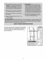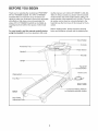
1
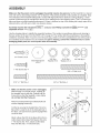
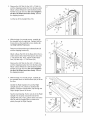
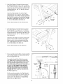
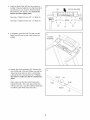
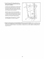
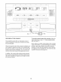
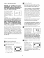
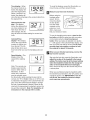
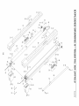
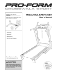
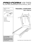
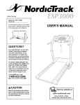
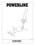
rain r
ModeJ No. 831.24745.0
SeriaJ No.
TR
LL EXERCIS
User's lVlanual
Number
Decal
, AssembJy
* Operation
* Maintenance
, Part List and Drawing
Sears, Roebuck and Co., Hoffman Estates, IL 60179
rain r
TABLE OF CONTENTS
iMPORTANT PRECAUTIONS
................................................................
BEFORE YOU BEGIN ......................................................................
ASSEMBLY ...............................................................................
OPERATION AND ADJUSTMENT ............................................................
HOW TO FOLD AND MOVE THE TREADMILL ..................................................
TROUBLESHOOTING
.....................................................................
CONDiTiONiNG GUiDELiNES ...............................................................
PART LiST ..............................................................................
EXPLODED DRAWING ....................................................................
ONE YEAR FULL WARRANTY .......................................................
3
5
6
11
18
19
22
23
24
Back Cover
iMPORTANT PRECAUTIONS
The decals shown below have been placed on the treadmill.
if a decal is missing, or if it is not legible, call toil-free 1-888533-1333 and order a free replacement decal. Apply the
decal in the location shown. Note: The decals may not be
shown at actual size.
)thers I[om risk ol serious
KEEPHANDS
ANDFEETAWAY
FROMTHiSAREA
WHILE
THE
TREADMILL
ISINOPERATION.
4
BEFORE YOU BEGIN
Thank you for selecting the revolutionary PROFORM ®
XP 615 TRAINER treadmill. The XP 615 TRAINER
treadmill offers an impressive array of features designed to make your workouts at home more enjoyable
and effective. And when you're not exercising, the
unique XP 615 TRAINER treadmill can be folded up,
requiring less than half the floor space of other treadmills.
For your benefit, read this manual carefully before
using the treadmill. If you have questions after read-
ing this manual, call 1-800-4-MY-HOME ®(1-800-4694663).To help us assist you, please note the product
model number and serial number before calling. The
model number of the treadmill is 831.24745.0. The serial number can be found on a decal attached to the
treadmill (see the front cover of this manual for the location).
Before reading further, please review the drawing
below and familiarize yourself with the labeled parts.
Book Holder
Console
Accessory Tray
Pulse Sensor
Handrail
Key/Clip
Upright
Reset/Off
Breaker
Power Cord
Walking Belt
Foot Rail
RIGHT SIDE
BACK
Rear Roller
Adjustment Bolts
Cushioned Walking Platform
for maximum exercise comfort
ASSEMBLY
Make sure that the power cord is unplugged. Assembly requires two persons. Set the treadmill in a cleared
area and remove all packing materials. Do not dispose of the packing materials until assembly is completed. Note:
The underside of the treadmill walking belt is coated with high-performance lubricant. During shipping, a small
amount of lubricant may be transferred to the top of the walking belt or the shipping carton. This is a normal condition and does not affect treadmill performance, if there is lubricant on top of the walking belt, simply wipe off the
lubricant with a soft cloth and a mild, non-abrasive cleaner.
E
Assembly requires the included he× keys
adjustable
_ and your own Phillips
screwdriver(_
======_ and
wrench _.
Use the drawings below to identify the assembly hardware. The number in parentheses below each drawing is
the key number of the part, from the PART LiST on page 23. The number after the parentheses is the quantity
needed for assembly. Note: if a part is not in the parts bag, check to see if it is preattached to one of the parts to
be assembled. Extra hardware may be included. If a part is missing, call toll-free 1-888=533=1333. To avoid
damaging plastic parts, do not use power tools for assembly.
3/4" Screw (10)-5
Base Pad Spacer
(25)-2
3/8" Star
Washer (9)-4
5/16" Star
Washer (7)-4
1" Tek Screw (56)-4
5/16" x 1" Bolt (5)-4
3/8" x 4" Bolt (6)-4
Make sure that the power cord is unplugged.
With the help of a second person, carefully tip
the treadmill onto its left side. Partially fold the
Frame (53) so that the treadmill is more stable;
do not fully fold the Frame yet.
Remove and discard the two indicated bolts (A)
and the shipping bracket (B).
Cut the tie securing the Upright Wire (78) to the
Base (80). Locate the tie in the indicated hole in
the Base, and use the tie to pull the Upright Wire
out of the hole.
Attach a Base Pad (79) to the Base (80) in the location shown with a Base Pad Spacer (25) and a
1" Tek Screw (56). Then, attach another Base
Pad (79) with only a 1" Tek Screw (56).
80
4t
53
79
56
3/8" Nut (8)-2
2. Removethe3/8"Nut(8),the3/8"x 2"Bolt(4),
andtheshippingbracket(C)fromthe Base(80).
Attacha BaseWheel(81)withtheBoltandthe
Nutthatyoujust removed.
Donot overtighten
the Nut;theWheelmustturn freely.Discard
theshippingbracket.
2
80
Cutthetie offthe UprightWire(78).
81
8
Withthehelpofa secondperson,carefullytip
thetreadmillontoitsrightside.Partiallyfoldthe
Frame(53)so thetreadmillis morestable;do
not fully fold the Frameyet.
B
Removeanddiscardthetwoindicated
bolts(A)
andtheshippingbracket(B).
Attacha BasePad(79)totheBase(80)inthelocationshownwitha BasePadSpacer(25)anda
1"TekScrew(56).Then,attachanotherBase
Pad(79)withonlya 1"TekScrew(56).
80
79_
53
56
Removethe3/8"Nut(8),the3/8"x 2"Bolt(4),
andtheshippingbracket(C)fromthe Base(80).
Attacha BaseWheel(81)withtheBoltandthe
Nutthatyoujust removed.
Donot overtighten
the Nut;theWheelmustturn freely.Discard
theshippingbracket.
56 79
8
I
With the help of a second person, carefully tip
the treadmill down so that the Base (80) is flat on
the floor.
Hentify the Right Upright (72) and the Right
Upright Spacer (74), which are marked with
stickers. Insert the Upright Wire (78) through the
Right Upright Spacer as shown.
See the inset drawing. Tie the wire tie in the Right
Upright (72) securely around the end of the
Upright Wire (78). Then, pull the other end of the
wire tie until the Upright Wire is routed completely through the Right Upright.
78
Wire
8O
74
Hole
5. Holda BoltSpacer(3)insidethelowerendof
theRightUpright(72).Inserta 3/8"x 4"Bolt(6)
witha 3/8"StarWasher(9)intotheRightUpright
andthe BoltSpacer.Repeatthisstepwitha secondBoltSpacer(3),3/8"x 4"Bolt(6),and3/8"
StarWasher(9).
5
80
OrienttheRightUpright(72)andtheRight
UprightSpacer(74)as shown.HoldtheRight
UprightSpacerandtheRightUprightagainstthe
Base(80).Becareful not to pinch the Upright
Wire (78). Finger tighten the two 3/8" x 4" Bolts
(6); do not fully tighten the Bolts yet.
Rounded
Corner
Press a Base Endcap (75) into the Base (80).
Hold a Bolt Spacer (3) inside the lower end of
the Left Upright (71). Insert a 3/8" x 4" Bolt (6)
with a 3/8" Star Washer (9) into the Left Upright
and the Bolt Spacer. Repeat this step with a second Bolt Spacer (3), 3/8" x 4" Bolt (6), and 3/8"
Star Washer (9).
Orient the Left Upright (71) and the Left Upright
Spacer (74) as shown. Hold the Left Upright
Spacer and the Left Upright against the Base
(80). Finger tighten the two 3/8" x 4" Bolts (6);
do not fully tighten the Bolts yet.
8O
Press a Base Endcap (75) into Base (80).
73
Have a second person hold the console assembly
near the Right Upright (72). Remove the wire tie
from the Upright Wire (78).
Connect the Upright Wire (78) to the console
wire. Make sure to connect the connectors
properly (see the inset drawing). The connectors should slide together easily and snap
into place. If they do not, turn one connector and
try again. IF THE CONNECTORS ARE NOT
CONNECTED PROPERLY, THE CONSOLE
MAY BE DAMAGED WHEN THE POWER IS
TURNED ON. Then, insert the connectors into
the Right Upright (72).
Console
Assembly
Set the console assembly on the Right Upright
(72) and the Left Upright (not shown). Attach the
console assembly with four 5/16" x 1" Bolts (5)
and four 5/16" Star Washers (7); start all four
Bolts and then tighten them.
Wi re
8
8. Insert the Book Rack (84) into the console assembly; it may be helpful to rock the Book Rack
up and down as you insert it. Attach the Book
Rack with five 3/4" Screws (10); start all five
Screws and then tighten them.
8
See step 6. Tighten the two 3/8" x 4" Bolts (6).
See step 5. Tighten the two 3/8" x 4" Bolts (6).
J
10
If necessary, press the Left Tray (86) and the
Right Tray (85) into the top of the console assembly.
10
10
9
Console
86
Assembly
10. Identify the Latch Assembly (55). Remove the
tie from the end of the tube. Make sure that the
sleeve has been slid over hole 1 and that the
10
Latch Knob (54) is locked into hole 1. Pull on
the sleeve to make sure that it is locked into
Hole 2
place.
Next, make sure that the Latch Knob (54) is
locked into hole 2. If it is not, pull out the tube
until you see hole 2 and then slide the tube back
in until the Latch Knob locks into hole 2.
54
Hole 1
Tube
Sleeve
55
11.RaisetheFrame(53)tothepositionshown.
Havea second person hold the Frame until
11
53
this step is completed.
Orient the Latch Assembly (55) so that the large
barrel and the Latch Knob (54) are in the positions shown. Attach the lower end of the Latch
Assembly to the bracket on the Base (80) with a
3/8" x 2" Bolt (4) and a 3/8" Nut (8).
Attach the upper end of the Latch Assembly
(55) to the bracket on the Frame (53) with a 3/8"
x 2" Bolt (4) and a 3/8" Nut (8). Note: It may be
necessary to move the Frame back and forth to
align the Latch Assembly with the bracket.
Lower the Frame (53) (see HOW TO LOWER
THE TREADMILL FOR USE on page 18).
12. Make sure that all parts are properly tightened before you use the treadmill. If there are sheets of clear
plastic on the treadmill decals, remove the plastic. To protect the floor or carpet, place a mat under the treadmill. Keep the included hex keys in a secure place; the large hex key is used to adjust the walking belt (see
pages 20 and 21 ).
10
OPERATION AND ADJUSTMENT
THE PRE-LUBRICATED
WALKING BELT
tric shock. This product is equipped with a cord having
an equipment-grounding conductor and a grounding
plug. Plug the power cord into a surge suppressor,
and plug the surge suppressor into an appropriate
outlet that is properly installed and grounded in
accordance with all local codes and ordinances.
Important: The treadmill is not compatible with
GFCl-equipped outlets.
Your treadmill features a walking belt coated with highperformance lubricant, iMPORTANT: Never apply silicone spray or other substances to the walking
belt or the walking platform. Such substances will
deteriorate the walking belt and cause excessive
wear.
HOW TO PLUG IN THE POWER CORD
This product is for use on a nominal 120-volt circuit,
and has a grounding plug that looks like the plug illustrated in drawing 1 below. A temporary adapter that
looks like the adapter illustrated in drawing 2 may be
used to connect the surge suppressor to a 2-pole
receptacle as shown in drawing 2 if a properly
grounded outlet is not available.
I
_-1
Your treadmill, like any other type of sophisticated
electronic equipment, can be seriously damaged by
sudden voltage changes in your home's power.
Voltage surges, spikes, and noise interference can
result from weather conditions or from other appliances
being turned on or off. To decrease the possibility of
your treadmill being damaged, always use a surge
suppressor with your treadmill (see drawing 1 at
the right). To purchase a surge suppressor, see
your local Sears store or call the toll-free telephone
number on the back cover of this manual and order
Grounded Outlet Box
_
Surge Suppressor
_w_" _.
Grounding Pin
Grounding P__.
_rounded Outlet
Grounding Plug"_
2
_rounded Outlet Box
Adapter
Surge Suppressor
part number 146148, or see your local electronics
store.
Use only a single-outlet surge suppressor that is
UL 1449 listed as a transient voltage surge suppressor (TVSS). The surge suppressor must have a
UL suppressed voltage rating of 400 volts or less
and a minimum surge dissipation of 450 joules.
The surge suppressor must be electrically rated for
120 volts AC and 15 amps. There must be a monitoring light on the surge suppressor to indicate
whether it is functioning
properly. Failure to use a
properly functioning surge suppressor could result
in damage to the control system of the treadmill, if
the control system is damaged, the walking belt
may change speed, accelerate, or stop unexpectedly, which may result in a fall and serious injury.
The temporary adapter should be used only until a
properly grounded outlet (drawing 1) can be installed
by a qualified electrician.
This product must be grounded. If it should malfunction or break down, grounding provides a path of least
resistance for electric current to reduce the risk of elec-
grounded
The green-colored rigid ear, lug, or the like extending
from the adapter must be connected to a permanent
ground such as a properly grounded outlet box cover.
Whenever the adapter is used it must be held in place
by a metal screw. Some 2-pole receptacle outlet box
covers are not grounded. Contact a qualified electrician to determine if the outlet box cover is
11
before using an adapter.
"_
_B_
E"-"-'
3.2J}I
I _'E
LI
I LI
TIME
DISTANCE
CALORIES
SPEED
WORKOUTS
WEIGHT
WORKOUTS
LOSS
25r) Cals, Walk FIs
2_
3_
,,*"
350Cals,
WelkCirr
"'7
b
_'_8
_3,0 Cal_, J,_j q
4_
f
•£,ELEOT
WORKOUT
_,.
TIME
'_
SET
MIN
SPEED
_F
_
450 Cals, Jog
9
lat
_tO
GO
SE T MAX
SpEE
D
J
INCLINE
FEATURES OF THE CONSOLE
To use the manual mode of the console, follow the
steps beginning on page t 3. To use a preset work=
out, see page 15.
The treadmill console offers an impressive array of
features designed to make your workouts more effective and enjoyable.
Note: If there is a sheet of clear plastic on the console,
remove the plastic. To prevent damage to the walking
platform, wear clean athletic shoes while using the
treadmill. The first time the treadmill is used, observe
the alignment of the walking belt, and center the walking belt if necessary (see page 20).
When the manual mode of the console is selected, you
can change the speed and incline of the treadmill with
the touch of a button. As you exercise, the console will
display instant exercise feedback. You can even measure your heart rate using the handgrip pulse sensor.
In addition, the console offers twelve preset workouts.
Each workout automatically controls the speed and incline of the treadmill as it guides you through an effective exercise session.
12
HOWTO
Start the walking
TURN ON THEPOWER
To start the walking belt, press the Start button,
the Go button, the speed increase button, or one
of the speed buttons numbered 2 through 10.
iMPORTANT: if the treadmill has been exposed to
cold temperatures, allow it to warm to room temperature before turning on the power. If you do not
do this, the console displays or other electrical
components may become damaged.
Plug in the power cord (see
page 11 ). Next, locate the
reset/off circuit breaker on
the treadmill frame near the
power cord. Switch the circuit breaker to the reset position.
belt.
If the Start button, the Go button, or the speed increase button is pressed, the walking belt will
begin to move at 1 mph. As you exercise, change
the speed of the walking belt as desired by pressing the speed increase and decrease buttons.
Each time a button is pressed, the speed setting
will change by 0.1 mph; if a button is held down,
the speed setting will change in increments of 0.5
mph. Note: After the buttons are pressed, it may
take a moment for the walking belt to reach the selected speed setting.
Position
Reset
iMPORTANT: The console features a display demo
mode, designed to be used if the treadmill is dis=
played in a store. If the displays light as soon as
you plug in the power cord and switch the circuit
breaker to the reset position, the demo mode is
turned on. To turn off the demo mode, hold down
the Stop button for a few seconds, if the displays
remain lit, see THE iNFORMATiON MODE on page
17 to turn off the demo mode.
If one of the numbered speed buttons is pressed,
the walking belt will gradually increase in speed
until it reaches the selected speed setting.
To stop the walking belt, press the Stop button. To
start the walking belt, press the Start button, the
Go button, the speed increase button, or one of
the speed buttons numbered 2 through 10.
Next, stand on the foot rails of the treadmill. Find the
clip attached to the key (see the drawing on page 12)
and slide the clip onto the waistband of your clothes.
Then, insert the key into the console. After a moment,
the displays will light, iMPORTANT: in an emergency
situation, the key can be pulled from the console,
causing the walking belt to slow to a stop. Test the
clip by carefully taking a few steps backward; if the
key is not pulled from the console, adjust the position of the clip.
Change the incline of the treadmill
as desired.
To change the incline of
the treadmill, press the
Incline increase and decrease buttons or one of
DISTANOE
the numbered incline
buttons. Each time the
incline increase or decrease button is pressed, the
incline will change by 0.5%. If one of the numbered incline buttons is pressed, the treadmill will
adjust to the selected incline setting. Note: After
the buttons are pressed, it may take a moment for
the treadmill to reach the selected incline setting.
ssl
HOW TO USE THE MANUAL MODE
Monitor your progress with the matrix and the
displays.
insert the key into the console.
The matrix--When
the
manual mode is sem
lected, the matrix will
--_/ll!lmmm
!
m
display a 1/4-mile track.
As you exercise, the indicators around the track
will light in succession
until the entire track is lit. The track will then
See HOW TO TURN ON THE POWER above.
Select the manual mode.
When the key is inserted, the manual
mode will be selected
and a track will appear
in the matrix. If a preset
workout has been
selected, remove the
key and then reinsert it.
m
_
darken and the indicators will again begin to light
in succession.
13
....
j
Time display--When
the manual mode is selected, this display will
show the elapsed time.
When a workout is se-
To reset the displays, press the Stop button, remove the key, and then reinsert the key.
rl
Measure your heart rate if desired.
TIME
lected, the display will
show the time remaining in the workout rather than
the elapsed time.
Distance/Incline
Before using the
handgrip pulse
sensor, first remove the sheets
of clear plastic
from the metal
contacts on the
pulse bar. In addition, make sure
that your hands are clean.
dis-
play--This display
shows the distance that
I "Z_l"Z_I
you have walked or run.
DISTANCE
Note: Each time the incline changes, the display will show the incline setting for several seconds.
To use the handgrip pulse sensor, stand on the
foot rails and hold the pulse bar with your palms
on the metal contacts. Avoid moving your
hands. When your pulse is detected, two dashes
(--) will appear in the Calories/Pulse display, and
then your heart rate will be shown. For the most
accurate heart rate reading, continue to hold
the contacts for about 15 seconds.
Calories/Pulse
display--This
display
shows the approximate
number of calories you
have burned. The dis-
C! rl.
C!
-J
""m]
I
CALORIES
play will also show your
heart rate when you use the handgdp pulse sensor.
When you are finished
key from the console.
Speed display--This
display shows the
speed of the walking
belt.
exercising,
remove the
Step onto the foot rails, press the Stop button, and
adjust the incline of the treadmill to the lowest
setting. The incline must be at the lowest setting
when the treadmill is folded into the storage position or the treadmill will become damaged.
Next, remove the key from the console and put it in
a secure place.
SPEED
Note: The console can
display speed and distance in either miles or
kilometers. To find
which unit of measurement is selected, press
the Stop button while inserting the key into the
console. An "E" for English miles or an "M" for metric kilometers will appear in the Calories/Pulse display. Press the speed increase button to change
the unit of measurement if desired. When the desired unit of measurement is selected, remove the
key and then reinsert it. Note: For simplicity, all
instructions in this manual refer to miles.
When you are finished using the treadmill, switch
the reset/off circuit breaker to the "off" position and
unplug the power cord. iMPORTANT: if you do
not do this, the treadmill's electrical components may wear prematurely.
14
HOWTO
The speed settings for the next two segments are
shown in the columns to the right.
USE A PRESET WORKOUT
insert the key into the console.
When only three seconds remain in the first segment of the workout, both the Current Segment
column and the column to the right will flash and a
series of tones will sound. If the speed and/or incline of the treadmill is about to change, the Speed
display and/or the Distance/Incline display will
flash to alert you. When the first segment ends, a//
speed settings
will
move one column tothe/eft.
The speed setting for the second segment will then
be shown in the flashing Current Segment column
and the treadmill will automatically adjust to the
speed and incline settings for the second segment.
Note: If all of the indicators in the Current Segment
column are lit after the speed settings have moved
to the left, the speed seLtings may move downward
so that only the highest indicators appear in the
matrix. If some of the indicators in the Current
See HOW TO TURN ON THE POWER on
page 13.
Select a preset workout.
To select a preset workout, press the Select
Workout button repeatedly.
When a preset workout
is selected, the minimum speed setting of
the workout will appear
in the Distance/Incline
nZ
mlmB
BBmlm
display, the maximum
speed setting will appear in the Calories/Pulse display, and the workout
time will appear in the Time display. In addition, a
profile of the speed settings of the workout will
scroll across the matrix.
Customize
your workout
Segment column are not lit when the speed settings move to the left again, the speed settings will
move back up.
The workout will continue in this way until the
speed setting for the last segment is shown in the
Current Segment column and the last segment
ends. The walking belt will then slow to a stop.
if desired.
You can change the length of the workout, the
minimum speed setting of the workout, and/or the
maximum speed setting of the workout before you
begin. To customize your workout, press the Set
Time, the Set Min Speed, and/or the Set Max
Speed increase and decrease buttons. The new
workout settings will appear in the displays.
If the speed or incline setting is too high or too low
at any time during the workout, you can manually
override the setting by pressing the speed or incline buttons. Every few times a speed button is
pressed, an additional indicator will light or darken
in the Current Segment column. (If any of the
columns to the right of the Current Segment column have the same number of lit indicators as the
Press the Start button or the Go button to start
the workout.
Current Segment column, an additional indicator
may light or darken in those columns as well.)
Note: When the next segment of the workout
begins, the treadmill will automatically adjust
to the speed and incline settings for the next
segment.
A moment after the button is pressed, the treadmill will automatically adjust to the first speed and
incline settings of the workout. Hold the handrails
and begin walking.
Each workout is divided into 30 one-minute segments, unless you have changed the length of the
program (see step 3). One speed setting and one
incline setting are programmed for each segment.
Note: The same speed setting and/or incline setting may be programmed for two or more consecutive segments.
The speed setting for
the first segment will be
shown in the flashing
Current Segment column of the matrix. (The
incline settings are not
shown in the matrix.)
To stop the workout at any time, press the Stop
button. To restart the workout, press the Start button or the Go button. The walking belt will begin to
move at 1 mph. When the next segment of the
workout begins, the treadmill will automatically adjust to the speed and incline settings for the next
segment.
Current Segment
mllR _
IRJ
15
Monitor your progress with the matrix and the
displays.
When you are finished
key from the console.
See step 5 on pages 13 and 14.
See step 7 on page 14.
Measure your heart rate if desired.
See step 6 on page 14.
16
exercising, remove the
THE INFORMATION
MODE
The Time display will show
the total number of hours the
treadmill has been used.
The console features an information mode that keeps
track of the total distance that the walking belt has
moved and the total number of hours that the treadmill
has been used. The information mode also allows you
to switch the console from miles to kilometers. In addi-
Note: The console features a display demo mode, designed to be used if the treadmill is displayed in a
store. While the demo mode is turned on, the console
will function normally when you plug in the power cord
switch the circuit breaker to the reset position, and insert the key into the console. However, when you remove the key, the displays will remain lit, although the
buttons will not function. If the demo mode is turned on
a "d" will appear in the Speed display while the information mode is selected. To turn on or turn off the demo
mode, press the speed decrease button.
tion, the information mode allows you to turn on and
turn off the display demo mode.
To select the information mode, hold down the Stop
button while inserting the key into the console and then
release the Stop button. When the information mode is
selected, the following information will be shown:
An "E" for English miles or
an "M" for metric kilometers
U
will appear in the
Calories/Pulse display.
Press the speed increase
button to change the unit of
measurement if desired.
The Distance/Incline display
will show the total number of
miles (or kilometers) that the
walking belt has moved.
To exit the information mode, remove the key from the
console.
J
C
I
17
HOW TO FOLD AND MOVE THE TREADMILL
NOW TO FOLD THE TREADMILL
FOR STORAGE
Before folding the treadmill, adjust the incline to the
lowest position. If you do not do this, you may damage the
treadmill when you fold it. Remove the key and unplug the
power cord. CAUTION: You must be able to safely lift 45
pounds (20 kg) to raise, lower, or move the treadmill.
1. Hold the metal frame firmly in the location shown by
the arrow at the right. CAUTION: To decrease the pos=
sibility of injury, do not lift the frame by the plastic
foot rails. Make sure to bend your legs and keep your
back straight as you raise the frame. Raise the frame
about halfway to the vertical position.
2. Raise the frame until the latch knob locks into the storage
position. Make sure that the latch knob is locked in
the storage position.
To protect the floor or carpet from damage, place a
mat under the treadmill. Keep the treadmill out of di=
rect sunlight. Do not leave the treadmill in the stor=
age position in temperatures above 85 ° F (30 ° C).
Latch Knob
HOW TO MOVE THE TREADMILL
Frame
Before moving the treadmill, convert the treadmill to the storage position as described above. Make sure that the latch
knob is locked in the storage position.
1. Hold a handrail and the frame and place one foot against
one of the wheels.
2. Tilt the treadmill back until it rolls freely on the wheels.
Carefully move the treadmill to the desired location. Never
move the treadmill without tipping it back. To reduce
the risk of injury, use extreme caution while moving
the treadmill. Do not attempt to move the treadmill
over
an
uneven
surface.
Wheels
3. Place one foot against a wheel, and carefully lower the
treadmill until it is resting in the storage position.
HOW TO LOWER THE TREADMILL
FOR USE
1. Hold the upper end of the treadmill with your left hand. Pull the latch knob to the left and hold it. It may be necessary to push the frame forward as you pull the knob to the left. Pivot the frame downward and release the
latch knob.
2. Hold the metal frame firmly with both hands and lower it to the floor. CAUTION: Do not grip only the plastic
foot rails or drop the frame to the floor. Bend your legs and keep your back straight.
18
TROUBLESHOOTING
Most treadmill problems can be solved by following the simple steps below. Find the symptom that
applies, and follow the steps listed, if further assistance is needed, call the toll=free telephone number
listed on the back cover of this manual.
PROBLEM:
The power does not turn on
SOLUTION:
a. Make sure that the power cord is plugged into a surge suppressor, and that the surge suppressor
is plugged into a properly grounded outlet (see page 11 ). Use only a single-outlet surge suppressor that meets all of the specifications described on page 11. Important: The treadmill is not compatible with GFCI-equipped outlets.
b. After the power cord has been plugged in, make sure that the key is inserted into the console.
C,
Check the reset/off circuit breaker located on the
treadmill frame near the power cord. If the switch
protrudes as shown, the circuit breaker has
tripped. To reset the circuit breaker, wait for five
minutes and then press the switch back in.
Tripped
Reset
PROBLEM:
The power turns off during
use
SOLUTION:
a. Check the reset/off circuit breaker (see the drawing above). If the circuit breaker has tripped, wait
for five minutes and then press the switch back in.
b. Make sure that the power cord is plugged in. If the power cord is plugged in, unplug it, wait for
five minutes, and then plug it back in.
c. Remove the key from the console. Reinsert the key into the console.
d. If the treadmill still will not run, please see the back cover of this manual.
PROBLEM:
The incline of the treadmill
does not change correctly
SOLUTION: a. With the key in the console, press one of the Incline buttons. While the incline is changing, remove the key. After a few seconds, re-insert the key. The treadmill will automatically rise to the
maximum incline level and then return to the minimum level. This will recalibrate the incline system.
PROBLEM:
The displays
of the console do not function
properly
SOLUTION:
a. Remove the key from the console and UNPLUG
THE POWER CORD. Remove the three 3/4"
Screws (10) and carefully pivot the Hood (57) off.
19
10
Locate the Reed Switch (64) and the Magnet (42)
on the left side of the Pulley (43). Turn the Pulley
until the Magnet is aligned with the Reed Switch.
Make sure that the gap between the Magnet and
the Reed Switch is about 1/8". If necessary,
loosen the Reed Switch Screw (12), move the
Reed Switch slightly, and then retighten the Screw.
Reattach the Hood, and run the treadmill for a few
minutes to check for a correct speed reading.
- 42
64 j
_J
Top
View
z
_43
I
PROBLEM:
The console
SOLUTION:
a. The console features a display demo mode, designed to be used if the treadmill is displayed in a
store. If the displays remain lit when you remove the key, the demo mode is turned on. To turn off
the demo mode, hold down the Stop button for a few seconds. If the displays are still lit, see THE
INFORMATION MODE on page 17 to turn off the demo mode.
PROBLEM:
SOLUTION:
The walking
displays
1/8"12 f
remain lit when you remove the key from the console
belt slows when walked on
a. Use only a single-outlet surge suppressor that meets all of the specifications described on page 11.
b.
If the walking belt is overtightened, treadmill performance may decrease and the walking belt may become damaged. Remove the key and UNPLUG
THE POWER CORD. Using the hex key, turn both
rear roller bolts counterclockwise, 1/4 of a turn.
When the walking belt is properly tightened, you
should be able to lift each edge of the walking belt
2 to 3 inches off the walking platform. Be careful to
keep the walking belt centered. Then, plug in the
power cord, insert the key, and run the treadmill for
a few minutes. Repeat until the walking belt is properly tightened.
Rear Roller Bolts
c. If the walking belt still slows when walked on, see the back cover of this manual.
2O
PROBLEM:
The walking
belt is off=center or slips when walked on
SOLUTION:
a. If the walking belt is off-center, first remove the
key and UNPLUG THE POWER CORD. If the
walking belt has shifted to the left, use the hex
key to turn the left rear roller bolt clockwise 1/2 of a
turn; if the walking belt has shifted to the right,
turn the bolt counterclockwise 1/2 of a turn. Be
careful not to overtighten the walking belt. Then,
plug in the power cord, insert the key, and run the
treadmill for a few minutes. Repeat until the walking belt is centered.
b.
if the walking belt slips when walked on, first remove the key and UNPLUG THE POWER CORD.
Using the hex key, turn both rear roller bolts clockwise, 1/4 of a turn. When the walking belt is correctly tightened, you should be able to lift each side
of the walking belt 2 to 3 inches off the walking
platform. Be careful to keep the walking belt centered. Then, plug in the power cord, insert the key,
and carefully walk on the treadmill for a few minutes. Repeat until the walking belt is properly tightened.
21
CONDiTiONiNG
GUiDELiNES
begin to use stored faicaloriesfor
energy. If your goal
is to burn fat, adjust the speed and incline of the treadmill until your heart rate is near the lowest number in
your training zone.
For maximum fat burning, adjust the speed and incline
of the treadmill until your heart rate is near the middle
number in your training zone.
Aerobic Exercise
If your goal is to strengthen your cardiovascular system, your exercise must be "aerobic." Aerobic exercise
is activity that requires large amounts of oxygen for
prolonged periods of time. This increases the demand
on the heart to pump blood to the muscles, and on the
lungs to oxygenate the blood. For aerobic exercise,
adjust the speed and incline of the treadmill until your
heart rate is near the highest number in your training
zone.
The following guidelines will help you to plan your exercise program. For more detailed exercise information, obtain a reputable book or consult your physician.
EXERCISE iNTENSiTY
Whether your goal is to burn fat or to strengthen your
cardiovascular system, the key to achieving the
desired results is to exercise with the proper intensity.
The proper intensity level can be found by using your
heart rate as a guide. The chart below shows recommended heart rates for fat burning and aerobic exercise.
HEART
RATE TRAINING
165
155
145
140
130
125
115
MAX
145
138
130
125
118
110
103
125
120
115
110
105
95
90
20
30
40
50
60
70
80
FAT BURN
Age
GUIDELINES
Each workout should include the following three parts:
A Warm=up--Start each workout with 5 to 10 minutes
of stretching and light exercise. A proper warm-up increases your body temperature, heart rate and circulation in preparation for exercise.
ZONES
AEROBIC
FAT BURN
WORKOUT
Training Zone Exercise--After
warming up, increase
the intensity of your exercise until your pulse is in your
training zone for 20 to 60 minutes. (During the first few
weeks of your exercise program, do not keep your
pulse in your training zone for longer than 20 minutes.)
Breathe regularly and deeply as you exercise--never
hold your breath.
To find the proper heart rate for you, first find your age
near the bottom of the chart (ages are rounded off to
the nearest ten years). Next, find the three numbers
above your age. The three numbers define your "training zone." The lower two numbers are recommended
heart rates for fat burning; the higher number is the
recommended heart rate for aerobic exercise.
A Cool=down--Finish
each workout with 5 to 10 min-
utes of stretching to cool down. This will increase the
flexibility of your muscles and will help prevent postexercise problems.
EXERCISE FREQUENCY
Fat Burning
To maintain or improve your condition, complete three
workouts each week, with at least one day of rest between workouts. After a few months, you may complete up to five workouts each week if desired. The key
to success is to make exercise a regular and enjoyable
part of your everyday life.
To burn fat effectively, you must exercise at a relatively
low intensity level for a sustained period of time.
During the first few minutes of exercise, your body
uses easily accessible carbo/zydrale ca/ofiesfor energy. Only after the first few minutes does your body
22
PART LiST--Model
No. 831.24745.0
Ro4o7B
To locate the parts listed below, see the EXPLODED DRAWING on pages 24 to 27.
Key No. Qty.
1
2
3
4
5
6
7
8
9
10
11
12
13
14
15
16
17
18
19
20
21
22
23
24
25
26
27
28
29
30
31
32
33
34
35
36
37
38
39
40
41
42
43
44
45
46
47
48
49
50
3
9
2
3
4
4
4
6
4
24
2
1
2
2
2
2
1
1
2
7
8
2
2
1
2
4
2
2
1
4
3
2
4
3
4
2
1
2
2
2
2
1
1
1
1
1
1
1
2
1
51
52
53
54
1
1
1
1
Description
Key No. Qty.
1/2" Screw
3/4" Tek Screw
Bolt Spacer
3/8" x 2" Bolt
5/16"x 1" Bolt
3/8" x 4" Bolt
5/16" Star Washer
3/8" Nut
3/8" Star Washer
3/4" Screw
2" Screw
Reed Switch Screw
5/16" x 1 1/4" Bolt
5/16" x 3 5/8" Bolt
1" Lift Frame Bolt
Rear Roller Bolt
3/8" x 1 3/4" Bolt
3/8" x 1 1/2" Bolt
3/8" x 1" Bolt
1/2" Ground Screw
1 1/4" Screw
1/4" Motor Bolt
3/8" x 3/4" Bolt
3/8" x 4" Bolt
Base Pad Spacer
Belt Guide Screw
1/4" Flat Washer
1/4" Lock Washer
3/8" Star Washer
U-nut
3/8" Motor Pivot Nut
3/8" Motor Nut
5/16" Nut
Hood Clip
Isolator Fastener
ProShox Decal
Left Foot Rail
Isolator
Belt Guide
Frame Spacer
Front Roller Spacer
Magnet
Front Roller/Pulley
Motor Belt
Right Foot Rail
Walking Belt
Walking Platform
Rear Roller
Rear Roller Bracket
Left Rear Foot
55
56
57
58
59
60
61
62
63
64
65
66
67
68
69
70
71
72
73
74
75
76
77
78
79
80
81
82
83
84
85
86
87
88
89
90
91
92
93
94
95
96
97
#
#
#
#
#
#
1
4
1
1
1
1
1
1
1
1
1
1
1
1
1
1
1
1
1
1
2
2
1
1
4
1
2
1
7
1
1
1
1
1
1
1
1
1
1
1
1
1
3
1
1
1
1
1
1
Description
Latch Assembly
1" Tek Screw
Hood
Lift Frame Ground Wire
Drive Motor Bracket
Drive Motor
Lift Frame
Filter Wire
Rear Roller Ground Wire
Reed Switch
Reed Switch Clip
Belly Pan
Reset/Off Circuit Breaker
Power Cord Grommet
Power Cord
Controller
Left Upright
Right Upright
Left Upright Spacer
Right Upright Spacer
Base Endcap
Caution Decal
Incline Motor
Upright Wire
Base Pad
Base
Base Wheel
Releasable Tie
Cable Tie
Book Rack
Right Tray
Left Tray
Console
Key/Clip
Console Base
Console Ground
Console Back
Left Grip Bracket
Access Door
Right Grip Bracket
Latch Warning Decal
5/16" Hex Key
Lift Frame Wire Tie
8" Green Wire, F/Ring
10" Red Wire, M/F
8" Black Wire, M/F
10" Blue Wire, M/F
10" Blue Wire, 2F
User's Manual
#These parts are not illustrated
Specifications are subject to change without notice.
if a part is missing, call toll-free 1-888-533-1333.
Hex Key
Right Rear Foot
Frame
Latch Knob
23
!'1"i
21
X
"0
r-
0
44
m
37
o
o
o
39\
° o
°
o
o
o
° o
o
o
o
° o
o
45
95
47
m
i
o
o
Z
40
0
o
46
21--_
l
Oo°o
o
o
i
0
o
o
o
o
o
o
o
m
Z
49 \
28
0
m
Co
27
53
55
28
=
_2
54
b
16
ZO
o
o
'--4
O3
EXPLODED
DRAWING B--IVlodei
No. 831.24745.0
57
60
24
31
62
64
66
25
RO407B
EXPLODED
DRAWING C--lVlodei
No. 831.24745.0
6
6
73
76
8O
4
81
8
81
83
26
Ro4o7B
EXPLODED
DRAWING D--IVlodei
No. 831.24745.0
Ro4o7B
88
84
87
89
85
91
I0
9O
92
10
10
93
10
94
I0
I0
27
Your Home
For repair--in
your
home--of
all major brand appliances,
lawn and garden equipment,
® Registered Trademark / TMTrademark / SMService Mark of Sears Brands, LLC
® Marca Registrada / TMMarca de Fabrica / SMMarca de Servicio de Sears Brands, LLC
f
ONE YEAR FULL WARRANTY
If this Sears Treadmill Exerciser fails due to a defect in material or workmanship within 1 year of the date
of purchase, call 1-800-4-MY-HOME ®(1-800-469-4663) to arrange for free repair (or replacement if repair proves impossible). The incline motor is warranted for 1 year from the date of purchase; the drive
motor is warranted for 25 years from the date of purchase.
This warranty does not apply when the Treadmill Exerciser is used commercially or for rental purposes.
This warranty gives you specific legal rights, and you may also have other rights which vary from state to
state.
Sears, Roebuck
Part No. 251435 RO407B
and Co., Hoffman Estates, IL 60179
Printed in USA © 2007 ICON IP, Inc.