1
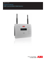
ABB solar inverters
Product manual
CDD (concentrator data device)
IMPORTANT SAFETY INSTRUCTIONS
This manual contains important safety instructions that must be followed during installation
and maintenance of the CDD.
It is required that the CDD be installed with any ABB MICRO inverter in compliance with
UL1741, for the purpose of indication and resetting of ground faults.
SAVE THESE INSTRUCTIONS!
Keep this document in a safe place near the inverter for easy access during installation and
maintenance.
THE INSTALLER MUST READ THIS DOCUMENT IN ITS ENTIRETY BEFORE
INSTALLING OR COMMISSIONING THIS EQUIPMENT.
This operating manual is a valid guide that will enable users to work safely, install the CDD
(concentrator data device) and carry out the operations necessary for keeping the equipment in
good working order.
Warranty conditions can be found on the product page of the website. NOTE: Any changes or
modifications not approved by the responsible party could void the user authority to operate
the equipment.
FCC REMARKS
The equipment has been tested and found to comply with the limits for a Class B digital
device, pursuant to Part 15 of the FCC Rules. These limits are designed to provide reasonable
protection against harmful interference in a residential installation. This equipment generates,
uses and can radiate radio frequency energy and, if not installed and used in accordance with
the instructions, may cause harmful interference to radio communications.
However, there is no guarantee that interference will not occur in a particular installation. If
this equipment does cause harmful interference to radio or television reception, which can be
determined by turning the equipment off and on, the user is encouraged to try to correct the
interference by one or more of the following measures:
001CV
• Reorient or relocate the receiving antenna.
• Increase the separation between the equipment and receiver.
• Connect the equipment into an outlet on a circuit different from that to which the receiver
is connected.
• Consult the dealer or an experienced radio/TV technician for help.
-2-
Product Manual
CDD - concentrator data device
1 - Introduction and safety
2 - Plan the installation
3 - CDD display operations
4 - Connect and configure the CDD
5 - Acquire the MICRO inverters
6 - System monitoring
7 - Appendix
001CV
CDD Product manual
BCG.00613.1_AA, NA Rev 1.0
© Copyright 2014 ABB. All Rights Reserved.
-3-
Contents
Introduction and safety....................................................................................................................... 7
Warnings in this document....................................................................................................................7
Intended use.............................................................................................................................................7
Available versions...................................................................................................................................8
Product label..........................................................................................................................8
Regulatory nameplate...........................................................................................................8
Plan the installation............................................................................................................................ 9
Description of the CDD...........................................................................................................................9
System integration................................................................................................................................10
Select the installation location.............................................................................................................11
Evaluate the installation position........................................................................................................12
Mount the CDD.......................................................................................................................................14
Connect and configure the CDD..................................................................................................... 15
Connect the CDD...................................................................................................................................15
Wireless connection to the internet....................................................................................................16
Open networks with a MAC address filter........................................................................16
Secure networks without a MAC address filter................................................................17
Secure networks with a MAC address filter.....................................................................17
Autoconnection configuration...........................................................................................17
DHCP configuration.............................................................................................................18
IP address view....................................................................................................................18
Ethernet connection to the internet....................................................................................................19
Firmware upgrade.................................................................................................................................20
CDD display operations................................................................................................................... 21
LED and display operations.................................................................................................................21
Description of the display menus........................................................................................................22
General Information cyclical display.................................................................................24
Basic information menu......................................................................................................24
Main menu - Statistics.........................................................................................................24
Main menu - View information............................................................................................25
Main menu - Change settings.............................................................................................25
Acquire the MICRO inverters.......................................................................................................... 27
002TC
Acquisition process .............................................................................................................................27
Acquire the MICRO inverters using the CDD display menu.............................................................27
Acquire the MICRO inverters using a computer and the integrated web server...........................28
-4-
System monitoring........................................................................................................................... 33
Remote monitoring on the Easy View web portal.............................................................................33
Self-registration procedure.................................................................................................33
Aurora vision plant viewer..................................................................................................35
Local monitoring using the CDD web server.....................................................................................36
HOME page...........................................................................................................................36
VIEW menu...........................................................................................................................37
CONFIG menu......................................................................................................................38
EVENTS menu......................................................................................................................40
UPGRADE menu..................................................................................................................40
REGISTRATION menu.........................................................................................................42
HELP menu...........................................................................................................................42
Appendix............................................................................................................................................ 43
002TC
The MICRO inverter system.................................................................................................................43
Characteristics of MICRO inverters...................................................................................43
Description of the CDD ......................................................................................................44
Alarm messages and codes.................................................................................................................44
Making a service call.............................................................................................................................49
Routine maintenance............................................................................................................................49
Technical data and types......................................................................................................................49
Wireless routers compatible with CDD...............................................................................................50
-5-
-6-
002TC
Introduction and safety
1
Warnings in this document
This is a list of special safety symbols used in this manual that highlight potential safety risks and/or useful
information. The symbol usage is described below:
CAUTION
The reader should stop, use caution and fully understand the operations
explained before proceeding.
DANGEROUS VOLTAGE
The MICRO inverter product works with high voltages. All work on the
inverter must follow the described documentation and must comply with all
prevailing codes and regulations associated with high voltages.
UL60950-1 Safety of Information Technology Equipment – General
Requirements: Part 1; CSA 60950-1-07 Safety of Information Technology
Equipment – General Requirements: Part 1
Intended use
This equipment is a device designed to configure and control a network of ABB MICRO inverters, using radio
communication and to supply data relating to the system, using a wireless connection or an Ethernet port, to
an internet or local portal for monitoring.
003CH1
• The device cannot be used in environments where there are particular restrictions on the use of radio
waves.
• The device used to transmit data to the ABB portal requires a user-supplied router connected to the internet.
The cost of connection is to be paid by the end user.
-7-
1- Introduction and safety
Available versions
The CDD described in this manual is available in a single version suitable for all countries of installation. It is
required that the CDD be installed with any MICRO inverter in compliance with UL1741, for the purpose of
indication and resetting of ground faults.
The device can be associated with the following MICRO inverter equipment from ABB:
0.25 kW models
MICRO-0.25-I-OUTD-US-208/240
MICRO-0.3-I-OUTD-US-208/240
0.3 kW models
MICRO-0.3HV-I-OUTD-US-208/240
Product label
The sample product label is affixed to the inverter and provides the following information:
CDD Part Number
CDD Serial Number
WIFI communication MAC address
Radio frequency communication MAC address
Ethernet MAC address
P/N: PPPPPPPPPPP
S/N: YYWWSSSSSS
MAC WIFI: A1:B1:C1:D1:E1:F1
MAC RF: A2:B2:C2:D2:E2:F2:G2:H2
MAC ETH: A3:B3:C3:D3:E3:F3
When registering the CDD on the Easy View portal, the MAC RF (radio frequency)
address is used as the product identification code (see System monitoring, Part 6).
Regulatory nameplate
The nameplate shown is affixed to the inverter and provides the following information:
®
Made in Italy
www.abb.com/solar
CONCENTRATOR DATA DEVICE
INPUT DC
MODEL:CDD
: 5V , 0.5 A
Technical data reported in this manual does not replace the data on the labels affixed
to the equipment.
-8-
004CC1
Contains FCC ID: X6W-EMBZ
Contains FCC ID: W70ZG2100-ZG2101
This device complies with Part 15 of the FCC Rules. Operation is subject to the
following two conditions: (i.) this device may not cause harmful interference and
(ii.) this device must accept any interference received, including interference
that may cause undesired operation.
Plan the installation
2
Description of the CDD
The ABB MICRO Inverters associated with the CDD can be monitored using the CDD display, the CDD web
server interface, or from the Aurora Vision monitoring portal.
The CDD display allows simultaneous monitoring of all the associated inverters. The following information can
be viewed by navigating in the display menu:
•
•
•
Operating status and statistics of each MICRO inverter
Operating status of the connection to the internet/local network
Alarm messages and fault indicators
The menus are navigated by means of buttons on the side of the CDD.
01
02
03
01
Wireless antenna
02
Status LED
(not on all models)
Radio antenna
(MICRO inverter)
03
150mm
5.90”
04
05
UP
DOWN
ESC
ENTER
06
005CH2
25mm
0.98”
07
08
180mm
7.08”
-9-
04
Display
05
Button pad
06
Ethernet port
07
Power connector
08
Ethernet communication status LED
2 - Plan the installation
System integration
The diagram below shows several MICRO inverters communicating with a CDD, which in turn connects, by
Ethernet or wireless, to a PC or a router connected to the internet. It is also possible to manage and monitor
the system using a PC or Smartphone with internet access by registering on the Aurora Vision Plant Viewer.
The CDD device must be configured in order to commission the PV system. The following configurations must
be completed on the CDD for proper operation of the system:
• Acquisition of MICRO inverters
• Setting geographical parameters
• Setting of grid standard for the country/region of installation.
These operations can be carried out using the CDD display or the Web Server integrated in the CDD. When
configuring using the Web Server it is necessary to connect the CDD to a PC via Ethernet or Wireless (see
configuration and connection details in part 4).
Once the configuration has been completed, the device can be registered on the Plant Viewer web portal using
an internet connection, which allows remote monitoring of the MICRO inverters making up the PV system.
Radio IEEE 802.15.4
Home Router
Ethernet or
802.11
Internet
CDD
Ethernet
Remote monitoring and settings
(internal web server)
802.11
Desktop
Laptop
Smartphone
Tablet
- 10 -
Ethernet or 802.11
Desktop
Laptop
006CC2
Local monitoring and settings
(internal web server)
2 - Plan the installation
Select the installation location
It is recommended to undertake connection, configuration and acquisition operations
before mounting the CDD in a permanent location.
During acquisition of the inverters in part 5, it can be determined if reception from the
inverters and from the wireless router is sufficient, or if the position or location should
be changed.
Consider the following before installing the MICRO/CDD system:
• Evaluate possible obstacles that can restrict or nullify the radio communication among MICROs and CDD.
• Analyze the communication quality considering the possibility of having to extend the radio antenna
externally (CDD Antenna Extension Cable).
• Each CDD has a capacity to monitor up to 30 MICRO inverters; for more than 30 MICRO inverters, it is
necessary to install more than one CDD.
• For wireless (WLess) connection with a router, make sure the router is available on the compatibility list
found in the appendix, part 7, and available online at www.abb.com/solarinverters.
• For Ethernet communication, there must be an unused Ethernet port on the router.
• For installations with multiple CDDs, it is recommended to acquire all MICRO inverters before mounting
them on the roof, using the “MICRO preinstallation kit” and related guidelines.
• Choose a place close to an electrical outlet where the bottom part of the device, (where connections are
present), remains accessible.
• Because the CDD uses radio waves to transmit and receive data, it is important to assess this factor in
choosing the installation position.
Walls in reinforced cement and surfaces covered in metal (doors, shutters, etc.) can markedly reduce the
reach of the device as noted below.
006CC2
Material
Open Field
Wood / Glass
Stone / Pressed cardboard
Reinforced concrete (reduction increases
with amount of reinforcement)
Metal
Relative signal range reductions
Approximately 100 m
0 – 10%
10 – 40%
10 – 90%
Up to 100%
The radio signal level between the CDD and MICRO inverter can be increased in several
ways as illustrated below:
- 11 -
2 - Plan the installation
Evaluate the installation position
The radio signal can be limited by obstacles and distance.
In order to boost the signal strength, position the antenna of the CDD in a parallel
line to the inverters. The antenna has a deadzone at the tip that should not be facing
the inverters.
CDD
When configuring the CDD and acquiring the
inverters in part 4 and 5, it may be necessary to
adjust the positioning of the antenna. The RF signal
quality is shown in the CDD display (see part 3).
Plant quality
High (65%)
An extension cable for the antenna can also be installed. The cable allows the antenna to be installed at a
distance from the CDD to go over or around possible obstacles to the radio signal.
The extended antenna can be installed in an outdoor rated plastic box (see technical note online “Improving
CDD Wireless Signal Reception” for detailed instructions), 15cm/6in above a roof and in line-of-sight of PV
panels. The extended antenna could also use the existing conduits of residential electrical systems or TV antennas to bring the CDD antenna outside.
Radio Antenna
15cm / 6in
Antenna ExtensionCable
Radio signal obstacle
006CC2
CDD
- 12 -
2 - Plan the installation
Before permanently mounting the system it is important to consider the possible scenarios shown
below and evaluate the right position for the CDD and MICRO inverters.
The distances used in the examples are between the CDD and the closest MICRO inverter available.
1
Wooden
2
Distance
less than
7.5m/25ft
Wooden
4
3
Wooden
?
Distance
less than
10m/33ft
Distance
more than
7.5m/25ft
?
Concrete
?
?
5
Evaluate the
RF signal
quality and
the possibility
to extend the
RF antenna
externally
6
Install the
antenna in
a plastic box
15cm/ 6in
above roof
and in lineof-sight of
PV panels
Metal or
reinforced
concrete
7
Distance
less than
30m/100ft
006CC2
Evaluate the
RF signal
quality and
the possibility
to extend the
RF antenna
externally or
to install the
CDD on the
top floor
Windows
- 13 -
Metal or
reinforced
concrete
2 - Plan the installation
Mount the CDD
It is recommended to undertake all the configuration operations in part 4 before
mounting the CDD in a permanent location. During acquisition of the inverters in part
5, it can be determined if reception from the inverters and router is sufficient, or if the
final position or location of the CDD should be changed.
Make the two holes necessary, using a drill with a 5 mm diameter bit.
The depth of the holes must be around 30 mm.
Insert plugs in the holes and tighten the countersunk screws supplied.
Fasten the CDD by putting the head of the screws in the two holes on the back.
006CC2
•
•
•
•
- 14 -
Connect and configure the CDD
Connect the CDD
4
In order to operate the system, the CDD must be plugged into an electrical outlet and connected to a computer
or router. The type of connection can be:
• Cabled - The CDD is equipped with an Ethernet port and can be directly connected to a PC or router. A
direct connection to a computer should only be used during configuration of the system to access the local
web server, not for regular monitoring. A cabled connection to a router can be used during configuration
and for data transmission to access CDD internal configuration pages (local web server).
• Wireless - The CDD is equipped with a wireless network card that can be connected to a router. This type
of connection can be used during configuration of the system to access the CDD internal configuration
pages (local web server) and for data transmission to the web portal in order to monitor the system.
The wireless connection of the CDD to the computer requires the use of a wireless router acting as a
“bridge” for the transmission of data. The configuration of the wireless network is done on the CDD display
using the panel buttons described below.
Turn on the CDD by attaching the power supply connector to the
bottom of the CDD and plugging into an electrical outlet; wait for the
green LED to come ON.
UP
DOWN
ESC
ENTER
The UP and DOWN buttons are used to move around inside a menu
or to scroll through a list of settable values.
The UP and DOWN buttons pushed together will open the three main
menus.
The ESC button returns the user to the previous submenu when
navigating.
007CH3
The ENTER button is pressed to make a selection or to confirm an
entered value/parameter.
- 15 -
4 - Connect and configure the CDD
Wireless connection to the internet
The wireless connection of the CDD is enabled by default and requires a router with IEEE 802.11b communication
protocol that will transmit the data to the web portal when there is an internet connection.
Requirements of the router:
• Compatibility with IEEE 802.11 communication protocol*
• Visible SSID
• WPA and WPA-2 security protocols supported.
* Check compatibility list in the appendix and on the website; a standard access point may be utilized to bridge
the CDD to an incompatible router.
The process of detecting WiFi networks within range begins as soon as the green LED is diplayed on the CDD.
• [XX] indicates number of networks found
• Open, WPA/WPA2 indicates type of protection; security protected networks require a security/passkey
• [00] indicates signal level/strength of connection, from 1-4 indicated by the number of characters
• Additional steps are required when connecting to networks with MAC address filters (see below).
The continuation of the installation differs depending on the type of protection of the selected network (Open,
WPA/WPA2). If no wireless networks are found, it may be necessary to change the DHCP settings, (page 24.)
Press ESC to exit
the menu
Installation
WiFi Scanning
WLess enabled
YES
More than one
network found?
NO
OPEN
Network?
Connecting to
WLess [XX]
YES
Connecting to
WLess [XX] Done!
NO
[
]
Scroll UP/DOWN to
view list of networks,
press ENTER to
select
Insert Passkey
ENTER passkey
and press ENTER
twice to connect
Open networks with a MAC address filter
The MAC address is used to set up the configuration menu of the router which is not supplied
by ABB. Refer to documentation from the manufacturer of the router for instructions to add
the CDD to the list of enabled MAC addresses on the router.
The MAC address can be found on the CDD product label as illustrated on page 8 and is
used to configure the router prior to connection. If the router has not been configured, the
MAC address will be displayed during the connection procedure as follows:
• The CDD will start the connection as shown above.
Connecting to
• The connection is refused and a Fail message is displayed. WLess [XX] Fail!
• The WiFi MAC address of the CDD is displayed.
MAC Address
Once the router is configured, power down the CDD to restart the A052725AF5222 >
configuration procedure outlined above.
- 16 -
008CC3
[XX]
Open
House ....
YES
>
4 - Connect and configure the CDD
Secure networks without a MAC address filter
A security key, or passkey, is required to access the a secure wireless network; enter the
passkey as follows:
• Press the UP or DOWN buttons to scroll the list of characters,
Insert Passkey
(0-9, A-F).
.........
• Press ENTER to confirm each character selected, (press
ESC to cancel the last character input).
• Press ENTER again to accept the passkey.
• Once the security key is input, press ENTER twice to start the connection attempt.
If the key is correct, a completion message appears on the display. If the key
input is not correct, the display shows the message “wrong password”; verify
the key and repeat the procedure.
Secure networks with a MAC address filter
• If a MAC address filter is present on the router, first enter the passkey as described above
in Secure networks without a MAC address filter.
• Once the passkey is entered correctly, it will be necessary to configure the MAC address
filter with the same procedure set out on the previous page for Open networks with a
MAC address filter (Open).
Autoconnection configuration
The CDD automatically memorizes the parameters of the last wireless connection made
(SSID and network key). The Autoconnect feature enables the CDD to automatically connect
to the last wireless network selected. To activate/deactivate the automatic connection function:
• Press any button from the GENERAL INFORMATION display (or press ESC if already in
a previous level of the BASIC menu).
• Scroll to WLess AutoConn in the BASIC menu.
WLess AutoConn.
• Press ENTER to select.
YES
>
• Scroll to YES/NO to activate/deactivate the function.
• Press ENTER to confirm the selection and ESC to return to the menu.
008CC3
If the last network that the CDD was configured for is not available, the CDD
will not connect to any network.
To configure the CDD for a new WLess network, disable the Autoconnection
feature and reboot the CDD. This will enable the CDD to search for available
wireless networks.
- 17 -
4 - Connect and configure the CDD
DHCP configuration
If no wireless networks are found, it may be necessary to change the DHCP settings. The
wireless setting must first be disabled.
Step 1 - Press any button to display the BASIC information menu relating to the CDD
• Press UP or DOWN until the WLess enabled YES screen is displayed.
• Press ENTER to remove the > (arrow) next to YES.
WLess enabled
• Press the UP or DOWN button to choose the option NO.
NO
• Press ENTER to confirm.
>
Step 2 – Press and hold the UP and DOWN buttons together in
Set Password
order access the MAIN MENUS; a password is required:
XXXX
• The first screen will display the message Set Password.
• Input the default password (0010) using the UP or DOWN buttons to change the number.
• Press ENTER to confirm each number; and press ENTER when complete (Use ESC to
return to the previous character).
Change
• After the password is entered, scroll DOWN to locate the Settings
>
Change Settings; menu and press ENTER.
• Scroll DOWN to the Network submenu.
Network
>
• Press ENTER, and scroll to DHCP Enabled. • Press ENTER, and choose to Enable or Disable the DHCP DHCP Enabled
NO
>
function (YES/NO).
• Press ENTER to confirm.
Step 3 - Re-Enable the wireless following Step 1 above.
• Press ENTER to remove the > (arrow) next to NO.
• Use the UP or DOWN button to choose the option YES.
• Press ENTER to confirm.
WLess enabled
NO
>
WLess enabled
YES
>
If the DHCP function is Disabled, it is necessary to set up the static IP network address
of the CDD to access the CDD Web Server for acquisition of the MICRO inverters in
part 4. Find the IP network address in the submenu Web Server IP show below.
IP address view
With the CDD connected to the network it is possible to view the IP address assigned to the
device.
• Press ESC to access the previous level of the BASIC menu
(or press any button from the GENERAL INFORMATION
display).
• Scroll to WebServer IP from the BASIC menu.
Web Server IP
.........
008CC3
The IP address that is displayed will be used in part 4, to access the CDD Web Server using
a computer or tablet.
- 18 -
4 - Connect and configure the CDD
Ethernet connection to the internet
WLess connectivity is enabled by default and will need to be disabled before connecting the Ethernet cable
using the following procedure:
• Press any button on the CDD from the GENERAL INFORMATION display to enter the BASIC menus.
• Scroll to WLess Enabled and press ENTER WLess enabled
• Use the UP and DOWN keys to change to NO and press ENTER.
NO
>
Once the wireless is disabled the CHANGE SETTINGS menu will be used to modify the Network settings.
• Press and hold the UP and DOWN buttons on the CDD display at the same time until the Set Password
screen is displayed.
• Using the UP or DOWN buttons, enter the password of 0010 by scrolling the Set Password
list of characters.
XXXX
• Press ENTER to confirm each character selected; press ESC to cancel the last
Change
character input.
Settings
>
• When the password has been entered, scroll to the CHANGE SETTINGS
menu and press ENTER.
Network
>
• Scroll to Network and press ENTER to select.
Select Network
• Scroll to select Select Network, WLess and press ENTER.
WLess
>
• Scroll to Ethernet and press ENTER to select.
• The CDD will automatically restart to reset the connection settings.
Select Network
Ethernet >
Connect the Ethernet cable if not already connected. Two possibilities for cabled
connection of the CDD to the computer are shown below.
The Ethernet port is located on the lower side of the CDD.
For either connection, be careful not to put the Ethernet cable in the RJ45 connector
for RS-485 serial communication.
1. Through a router using an Ethernet cable
This type of connection can be used both during configuration of the system to access the CDD internal
configuration pages (local web server) and for data transmission to the web portal in order to monitor the
system.
Router / Switch
CDD
008CC3
Ethernet cable
- 19 -
4 - Connect and configure the CDD
2. Direct to the computer using an Ethernet cable
This type of connection should only be used for configuration of the system to access the CDD internal
configuration pages (local web server)
CDD
Ethernet cable
If the computer is directly connected to the CDD without a router, and if the computer is set for
an automatic IP address, it is necessary to change the Network settings on the computer following the procedure below:
• Click on the internet icon in the computer system tray and open the Network and Sharing
Center
• Click Local Area Connection (LAN)
• Click Properties
• Click Internet Protocol Version 4 (TCP/IPv4)
• Click Get the following IP address and type a different IP Gateway address from that of the
CDD (e.g. if the CDD IP gateway address is 192.168.0.100, type 192.168.0.101) and click
OK
• The IP Gateway address of the CDD is shown on the display by pressing any button and
scrolling DOWN the basic list.
• Once these parameters are changed, input the IP Gateway address of the (CDD) in the
address bar of the Internet Browser to proceed with the acquisition of the plant.
• To reset the wireless connection on the computer, follow the steps in reverse order.
Firmware upgrade
It is recommended to upgrade the CDD firmware when connection to the internet is complete.
The firmware upgrade can be done in three different ways:
1. Firmware updgrade using the CDD display menu.
2. Firmware upgrade using the CDD web user interface (with either Ethernet or wireless
connection).
See System monitoring, part 6, for instructions to upgrade using method 1 or 2.
2. CDD Firmware update using Aurora Vision®
008CC3
A firmware update from Aurora Vision will be completed automatically following the procedure for selfregistration found in part 6.
- 20 -
CDD display operations
LED and display operations
3
The status of the inverter is indicated by the constant or intermittent lighting of the LED
located on the front of the CDD above the two line display. The display also shows a message
identifying the operation which is being carried out or the alarm/anomaly recorded.
(See Appendix, part 7 for description of alarm messages and error codes.)
The following table shows the possible combinations of LED activation relating to the operating state of the
CDD and MICRO inverters in the installation.
LED status
Operating state
FLASHING GREEN: No errors or alarms generated
STEADY GREEN:
FLASHING RED:
009CH4
STEADY RED:
Description
Installation of CDD and MICRO
inverters is operational.
Reporting of radio communication A transitional or permanent state
problems between MICRO
caused by the failure to receive
inverters and CDD or between
data by the CDD or by an absent
CDD and Router
or bad connection between the
CDD and the router.
Minor warnings:
Implies a small generation loss
that may be caused by power
Warning (message codes Wxxx) limiting or by causes external
Error (message codes Exxx)
to the MICRO inverter, such as
poor sunlight levels.
Major system warnings:
Reports a fault on one or multiple
MICRO inverters causing
Warning (message codes Wxxx) interruption to generation of
Error (message codes Exxx)
power.
- 21 -
4 - CDD display operations
Description of the display menus
The CDD display consists of 2 lines with 16 characters per line. The operating status and statistical data of the
inverter can be viewed along with service messages for the operator, warning and alarm messages. Inverter
settings can also be modified using the display menus.
• The UP and DOWN buttons are used to move around inside a menu or to scroll through a list of settable
values.
• The ESC button returns the user to the previous submenu when navigating.
• The ENTER button is pressed to select a submenu or to confirm an entered value/parameter.
• The UP and DOWN buttons pushed together will open the main menus for statistics, data display and
default settings.
An outline of the menu structure is shown below. A detailed description of the menu items can be found in the
table on page 14.
The thr
- Disp
- View
CDD
- Modi
Press any button during normal
operation for access to set up
and view the BASIC menu
options of the CDD
The CDD cycles through the
GENERAL INFORMATION
display during normal operation
Tot output power
.... W
Web Server IP
..........
Total Energy
.... KWh
MAC Addr. WLess
................
System quality
......
Subnet Mask
...........
MICRO: X
EXTRA: Y
IP Gateway
..........
Alarm status
......
Primary DNS
..........
DD/MM/YY
HH/MM/SS
Secondary DNS
..........
Network
......
WLess Enabled
Yes
>
WLess AutoConn.
Yes
>
Web Server
Reset Password?
WLess SSID:
......
Press and hold the UP/DOWN buttons on the CDD until
Set Password is displayed
Enter password 0010 to access three MAIN menus
- 22 -
010CC4
Press any button on the CDD
4 - CDD display operations
• Access the three MAIN menus fron the GENERAL INFORMATION display by pressing the UP and DOWN
buttons together until the Set Password screen is displayed on the CDD.
• Use the UP and DOWN buttons on the CDD to enter the default password 0010, pressing ENTER after
each entry.
The three MAIN menus are used to:
- Display statistics of the system and each inverter
- View a read only display of data related to the
CDD and the list of errors/warnings
- Modify CDD settings
during normal
ss to set up
ASIC menu
e CDD
Statistics
>
Tot output Power
....W
Total Energy
....kWh
Inverter data
>
View
Information
IP
..
PN
........
>
SN
..........
Less
.....
Firmware rel
>
sk
..
Date
DD/MM/YY
y
..
Time
HH:MM:SS
NS
..
Events
Alarm Present>
DNS
..
led
>
Change
Settins
Change Language
>
>
Set Date/Time
onn.
>
>
er
word?
D:
Set Time Zone
>
Display Timeout
>
Network
>
Reset
Ground Fault ?
until
Geo Position
>
s
Country STD
>
Remote update
010CC4
>
Micro Manager
>
- 23 -
4 - CDD display operations
GENERAL INFORMATION cyclical display
Total output power level of the MICRO Inverters that make up the plant
Total energy produced by the plant from the time it is put into operation
Plant quality expressed as a percentage and labeled Low, Medium, or High
MICRO: X = number of inverters in the plant
EXTRA: Y = number of inverters over limit of 30
Alarm status displays presence or absence of alarms, see section 7 for alarm codes
Date and time set on the CDD, use CHANGE SETTINGS menu to modify values
WLess strength of network connection, represented by 1 to 4
symbols
Press any button while in the GENERAL INFORMATION display to view the BASIC
information described below. Use the UP and DOWN buttons to scroll through the list.
BASIC information and options
Web Server IP address used to access the local web server of the CDD
MAC Addr. WLess address relating to the CDD
Subnet Mask address relating to internet
IP Gateway address used to send data of the monitored plant
Primary DNS primary address of internet domain name server
Secondary DNS secondary address of internet domain name server
Wless Enabled, Yes > wireless connectivity is enabled by default
Press ENTER to remove arrow >, press DOWN to scroll to NO, press
ENTER to select NO and disable wireless connectivity
Wless AutoConn., Yes > auto connection to last network connected is
recommended and enabled by default; press ENTER to remove arrow >,
press DOWN to scroll to NO, press ENTER to select NO and disable
Web Server, Reset Password? default password (admin) of the local web
server can be reset, press ENTER to reset , ENTER to confirm
Wless SSID: name of connected wireless network
To access the MAIN menus described below and continued on next page, press and hold
the UP and DOWN buttons until the Set Password screen appears; default password is 0010.
Scroll UP or DOWN to select a number and press ENTER to accept each digit.
MAIN menus
Statistics of the system and each inverter
Tot output power level of the inverters that make up the plant
Total Energy produced by the plant from the time it is put into operation
Inverter data > press ENTER to view
# microinverter displays the total number of inverters in the plant
SN xxxxxx > lists each inverter by serial number; scroll DOWN list
of inverters, press ENTER to select inverter and view following data:
Total Energy
eneral Information
Input Voltage
Output Power
cyclical display
DSP Release
Micro Release
asic information menu
Model ID
MAC Address
ain menu - Statistics
Output Current
Input Current
Output Voltage
Frequency
Temperature
G
View Information read only display
- 24 -and acquire inverters
Change Settings modify CDD settings
010CC4
B
M
4 - CDD display operations
MAIN menus
M
Statistics of the system and each inverter
ain menu - View
View Information read only display
PN of the CDD
information
SN of the CDD
Firmware Rel. > press ENTER to view
ain menu - Change
Application FW
settings
Bootloader FW
Wless Firmware
RF Firmware
Date
Time
Events, Alarms Present >
or NO alarms >press ENTER to view log of alarm codes listed by date
and time, identified as CDD or MIC (inverter) serial number
Change Settings modify CDD settings and acquire inverters
Change Language > of the CDD, press ENTER and select language from the list
Set Date/Time > of the CDD, press ENTER to change
Automatic: Yes scroll to NO and press ENTER to change
DST: NO scroll to YES to select daylight savings time if applicable
Enter date/time using UP/DOWN, press ENTER to accept change
Set Time Zone > of the CDD, press ENTER to change
Set Time Zone scroll UP/DOWN, press ENTER to select
GMT: +/- XX.XX scroll UP/DOWN, press ENTER to select
Display Timeout > press ENTER to change display timeout, 1 to 10 minutes or Off
Network, Change locked! Wireless network is enabled by default and locked.
To change to Ethernet, wireless must first be disabled from BASIC menu
Network > once wireless is disabled, press ENTER to change to Ethernet
Reset Ground Fault ?
Reset, Are you sure? press ENTER to reset
Geo Position > of the plant, press ENTER to change, use UP/DOWN to enter
latitude and longitude, press ENTER to accept change
Lat:/Long: N/S xx.xx, E/W xx.xx
Country STD > grid/country standard of the inverters, press ENTER and scroll
through the list of available grid standards, press ENTER to select
Remote update > press Enter to check for available updates
No Update Avail., Check Now? >
Check for update, waiting . . . . .
Micro Manager
[Add] Inverters > press ENTER to acquire inverters, GEO position and
timezone will display and always need to be entered for acquisition to start
Lat:/Long: > use UP/DOWN to enter coordinates, ENTER to accept
Set Timezone > use UP/DOWN to enter timezone, ENTER to accept
Scanning …. for inverters will begin after GEO position and timezone
are entered (see acquisition process in part 5)
[ST] Inverters > scroll DOWN list of inverters, press ENTER to view status
[Kll] Inverters > to remove individual inverters from the CDD, press DOWN
to scroll inverters identified by number, MAC and serial number
[03]MAC: XXXXXXXX, SN:XXXXXX press ENTER to select inverter
*** Kill > press ENTER to remove inverter from CDD
010CC4
M
- 25 -
010CC4
4 - CDD display operations
- 26 -
Acquire the MICRO inverters
5
Acquisition process
The acquisition of the MICRO Inverters by the CDD can be performed directly from the CDD display or with a
PC or Tablet connected via a Wireless network or Ethernet cable using the CDD “web user interface”.
In order to improve the acquisition process it is strongly recommended to pre-acquire all MICROs before
mounting them on the roof using the “MICRO Pre-installation Kit” and related guidelines (visit the website or
contact tech support to obtain information about this).
Acquire the MICRO inverters using the CDD display menu
Micro Manager
System coordinates* and time zone must be input (or confirmed if previously entered) before acquisition of>
the
MICRO inverters can begin. This step is will initiate the acquisition of the inverters.
Lat: N00.00
• From the GENERAL INFORMATION display, press and hold the UP and
DOWN buttons together until the
Long:E000.00
Set Password screen appears. Enter the default password (0010) to access the menus.
• Use the UP and DOWN buttons to navigate to the CHANGE
Micro
Manager
Set Timezone
SETTINGS menu.
>
GMT: +00.00
• Press ENTER and scroll to DOWN to Micro Manager >
• The MicroManager, [ADD] Inverter > screen opens.
Lat:
N00.00
Micro
Manager
• Press ENTER and the Lat/Long screen opens.
Long:E000.00
>
• Use the UP and DOWN keys to enter the latitude and longitude of [ADD]Inverters
the system*
• Press ENTER to confirm and the Set Timezone screen opens.
Set Timezone
Lat:
N00.00
• Use the UP and DOWN keys to select the applicable time zone.
GMT:
+00.00
>
Long:E000.00
• Press ENTER to confirm and the CDD will immediately begin
scanning for inverters to acquire.
Micro
Manager
Set Timezone
[ADD]Inverters
>
GMT: +00.00
011CH5
Micro Manager
[ADD]Inverters
>
*To determine latitude/longitude, go to Maps.Google.com
and enter an address. When
the map opens, right-click on the pointer and select “What’s here” from the dropdown
menu. Latitude/longitude will appear in the address bar and also under the green
arrow on the map. If a negative sign (-) is given, enter it along with Lat and/or Long.
- 27 -
Micro Manager
>
5 - Acquire
the MICRO
inverters
Scanning for inverters to acquire begins after the Geo position and Timezone have been entered as shown on
Micro Manager
the previous page.
[Add] Inverters
>
• Scanning displays number [XX] of inverters found.
• Press ENTER to Stop the acquisition process when the Scanning . . .
[XX}
Stop >
correct number of inverters [XX] are found.
The CDD will continue scanning and the process must be
manually stopped by the user.
• MAC of the first inverter [01] found will be displayed.
Signal strength for the specific inverter is shown as *; number
of stars indicates signal strength, four stars the maximum.
• Press DOWN to select and commit each inverter and move
to the next.
To delete (exclude) a single inverter press ENTER to select
Del > (instead of pressing DOWN to commit) and move to
the next inverter.
[01]MAC:A05725AF222
***
Del >
[02]MAC:A05527DA195
***
Del >
[03]MAC:215527AO2062
***
Del >
• When all scanned inverters have been selected or deleted,
the total number of acquired inverters is displayed. Press
Commit complete!
ENTER to confirm completion (OK>).
Total: [03]
• Country Standard screen opens and displays the first
grid/country standard in the list Press ENTER to remove the
arrow > and scroll DOWN the list of available country/grid
standards.
• Press ENTER to select the applicable standard to be passed
to the acquired inverters.
When complete, the CDD returns to the MicroManager [Add]
Inverters screen. Press ESC to exit the MAIN menus.
OK>
USA208V@60HzCSA
>
Micro Manager
[Add] Inverters
>
Acquire the MICRO inverters using a
computer and the integrated web server
Follow the steps below when the Home page of the web portal is displayed.
- 28 -
011CC5
On completing the connection and configuration phase in part 4, the CDD will be connected to
a computer. A browser with active Javascript must be used to view the Local Web Portal pages
properly. To access the local web portal, enter the IP address of the Web Portal (page 24) in
the URL address bar of a browser.
5 - Acquire the MICRO inverters
Select MicroManager
from the drop-down
CONFIG menu on the
Home page
Authentication is required
Enter the default access credentials
Username: admin - Password: admin
Press OK
011CC5
Click to view a drop
down list of timezones
Click confirm to
make changes
- 29 -
Use the drop-down list to
view grid/country standards
5 - Acquire the MICRO inverters
Click START ACQUISITION
to begin scanning
Inverters are identified
by MAC address (MACRF)
and/or serial number (SN)
There is no timeout for the acquisition
procedure. Click on STOP ACQUISITION
to manually terminate the procdure
once all the inverters are displayed.
011CC5
Use check box to
select inverters
for acquisition
Press CONFIRM
to complete
- 30 -
5 - Acquire the MICRO inverters
Select Country Standard
from the drop-down menu
Press CONFIRM
Select this link to register
the CDD on the web portal
Click here to complete the
acquisition and register later
• If the link to register the CDD has been selected (“CLICK HERE TO REGISTER....”), the registration
welcome page will open. The registration procedure is described in part 6, System monitoring.
• If the the registation has been bypassed until later, the Home page will be displayed. Click on HOME in
the menu to exit Micro Manager.
011CC5
• Upon successful completion of the configuration procedures, the CDD can be mounted to the wall as
described in section 2.
- 31 -
011CC5
5 - Acquire the MICRO inverters
- 32 -
System monitoring
6
Remote monitoring on the Easy View web portal
When the acquisition of the MICRO Inverters is complete, it is possible to configure the remote monitoring
of the plant on the Aurora Vision web portal using the self-registration procedure described below.
Self-registration procedure
To start the self-registration process go to https://register.auroravision.net/cdd?mac=AA:
BB:CC:DD:EE:FF:GG:II (The page will automatically open at the end of the acquisistion
process for the MICRO inverter when “CLICK HERE TO REGISTER YOUR CDD
XX:XX:XX:XX:XX:XX:XX:XX”) is selected.)
012C6
Read through the overview
to understand the steps
click Next to register
- 33 -
The registration process is completed in three steps:
Step 1.
• Enter personal contact information.
• Enter an email account.
• An email with a validation will be sent to
the registered account.
• Open the e-mail and click on the link to
continue the registration.
Account validation must occur within
3 days of receipt of the email; if not the
process will have to be re-started.
Step 2
• Enter details about the solar power site/
home.
• Provide the installer’s name and contact
information to help direct current and
future homeowners to the installer for any
future project and service needs.
• Site information defaults to the homeowner
address but can updated to a different
address for alternate locations such as a
second home.
012C6
Step 3
• Link and validate the CDD to the solar
power site.
• Make sure the CDD is connected to the
internet.
• Enter the CDD’s RF MAC address (MAC
RF) in the 8 display fields.
• Click on the Validate button.
• When validated, the logger and all
configured inverters will be displayed
• Click I’m Done to complete the registration
process.
• An e-mail will be sent confirming that
the registration has been successfully
completed.
- 34 -
Aurora vision plant viewer
Aurora Vision Plant Viewer is a free software that offers remote plant monitoring through the
internet.
The portal is divided 3 main sections:
The upper section contains general information about the system
In the middle is the graph of total production of energy for a period which can be set (from a
single day up to 365) and the output power of each MICRO inverter
On the bottom are the Environmental Benefits based on the total energy produced by the
plant.
012C6
In addition to monitoring, the portal offers automatic upgrade of the firmware installed in the
MICRO inverters and the CDD. When new firmware is available, an e-mail is sent to the
registered email address to alert the need for an upgrade.
- 35 -
6 - System monitoring
Local monitoring using the CDD web server
In order to access the CDD local web server, a PC or tablet must be connected to the same local network, i.e.
through the same Ethernet or Wireless router, or connected directly to the CDD using an Ethernet cable. Enter
the IP address (page 24) and wait until the Home page is displayed.
HOME page
The following information is displayed in the pop-up window:
MAC RF: Radio frequency MAC address
ALARM STAT: number of alarms on
individual inverter
INV STAT: allows 3 states, RUN (booster
TIME STAMP: Date and time of the display
generating power), START UP (inverter
awakening) and PROT (inverter into
Fw RF: Radio frequency firmware version
protection)
uP: inverter firmware version
VOUT: Output voltage
IDs:
IOUT: Output current
DSP: DSP firmware version
FREQ: Frequency
IDi:
VIN: Input voltage
PN: part number
POUT: Output power
MODEL DESC: inverter model
EN TOT: Total energy produced
SIGNAL: strength of radio communication
TEMP DSP: Internal DSP temperature
signal between the CDD and inverter
BOOST STAT: allows 3 states, RUN (booster TEMP MOSF: Mosfet temperature
operational), START UP (booster awakening)
and PROT (booster into protection)
- 36 -
012C6
Click on the serial number
to open a pop-up window
with individual inverter
information
6 - System monitoring
VIEW menu
View > Info: displays information for plant, system, date/time and network.
Use edit to
modify data
Use scroll bar to
view more data
View > RF Signal: Msg and Average plant signal index are refreshed every 15 minutes.
Average
signal strength
Messages received by
the CDD from each inverter
in the last 15 minutes*
RSSI “received signal strength
indicator”, a measurement of the
power present in a received radio
signal from the MICRO inverter
012C6
* Each MICRO Inverter sends a package of data to the CDD once a minute.
In order to accurately evaluate a CDD positioning, wait 15 minutes from the power-on
of the device.
- 37 -
6 - System monitoring
CONFIG menu
Selecting Config on the menu bar gives access to eight drop-down menus.
Config > Plant: used to modify plant information including plant and location name, address,
latitude, longitude, time zone, and country standard.
Click to view a drop
down list of timezones
Click confirm to
make changes
Use the drop-down list to
view grid/country standards
012C6
Config > Network: provides basic information of the connected network.
Config > Date/Time: used to adjust date and time.
Config > CDD clone: allows configuration of a new CDD with the same settings as a previous
CDD by using the last 4 pairs of digits of the old CDD’s MAC address.
- 38 -
6 - System monitoring
Config > CS param: modification of country standard
Config > Ground/Fault/Energy: options to reset ground fault and/or reset energy history for
statistical views
Config > Change Pass: use to change the default password (admin)
012C6
Enter default password
enter and retype new
password and click
Confirm to change
- 39 -
6 - System monitoring
EVENTS menu
A log of system events relating CDD and inverters is displayed in the Events menu. This
includes errors (Exxx) and alarms (Wxxx)codes; see Appendix, Part 5, for a complete
description of these events.
UPGRADE menu
The Upgrade menu can be used to upgrade firmware of the CDD and MICRO inverter and
load an updated country standard list.
CDD Remote Upgr.:
012C6
Updates must be enabled on
the Config > Network menu
to be available for upgrade
- 40 -
6 - System monitoring
CDD Local Upgr.:
The CDD firmware is available on the web site https://registration.ABBsolarinverters.com or
by contacting customer service. Download the files and save them on a computer to perform
a local updgrade. There will be two separate files for Ethernet and wireless firmwares.
Step 1
Load Ethernet firmware
Browse to location on computer
where firmware files have been
downloaded and saved
Open file and select Upload
Step 2
Load wireless firmware
Browse to location on computer
where firmware files have been
downloaded and saved
Open file and select Upload
Step 3 (final)
Reboot CDD
012C6
Select “click here” link to reboot CDD and
apply update, confirm firmware revision
from View > Info menu or the CDD display
- 41 -
6 - System monitoring
uP MICROinv Fw: used to update the microproccesor firmware of the CDD. The firmware
must first be downloaded and saved on a computer in order to browse and select the files for
upload, see CDD Local upgrade above.
CS Local Upgr.: used to load an updated list of available grid/country standards. The firmware
must first be downloaded and saved on a computer in order to browse and select the files for
upload, see CDD Local upgrade above.
REGISTRATION menu
This menu will launch the Aurora Vision welcome page. See Remote monitoring > Self
Registation on page 33 for instructions to complete the process.
HELP menu
012C6
Identified by a question mark ? on the menu bar, the help menu contains the address, email,
and telephone number of ABB customer service and technical support in various countries.
- 42 -
Appendix
7
The MICRO inverter system
This system is composed of a group of MICRO Inverters that convert direct electric current from a photovoltaic
module into alternating electric current and feed it into the utility grid.
Photovoltaic modules transform energy from the sun into direct current (DC) electrical energy (through a
photovoltaic field, also called photovoltaic module). In order to use it, it is necessary to transform the type of
current into alternating “AC”. This conversion, known as DC to AC inversion, is made efficiently without using
rotating parts and only through static electronic devices.
In order to allow inverter operation in safe thermal and electrical conditions, in the event of adverse environmental
conditions or unsuitable input voltage values, the unit automatically reduces the value of the power fed into the
grid. This way the solar energy system compensates for the energy drawn from the utilities connected to the
grid to which it is linked. The solar energy system then powers all connected electrical devices, from lighting to
household appliances, etc.
When the photovoltaic system is not supplying sufficient power, the power needed to ensure normal operation
of the connected electrical devices is drawn from the utility grid. If, on the other hand, excess power is produced,
this is fed directly into the grid, becoming available to other consumers.
In accordance with local and national regulations, the power produced can be sold to the grid or credited
towards future consumption. Each inverter will work independently of the others and will supply the grid with
the maximum power available from its photovoltaic panel.
Characteristics of MICRO inverters
Unlike systems subdivided into strings controlled by one or several inverters, systems of this
sort are built for the incorporation of a MICRO Inverter for each photovoltaic module.
013C7
Each MICRO Inverter works independently of the others, thus its own photovoltaic module
supplies the maximum power available to the grid. This setup enables a direct control over
the production of a single photovoltaic module, consequently optimizing production as much
as possible.
- 43 -
7 - Appendix
Description of the CDD
The Power-One MICRO Inverters associated with the CDD are monitored using CDD display,
the CDD web server interface, or from the Aurora Vision monitoring portal.
The display for the CDD permits simultaneous monitoring of the associated inverters. The
following information can be viewed by navigating in the menu:
• Operating status and statistics of each MICRO Inverter
• Operating status of the connection to the Internet/local network
• Alarm messages and fault indicators.
The display offers user friendly and intuitive use with the capability of navigating through the
various menus by means of buttons on the side of the CDD.
Alarm messages and codes
The MICRO Inverter is capable of communicating errors/warnings via radio to the associated CDD. The table
below provides a description of the alarm messages and error codes displayed on the CDD.
E004
blinking red
Vbulk OV
Cause
Solution
The error appears when the
inverter input current exceeds the
set overcurrent threshold. This
may be caused by:
a) sudden sunlight changes
that may generate input current
surges into the MICRO inverter
b) PV module incompatible with
the MICRO inverter input characteristics
c) Faulty MICRO inverter
The error is generated when the
voltage at the ends of the bulk
capacitors exceeds the Over
Voltage threshold. This may be
caused by:
a) Grid voltage too high
b) Internal inverter fault
a) The error occurs sporadically and
no action is required as the MICRO inverter will automatically reset to normal
operation
b) It is necessary to verify that the
photovoltaic module specifications are
compatible with the inverter.
c) If conditions a) and b) have been
verified and the error persists, the malfunction may be caused by an internal
inverter fault.
a) Check that the grid voltage is compatible with the MICRO inverter specifications. In the event of highly abnormal grid voltage, please contact your
grid operator to address the problem.
b) If no problems are found when
checking the grid voltage, the alarm
may be caused by internal inverter
faults.
013C7
Display code
LED status
Message
E001
blinking red
Input OC
- 44 -
7 - Appendix
Cause
Solution
The error appears when the inverter output current exceeds the
internal inverter alarm threshold.
This may be caused by:
a) High impedance grid with significant voltage variations, even
with small loads.
b) Internal inverter fault
E014
blinking
green
OverTemp
High internal temperature recorded by the inverter. This parameter
depends in part on the power that
the inverter must supply, as the
internal inverter temperature is
affected by the heat dissipated
internally by its components. This
may be caused by:
a) Failure to observe the installation conditions
b) Internal inverter fault
a) Check that the grid voltage is stable,
mainly upon:
- loading with high current peak loads.
- maximum power generation of the
PV system
If the grid voltage is unstable, verify
the appropriate sizing of the line
cable/s, and, if correct, please contact your grid operator to address the
problem.
b) If no problems are found when
checking the grid voltage, the alarm
may be caused by internal inverter
faults.
a) Verify the installation conditions
(exposure to sunlight) and check that
air flow to the MICRO inverter is not
obstructed, so as to permit cooling of
the device. Check that the ambient
temperature measured around the
MICRO inverter does not exceed the
limits set in the technical data.
b) Verify the MICRO inverter temperature readings (see the Internal Web
Server section in the CDD manual). If
one of the temperatures remains at a
value which is not compatible with the
environmental conditions (e.g. -40°C
internal temp. reading with 20°C effective ambient temperature), the alarm
may be due to internal inverter causes.
013C7
Display code
LED status
Message
E006
blinking red
Output OC
- 45 -
7 - Appendix
Display code
LED status
Message
E018
blinking
green
Ground fault
Cause
Solution
The error is generated when a
ground leakage current is detected in the DC section of the
system. This may be caused by:
a) PV module ground leakage
b) Internal inverter fault
See the “Verification of ground leakage” and “Measuring the insulation
resistance” sections for information on
how to perform checks and measurements.
a) If the measured insulation resistance value is less than 1KΩ, the PV
module has a ground leakage that
prevents the grid connection of the
inverter. In this case the PV module
must be replaced.
b) If the measured value exceeds
1KΩ, try connecting the MICRO inverter to a different PV module. If the error
persists, the alarm may be caused by
internal inverter faults. To perform this
test, the MICRO inverter Ground Fault
condition must be reset via the Web
Server.
a) Verify the grid parameters and, if
the grid voltage is strongly distorted,
please contact your grid operator to
address the problem
If the grid voltage is stable, the error
may also be due to sudden irradiance
variations. In this case, the inverter
will automatically try to reconnect to
the grid and no actions are required to
solve the problem.
b) If the grid voltage is stable, yet the
error systematically persists, the malfunction may be caused by an internal
inverter fault
The error is generated if the DC
component of the current supplied to the grid exceeds the
threshold set by the country of
installation’s applicable regulation. In any case, the inverter will
automatically try to reconnect to
the grid. This may be caused by:
a) Sporadic recurrence of this
error is a sign of large grid distortions or sudden changes in
irradiance.
b) Systematic recurrence of this
error may be due to an inverter
fault.
E024
a) The alarm may occur durBlinking red ing inverter initialization and is
Internal Error caused by the initialization of
communication between the CDD
and the MICRO inverters.
b) Systematic occurrence of this
error may be due to an inverter
fault.
a) The alarm will automatically reset
upon connection of the inverter to the
grid, and no actions are required to
solve the problem.
b) If the error systematically persists,
the malfunction may be caused by an
internal inverter fault
013C7
E023
Blinking
green
DC Injection
- 46 -
7 - Appendix
Cause
Solution
The set grid standard is not compatible with the firmware installed
on the MICRO inverter. This
condition may be generated if a
MICRO inverter is replaced.
E052
Solid red
Country
mismatch
The alarm is generated when the
grid standard (selected on the
CDD during installation) has not
been correctly set on the MICRO
inverters. This may be caused by:
a) communication problems while
setting the grid standard for the
MICRO inverter from the CDD:
b) poor irradiance while setting
the grid standard for the MICRO
inverter from the CDD: MICRO
inverters are directly supplied
by the voltage generated at the
panel, and poor irradiance may
cause inverter shut downs
E501
Blinking
green
Communication fault
The alarm is generated when
the CDD device does not receive
messages from the MICRO-inverter for more than 15 minutes.
This may be caused by non-optimal positioning of the CDD.
W001
Blinking
green
Vpanel Problem
This alarm is displayed when the
input voltage generated at the PV
generator is outside the allowed
range given in the technical data.
This may be caused by:
a) Poor sunlight
b) Possible shadows that may
darken the module during part of
the day.
b) PV module incompatible with
the MICRO inverter input parameters
d) Internal inverter fault
The firmware in the MICRO inverter/s
in the installation must be updated to a
compatible version. Firmware updates
are performed via the Internal Web
Server (see the CDD manual), with the
software package obtained from customer service.
a) Verify on the Internal Web Server
(as described in the CDD manual),
the radio communication quality on
each MICRO inverter (values above
60% indicate good reception). If the
quality of the received signal is good
re-configure the installation, otherwise
consider installing the CDD device in a
different position to ensure better radio
signal quality.
b) System configuration must be
carried out in good irradiance conditions, in order to guarantee the correct
operation of the MICRO inverter and to
prevent the risk of shut-downs due to
insufficient input voltage generated by
the PV module.
Consider a new installation position
that ensures better communication
between the CDD device and the MICRO-inverters. Use the CDD Internal
Web Server to verify the signal quality
(refer to the CDD manual for information on the Internal Web Server)
a) Wait for appropriate sunlight to
guarantee correct operation of the
inverter
b) Verify that no shadows are present
on the PV module when the error is
generated
c) Verify that the PV module voltage
characteristics are compatible with the
inverter input specifications.
d) If the above checks have yielded
positive results, yet the error persists,
the malfunction may be caused by the
MICRO inverter.
013C7
Display code
LED status
Message
E051
Solid red
Country Not
Comp
- 47 -
7 - Appendix
W004
Blinking
green
VAC OV
W005
Blinking
green
VAC UV
W011
Solid red
Vbulk UV
W032
Blinking
green
Pgrid limitation
W033
Blinking
green
Pgrid Fgrid
limitation
W034
Blinking
green
Pgrid VAC
high limitation
W035
Blinking
green
Cause
Solution
This alarm is generated when
one or more grid parameters lie
outside the permitted range set
by the country of installation’s
grid standard. The error code will
be followed by a suffix in brackets indicating the grid parameter
out of range:
(UV) Grid voltage below the set
lower limit
(OV) Grid voltage above the set
upper limit
(UF) Grid frequency below the
set lower limit
(OF) Grid frequency above the
set upper limit
Internal fault of the booster circuit
inverter
If the error is generated only on one of
the installation MICRO inverters, this
may be due to an inverter fault.
If the alarm is generated at multiple
inverters in the installation, check the
grid voltage for instabilities in any of
the 4 parameters monitored by the
inverter. If anomalous values are detected, verify the sizing of the AC line
conductors. In case of correct sizing,
please contact your grid operator to
address the problem.
Contact customer service.
MICRO is limiting AC power due If problem persists check grid connecto an external condition; not an
tion condition.
error but a certain working condition
MICRO is limiting AC power due
standard frequency regulation.
If problem persists check grid frequency condition.
MICRO is limiting AC power due
to a standard voltage regulation.
If problem persists check grid voltage
condition.
Fgrid problem
(UF) grid frequency below the set
lower limit
(OF) grid frequency above the upper
limit
013C7
Display code
LED status
Message
W003
Blinking
green
Grid Fail
- 48 -
7 - Appendix
Making a service call
Call technical support at 877-261-1374 and provide the following information to initiate a call:
• Model number
• Serial number
• Status of LED light(s)
• Steady or flashing
• Error message or code
Routine maintenance
The CDD has no user-serviceable part and needs no maintenance interventions.
Do not attempt to dismantle the equipment or make any internal repairs!. Any attempt to open
the equipment could comprise the integrity of the casing’s insulation and violate the integrity
of the NEMA 1 rating and/or create a hazard.
When cleaning, DO NOT use rags made of filamentary material or corrosive products that may damage
parts of the equipment or generate electrostatic charges.
Technical data and types
Type code
Communication to inverter
Type
Sample rate
Max. distance (free space)
Max. number of devices
Communication to modem/PC
Wireless communication
Wired communication
Connectivity
Wired ports
Features
Operation
Power supply
Type
Adaptor input
Adaptor output
Power consumption
Environmental
IP degree
Ambient temperature
Relative humidity
Physical
Dimensions (H x W x D)
Weight
Mounting
Interface
Display
Display language
LED
Safety
Marking
Safety and EMC standard
013C7
Accessories
Antenna extension cable
Plug-in power adaptor
CDD
Radio IEEE 802.15.4
1 min.
164ft (50m 1)
30
Radio IEEE 802.11/b - 2.4GHz/10Mbps
Ethernet RJ45 10/100Mbps
1x RJ45 Ethernet
Integrated web server
External plug-in adapter
100 to 240Vac : 50/60Hz
5Vdc -1A
typ. 2.5W/max. 5W
IP20/NEMA 1
-4°F to 131°F (-20°C to +55°C)
< 90% non condensing
5.9 x 7 x 1in (150 x 180 x 25mm)
1.32lbs (0.6kg)
Wall mounting (screws provided)
16 characters x 2 lines OLED
EN-ES-IT-DE-FR
Bicolor (red and green)
CE, CCSAUS, FCC
EN 62311, EN60950-1, EN 301489-1 V1.8 1, EN 301489-17 V2.1.1, EN 55022, EN 55024, FCC part 15
Class B/ Class C, RTTE 1999/5/EC
1. Actual distance is function of environmental condition. Please refer to dedicated technical note for further information
Remark: features not specicially listed in the present datasheet are not included in the product.
- 49 -
Optional
Included
7 - Appendix
Wireless routers compatible with CDD
Vendor
2Wire
ActionTec
Apple
Apple
Apple
Asus
Asus
Belkin
Belkin
Belkin
Belkin
Belkin
Buffalo
Buffalo
Buffalo
Cisco
Cisco
Cisco
Cisco
Cisco
Corega
D-Link
D-Link
D-Link
D-Link
D-Link
D-Link
D-Link
D-Link
D-Link
D-Link
D-Link
DYNEX
DYNEX
Linksys
Linksys
Linksys
Linksys
Linksys
Model
2701HG-B
GT704-WG
Airport Express
Airport Extreme
Time Capsule
RT-N16
WL530g
F7D1301 v1
F7D3302 v1
F7D5301v1(01A)
Surf N300
F5D8231-4
WHR-G125
WHR-HP-G54
WHR-HP-GN
E1000
E3000
E4200
M20
Vallet M10
CG-WLBARGO
DI-524
DIR615
DIR-615
DIR655
DIR-665
DIR-825
DIR855
DIR-855
DIR-855
WBR-1310
WBR-2310
DX-WGRTR G
DX-WGRTR v1000
WRT150N
WRT310N
WRT54G2
WRT54G2
WRT54G v8
FW Version
5.29.109.11
3.20.3.3.5.0.9.2.10
7.5.2
7.6
7.6.1
1.0.1.6
1.9.4.6
1.00.16 (Jan 8 2010 18:43:50)
1.00.13 (Jan 29 2010)
1.00.22 (Aug 31, 2010 14:36:01)
1.00.17 (Aug 11 2010 10:02:09)
1.01.15
Ver.1.46 (1.0.37-1.18-1.05)
1.40(1.0.37-1.08-1.04)
DD-WRT v24SP2-EU-US (08/19/10) std
2.0.00 build 14 May 13, 2010
1.0.03 build 2 Sep 7, 2010
1.0.02 build 13 May 24, 2011
v1.0.01 build 7 Apr 15, 2010
v1.0.00 build 018 Jan 26, 2010
1.05
3.23 , Wed, 28 Jun 2006
5.00NA
3.10NA
1.02
HW Ver: A1, FW Ver: 1.00NA 12 Feb 2010
2.02NA , Thu, 4, Jun, 2009
1.23NA
1.23NA
1.23EU
2
2
DX-WGRTR_US_1.01.08
DX-WGRTR_US_1.01.08
v1.01.9 Jun 23 2007
v1.00.4 Jan 3, 2008
1.5.01
1.0.02 build 013, Jan 7, 2009
DD-WRT v24-sp2 (01/16/10) micro
- 50 -
013C7
Below is the list of wireless routers tested for compatibility with CDD firmware 2.1.3 or later. The CDD device
is associated with the MICRO-0.25-0.3-0.3HV-I-OUTD-US-208/240..
7 - Appendix
Model
WG103
WGR614v9
WGT624
WGT624v2
WN2000RPT
WN802T v2
WNDR3300
WNDR3700
WNR1000v2
WNR1000v3
WNR200v3
WNR854T
MZK-W04NU
SMCWBR14S-N4
SMCWBR14T-G
TL-WR340G
TL-WR541G/TL-WR542G
TL-WR740N
TL-WR741ND
TL-WR841ND
TP-Link
Westell
ZyXel
ZyXel
TL-WR941N/D
B90-327W15-06
P-330W
X550N
FW Version
WG103_V2.0.25
V1.0.9_1.0.1NA
v3
V2.0.16_1.0.1NA
V1.0.0.2NA
WN802Tv2_2.0.2
V1.0.14_1.0.14NA
V1.0.0.6
V1.0.0.5NA
V1.0.2.18_2.1.5.1
V1.0.1.26
1.4.34NA
1.00.03 Wed Nov 28 21:03:53 JST 2007
V0.0.4.4 (Dec 8 2009)
V2.02 (May 16, 2005 `5:09:36)
4.7.11 Build 101102 Rel.60376n
4.0.1 Build 08 1021 Rel 48660n
3.12.4 Build 100910 Rel.57694n
3.12.4 Build 100910 Rel.57694n
3.12.5 Build 100929 Rel 57776n, HW Ver: WR841N
v6n7 00000000
3.12.5 Build 100929 Rel 57776m
VER:03.02.00a
V1.90(BFI.1)D0
V3.60(BFD.2)/03/03/11/2009
013C7
Vendor
NetGear
NetGear
NetGear
NetGear
NetGear
NetGear
NetGear
NetGear
NetGear
NetGear
NetGear
NetGear
PCI
SMC
SMC
TP-Link
TP-Link
TP-Link
TP-Link
TP-Link
- 51 -
Further information
For more information on ABB products and services for solar applications,
navigate to www.abb.com/solarinverters
www.abb.com/solarinverters
YOUR ABB DISTRIBUTOR
SOLIGENT
800-967-6917
www.soligent.net
CDD Product Manual
BCG.00613.1_AA (NA REV 1.0)
© Copyright 2014 ABB. All Rights Reserved.
Contact us