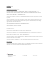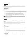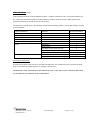
1
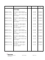
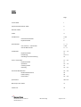
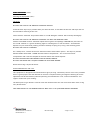
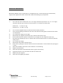
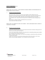
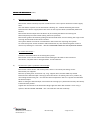
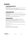
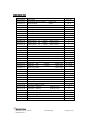
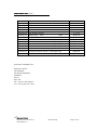
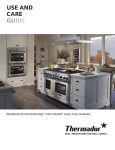
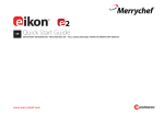
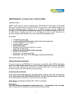
MV 3 SERIES
GENERAL
GENERAL PURPOSE
OPEN TOP RANGES
OWNER’S MANUAL
Country of Destination
GB and IE
Manual Part No: 933928-01
Manual Rev No: 1
MD Gas Range
- Page 1 of 32 –
IMPORTANT CUSTOMER INFORMATION
Please check the gas tap and thermostat will press and release
freely prior to lighting the burner, as this is part of the unit’s
safety mechanism.
It is particularly important to check this following spillage as
solidified fats and carbonised meat juices can impair the
valves correct operation.
IMPORTANT INFORMATION INSTALLATION ENGINEER
Please ensure the customer is made fully aware of how the
gas tap and thermostat operate and the importance of
checking its operation daily.
Manual Part No: 933928-01
Manual Rev No: 1
MD Gas Range
- Page 2 of 32 –
Model No.
Product Description
Rev.
Date
Flexible Hose
Size
Mv2 Gas Ranges
MV3RGP60-OT-NG
600 Open Top 4 Burner Range NG
1
01-02-08
¾” BSP hose
MV3RGP60-OT-NG-C
600 Open Top 4 Burner Range NG With
1
01-02-08
¾” BSP hose
1
01-02-08
¾” BSP hose
Castors
MV3RGP60-OT-NGV
600 Open Top 4 Burner Range NG with
¾” BSP hose
VE Pan Supports
MV3RGP90-OT-NG
900 Open Top 6 Burner Range NG
1
01-02-08
¾” BSP hose
MV3RGP90-OT-NG-C
900 Open Top 6 Burner Range NG With
1
01-02-08
¾” BSP hose
1
01-02-08
¾” BSP hose
Castors
MV3RGP90-OT-NGV
900 Open Top 6 Burner Range NG with
VE Pan Supports
MV3RGP120-OT-NG
1200 Open Top 8 Burner Range NG
1
01-02-08
¾” BSP hose
MV3RGP120-OT-NG-C
1200 Open Top 8 Burner Range NG
1
01-02-08
¾” BSP hose
1
01-02-08
¾” BSP hose
With Castors
MV3RGP120-OT-NGV
1200 Open Top 8 Burner Range NG
with VE Pan Supports
MV3RGP60-OT-LP
600 Open Top 4 Burner Range LP
1
01-02-08
¾” BSP hose
MV3RGP60-OT-LP-C
600 Open Top 4 Burner Range LP With
1
01-02-08
¾” BSP hose
1
01-02-08
¾” BSP hose
Castors
MV3RGP60-OT-LPV
600 Open Top 4 Burner Range LP with
VE Pan Supports
MV3RGP90-OT-LP
900 Open Top 6 Burner Range LP
1
01-02-08
¾” BSP hose
MV3RGP90-OT-LP-C
900 Open Top 6 Burner Range LP With
1
01-02-08
¾” BSP hose
1
01-02-08
¾” BSP hose
Castors
MV3RGP90-OT-LPV
900 Open Top 6Burner Range LP with
VE Pan Supports
MV3RGP120-OT-LP
1200 Open Top 8 Burner Range LP
1
01-02-08
¾” BSP hose
MV3RGP120-OT-LP-C
1200 Open Top 8 Burner Range LP
1
01-02-08
¾” BSP hose
1
01-02-08
¾” BSP hose
With Castors
MV3RGP120-OT-LPV
1200 Open Top 8 Burner Range LP
With VE Pan Supports
Manual Part No: 933928-01
Manual Rev No: 1
MD Gas Range
- Page 3 of 32 –
INDEX
Page
Cover Sheet:
1
Important Information Sheet
2
Revision Sheet:
3
Index:
4
Introduction:
5&6
General Introduction
5
Important Note
6
Specification:
7 – 11
Gas Pressure / Connection
7&8
Overall Dimensions
9 - 11
Installation:
12 – 14
Important Note1
12
Positioning
12 & 13
Checking & Commissioning
14
User’s Instruction:
15 – 22
Important Note
15
Operation
16 - 18
Cooking Guide
19
Cleaning
19 - 22
Service & Maintenance:
23 – 28
Routine Maintenance
23
Fault Finding
24
Instructions
25 - 28
Spare Parts:
29 & 30
Warranty Cover Sheet:
31
Check List:
32
Manual Part No: 933928-01
Manual Rev No: 1
MD Gas Range
- Page 4 of 32 –
INTRODUCTION
This manual contains all the required information to ensure that your new appliance is installed
and serviced correctly as well as providing you with the information necessary to identify and order
spare parts. It also contains comprehensive instructions for the user and for cleaning the appliance.
To maintain peak performance, it is recommended that the appliance be regularly serviced and that
when ordering spare parts, reference is made to the appropriate list quoting the Part Number and
Description contained therein. THE FITTING OF A NON STANDARD PART MAY VOID ANY GUARANTEE.
All work carried out on this appliance during installation or servicing must be performed by a competent
person and the connection of the appliance to the gas supply MUST be carried out by qualified
personnel in accordance, where applicable, with the relevant regulations.
The siting of the appliance and the connection to the gas supply must comply with the latest GAS
SAFETY (INSTALLATION & USE) REGULATIONS 2000: the requirements of the FIRE
PRECAUTIONS ACT 1971; the HEALTH & SAFETY AT WORK, ETC ACT 1974, the BUILDING
STANDARDS (SCOTLAND) CONSOLIDATION REGULATIONS 1971. Detailed recommendations are
contained in British Standards BS5440 Part 1:2000, BS5440: Part 2:2000, BS5588: Part 0:1996, BS5588:
Part 11:1997 & BS6173: 2001.
An easily accessible stopcock must be fitted in the gas supply adjacent to the appliance for use in an
emergency.
The details of the gas supply will be found on the Data Plate, which is located on the rear of the flue
upstand/splashback panel.
Improvements
The policy of Manitowoc Food Service Ltd is such that, each product is subject to continual development
and may, therefore, be subsequently improved. The company reserves the right to alter the design of
any appliance without prior notification and without the responsibility to update any delivered or inservice appliance and furthermore, without incurring the responsibility for altering these instructions. In
such circumstances, it may be found that the appliance detailed herein differs in certain respects from
the one supplied.
IT IS IMPORTANT, THEREFORE, TO QUOTE THE SERIAL No. AND THE APPLIANCE MODEL No.
IN ALL COMMUNICATIONS WITH THE COMPANY.
Manual Part No: 933928-01
Manual Rev No: 1
MD Gas Range
- Page 5 of 32 –
Introduction (cont.)
Important
Before installing any item please refer to the installation instructions.
We recommend that all servicing other than routine cleaning be carried out by our authorised service
agents and will accept no responsibility for work carried out by other persons.
For satisfactory operation, parts of catering equipment become hot. Suitable precautions must be taken
to avoid accidental burns therefore the appliance should be positioned to minimise the possibility of
accidental touching. It is the supervisor’s responsibility to warn users to wear suitable protection and to
follow correct operation and cleaning procedures.
For the details of your nearest Service Agent for all warranty repair work, you should contact:The Service Department,
Ashbourne House
The Guildway
Old Portsmouth Road
Guildford
Surrey
GU3 1LR
Tel: +44 (0) 1483 464902
Fax: +44 (0) 845 301 1461
Spares can be obtained via the Spare Parts Department at the above address.
IT IS IMPORTANT, TO QUOTE THE SERIAL No. AND THE APPLIANCE MODEL No. IN ALL
COMMUNICATIONS WITH THE COMPANY.
Manual Part No: 933928-01
Manual Rev No: 1
MD Gas Range
- Page 6 of 32 –
SPECIFICATION
900 Open Top Range
6 Open Top Burners with Oven
600 Open Top Range
4 Open Top Burners with Oven
1200 Open Top Range
8 Open Top Burners with Two Ovens
Gas Pressure
Supply Pressure
Adjusted Pressure
Natural Gas
20 mbar (
8” wg)
15 mbar ( 6” wg)
Propane Gas
37 mbar (14.8” wg)
37 mbar (14” wg)
Gas Connection
¾” BSP Taper Male (Rp 3/4”)
Heat Input (Nett Values)
INDIVIDUAL BURNERS ONLY
900 Oven
INJECTOR
NATURAL GAS
PROPANE
NG
LP
m³/h
Btu/h
kW
Kg/h
Btu/h
kW
2.44mm
1.32mm
0.775
24,975
7.32
0.448
19,516
5.72
600 Oven
1.99mm
1.18mm
0.519
16,718
4.90
0.365
15,899
4.66
Open Top
2.27mm
1.32mm
0.561
20.472
6.00
0.493
20.472
6.0
900 Open Top Range
4.615
147,807
43.32
3.407
142’348
41.72
600 Open Top Range
3.079
98,606
28.9
2.337
97’787
28.66
1200 Open Top Range
6.414
205,469
60.22
4.757
199’191
58.38
TOTALS
900 Open Top Range low rate
1.82
600 Open Top Range low rate
1.82
1.74
1200 Open Top Range low rate
1.82
1.74
Manual Part No: 933928-01
Manual Rev No: 1
MD Gas Range
- Page 7 of 32 –
1.74
Specification (cont.)
Burner Injectors
900 Oven
900 Oven By-pass
600 Oven
Natural gas
Propane Gas
2.44mm (41M)
1.32mm (55M)
ADJUSTABLE
0.55mm
1.99mm (47M)
1.18mm (56M)
600 Oven By-pass
ADJUSTABLE
0.55mm
Open Top Burner
2.27mm (43M)
1.32mm (55M)
Adjustable
0.60mm
Open Top Burner Low Rate
Oven Dimensions
900 Oven
600 Oven
Oven Cavity - Width
720mm
425mm
Oven Cavity - Depth
608mm
608mm
Oven Cavity - Height
480mm
Nominal Volume
Shelf sizes
Volume of Cooking Space
0.2m3
(7.4
480mm
ft3)
0.123m3 (4.3 ft3)
685mm x 500mm
385mm x 500mm
0.17m3 (5.9 ft3)
0.09mm3 (3.3 ft3)
Weight
900 Open Top Range
135kg
600 Open Top Range
105kg
1200 Open Top Range
190kg
Manual Part No: 933928-01
Manual Rev No: 1
MD Gas Range
- Page 8 of 32 –
Specification (cont.)
600mm Open Top Range
347
710
G
600
710
769
900
150
945
G
Manual Part No: 933928-01
Manual Rev No: 1
MD Gas Range
- Page 9 of 32 –
Specification (cont.)
900mm Open Top Range
347
710
G
900
710
769
900
150
945
G
Manual Part No: 933928-01
Manual Rev No: 1
MD Gas Range
- Page 10 of 32 –
Specification (cont.)
1200mm Open Top Range
856
710
G
1422
710
769
900
150
945
G
Manual Part No: 933928-01
Manual Rev No: 1
MD Gas Range
- Page 11 of 32 –
INSTALLATION
Important
Your attention is drawn to the latest GAS SAFETY (INSTALLATION & USE) REGULATIONS 2000.
This appliance MUST be installed by a competent person in accordance with these and any other relevant
regulations. Users, too, should be aware of the regulations governing the use of gas appliances,
particularly with respect to the need for regular servicing.
Before Installation
Before commencing installation, remove all packaging materials from the appliance. It is suggested that
any protective film adhering to the stainless steel panels should be left on until installation is completed.
BUT THIS MUST BE REMOVED BEFORE COMMISSIONING OR OPERATING THE APPLIANCE.
Check the appliance Data Plate (located on the rear of the flue upstand/splashback panel), to ensure that
the appliance is suitable for the gas supply available.
Ensure that the floor upon which the appliance is to stand is level and capable of adequately supporting
the weight of the appliance. Legs in place of castors are recommended where the floor is found to be
uneven.
THE FLOOR MUST BE FIRE-PROOF. If it is not, or if any adjacent wall or surface is made of a
combustible material, then the installer MUST ensure that the requirements of the LOCAL FIRE
REGULATIONS are observed.
Positioning
Place the appliance in position allowing a minimum gap of 150mm (6”) at the rear and at least 150mm
(6”)* between the sides of the appliance and any adjacent wall. If the appliance is being suited then
please refer to the separate instructions. The minimum distance between the hotplate and any overshelf
or ceiling constructed of a combustible material must be 1525mm (60”).
For Elevated appliances the minimum distance between the top of the unit and any overshelf or ceiling
constructed of a combustible material must be 600mm (24”), or 450mm (17.7”) for non combustible
material.
Adequate ventilation is essential for safe operation of a gas appliance. A supply of fresh air is necessary
for the correct combustion of the gas and there must be a means of exhausting the heat and the
products of combustion from the kitchen. It is recommended that the appliance be sited below a
ventilating hood, one preferably connected to an extractor system incorporating a grease filter.
These appliances are to be installed with sufficient ventilation to prevent the occurrence of unacceptable
concentrations of substances harmful to health in the room in which they are installed
Manual Part No: 933928-01
Manual Rev No: 1
MD Gas Range
- Page 12 of 32 –
Installation (cont.)
Important Note
The appliance MUST NOT be connected DIRECTLY to a flue or ventilating system, although the flue
products of two or more appliances may be directed into a common outlet when building a suite of
appliances (see separate instructions for suiting appliances).
Legs in place of castors are recommended where the floor is found to be uneven, ensure that the
appliance is level in two places - front to rear and side to side. To check the level it is recommended that
a spirit level be placed on a shelf in the open oven - NOT on top of the hotplate! Level can be achieved
by adjusting any or all of the screw in feet in each corner of the base. Turn anti-clockwise to lower and
clockwise to raise the corner.
Gas Connection
Natural Gas: The size of the supply pipe should be no smaller than ½” BSP and an easily accessible
stopcock must be fitted in the gas line adjacent to the appliance. The gas governor provided with the
appliance MUST be fitted in the supply line BETWEEN the stopcock and the appliance.
Although a rigid gas pipe is recommended, armoured flexible pipe of a GAS COUNCIL APPROVED
PATTERN may be used.
NOTE:
NOTE
Due to the pressure loss through the snap connection fitting on flexi hoses you must fit a 1 “
flexible hose to the following models:
models
MV2RGP120
MV2RGP120RGP120-0T0T-NG
Ensure that all the pipes to the appliance are clean and free from swarf etc, BEFORE making the final
connection.
Propane Gas: Follow the same procedure as that for Natural Gas EXCEPT that the Gas Governor MUST
NOT be fitted - the Gas Supply Tank or Cylinders are already fitted with a Gas Regulator.
Leak Test
Clean off any protective film from the stainless steel panels.
AT THIS STAGE, LEAK TEST THE WHOLE SYSTEM. THE GAS SAFETY REGULATIONS require that ALL
connections in the gas supply line between the Gas Meter and the appliance is tested for gas leaks.
THIS MUST BE DONE BEFORE COMMENCING TO COMMISSION THE APPLIANCE.
Manual Part No: 933928-01
Manual Rev No: 1
MD Gas Range
- Page 13 of 32 –
Installation (cont.)
Checking and Commissioning (cont.)
ALTHOUGH EVERY APPLIANCE IS TESTED AND SET BEFORE IT LEAVES THE FACTORY, IT IS
IMPORTANT THAT THE INSTALLER RE-CHECKS CERTAIN FUNCTIONS BEFORE LEAVING THE SITE.
CHECK THE GAS PRESSURE AT THE APPLIANCE THUS: The pressure test point is located on the manifold rail behind the front control panel, which is secured
by screws.
Connect a manometer (U tube) to the test point. For the 600 and 900 ranges light the oven and 3 top
burners. For the 120 Range light both the ovens and 4 top burners. Check that the pressure reading
agrees with that stated on the data Plate.
SHOULD ADJUSTMENT BE NECESSARY, PROCEED AS FOLLOWS: FOR PROPANE GAS, REFER TO SUPPLIER.
On the gas governor:Remove the cap in order to gain access to the pressure adjusting screw.
Turn the pressure adjusting screw clockwise to increase the pressure or anti-clockwise to decrease it.
When the pressure reading is correct, refit the cap to the governor.
Turn the gas supply to the unit OFF at the stopcock and disconnect the manometer (U tube). Ensure that
the pressure test point screw is refitted.
Turn the gas supply to the appliance on at the stopcock and leak test the pressure test point.
Burner Aeration
The aeration of all the burners is fixed and does not need adjusting. . Do not disturb the air combustion
admission or the combustion products evacuation on open top burners.
Manual Part No: 933928-01
Manual Rev No: 1
MD Gas Range
- Page 14 of 32 –
USERS INSTRUCTIONS
Important Note!
The attention of the user is drawn to the requirements of the GAS SAFETY (INSTALLATION & USE)
REGULATIONS 2000. This appliance MUST be used in accordance with those, particularly so in respect
of the need for regular servicing.
The attention of the user is also drawn to the requirement that those parts that have been protected by
the manufacturer or his agent are not to be adjusted by the user.
See also the sections of this manual referring to Cleaning and General Maintenance.
Safety Note:
only
ly be used by qualified personnel.
This appliance is intended for professional use and shall on
Take care when opening the oven door while the cooking chamber is still hot. note other Parts and
surfaces of this appliance also become hot during use. It is the responsibility of the kitchen supervisor to
inform and warn every user and kitchen worker of this and, furthermore, to ensure those users wear and
use protective clothing when operating the appliance.
Should any adjustment or attention be necessary, you are advised to contact your nearest GAS SAFE
Registered Installer/ Service Engineer immediately. The need for regular servicing is detailed in the GAS
SAFETY (INSTALLATION & USE) REGULATIONS 2000.
IF YOU THINK THAT GAS IS ESCAPING, ACT IMMEDIATELY. SHUT OFF THE GAS SUPPLY AT THE
METER OR EMERGENCY CONTROL, CONTACT THE SUPPLIER OF YOUR GAS IMMEDIATELY.
MAKE SURE THAT ALL USERS OF THIS APPLIANCE KNOW WHERE THE GAS SUPPLY STOPCOCK IS
LOCATED FOR THE USE IN AN EMERGENCY.
Improvements
The policy of Manitowoc Food Service Ltd is such that each product is subject to continual improvement.
The company reserves the right to alter the design of any appliance without prior notification and
without the responsibility to update any delivered or in-service appliance and, furthermore, without
incurring the responsibility for altering these instructions. In such circumstances, it may be found that
the appliance detailed herein differs in certain respect from the one supplied.
For further details or enquires please contact:
The Service Department,
Ashbourne House
The Guildway
Old Portsmouth Road
Guildford
Surrey
GU3 1LR
Tel: +44 (0) 1483 464900
Manual Part No: 933928-01
Manual Rev No: 1
MD Gas Range
- Page 15 of 32 –
Users Instructions (cont.)
Pan size
The maximum pan size to be used is 34cm and the minimum pan size to be used is 12cm to ensure
satisfactory combustion and stability
Lighting Instructions:
Open Hotplates
1)
To turn on an individual open top hotplate burner, push in the appropriate gas tap knob and
turn it anti-clockwise to the double flame position, the “Full ON” position. At the same time apply
a lighted taper to light the burner head.
2)
Keep knob depressed for a further 20 seconds until flame is established.
3)
If flame is extinguished on releasing knob, wait 3 minutes then repeat steps 1 & 2.
4)
To turn down or lower the heat, turn the gas tap knob anti-clockwise from the “Full On” position
until the desired flame height is reached. Turned fully anti-clockwise to the single flame
position, is the lowest setting.
Note!
Note When first lighting the appliance or after installation or after an extended shut-down period, it
may be necessary for gas control knob to remain pushed in for some time before burner will light, owing
to the presence of air in gas line.
To Turn Off:
Turn the gas tap knob fully clockwise (beyond the “Full On” position) to the “Off” position●.
Drip Tray:
A drip tray is fitted beneath the burners to catch any spillage. During normal use this drip tray and
handle get hot. Only remove the tray after it has cooled or with suitable gloves.
Oven
Lighting Instructions:
Open the oven doors. The oven burner is visible with the spark electrode and thermocouple secured to
it.
1)
Open the oven door.
2)
Turn the thermostat knob (B) anti-clockwise to the ignition position ✸ and at the same time
press the spark ignition button on the front of the oven base to generate a spark.
Manual Part No: 933928-01
Manual Rev No: 1
MD Gas Range
- Page 16 of 32 –
Users
Users Instructions (cont.)
3)
Keep the thermostat knob depressed for a further 20 seconds until the flame is established.
4)
If the flame is extinguished on releasing knob, wait 3 minutes then repeat steps 2 & 3.
5)
When the flame is established, turn the thermostat knob to the required setting and note the
burner comes ON FULL. Close the oven door securely.
Manual Part No: 933928-01
Manual Rev No: 1
MD Gas Range
- Page 17 of 32 –
Users Instructions (cont.)
Lighting Instructions: (cont.)
When setting the thermostat knob to the required temperature, turn the knob to Mark 9 (maximum)
AND THEN back to the required setting.
Note! When first lighting the appliance or after installation or after an extended shut-down period, it
may be necessary for gas control knob to remain pushed in for some time before burner will light, owing
to the presence of air in gas line.
To Turn Off:
Turn the thermostat knob clockwise to the “OFF” position.
Using the Oven:
There are 6 shelf positions provided so that the two shelves can be put at different heights.
The hottest part of the oven being at the top, and the coolest at the bottom. The oven temperatures in
the following table are those at the centre of the oven.
The temperature guide given below is only intended as a guide to the gas mark settings on the
appliances thermostat knob. It is provided in order to, assist the user to adapt a temperature or a
cooking time given in a recipe. The actual temperature at the centre of the oven has been determined by
the manufacturer and it will not necessarily correspond to the guides given elsewhere. Using this guide
should produce the desired result but it is strongly recommended that the user make note of the best
results for future reference.
Mark
1
2
3
4
5
6
7
8
9
°C
144
158
172
186
200
215
230
245
260
°F
291
316
342
367
392
419
446
473
500
The temperatures will vary from the above figures by as much as 20°C hotter at the top of the oven and
30°C cooler towards the bottom of the oven. But remember these are temperatures in an empty oven.
To cook identical products on two shelves, select two shelf positions with a sufficient gap between them
to allow air movement in the oven. For example, cooking small cakes or pastry use shelf positions 2 & 5,
counting from the top of the oven. Allow the food to cook for just over half the normal time and then
change the position of the shelves.
As an alternative leave the food on the upper shelf until it is cooked, then move the food from the lower
shelf to the upper shelf, or leave on the lower shelf until cooked.
Manual Part No: 933928-01
Manual Rev No: 1
MD Gas Range
- Page 18 of 32 –
Users Instructions (cont.)
Cooking identical foods on three different shelves is seldom satisfactory and is not recommended, but
the “cool zone” at the oven bottom can be sometimes used for slow casseroles, whilst general and
specialised cooking is carried out on the two shelves.
The following cooking chart is for guidance on thermostat settings. Make a note of the settings you find
most acceptable.
Usage and Method
Products
Thermostat Setting
High Temperature Roasting
Meat or Poultry
6 or 7
Low Temperature Roasting
Meat or Poultry
3
High Temperature Baking
Bread or Scones
8
Medium Temperature Baking
Queen Cake sponge
5
Low Temperature Baking
Slab Cake
2
Pastry
Puff Pastry
8
Flaky Pastry
7
Hot Water Pastry (Pork Pies etc)
4
Shortcrust Pastry
6
Plate Tarts
6
Milk Pudding
3
Baked Custard
3
Puddings
Cleaning the Equipment:
It will be found that it takes less time and effort if appliances are cleaned every day, particularly while
they are still warm and before grease or spillage’s are burnt on.
PROPRIETARY OVEN CLEANER MUST BE USED WITH CARE. THEY ARE HIGHLY CORROSIVE AND MAY
CAUSE DAMAGE TO SURFACES AND COMPONENTS.
Manual Part No: 933928-01
Manual Rev No: 1
MD Gas Range
- Page 19 of 32 –
Users Instructions (cont.)
Cleaning the Equipment (cont.)
Open Top Hotplates
Wipe the open top pan support grids clean of grease and spillage’s regularly - even during cooking
sessions - a crust of burned on carbon, coating the pan supports is unsightly, is a health hazard and will
impair cooking efficiency.
Daily: Soak the pan support grids in a mild solution of grease dissolving agent or detergent - DO NOT
USE A CAUSTIC CLEANING AGENT - and wash. Accumulated deposits may be removed by soaking and
then carefully scraping or a fine cleaning paste could be tried.
SOME PAN SUPPORT GRIDS ARE VITREOUS ENAMELLED - DO NOT USE CAUSTIC CLEANERS AT ALL.
WIPE OVER WITH A LIGHT COATING OF COOKING OIL AFTER CLEANING AND DRYING.
The burner caps and burner rings may be removed from the open hotplate burners for cleaning. Soak
and wash in a mild detergent solution, rinse and dry thoroughly before replacing. DO NOT allow water
or cleaning agents to enter the burner venturi.
DO NOT use caustic cleaners on burner parts. DO NOT scrape or poke the burner port ring, soak and
then carefully BRUSH clean any stubborn accumulations of dirt.
REPLACE THE BURNER COMPONENTS CAREFULLY IN THEIR CORRECT POSITIONS.
Brush or scrape all accumulated rubbish from the burner tube covers into the hotplate drip tray. Wipe
down with a grease absorbing material.
Remove the full width drip shield by removing the pan supports and burner caps/rings first. The drip
shield can cleaned by washing with a mild detergent solution, rinse and dry before replacing. This is one
of those jobs which MUST be carried out on a daily basis and IMMEDIATELY following a spillage.
The Oven
The oven shelves and the oven shelf supports can be removed for cleaning. Withdraw the shelves in the
normal way, rub them free of grease using an absorbent paper pad and wash in a hot detergent solution.
Rinse and dry before replacing.
The shelf supports are removed by lifting them free from their locating brackets and withdrawing them
from the oven interior. They, too, can be washed in a hot detergent solution and rinsed and dried before
replacing.
Clean the oven interior and the oven door-lining daily using a hot mild detergent solution. This is
especially necessary if a spillage has occurred, meat has been roasted or fruit pies baked. Rinse with
clean water. Stubborn accumulations can be gently scraped off after soaking.
Manual Part No: 933928-01
Manual Rev No: 1
MD Gas Range
- Page 20 of 32 –
Users Instructions (cont.)
Cleaning the Equipment (cont.)
The Oven
DO NOT USE CAUSTIC OR ABRASIVE CLEANING AGENTS.
Leave the oven drip tray in position while you clean the oven, it will collect all the bits and drips and can
be removed for cleaning at the sink.
Clean stainless steel with soap and hot water or a mild detergent solution. Rinse and dry thoroughly.
DO NOT USE CAUSTIC OR ABRASIVE CLEANERS. DO NOT USE ABRASIVE PADS.
Vitreous enamelled surfaces should be wiped clean of grease and Spillage’s BEFORE they are burnt on.
Use a mild solution or a grease dissolving agent or a detergent as a soak and wash. Accumulated
deposits may be removed by soaking and then carefully scraping or by using a fine cleaning paste.
DO NOT USE CAUSTIC CLEANERS.
On a weekly basis, remove all the oven furniture and the oven bottom panels - the drip tray and the
bottom baffles when fitted. CLEAN OUT the bottom compartment - this is the oven burner
compartment and it must be emptied of all loose debris and carbon deposits.
DO NOT DISTURB THE OVEN BURNER OR ELECTRODE/SENSOR.
DO NOT USE WATER OR A LIQUID CLEANER ON THE OVEN BURNER.
Brush clean using a dry bristle brush.
General Maintenance and Care.
This equipment is designed and manufactured to give you long, satisfactory service at low cost, provided
that it is given proper care and attention at all times. Frequent cleaning and regular checking of correct
adjustment will be rewarded by reduced operating and maintenance costs, minimum downtime, and
regular results from your cooking.
The flame ports of gas burners must be clean and unobstructed. The user must brush them clean, using
a dry bristle brush.
THE UNBLOCKING OF GAS BURNER PORTS IS BEST LEFT TO A QUALIFIED SERVICE ENGINEER
Manual Part No: 933928-01
Manual Rev No: 1
MD Gas Range
- Page 21 of 32 –
Users Instructions (cont.)
General Maintenance and Care (cont.)
All gas taps and gas controls must operate smoothly and freely without sticking or jerking. A QUALIFIED
SERVICE ENGINEER MUST carry out re-lubrication if required.
WE RECOMMEND THAT ALL EQUIPMENT IS SERVICED AT LEAST ONCE A YEAR, BUT MAY BE AS
FREQUENT AS 6 MONTHS OR LESS IN HEAVY USE ENVIROMENTS OR IF THE GAS TAPS/THERMOSTAT
AND GAS CONTROLS DO NOT OPERATE FREELY. ALL WORK MUST BE CARRIED OUT BY A QUALIFIED
SERVICE ENGINEER.
SERVICE INTERVALS CAN BE AFFECTED BY SPILLAGE AND SHOULD BE ASSESSED EACH TIME THE
EQUIPMENT HAS BEEN USED.
Manual Part No: 933928-01
Manual Rev No: 1
MD Gas Range
- Page 22 of 32 –
SERVICE AND MAINTENANCE
Maintenance MUST only be carried out by a competent person. Ensure that the gas and electricity
supply to the appliance has been turned “OFF” before dismantling any components.
Routine Maintenance Procedure:
1)
Turn “ON” the oven or both ovens on a 120 range (and three top burners or 4 on a 120 range)
and Check that the gas pressure at the test point is as stated on the data plate.
Natural Gas – 15 mbar (6” wg)
Propane Gas – 37 mbar (14” wg)
2)
Turn on each hotplate burner in both full and turn-down positions.
3)
Carry out the lighting procedure for the oven and check that the ignition and the burner flames
4)
Turn off the gas supply to the range.
5)
Remove the pan supports and burner caps. Clean out the burner Caps.
6)
Ensure that the burner injectors and burner air passages are clear. Replace burner caps.
7)
Re-grease the hotplate gas taps as required and ensure that the barrels are secured by the two
8)
Turn on the gas supply.
are satisfactory.
niting screws.
9)
Remove the oven shelves and drip trays.
10)
Brush off any spillage on the oven burner. Ensure the electrode is clean and that the spark gap is
11)
Check the condition of the door seals and doors are not leaking.
12)
Replace oven furniture.
13)
Check the operation of the thermostat and re-grease if necessary.
14)
Light each burner in turn and check full and turn-down rate.
15)
Replace the pan supports.
16)
Check the oven lighting procedure.
3-4mm.
Manual Part No: 933928-01
Manual Rev No: 1
MD Gas Range
- Page 23 of 32 –
Service and Maintenance (cont.)
Fault
OPEN TOP BURNER
Burners will not stay
alight.
Possible Cause
Faulty connection at
thermocouple valve.
Thermocouple incorrectly
located.
Burner goes out when
turned too “low”.
Irregular flame.
OVEN
Failure to ignite
Make re-connection
Re-position thermocouple
Blockage in tap.
Clean and re-grease.
By-pass too low
Adjust by-pass screw.
Burner ring, cap not located.
Re-locate
Low pressure.
Check pressure at Test Point.
Accumulation of dirt or grease
around burner ports
Connection broken or
disconnected
Burner fails to establish
Remedy
Clean
Replace Lead/reconnect
Loose thermocouple
Tighten thermocouple
Electro-magnetic unit failure
Replace gas taps.
By-pass too low
Adjust by-pass screw.
Oven too hot or cold
Thermostat calibration out
Re-calibrate or replace
Main burner will not stay
Loose thermocouple or
alight
Thermocouple incorrectly
on minimum rate.
located.
Main burner goes
By Pass flame set too low
Tighten, Reposition
thermocouple
Increase bypass rate
out whilst in use
Manual Part No: 933928-01
Manual Rev No: 1
MD Gas Range
- Page 24 of 32 –
Service and Maintenance (cont.)
ENSURE THAT THE GAS SUPPLY TO THE APPLIANCE HAS BEEN TURNED OFF BEFORE REMOVING OR
DISMANTLING ANY GAS CONTROLS.
1)
Removal of Oven Thermostat/FFD.
Remove the shelves and drip tray from the oven together with the hotplate drip tray(s).
Pull off all the control knobs from the horizontal control panel, and remove by unscrewing the
two fixing screws. Remove rubber thermostat shroud by pulling off thermostat spindle.
From inside the oven, unclip the thermostat phial from its holder and ease it through the top
panel.
Remove the pan supports together with the burner caps and skirts.
Also lift off the full width drip shield.
ENSURE THAT THE THERMOSTAT PHIAL IS NOT KINKED – HAS NO SHARP BENDS AND IS CORRECTLY
LOCATED IN ITS HOLDER.
2)
Removal of Oven Thermocouple.
Disconnect the thermocouple-sensing tip from the RH side of the oven burner (taking note of its
position) by unscrewing the M8 fixing nut.
Access to the thermocouple connection on the thermostat is obtained by following the procedure
for removing the Oven Thermostat (Section 1).
When re-fitting the thermocouple, ensure that the sensing tip is positioned correctly with the tip
inside the flame pattern.
Tighten the connection to the thermostat finger tight and then add a further ¼ turn using a
spanner, DO NOT OVER-TIGHTEN - this can break the seal and continuity.
Manual Part No: 933928-01
Manual Rev No: 1
MD Gas Range
- Page 25 of 32 –
Service and Maintenance (cont.)
3)
Removal of Oven Burner or Burner Injector.
Remove the shelves and drip tray from inside the oven. This exposes the burner and its supply
tube.
The oven burner injector can be removed for cleaning, etc., without disturbing the burner.
Disconnect the burner supply tube at the union on the injector elbow (immediately before the
burner).
Remove the thermocouple from the burner by unscrewing the M8 nut and easing the
thermocouple tip from the basket (taking note of its position).
Remove the ignition electrode by pulling off the electrode lead, and unscrewing the single screw
securing the electrode to the burner bracket.
The injector elbow can now be unscrewed from the burner thus exposing the injector.
To clean the injector, brush off with a stiff bristle brush any dirt, blow through the orifice to
remove any blockage or restriction - DO NOT POKE WIRE THROUGH THE INJECTOR ORIFICE.
To remove the burner: Proceed as described above for removing the injector.
Remove the screws at each side of the burner holding the brackets to the oven base.
The burner, complete with its fixing brackets, can be lifted out.
4)
To Remove a Open Top Burner Thermocouple.
Remove the control knobs and control panel, which is secured by two fixing screws.
Remove the pan supports.
Remove, by lifting clear, the burner cap, ring, support (skirt) and full width drip shield.
Disconnect the thermocouple-sensing tip from the burner rail (taking note of its position) by
unscrewing the M8 fixing nut. Unscrew the thermocouple from the Gas Tap/FFD and withdraw
the thermocouple.
When re-fitting the thermocouple, ensure that the sensing tip is positioned correctly with the tip
inside the flame pattern.
Tighten the connection to the thermostat finger tight and then add a further ¼ turn using a
spanner, DO NOT OVER-TIGHTEN - this can break the seal and continuity.
Manual Part No: 933928-01
Manual Rev No: 1
MD Gas Range
- Page 26 of 32 –
Service and Maintenance (cont.)
5)
To Remove or clean a Open Top Burner Injector.
Remove the pan supports.
Remove, by lifting clear, the burner cap, Brass ring, Burner ring (skirt) and full width drip shield.
The injector can be unscrewed using a suitable socket spanner.
To clean the injector, brush off with a stiff bristle brush any dirt, blow through the orifice to
remove any blockage or restriction - DO NOT POKE WIRE THROUGH THE INJECTOR ORIFICE.
6)
Servicing and removing a Gas Tap/FFD.
Remove the control knobs and control panel, which is secured by two fixing screws.
Remove the pan supports.
Remove by lifting clear, the burner cap, Brass ring, Burner ring (skirt) and full width drip shield.
The front of the gas tap is now exposed and the procedure for cleaning and re-greasing the tap
can be carried out.
Remove the gas tap from the gas rail by unscrewing the supply tube union connection and
unscrew the single screw in the clamping bracket below the gas tap.
To clean and re-grease a gas tap: Remove the front cover from the gas tap by unscrewing the two Pozi head screws.
Carefully withdraw the cover taking care not to lose the small spring from inside the tap.
Carefully pull the taper plug from the body of the gas tap.
Clean the plug and the inside of the body using a lint-free cloth and a suitable solvent.
Wipe both parts clean and dry. Ensure that all the holes are clean and free from obstruction.
Lightly re-grease the plug using suitable high temperature grease, such as Rocol, and replace
the plug in the gas tap body.
Lightly grease the inside of the gas tap front cover, position the spring and re-assemble the
front cover to the body.
DO NOT WORK ON MORE THAN ONE TAP AT A TIME.
ENSURE THAT THE PLUG IS PLACED IN THE CORRECT BODY.
Manual Part No: 933928-01
Manual Rev No: 1
MD Gas Range
- Page 27 of 32 –
Service and Maintenance (cont.)
10)
To Convert NG Appliances to LP Gas. (Open Top)
Remove the control knobs and control panel, which is secured by two fixing screws.
Remove the pan supports.
Remove the hotplate burner injectors as described in Section 5 and fit replacement 1.32mm LP
injectors (933915-01) and re-fit burner caps etc.
Working from the front of the appliance screw in fully both the thermostat and Gas Tap/FFD bypass screws.
From inside the oven remove the oven injector as described in Section 3 and fit replacement LP
injector.
900 Range – 1.32mm (924024-09)
600 Range – 1.18mm (924024-06)
Remove the gas governor from the inlet supply pipe.
Finally fit replacement Data Plate and re-test the appliance.
11)
To Convert LP Appliances to NG Gas. (Open Top)
Proceed as described in Section 10, but substituting NG replacement parts.
Hotplate Injector
2.27mm (933916-01)
Oven Injector 900
2.44mm (924024-08)
Oven injector 600
1.99mm (924024-10)
Governor
(931779-01) 3/4 Governor
Fit replacement gas governor to the inlet supply pipe.
Turn the thermostat by-pass screw anti-clockwise and light the oven burner. Ensure that when
the burner cuts-down to by-pass rate the flame envelops the thermocouple tip sufficiently to
keep the magnet valve open.
If the flame extinguishes turn the by-pass screw anti-clockwise until the flame is established.
Repeat the above procedure for the hotplate by-pass rates.
Finally fit replacement Data Plate and re-test the appliance.
Manual Part No: 933928-01
Manual Rev No: 1
MD Gas Range
- Page 28 of 32 –
SPARE PARTS LIST
Part Number
Description
Quantity
927123-S1
Thermostat/FFD (0.55mm)
(Open Top)
1
932329-01
Thermocouple
(Oven)
930875-02
Thermostat Knob
1
929344-02
Piezo Ignition Unit
1 or 2
930389-01
Oven Ignition Lead
1 or 2
930734-01
Oven Ignition Electrode
930733-01
Oven Burner
(900) & (120)
1
930733-02
Oven Burner
(600) & (120)
1
924024-08
Oven Injector
NG 2.44mm
(900) & (120)
1
924024-09
Oven Injector
LP
1.32mm
(900) & (120)
1
924024-10
Oven Injector
NG 1.99mm
(600) & (120)
1
924024-06
Oven Injector
LP
(600) & (120)
1
1or 2
1 or 2
1.18mm
931457-S2
Gas Tap/FFD (0.6mm)
933911-01
Thermocouple
(Open Top)
8, 6 or 4
930875-01
Control Knob
(Open Top)
8,6 or 4
933907-01
Burner Body c/w NG Injector
(Open Top)
8, 6 or 4
933914-01
Burner Body c/w LP Injector
(Open Top)
8, 6 or 4
927123-07
Olive 10mm Dia
(Open Top)
8,6 or 4
932869-06
Nut 10mm Dia
(Open Top)
8,6 or 4
933908-01
Brass Burner Ring
(Open Top)
8, 6 or 4
933916-01
Burner Inj.
NG
2.27mm
(Open Top)
8, 6 or 4
933915-01
Burner Inj.
LP
1.32mm
(Open Top)
8, 6 or 4
933909-01
Burner Cap Black
(Open Top)
933912-01
8mm Dia burner nut (m13x1)
(Open Top)
933913-01
8mm Dia burner Olive
(Open Top)
933918-01
Burner ring (Aluminum skirt)
924402-06
Hinge Pin (Adjustable)
932308-01
Arch Handle
1 Per Door
932659-01
Door Magnet
1 Per Door
932574-01
LH Top RH Bottom Hinge
932574-02
RH Top LH Bottom Hinge
921913-09
Door Seal – 362mm
(900) & (120)
2
921913-08
Door Seal – 445mm
(900) & (120)
2
921913-08
Door Seal – 445mm
(600)
930829-01
Oven Shelf Support RH
1or 2
930829-02
Oven Shelf Support LH
1 or 2
924435-01
Oven Shelf.(900) & (120)
2
924435-02
Oven Shelf.(600) & (120)
2
Manual Part No: 933928-01
Manual Rev No: 1
8, 6 or 4
4
1,2 or 3
1,2 or 3
MD Gas Range
3
- Page 29 of 32 –
SPARE PARTS
PARTS LIST (Cont.)
Part Number
Description
Quantity
932853-01
Leg 65mm Dia
4
932811-01
Castor swivel braked
2
932811-02
Castor swivel Un-braked
2
931779-01
Gas Governor 3/4 Inch (NG only) (600),(900)&(120)
1
932599-02
Pan Support Enamel
2, 3 or 4
930735-S1
Burner Assy
Oven
(900)
Spares Kit
930735-S2
Burner Assy
Oven
(600)
Spares Kit
933930-S1
Conversion Kit NG to LPG
90R (Open Top)
Spares Kit
933930-S2
Conversion Kit LPG to NG
90R (Open Top)
Spares Kit
933930-S3
Conversion Kit NG to LPG
60R (Open Top)
Spares Kit
933930-S4
Conversion Kit LPG to NG
60R (Open Top)
Spares Kit
933930-S5
Conversion Kit NG to LPG 120R (Open Top)
Spares Kit
933930-S6
Conversion Kit LPG to NG 120R (Open Top)
Spares Kit
Spare Parts available from:
Ashbourne House
The Guildway
Old Portsmouth Road
Guildford
Surrey
GU3 1LR
Tel: +44 (0) 1483 464903
Fax: +44 (0) 845 301 1463
Manual Part No: 933928-01
Manual Rev No: 1
MD Gas Range
- Page 30 of 32 –
WARRANTY COVER
The Company offer twelve months warranty with each new piece of equipment subject
to our normal conditions of sale and will undertake responsibility for warranty subject to
the additional following conditions.
Notice of the defect/damage is given within 48 hours of breakdown or in the case of
damage four days from the date of despatch and the manufacturer given adequate
opportunity to examine the goods in order that appropriate action can be taken.
The Company will not be obliged to repair or replace any goods if after examination the
defect/damage is found to be through accident, misuse, neglect, incorrect installation or
maintenance by other than approved engineers, or any other cause beyond the reasonable
control of the manufacturer.
EXCLUSIONS TO WARRANTY
Normal routine maintenance is not covered and the warranty specifically excludes any
problems, which are related to scale caused by hard water and the cleaning of pilot jets.
Also excluded from the warranty are the following consumable items.
Tap washers and springs, gaskets, oven lamps and indicating lights, door seals and any
other perishable parts.
This warranty in no way prejudices your rights under common law and is offered as an
addition to your statutory rights.
Manual Part No: 933928-01
Manual Rev No: 1
MD Gas Range
- Page 31 of 32 –
CHECK LIST FOR 600/900 MEDIUM DUTY RANGES
RANGES
Description
Part Number
Checked by
DATA PLATE
*
*
CONTROL KNOBS
SHELVES
PAN SUPPORTS
LIGHTING INSTRUCTIONS
Top Burners 930875-01
*
Thermostat 930875-02
*
600 Ranges 924435-02 x 2
*
900 Ranges 924435-01 x 2
*
Matt 932599-02
*
927144-01
*
*
GAS GOVERNOR ¾”
EARTH BONDING KIT
MANUAL
931779-01
Nat Gas Only
*
Earth Bonding Tab 923206-01
*
Earth Bonding Label 923153
*
932871-01
*
This unit was packed with pride by -----------------------------
Manual Part No: 933928-01
Manual Rev No: 1
MD Gas Range
- Page 32 of 32 –