1
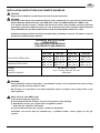
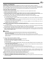
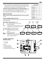
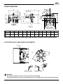
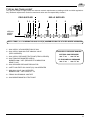
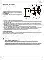
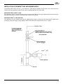
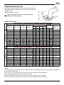
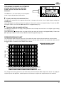
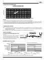
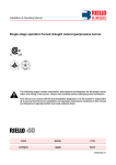
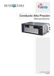
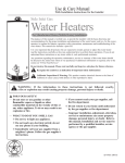
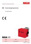
Installation & Operating Manual
Two stage operation forced draught natural gas/propane burner
The following pages contain information, descriptions and diagrams for the proper installation and wiring of the burner. Please read carefully before attempting final installation.
This manual is to remain with the final installation designation. It is the installer’s responsibility to ensure that the burner installation and operation instructions mentioned in this manual
are followed and operated within local code authority limits.
CODE
MODEL
TYPE
3757313
G900
573T
2903245 (0)
GB
TABLE OF CONTENTS
Installation instructions and owner's handbook . . . . . . . . . . . . . . . . . . . . . . . . . . . . . . . . . . . . . . . . . . . . . . . . . . . 2
General information . . . . . . . . . . . . . . . . . . . . . . . . . . . . . . . . . . . . . . . . . . . . . . . . . . . . . . . . . . . . . . . . . . . . . . . 3
Step by step procedure. . . . . . . . . . . . . . . . . . . . . . . . . . . . . . . . . . . . . . . . . . . . . . . . . . . . . . . . . . . . . . . . . . . . . 3
Installation data . . . . . . . . . . . . . . . . . . . . . . . . . . . . . . . . . . . . . . . . . . . . . . . . . . . . . . . . . . . . . . . . . . . . . . . . . . 4
Serial number identification . . . . . . . . . . . . . . . . . . . . . . . . . . . . . . . . . . . . . . . . . . . . . . . . . . . . . . . . . . . . . . . . . 4
Burner components identification . . . . . . . . . . . . . . . . . . . . . . . . . . . . . . . . . . . . . . . . . . . . . . . . . . . . . . . . . . . . . 4
Burner dimensions . . . . . . . . . . . . . . . . . . . . . . . . . . . . . . . . . . . . . . . . . . . . . . . . . . . . . . . . . . . . . . . . . . . . . . . . 5
Electrode & flame probe adjustments. . . . . . . . . . . . . . . . . . . . . . . . . . . . . . . . . . . . . . . . . . . . . . . . . . . . . . . . . . 5
Typical gas train layout. . . . . . . . . . . . . . . . . . . . . . . . . . . . . . . . . . . . . . . . . . . . . . . . . . . . . . . . . . . . . . . . . . . . . 6
Installing the burner . . . . . . . . . . . . . . . . . . . . . . . . . . . . . . . . . . . . . . . . . . . . . . . . . . . . . . . . . . . . . . . . . . . . . . . 7
Installation of sediment trap & burner supply . . . . . . . . . . . . . . . . . . . . . . . . . . . . . . . . . . . . . . . . . . . . . . . . . . . . 8
Wiring diagram . . . . . . . . . . . . . . . . . . . . . . . . . . . . . . . . . . . . . . . . . . . . . . . . . . . . . . . . . . . . . . . . . . . . . . . . . . . 9
Burner head setting . . . . . . . . . . . . . . . . . . . . . . . . . . . . . . . . . . . . . . . . . . . . . . . . . . . . . . . . . . . . . . . . . . . . . . 10
Preliminary burner adjustment . . . . . . . . . . . . . . . . . . . . . . . . . . . . . . . . . . . . . . . . . . . . . . . . . . . . . . . . . . . . . . 11
Pressure working chart . . . . . . . . . . . . . . . . . . . . . . . . . . . . . . . . . . . . . . . . . . . . . . . . . . . . . . . . . . . . . . . . . . . . 11
Combustion chamber size . . . . . . . . . . . . . . . . . . . . . . . . . . . . . . . . . . . . . . . . . . . . . . . . . . . . . . . . . . . . . . . . . 12
Combustion checks . . . . . . . . . . . . . . . . . . . . . . . . . . . . . . . . . . . . . . . . . . . . . . . . . . . . . . . . . . . . . . . . . . . . . . 12
Burner start-up cycle . . . . . . . . . . . . . . . . . . . . . . . . . . . . . . . . . . . . . . . . . . . . . . . . . . . . . . . . . . . . . . . . . . . . . 12
Start-up cycle diagnostics . . . . . . . . . . . . . . . . . . . . . . . . . . . . . . . . . . . . . . . . . . . . . . . . . . . . . . . . . . . . . . . . . . 13
Resetting the control box and using diagnostics . . . . . . . . . . . . . . . . . . . . . . . . . . . . . . . . . . . . . . . . . . . . . . . . . 13
Problem solving guide . . . . . . . . . . . . . . . . . . . . . . . . . . . . . . . . . . . . . . . . . . . . . . . . . . . . . . . . . . . . . . . . . . . . 15
Owner information & routine maintenance . . . . . . . . . . . . . . . . . . . . . . . . . . . . . . . . . . . . . . . . . . . . . . . . . . . . . 15
Spare parts . . . . . . . . . . . . . . . . . . . . . . . . . . . . . . . . . . . . . . . . . . . . . . . . . . . . . . . . . . . . . . . . . . . . . . . . . . . . 16
Spare parts list . . . . . . . . . . . . . . . . . . . . . . . . . . . . . . . . . . . . . . . . . . . . . . . . . . . . . . . . . . . . . . . . . . . . . . . . . . 17
Burner start-up form . . . . . . . . . . . . . . . . . . . . . . . . . . . . . . . . . . . . . . . . . . . . . . . . . . . . . . . . . . . . . . . . . . . . . . 18
3245
1
GB
INSTALLATION INSTRUCTIONS AND OWNER'S HANDBOOK
CAUTION:
All gas burners MUST be installed by trained and licensed technicians.
WARNING:
Installation of this burner must conform with local codes requirements or, in the absence of local codes,
with the Standard: National Fuel Gas code ANSI Z223.1-1984, and CAN/CGA B149.1 & 2 AND UL 795.
If an external electrical source is utilized, the conversion burner, when installed, must be electrically
grounded in accordance with local codes or, in the absence of local codes, with the national Electrical
Code, ANSI/NFPA No. 70-1990 and CSA Electrical Code C22.2 No.0 M1982 & C22.2 No 3. 1988.
Authorities having jurisdiction should be consulted before installations are made. The owner is required
to retain this manual for future reference.
TECHNICAL SPECIFICATIONS
FIRING RATES:
HIGH 360,000 TO 900,000 Btu/hr
LOW 250,000 TO 490,000 Btu/hr
NATURAL GAS
PROPANE
HIGH FIRE
LOW FIRE
HIGH FIRE
LOW FIRE
GAS SUPPLY PRESSURES
MIN. 7" wc
MAX. 14" wc
MIN. 7" wc
MAX. 14" wc
MIN. 8" wc
MAX. 13" wc
MIN. 8" wc
MAX. 13" wc
MANIFOLD PRESSURES
MIN. 2.3" wc
MAX. 3.3" wc
MIN. 0.55" wc
MAX. 1.1" wc
MIN. 2.6" wc
MAX. 6.0" wc
MIN. 1.7" wc
MAX. 3.4" wc
POWER
MOTOR
CONTROL MODULE
120 Volts 60 Hz 1 phase
233T 4.3 Amps 3250 rpm 325 rad/s.
RMG 88.62
WARNING:
If the information in these instructions is not followed exactly, a fire or explosion may result causing
property damage, personal injury or death.
Do not store or use gasoline or any other flammable vapours or liquid in the vicinity of this or any
other appliance.
WHAT TO DO IF YOU SMELL GAS:
1) Do not try to light any appliance.
2) Do not touch electrical switches; do not use any phone in your building.
3) Immediately call your gas supplier from a neighbour's phone.
Follow the gas supplier's instructions.
4) If you cannot reach your gas supplier, call the fire department.
Installation and service must be performed by a qualified installer, service agency or the gas
supplier.
3245
2
GB
GENERAL INFORMATION
Your Riello gas burner comes to you completely assembled and factory wired, ready for installation.
Models equipped with the short combustion head have a fixed flange, which bolts directly to the front of the appliance. When equipped with the long combustion head, the burner comes with a universal flange, which when bolted to the appliance, allows the burner to be adjusted for exact positioning in the combustion zone.
STEP-BY-STEP PROCEDURE
1) Remove the burner from the carton, taking care not to lose any of the supplied accessories.
Check for signs of physical damage.
2) Bolt the combustion head and burner to the appliance. Be sure to install the supplied mounting gasket.
Ensure that the burner is level (we suggest using a spirit level) and that the combustion head is centred in the
appliance port. Refer to page 7 for positioning of combustion head relative to the chamber.
3) Check that all gas train connections are tight and make your connections to the incoming gas supply.
a) A sediment trap must be provided.
b) If not already installed, a manual shutoff valve must be supplied. This valve must be upstream of the burner
gas train supply connection.
c) A 1/8" NPT plugged tapping must be installed immediately upstream of the burner gas train supply connection and must be accessible for a test gauge.
d) If required by local codes, provide gas vent lines at the gas regulators and valve (Riello gas trains are
equipped with vent limiting orifices).
e) Perform required gas pressure test on incoming gas supply lines.
NOTE: Details of sediment trap, manual gas valve and test point can be found in installation of sediment trap and burner supply section.
4) Remove the red protective cover by removing the three screws. Make your adjustment of stop gate, (refer to firing
rate specifications and settings charts for details). Replace and secure the air cover plate.
5) Electrical hookup: 120Volt 60 Hz incoming power lines should be connected to Terminals 1 and 2 on burner terminal
block. A manual disconnect switch must be installed in the incoming power lines. Incoming power lines must be rigid
conduit or flexible approved cable.
CAUTION:
The hot wire must be connected to the black lead of the relay: neutral to the white lead.
Do not reverse the polarity.
The burner will not operate with the Phase/Neutral reversed, and the control box may be damaged.
Proper earth ground should be connected to the terminal block mounting plate which should be a solid green wire
to Earth Ground.
6) Start and check the burner functions as follows:
a) Make a final check on both the gas and electrical connections.
b) Check that all adjustments have been completed.
c) Loosen the screw in the manifold gas test point and install a manometer.
d) Switch on power.
e) Set the thermostat at its highest setting and press the burner reset button. Allow the burner to run through a complete cycle to check control functions.
f) Turn on the manual gas valve and reset the safety. At this stage, the burner will open the air shutter and once it
is open, the burner will prepurge for aprox. 25 seconds.
Allow about 66 seconds for the control module to check all the operating circuits.
It may be necessary to repeat the starting cycle several times to free the gas train of entrapped air. If the burner goes to
lockout, reset the safety button.
7) With the burner running and flame established, check the manifold gas pressure. Adjust manifold pressure to the
correct value for the selected firing rate specified in the FIRING RATE SPECIFICATIONS AND SETTINGS chart.
After completing the setting, remove the manometer and tighten the screws.
NOTE: Do not assume the burner is operating at optimum performance.
8) Make your final combustion efficiency test and fine tune the fan air damper as necessary.
Replace the red protective cover and secure with three screws.
9) If the burner is installed on a central warm air furnace, affix the supplied warning labels to the furnace fan cover door
(inside and outside).
3245
3
GB
10) Always do a final set up by checking the gas flow rate by clocking the meter.
Do a complete combustion check with proper test equipment to obtain the
best and safe CO² , O², and CO results. This test must be done by a qualified technician. The maximum CO² level for Natural Gas is 10%.
The maximum CO² level for Propane Gas is 12%. The recommended flue gas
temperature is from 350 degrees Fahrenheit to 550 degrees Fahrenheit.
Fill out the installation data on the label described below and explain the
burner’s essential functions (starting and stopping) to the owner.
Do not forget to give the dealer or service company’s name and address.
INSTALLATION DATA
Note: This label is supplied in the package with the burner and should be
filled out and affixed to the appliance when the conversion burner is
installed.
SERIAL NUMBER IDENTIFICATION
Your Riello burner may have been manufactured in more than one location and therefore there are two possible serial
number identification.
The Riello 9 character serial number, example,
06 01 12345, is identified as follows:
06
= Last two digits of the year of manufacture;
01
= Week of manufacture;
12345 = Increment of 1 for each burner produced – specific
to product code – reset to zero each January 1st.
The Riello 15 character serial number, example,
06 A 8511111 00025, is identified as follows:
06
= Last two digits of the year of manufacture;
A
= BI-week of manufacture;
8511111 = Burner product code;
00025 = Increment of 1 for each burner produced – specific to product code –
reset to zero each January 1st.
BURNER COMPONENTS
IDENTIFICATION
1
2
2
4
5
6
7
Air damper
Servomotor
Motor
Air pressure switch
Wiring terminal block
Control box RMG 88.62
Reset button with lock-out lamp
(06)
Year of
manufacture
(06)
Year of
manufacture
(A)
(01)
(12345)
BI-week of
manufacture
(8511111)
BI-week of
manufacture
Increment
(00025)
BI-week of
manufacture
Increment
7
1
6
2
5
D7338
4
3
3245
4
GB
BURNER DIMENSIONS
B
G
G1
7 7/8” - 200 mm
4 31/32”
128 mm
J
I
E
A
H
L
°
60 45°
30°
F
D7334
D
6 17/32”-166 mm
8 1/4” - 210 mm
C
Model 900
A
B
C
D
inches
47
25
41
19
mm
11
/64 13
298
/32 2
350
/64
67
1
/64
33
9 1/4” - 235 mm
E
3
/4
19
15
D7351
F
G
G1
H
I
J
L
23
23
5
59
63
1
47
/64 4
389
/32
120
10 /8
270
4
/64
125
5
/64
152
9 /16
230
3
/64
95
NOTE: Actual available insertion length must be measured from tip of end cone to face of mounting gasket.
ELECTRODE AND FLAME PROBE ADJUSTMENTS
1 /16 "
9
"
6°
/
9 16
1
3.7
19
/16
"
=
D7339
2.0
=
2÷
Propane orifice
3
Propane adapter
WARNING:
Do not turn the ignition electrode. Leave it as shown in the drawing.
If the ignition electrode is put near the ionization probe, the amplifier of the control box may be damaged.
3245
5
GB
TYPICAL GAS TRAIN LAYOUT
This gas train scope of supply meets the minimum controls requirements according to CGA and AGA regulations.
Any additional requirements needed to meet local codes are the responsibility of others.
FIELD SUPPLIED
1
SEE GAS
SUPPLY
RANGE
2 3
4
RIELLO SUPPLIED
5
6
7
8
9
Ø
NOTE: ITEMS 5, 6 & 7 COMBINATION GAS VALVE(S) ASSEMBLIES MAY BE UTILIZED WHERE APPROVED
1 - GAS SUPPLY & FLOW DIRECTION OF GAS
2 - GAS SUPPLY MAIN SHUTOFF MANUAL VALVE
(FIELD SUPPLIED)
3 - GAS SUPPLY PRESSURE TEST POINT (FIELD SUPPLIED)
4 - GAS TRAIN PIPE DIAMETER SIZE(S):
BURNER G900 1” NPT (REDUCED AT COMBUSTION
HEAD TO 3/4”)
GAS SUPPLY PRESSURE RANGES:
NATURAL GAS PRESSURE:
min. 7” wc - max. 14” wc
LP PROPANE GAS PRESSURE
min. 8” wc - max. 13” wc
5 - GAS APPLANCE PRESSURE REGULATOR
6 - SAFETY SHUTOFF GAS VALVE (VS) 120v OPERATED
7 - MAIN GAS VALVE 120V OPERATED
BURNER G750 = TWO STAGE V1 - V2
8 - FIRING VALVE MANUAL SHUTOFF
9 - GAS BURNER MANIFOLD TEST POINT
3245
6
GB
INSTALLING THE BURNER
A)
B)
1)
2)
3)
1
3
2
Burner Chassis
Combustion Head Assembly
Locking Nut
Mounting Plate surface
Insulation Gasket
Separate the combustion head of the burner from the chassis (A) by removing the locknut (1). Install the combustion
head into the boiler.
Typical insertion depth, the front edge of the combustion
head is flush with the inside surface of the appliance mounting surface (2).
D5108
A
B
Use this checklist prior to installation:
1) Check the input/output requirements of the boiler/furnace.
2) Check the physical size of the combustion chamber against the thermal requirements of the application and relate
this to the sizing charts.
3) Check that there is sufficient air for proper combustion and adequate ventilation. Local codes should be followed.
4) Check that you have adequate space for servicing the equipment as per local code. This is required for servicing
and periodic maintenance of burner/appliance.
5) Prior to burner installation, the chimney must be inspected and must meet local code requirements.
6) Barometric draft regulators, when used, should be of the double acting type, and must be installed in accordance
with the draft regulator Manufacturer’s instructions. Single acting barometric dampers are not permitted.
7) The operating instructions tag supplied with the unit must be left in place.
TO START THE BURNER:
Switch on power, open manual gas cocks, set the thermostat above ambient temperature. If the burner does not start,
press the illuminated re-set button on the burner safety control.
TO SHUT DOWN BURNER:
Switch off power supply. If burner is switched off for extended periods, close manual gas cocks.
IMPORTANT:
A vent shutoff system shall be applied to a barometric damper installed in the venting system at the
time of conversion of the appliance.
This will electrically disconnect the burner should there be a blockage in the vent (chimney).
The installer must identify the main electrical power switch and manual gas shut off valve, for emergency
conditions. The burner cover must be in place and secured before the burner is placed in operation.
3245
7
GB
INSTALLATION OF SEDIMENT TRAP AND BURNER SUPPLY
Gas piping to the burner must be 1/2-inch minimum. Install only a full-ported shutoff valve. The valve must be located outside the appliance jacket, and the pressure gauge port must be accessible.
PRESSURE TEST-OVER 1/2 PSIG.
The appliance and its individual shutoff valve must be disconnected from the gas supply piping system during any
pressure testing of the system at a test pressure in excess of 1/2 PSIG.
PRESSURE TEST-1/2 PSIG OR LESS
The appliance must be isolated from the gas supply piping system by closing its individual manual shutoff valve
during any testing of the gas supply piping system at test pressures equal to or less than 1/2 PSIG.
NOT SUPPLIED
1”
3245
8
GB
WIRING DIAGRAM
SM
SO
CN1
M
ST1
CN2
14
TA
NO
NC
ST0
B
P
PA
6 9
11
12
A
RMG...
C
N4
TB
13
7
1 5
ST2
CARRIED-OUT
IN THE FACTORY
2
10 8 15 16 17
N3
N5
1 2
3
0
M
CN6
MV
CN5
C
CN4
D7604
F
TO BE DONE BY
THE INSTALLER
1 2 3 4
5 6
SINGLE STAGE BURNER - LOW FIRE START
7 8 9
10 11 12
TWO STAGE BURNER FIRING
1 2 3 4 5 6 7 8 9 10 11 12
1 2 3 4 5 6 7 8 9 10 11 12
7 8 4 5 10 11
Wiring legend
C
- Capacitor MV
F
- Fuse 6.25A
CN... - Connectors
MV - Motor
PA
- Air pressure switch
Pc
- Valve source interlock
PS
- Remote lock-out signal
SM - Servomotor
SO
- Ionization probe
TA
- Ignition transformer
TB
- Burner earth
TR
- Limit thermostat
TS
- Safety thermostat
T2
- 2nd stage thermostat
T6A - Fuse
V1
- 1st stage gas valve
V2
- 2nd stage gas valve
X12 - Terminal board 12 pole
J
T1
Pc
T1
PS
V2
PS
V2
VS
L N
V1
VS
D7606
GND
L N
T2
V1
D7605
GND
Pc
Note: If an external electrical
source is utilized, the conversion
burner, when installed, must be
electrically grounded with a solid
green wire to Earth Ground, in
accordance with local codes or, in
the absence of local codes, with
the National Electrical Code ANSI/
NFPA 70-1990 and the CSA Electrical Code.
CONTROL CIRCUITS
Burner firing stage may be controlled by either a 120V or 24V control system. The required controls must be connected to the
burner as described on the following pages.
120V CONTROL SYSTEM
First stage firing is controlled by a 120V operating control wired between terminals 3 and 4 on the terminal block. To control
second stage fire on demand only, a second 120V control must be wired between terminals 7 and 8 after removing the factory-installed jumper.
24V CONTROL SYSTEM
First Stage firing is controlled by a 24V operating control wired between terminals 3 and 4 on the terminal block. To control second
stage fire on demand only, a second 24V control must be wired between terminals 7 and 8 after removing the factory installed jumper.
3245
9
GB
COMBUSTION HEAD SETTING
To set combustion head, loosen the Allen screw (A) and move the
elbow (B) so that the rear edge of the air tube (C) coincides with the
set point number.
Retighten the Allen screw (A).
Make sure you are using the correct table for either
Natural gas or Propane gas.
C
A
S7015
B
BURNER SETUP CHART
kBTU Input
High Fire
900
NATUARAL GAS
800
700
600
500
360
900
PROPANE GAS
800
700
600
500
360
SPECIFICATIONS 1" GAS TRAIN WITH 6" MINIMUM LINE SUPPLY PRESSURE
Manifold
Servomotor set in degrees
Pressure
kBTU Input
Air Gate
Head
A
B
C
D
(inches - wc)
Low Fire
Setting
Setting
ST1
N5
ST2
N3
H
L
4.7
4.0
38
33
3.3
490
2.4
4.0
20
15
1
4.2
3.0
34
29
3
410
2.1
3.0
19
14
0.55
3.7
2.0
30
25
2.6
370
2.0
2.0
18
13
0.78
3.1
1.0
25
20
2.7
320
1.8
1.0
15
10
0.86
2.8
0.5
22
17
2.8
300
1.8
0.5
15
10
1.1
2.2
0.0
19
14
2.3
250
1.6
0.0
13
8
1
SPECIFICATIONS 1" GAS TRAIN WITH 11" MINIMUM LINE SUPPLY PRESSURE
4.7
5.0
38
33
6
490
3.2
5.0
26
21
3.4
4.0
4.0
34
29
4.9
410
2.9
4.0
24
19
2.8
3.7
3.0
30
25
4.1
370
2.7
3.0
22
17
2.3
3.1
2.0
26
20
3.1
320
2.4
2.0
20
15
1.8
2.9
1.0
25
18
2.9
300
2.1
1.0
18
13
1.7
2.3
0.0
20
15
2.6
250
2.1
0.0
18
13
2
Min Line
Pressure
(inches - wc)
7
7
7
7
7
7
7
7
7
7
7
7
8
8
8
8
8
8
8
8
8
8
8
8
NOTE:
The above settings are a starting point for adjustments ONLY; a qualified gas technician using proper test equipment
must do the final adjustments.
Proper CO², 0², and CO readings must be taken and be within regulating code requirements.
All the settings above are based on zero (0) over fire-draft.
If positive or negative chamber conditions exist some settings changes made be required.
For any referral to valve setting, please check the attached manufacturer valve specification.
3245
10
N5
N3
ST2
PRELIMINARY BURNER ADJUSTMENTS
STANDBY WAITING FOR CALL FOR HEAT
DO NOT ADJUST THIS SETTING FOR ANY
REASON!!!
The ST0 lever is set at the factory and corresponds
to the air gate shut position of zero on the.
N4
ST0
ST1
GB
D7342
1st STAGE (LOW FIRE) AIR DAMPER SETTING
The ST1 lever controls the first stage position of the air damper and must be set at a higher degree setting than
the ST0 Lever.
Lever N5 controls the opening of the first stage gas Valve and it must be set approximately 5º lower than ST1.
(Example: if ST1 is set at 20º then N5 should be set at approximately 15º).
2nd STAGE (HI FIRE) AIR DAMPER SETTING
The ST2 lever controls the 2nd stage (Hi fire) position of the air damper and must be set at a higher degree setting
than the ST1 Lever.
Lever N3 controls the opening of the 2nd stage (Hi fire) gas valve and it must be set approximately 5º lower than
ST2. (Example: if ST2 is set at 30º then N3 should beset at approximately 25º).
PRESSURE WORKING CHART
The chart below shows effects of pressure in the combustion zone on the minimum/maximum burner outputs.
In this example, with a maximum operating pressure of 1.0 inches water column in the combustion zone, you will
be able to obtain a maximum of 615 KBtu/h burner output.
1.6
PRESSURE WORKING CHART
Natural and Propane Gas
1.4
Pressure - In/wc
1.2
1.0
0.8
0.6
0.4
0.2
0.0
40
60
100
140
180
220
260
kW/h
205
311
472
615
751
888
KBtu/h
Any change from zero (0) pressure in the combustion zone will affect the KBtu output of the burner. To supply the
required input to the appliance, manifold pressure will have to be adjusted to compensate for this condition.
3245
11
GB
COMBUSTION CHAMBER SIZE
COMBUSTION CHAMBER SIZE
Recommended Minimum Sizes
Length - Inches
40
36
32
R
ETE
M
A
DI
28
24
20
16
440
280
600
760
920
KBtu/h
NOTES:
1) Sizes shown above are for cylindrical or wet base boilers, or air cooled heat exchangers.
2) To size the chamber in applications other than wet base boilers, you must calculate area in square inches of the
combustion zone required to give you a grate area or floor area to match the BTU inputs according to local authority.
3) Please consult local code requirements for combustion chamber construction and sizing.
COMBUSTION CHECKS
CO2 It is advisable not to exceed a measured reading of 10% CO² for Natural Gas or 12% CO² for Propane Gas taken
with the burner cover in place, to avoid the risk of the formation of CO due to minor changes in wind/draft
conditions which may occur.
CO For safety reasons, the value of .02% (200ppm) free air sample must not be exceeded.
IONIZATION CURRENT
The minimum amount of current necessary for
the control box to operate properly is 5 micro
Amps DC.
To measure the ionization current, disconnect
the red wire connector and insert a DC micrometer in series with control box terminal 2 and the
ionization probe, which senses the flame.
Red wire connect
Control box
terminal block
2
D5006
Ionization probe
BURNER START-UP CYCLE
Normal
Lock-out, due to ignition failure
Thermostat
Motor
Ignition transformer
1st stage valve
1st stage flame
2nd stage valve
2nd stage flame
Lock-out
3s max.
2s max.
65s
D4170
10s
2s max.
65s
3s max.
When flame-failure occurs during working, shut down takes place within one second.
3245
12
GB
START-UP CYCLE DIAGNOSTICS
During start-up, indication is according to the followin table:
COLOUR CODE TABLE
Sequences
Colour code
Pre-purging
●
●
●
Ignition phase
●
❍ ●
●
●
❍ ●
●
●
❍ ●
●
●
❍ ●
●
●
❍ ●
❑ ❑ ❑ ❑ ❑ ❑ ❑ ❑ ❑ ❑ ❑ ❑
Operation, flame ok
❑ ❍ ❑ ❍ ❑ ❍ ❑ ❍ ❑ ❍
Operating with weak flame signal.
●
Electrical supply lower than ~ 170V
●
●
●
●
●
Lock-out
❑
Extraneous light
Index:
❍ Off
●
Yellow
❑ Green
❑
❑
❑
❑
Red
RESETTING THE CONTROL BOX AND USING DIAGNOSTICS
The control box features a diagnostics function through which any causes of malfunctioning are easily identified
(indicator: RED LED).
To use this function, you must wait at least 10 seconds once it has entered the safety condition (lock-out), and
then press the reset button. The control box generates a sequence of pulses (1 second apart), which is repeated
at constant 3-second intervals.
Once you have seen how many times the light pulses and identified the possible cause, the system must be reset
by holding the button down for between 1 and 3 seconds.
RED LED on
wait at least 10s
Lock-out
Press reset
for > 3s
Pulses
Interval
3s
Pulses
The methods that can be used to reset the control box and use diagnostics are given below.
RESETTING THE CONTROL BOX
To reset the control box, proceed as follows:
Hold the button down for between 1 and 3 seconds.
The burner restarts after a 2-second pause once the button is released.
If the burner does not restart, you must make sure the limit thermostat is closed.
VISUAL DIAGNOSTICS
Indicates the type of burner malfunction causing lock-out.
To view diagnostics, proceed as follows:
Hold the button down for more than 3 seconds once the red LED (burner lock-out) remains steadily lit.
A yellow light pulses to tell you the operation is done.
Release the button once the light pulses. The number of times it pulses tells you the cause of the malfunction,
indicated in the table below.
3245
13
GB
SOFTWARE DIAGNOSTICS
Reports the life of the burner by means of an optical link with the PC, indicating hours of operation, number and
type of lock-outs, serial number of control box etc ...
To view diagnostics, proceed as follows:
Hold the button down for more than 3 seconds once the red LED (burner lock-out) remains steadily lit.
A yellow light pulses to tell you the operation is done.
Release the button for 1 second and then press again for over 3 seconds until the yellow light pulses again.
Once the button is released, the red LED will flash intermittently with a higher frequency: only now can the optical link be activated.
Once the operations are done, the control box’s initial state must be restored using the resetting procedure
described above.
BUTTON PRESSED FOR
CONTROL BOX STATUS
Between 1 and 3 seconds
Control box reset without viewing visual diagnostics.
More than 3 seconds
Visual diagnostics of lock-out condition:
(LED pulses at 1-second intervals).
More than 3 seconds starting from the
visual diagnostics condition
Software diagnostics by means of optical interface and PC (hours of
operation, malfunctions etc. can be viewed)
The sequence of pulses issued by the control box identifies the possible types of malfunction, which are
listed in the table below.
SIGNAL
2 pulses
3 pulses
4 pulses
5 pulses
7 pulses
PROBABLE CAUSE
The flame does not stabilise at the end of the safety time:
– faulty ionisation probe;
– faulty or soiled gas valves;
– neutral/phase exchanged;
– faulty ignition transformer
– poor burner regulation (insufficient gas).
Minimum air pressure switch does not open:
– air pressure switch faulty;
– fan motor does not run.
Extraneous light.
“Pc” valve source interlock is open before start-up.
Loss of flame during operations:
– poor burner regulation (insufficient gas);
– faulty or soiled gas valves;
– short circuit between ionisation probe and earth.
10 pulses
– Wiring error or internal fault.
3245
14
GB
PROBLEM SOLVING GUIDE
Burner starting difficulties and their causes:
1) The burner goes to lockout after the prepurge period because the flame does not ignite.
a) Air has not been fully evacuated from the gas lines.
b) The gas valve is passing too little gas.
c) The ignition spark is irregular or not present.
d) The gas valve is defective.
2) The burner does not start when there is a call for heat.
a) The air pressure switch has failed to return to n.c. contacts.
b) There is no gas, or insufficient pressure in the supply lines to activate the optional gas pressure switch (if used).
c) There is a blown buss fuse behind the terminal strip.
d) The burner has gone off on safety.
e) The low voltage contacts or the low voltage relay are defective.
3) The burner does not go through prepurge, ignition is established, the burner fires for 2 seconds, then goes to lockout.
a) The air pressure switch does not change from normally closed to normally open contacts. This condition exists due to insufficient pressure in the air tube. Moving the firing head towards zero (0) on the stop gate will
rectify this problem.
4) The burner goes through prepurge, ignition is established, the burner fires for 2 seconds, then goes to lockout.
a) The flame rectification rod (flame rod) has shorted to ground or is defective.
b) Polarity is reversed or the earth ground is not properly connected.
c) The ionization current is weak (lower than 5 micro-amps).
OWNER INFORMATION AND ROUTINE MAINTENANCE
SAFETY LOCKOUT
This burner is equipped with multiple interlocking safety devices. In the event of a failure in the flame, or any blockage
of the combustion air supply, the burner will “lock out” in a safety condition. In such an event, an illuminated red button
will show on the front of the red cover.
To restart the burner, press the button once only. Should the burner return to the lock out condition, call a qualified
service technician or your gas company for assistance. In the case of loss of pressure in the gas supply line, the burner
will go off on safety. If supplied with an optional gas pressure switch (or field installed), the burner will simply switch off
on low gas pressure, and start up again when the gas pressure returns to normal.
NOTE: Keep the area around the burner free and clear of all combustible materials, gasoline and other flammable
vapours and liquids. Do not allow any obstructions, which may prevent the free, flow of air to the burner.
MAINTENANCE
Like all precision equipment, your burner will require periodic maintenance. At an interval of 2 months, you should:
1) If your boiler/furnace has an observation port, visually check the flame.
2) Check and clean the air intake louver to remove any buildup of fluff, dust, pet hair, etc.
For any maintenance or repairs over and above those listed, contact your service technician or gas company.
THERE ARE NO OWNER SERVICEABLE PARTS INSIDE THE BURNER COVER.
Once a year, you should have the burner checked as indicated below, by your local authorized Riello dealer.
1) Check burner distributor head and mixing plates. Clean if necessary.
2) Check ignition electrode. Clean, adjust, or replace as necessary.
3) Check the flame sensor rod (ionization rod) for dirt or carbon build up. Clean, adjust, or replace as necessary.
4) Check manifold gas pressure.
5) Check all burner adjustments.
6) Generally clean all exposed parts and components.
7) Repeat combustion tests.
Your Riello 40 gas burner is only part of your heating system.
Once every year you should have your heating appliance serviced by a qualified service technician.
You should also have the chimney checked, and cleaned if necessary.
3245
15
GB
SPARE PARTS
3245
16
GB
SPARE PARTS LIST
No.
CODE
DESCRIPTION
No.
CODE
DESCRIPTION
1
3007521
Burner back cover
19
3950471
Short combustion head (280T1)
2
3020227
Air pressure switch
20
3006697
Drawer assembly elbow
3
3005845
Burner motor
21
3006706
Electrode assembly
4
3007288
Air switch tube and connector
22
3003409
Electrode & ionization clamp
5
3007294
Air plate cover
23
3020209
Ionization assembly
6
3013072
Primary control box
24
3005447
Gas test point
7
3003784
Primary control sub-base
25
3006703
Natural gas orifice
8
3006804
Fuse 6.25A
26
3006700
Distributor head and mixing plate
9
3002462
Transformer - Ignition
27
3007525
Manifold
10
3002461
High voltage lead
28
3006694
End cone
11
3007310
Ionization lead
29
3000870
Hinge assembly
12
3005851
Universal mounting flange
13
3006689
Chassis mounting collar
14
3007523
Servomotor
30
3950472
Long combustion head (280T2)
15
3007421
Air damper plate
31
3006697
Drawer assembly elbow
16
3005799
Fan
32
3006962
Electrode assembly
17
3007307
Capacitor 20 µF
33
3020210
Ionization assembly
18
3005852
Mounting gasket
34
3003409
Electrode & ionization clamp
35
3007526
Manifold
36
3005447
Gas test point
37
3007313
Natural gas tube
38
3005849
Semi flange 2 required
39
3006694
End cone
40
3007283
Combustion head connector
41
3006703
Natural gas orifice
42
3006700
Distributor head and mixing plate
43
3007314
Electrode support
44
3007286
Air tube-long
45
3000870
Hinge assembly
3245
17
2165 Meadowpine Blvd.
Mississauga,On L5H 3R2
Phone: 905-542-0303
Toll Free: 800-387-3898
Fax: 905-542-1525
35 Pond Park Rd.
Hingham, MA 02043
Phone: 781-749-8292
Toll Free: 800-992-7637
Fax: 781-740-2069
BURNER START- UP FORM *
Appliance:
Burner S/N. or Model:
Installer name:
Installation date:
Company:
Address:
Fax:
Phone:
Owner Name:
Address:
Phone:
E-mail:
Burner Start-up Info
Gas supply pressure:
Manifold pressure:
Air setting:
Turbolator setting:
Draft overfire:
Draft breech:
CO2:
CO:
O2:
Smoke density:
Ionization reading µAdc:
(Bacharach)
Input BTU/hr:
* This form was designed and provided in the installation manual for reference and also for providing technical information which can be faxed or mailed to our technical hot-line coordinator when technical assistance is required. Please complete this form, fax it or mail it at the address/fax above, or send an e-mail
with the information listed below to: [email protected]
18
35 Pond Park Road
Hingham, MA 02043
Phone 781-749-8292
Toll Free 800-992-7637
Fax 781-740-2069
www.riellousa.com
2165 Meadowpine Blvd
Mississauga, ON L5N 6H6
Phone 905-542-0303
Toll Free 800-387-3898
Fax 905-542-1525
www.riellocanada.com
Technical Support Hotline
1-800-4-RIELLO
1-800-474-3556