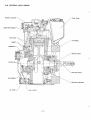
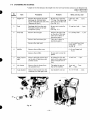
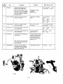
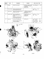
1
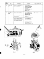
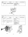
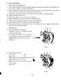
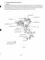
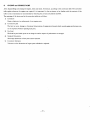
ROBIN AMERICA, INC.
ROBIN TO WISCONSIN ROBIN
ENGINE MODEL CROSS REFERENCE LIST
ROBIN
WISCONSIN ROBIN
-S
EY08
EYl5
EY 15V
EY20
EY20V
EY23
EY28
EY35
EY40
EY45V
EY2 1
EY44
EY 18-3
EY25
EY27
W 1-080
W1-145
W1-145V
Wl-185
WP-185V
Wl-230
W 1-280
W 1-340
Wl-390
W1-45OV
EY2 1W
EY44W
EY 18-3W
EY25W
EY27W
v
EHl 1
EH12
EHl5
EH17
EH2 1
EH25
EH30
EH30V
EH34
EH34V
EH43V
WOl-115
wo1-120
WO1-150
WOI-I 70
wo1-210
WO1-250
WO1-300
WO1-3OOV
WO 1-340
WO 1 -340V
WO1-430V
TWO CYCLE
EC13V
WT1-125V
DIESEL
DY23
DY27
DY3O
DY3 5
DY4 1
WRDI-230
WRD 1-270
WRDl-300
wRD1-350
WRD1-410
CONTENTS
See ti0 n
Tirle
1. SPECIFICATIONS . . . . . . . . . . . . . . . . . . . . . . . . . . . . . . . . . . . . . . . . . . . . .
2 . PERFORMANCE . . . . . . . . . . . . . . . . . . . . . . . . . . . . . . . . . . . . . . . . . . . . . .
2-1
Maximum Output . . . . . . . . . . . . . . . . . . . . . . . . . . . . . . . . . . . . . . . . .
2-2
Continuous Rated Output . . . . . . . . . . . . . . . . . . . . . . . . . . . . . . . . . . .
2-3
Maximum Torque and Fuel Consumption Ratio a t Maximum Output . . . . .
Page
1
3
3
..
3. FEATURES . . . . . . . . . . . . . . . . . . . . . . . . . . . . . . . . . . . . . . . . . . . . . . . . .
.
GENERALDESCRIPTION of ENGINECONSTRUCTION . . . . . . . . . . . . . . . . .
4-1
Crankcase . . . . . . . . . . . . . . . . . . . . . . . . . . . . . . . . . . . . . . . . . . . . . .
4-2
Crankshaft . . . . . . . . . . . . . . . . . . . . . . . . . . . . . . . . . . . . . . . . . . . . .
..................................
4-3
Connecting Rod and
Piston
4-4
Cylinder and
Cylinder
Head
..................................
4-5
Gear
Case
Cover
..........................................
4-6
Camshaft . . . . . . . . . . . . . . . . . . . . . . . . . . . . . . . . . . . . . . . . . . . . . .
4-7
Tappet
and
Tappet
Guide
....................................
4-8
Rocker Arm . . . . . . . . . . . . . . . . . . . . . . . . . . . . . . . . . . . . . . . . . . . .
4-9
Rocker Cover . . . . . . . . . . . . . . . . . . . . . . . . . . . . . . . . . . . . . . . . . . . .
4 - 1 0 Governor
System
.........................................
4 - 11 Lubrication System . . . . . . . . . . . . . . . . . . . . . . . . . . . . . . . . . . . . . . . .
4 - 12 Cooling System . . . . . . . . . . . . . . . . . . . . . . . . . . . . . . . . . . . . . . . . . .
4 - 13 Injection Pump . . . . . . . . . . . . . . . . . . . . . . . . . . . . . . . . . . . . . . . . . .
4-14 Nozzle . . . . . . . . . . . . . . . . . . . . . . . . . . . . . . . . . . . . . . . . . . . . . . . .
4 - 15 Combustion System . . . . . . . . . . . . . . . . . . . . . . . . . . . . . . . . . . . . . . .
4 - 16Sectional
View of Engine . . . . . . . . . . . . . . . . . . . . . . . . . . . . . . . . . . . .
.
5.
DISASSEMBLY and REASSEMBLY . . . . . . . . . . . . . . . . . ! . . . . . . . . . . . . . .
5- 1
Preparations and
Suggestions
.................................
5-2
Special Tools . . . . . . . . . . . . . . . . . . . . . . . . . . . . . . . . . . . . . . . . . . . .
5-3
Disassembly
Sequence
......................................
5-4
How to Reassemble . . . . . . . . . . . . . . . . . . . . . . . . . . . . . . . . . . . . . . . .
.
.
6.
.
7.
FUEL . . . . . . . . . . . . . . . . . . . . . . . . . . . . . . . . . . . . . . . . . . . . . . . . . . . . . .
6-1
Qualityof Fuel . . . . . . . . . . . . . . . . . . . . . . . . . . . . . . . . . . . . . . . . . .
GENERAL DESCRIPTION of AUXILIARY GADGETS and PARTS . . . . . . . . . .
7 .1
Fuel Injection Pump Mechanism . . . . . . . . . . . . . . . . . . . . . . . . . . . . . . .
7-2
Fuel Injection Nozzle Holder . . . . . . . . . . . . . . . . . . . . . . . . . . . . . . . . .
7-3
GovernorMechanismand
Operation . . . . . . . . . . . . . . . . . . . . . . . . . . . . .
7-4
Lubrication Systemand Oil Pump . . . . . . . . . . . . . . . . . . . . . . . . . . . . . .
7-5
Oil
Filter . . . . . . . . . . . . . . . . . . . . . . . . . . . . . . . . . . . . . . . . . . . . . . .
7-6
Electric Apparatus . . . . . . . . . . . . . . . . . . . . . . . . . . . . . . . . . . . . . . . .
INSTALLATION . . . . . . . . . . . . . . . . . . . . . . . . . . . . . . . . . . . . . . . . . . . . . .
8-1
Installing . . . . . . . . . . . . . . . . . . . . . . . . . . . . . . . . . . . . . . . . . . . . . . .
8-2
Ventilation . . . . . . . . . . . . . . . . . . . . . . . . . . . . . . . . . . . . . . . . . . . . .
8-3
Exhaust Gas
Discharge . . . . . . . . . . . . . . . . . . . . . . . . . . . . . . . . . . . . . .
8-4
Fuel
System
............................................
8-5
PowerTransmission t o DrivenMachines . . . . . . . . . . . . . . . . . . . . . . . . . .
4
8.
9.
3
3
5
5
5
6
6
6
7
7
7
7
8
8
8
9
9
9
10
11
13
13
13
14
20
28
28
.
29
29
33
36
38
38
39
40
40
40
40
40
40
.....................................
41
10. TABLE of CORRECTION STANDARDS . . . . . . . . . . . . . . . . . . . . . . . . . . . . . .
42
11. MAINTENANCE and STORING . . . . . . . . . . . . . . . . . . . . . . . . . . . . . . . . . . . .
45
11 - 1 Daily Checks andMaintenance . . . . . . . . . . . . . . . . . . . . . . . . . . . . . . . . .
45
1 1 - 2 Every 25 Hours Checksand Maintenance . . . . . . . . . . . . . . . . . . . . . . . . .
45
11 - 3 Every 50 Hours (10 days) Checksand Maintenance . . . . . . . . . . . . . . . . . . . 45
CHECKS and CORRECTIONS
--
12
.
11 -4 Every 100 200 Hours (Monthly) Checksand Maintenance . . . . . . . . . . . . .
11 -5 Every 500 600 Hours (Semiannual) Checks and Maintenance . . . . . . . . . . .
11 -6 Every 1000 Hours (Yearly) Checksand Maintenance . . . . . . . . . . . . . . . . . .
1 1 -7 Every 1500 Hours(Overhauls) . . . . . . . . . . . . . . . . . . . . . . . . . . . . . . . .
11 - 8 Preparation for LongAbeyance . . . . . . . . . . . . . . . . . . . . . . . . . . . . . . . .
45
46
46
46
46
REDUCTIONS for B TYPE ENGINES . . . . . . . . . . . . . . . . . . . . . . . . . . . . . . . .
12-1 Configuration of 1/2 Reducer . . . . . . . . . . . . . . . . . . . . . . . . . . . . . . . .
12-2 Structure of 1/2 Reducer . . . . . . . . . . . . . . . . . . . . . . . . . . . . . . . . . . . .
12-3 DisassemblyandReassembly of 1/2 Reducer . . . . . . . . . . . . . . . . . . . . . . .
47
: 48
49
51
I
b
R
X
i?
4
p?
m
I
E
E
I
W
W
X
E
E
N
a3
-
t
0
R
X
6,
?t
N
E
E
W
[D
X
E
E
W
r.
+
W
Y
.-P
v)
X
m
-
-1
-
L
W
c
L
m
c
VI
.-V
L
c
0
I
,I
I
I
I
”
I
-2-
m
-
w
2. PERFORMANCE
2-1
MAXIMUM
OUTPUT
Themaximumouput
ofan engine is suchstandardpower as developed by theengine,afterits
the moving parts properly worn in, when operating with
a fully open injection pump.
initialbreakinperiod
with all
Therefore, a new engine may not
develop the maximum output in the beginning because the moving parts are not in a properly worn-in condition.
2-2
CONTINUOUS RATED OUTPUT
The continuous rated output of an engine is such power as developed by that engine when running continuously at an optimum speed, and most favorable from the viewpoint of engine life and fuel consumption ratio, with the governor in operation. It is suggested, therefore, that when designing a driving system for any mechanism, with this engine as prime mover,
the continuous power requirement of that mechanism be kept below the continuous rated output specified.
2-3
MAXIMUM TORQUE and FUEL CONSUMPTION RATIO AT MAXIMUM OUTPUT
These mean the maximum torque of the output shaft andfuel consumption ratio at the maximum output of an engine,
PERFORMANCE CURVE
MODEL DYBOD, B
10
kg-m
HP
tI
9
2
8
1.5
7
1
t
6
5
4
3
JIHP-h
2
1
1c
-
( 1 450)
rpm.
-3-
(1
-
PERFORMANCE CURVE
MODEL DY35DtB
10
,
-
I
M A X . TORQUE
9-
8-
7-
rv
6-
5-
4-
3-
-
PERFORMANCE CURVE
MODEL DY41D, B
HP
g/H P- h
LIGWWEIGWTand COMPACT
1 . Lightweight because of aluminum alloy being usedfor various parts including the crankcase madeof aluminum die casting
2. Compact in outside dimensionsbecause-
is reduced,
a) the camshaft is assembled inside of the gear case cover, and accordingly total width of the engine
b) the cooling fan and theflywheel are single piece die casting; and the cooling fanis set on the side of the case so that it
may breathe in cooling
air from the front, whichmeans that the size of the fancasing becomes smaller andtotal length
of the engine is also reduced.
FUEL ECONOMY and NOISELESS TYPE ENGINE
Low fuel consumption owing to improved fuel combustion systemhaving adopted direct fuel injection; andnoiseless opera-
tion owing to the highly effective muffler and air cleaner
As an optional part abalancer is available for minimizing vibration.
EASY to TAKE-OUT POWER
A faucet joint is set in the blower housing, which enables direct coupling with a machine. P.T.O. shaft is connected to the
flywheel and accordingly this engine is very easy to handle. Furthermore, as cooling air is taken into from the front of case
(reverse side of the machine coupled), itis unnecessary to arrange air-intakeon the side of the machine. Therefore, itis easy
to couple a machme to the engine.
4. GENERAL DESCRIPTION of ENGlME CONSTRUCTION
This engine is a Forced Air Cooled, 4-Cycle, Vertical, Single Cylinder, Overhead Valve Diesel Engine, and the combustion
system is direct injection type.
4 - 1 CRANKCASE
The crankcase is made of a one-piece aluminum alloy
die
1
casting. On the side of pump, bearing is press-fitted; and on
I
the fan side cast iron bearing housing is arranged, and it supports the crankshaft by a
ball bearingpress-fitted to the
I
shaft. Also, on the fan side, blower housing of aluminum
.
die casting is fitted. This blower housing has a faucet joint
and it enables direct coupling with a machine. (See Fig. 1.>
Fig. 1
-5-
-
-
4-2 CRANKSHAFT
The crankshaft is made of a forged chrome and molybdic
steel piece with the crank pins and the journals ground t o
high precision after induction hardening. It is fitted to the
flywheel on the fan side, and connection of the drive shaft
to it is also possible. In the center of the pins and the journals, holes for forced lubrication aredrilled through.
(See Fig. 2.)
Fig. 2
4-3 CONNECTING ROD and PISTON
4 - 3 - 1 CONNECTING ROD
The connecting rod is made of forged pieces of aluminum
alloy designed with sufficient strength to withstand buckling
and tensile forces inflicted on it under high-load operating
conditions. At the small end a bushing is forcefitted to withstand the pressure resultant from pitching duringhigh-speed
operation. At the larger end thin kelmetis fitted for increasing durability.
4 - 3 - 2 PISTON
Piston is made of cast aluminum alloy, and it has two compression rings and an oil ring.Combustion chamber arranged
at the pistion head,
Fig. 3
where combustion gas is made up by
mixing atomized fuel and air, andignites. (See Fig. 3.)
4-4
CYLINDER and CYLiNDERHEAD
4-4-1 CYLINDER
Cylinder is made of aluminum alloy die casting, in which
special cast iron liner is cast, andis provided with many cooling fins designed for effective cooling.
4 - 4 - 2 CYLINDERHEAD
The most important part
of the diesel engine is cylinderhead.
It is a one-piece of aluminum alloy die casting, in which intake and exhaust ports, and rocker chamber are cast in the
most ideal structure for the highest strength and the highest cooling efficiency. In thevalve seats fine quahty heat resistance seats are pressure-fitted considering high resistance
to abrasionandcorrosionat
high temperature. (See Fig. 4.)
-
-6-
Fig. 4
4-5 GEARCASECOVER
Gearcase cover is made of aluminum alloy die casting and is
fitted on the
reverse side of the flywheel. This cover em-
braces the injection pump, timing gear, operating lever and
supports the camshaft as a bearing. To the gear case cover
the tappet guide is fitted and then the tappets
are assembled,
(See Fig. 5 .)
Fig. 5
4-6
CAMSHAFT
The camshaftis made of forged chrome steel wholly sintered
and then ground. It carries three cams, viz. one intake cam,
one exhaust cam, and one fuel injection pump cam, and the
shaft is supported by a
ball bearing pressure-fitted in the
i
gear case cover and by the gear case. The camshaft is assem
bled inside the gear case cover. To the shaft therelief valve
and a pin are fitted. The pin is used when starting engine by
hand cranking. (See Fig. 6.)
4-7
TAPPET and TAPPET GUIDE
4 - 7 - 1 TAPPET
Tappet is made of forged steel and wholly sintered, ground,
and then taftride finished. The camshaft
has oil holes for
lubricating tappets.
4-7-2TAPPET GUIDE
Tappet guide is made of aluminum alloy die casting and determines tappet positionsandis fitted to the gear case cover.
Fig. 6
In the crankcase there is a blow-bygas hole, which hole goes
through up till rocker chamber via push rod sleeve.
(See Fig. 6.)
4-8
ROCKER A R M
Rocker arm is made of forged steel and is wholly sintered and then ground, and itis supported by the rocker shaft. At the
one end it has valve clearance adjusting screw. With this screw valve clearance is adjusted to the specified gap and is fixed by
lock nut. Lubrication of the rocker arm is carried out by theoil splash contained in the blow-by gas from the crankcase. Intake rocker arm has decompression mechanism. (See Fig. 6.)
-7-
4 - 9 ROCKER COWER
Rocker cover is made of aluminum ailoy die casting and it
is fitted to the cylinderhead and covers the rocker chamber.
Rocker cover has a breather; and theair breathed is brought
to the intake port.
(See Fig. 7.)
Fig. 7
.
.-
!
4-10 GOVERNOR SYSTEM
The governor is a centrifugal flyweight type and is installed
’
on the governor gear. Through the lever it adjusts the rack
:
of fuel injection pump and keeps constant operation at the
1
selected speed against load variations.
(See Fig. 8.)
Fig. 8
4- I f LUBRICATION SYSTEM
Lubrication is wholly filtered and pressurized lubrication
system by trochoid type
oil pump. From the main gallery
in the crankcase the pressurized oil runs through the crank
journals and crankpins, and from the larger part of the rod
the oil is supplied in the form of splash to the parts necessary to be lubricated, while part of the oil also runs through
the bearings of camshaft
to lubricate both intake and ex-
haust cams, and tappets. Ths system includes the governor
gears and it is installed in the crankcase.
(See Fig. 9.)
fig. 9
-8-
CYLINDER BAFFLE
4-12 COOLING SYSTEM
The cooling fan and the flywheel
are a single piece casting
and it is fitted to the top end of the crankshaft. Cooling air
produced by this fan blows through blower housing and cylinder baffle, andcools cylinder and cylinderhead.
(See Fig. lo.)
Fig. 70
4-13 INJECTION PUMP
The plunger of the fuel injection pump is operated by the
injection pump cam, and the fuel from the tank is pressur-
ized in the pump and supplied
to the nozzle via the high
pressure pipe.
(See Fig. 11.)
U
Fig. 1 1
4-14 NOZZLE
Into the combustion chamber thenozzle injects the pressurized fuel supplied from the pump through the high pressure
pipe.
(See Fig. 12.)
Fig. 12
-9-
4-15 COMBUSTION SYSTEM
/INTAKE
For lower fuel consumption and easy starting of the engine,
the direct injection system is adopted in the combusition
VALVE
INTAKE PORT
chamber.
4-15-1 FORMING of COMBUSTION GAS and COMBUS-
SWIRL
TION
CYLINDER
SWIRL (Inspiring swirl)
In order to promote
mixing injected fuel andair under
the direct injection system,
PISTON
swirl flow is utilized for
good Combustion. Swirl is spiral flow of air generated
in the cylinder duringinspiring stroke, and itdecreases
during compressing stroke but it still remains and promotes mixing of fuel and air toward ignition timing.
Spiral flow of air (swirl) is generated by the shape of
intake port, which is called helical port or spiral port.
Fig. 13
Tail end of intake port,i.e. upper part of intakevalve
seat, is madein the spiral form; andwhile the inspired
air is passing throughthispart,
swirl is generated
around the intakevalve. Thus, intake portplays an important role in generating swirl. (See Fig. 13.)
SQUISH (Squished air flow)
In the piston, combustion chamber (dish type combustion chamber) is formed. When the piston comes
gaps is squished
up toTDC (top dead center), air in the
in the combustion chamber and air flow is generated,
which is called “squish.” (See Fig. 14.)
Fig. 14
FORMING of COMBUSTION GAS and COMBUSTION
For igniting quickly the fuel injected from the nozzle, it is essential to atomize very fine oil particles for distributing
evenly in the combustion chamber. For t h s purpose, fuel should be injected through hole type nozzle
by very high
pressure, i. e. 195 kg/cm2. The fue!, thus injected, is mixed with air by the flow of swirl and squish while piston is
Coming Up. Accompanying crimb of the piston, combustiongas compressed further and finally it automatically begins
igniting and while piston is going down, “squish” functions and promotes combustion.
- 10 -
4-16 SECTIONAL VIEW of ENGINE
- 11 -
EXHAUST VALVE
CYLINDER HEAD-\
ROCKER COVER
INTAKE VALVE
\ \
AIR CLEANER
CY L
BA
O I L PAN-’
- 12
-
5. DISASSEMBLY and REASSEMBLY
5-1
PREPARATIONS and SUGGESTIONS
1) When disassembling the engine, remember well the locations of individual parts so that they can be reassembled cor-
rectly. If you are uncertain of identifying some parts, itis suggested that tags should be attached to them.
2 ) Have boxes ready to keep disassembled parts by group.
3) To prevent missing and misplacing, temporarily assemble as much as possible each group or set of disassembled small
parts such as bolts and nuts, etc.
4) Carefully handle disassembled parts, and clean them with washing oil.
5)
Use the correct tools in the correct way.
5-2 SPECIAL TOOLS
I
I
I
Tool No.
228 95001 07
22895002 07
228 95003 07
I
1
I
I
Tool
Use
Flywheel puller with bolt
For pulling off the flywheel
Box wrench
For removing or fastening the
flywheel nut
I
Piston ring expander
/
For placing piston ring
PISTON RING EXPANDER
\ B O X WRENCH
Fig. 15
- 13 -
I
I
,-
b
5-3 DISASSEMBLING SEQUENCE
*Length of the bolt indicates the length from the bolthead bottom surface to the threaded end.
* * SW + Spring water
* **W + Plain washer
Sequence
Item
~~~~~~~
Procedures
~
~~~
~
~
~~~
Remarks
-
~
~~~
~
Bolts, nuts etc. used
~~
1
Engine oil
Remove the oil drain plug and
discharge oil. Oil drain plug
locates under the gearcase cover.
(Remove oil filter.)
Be sure not to miss the
“0” ring. The drain plug
serves as anoil fiIter too.
(See Fig. 16.)
6 mrn hex. bolt . . . 2 pcs.
SW . . . 2 pcs.
2
Fuel
Discharge fuel from the tank.
Fuel pipe locateson the side
of injection pump.
Be sure not to miss the
gasket.
(See Fig. 17.)
17 mm hex. bolt. . . 1 pce.
3
Fuel tank
Remove the fuel pipe.
Remove the banjo bolt
on theside of the tank.
There are 2 sheets of
aluminum gasket.
There are2 sheets of
aluminum gasket.
8 x 18 banjo bolt . . . 1 pce.
I
~
Remove the fuel returnpipe.
4
5
Muffler
High pressure
Pipe
Remove the tankband.
6 x 45 round head cross
recess bolt . . . 2 pcs.
No SW,W
Remove the mufflercover.
6 x X mm flange bolt
. . . 4 pcs.
Remove the muffler.
Be sure not to miss the
gasket.
Remove the high pressure pipe
on the sideof injection pump
and the nozzle.
Be careful to keep the
inside of the pipe, pump,
joint of nozzle free of
dust.
12 mm n u t . . . 2 pcs.
6
Air cleaner
Remove the air cleaner from
the cylinder head.
The gasket is same as
that of the muffler.
8 mm n u t . . . 2 pcs.
sw . . . 2 pcs.
7
Tank bracket
Remove the bracket from the
crankcase, left and right, each.
Just loosen 8 mm nut.
8 x 16 7T b o l t . . . 2 pcs.
Fig. 16
Fig. 17
-14-
Sequence
Fly wheel
8
9
Bolts, nuts etc. used Remarks
Procedures
Item
Remove the flywheel cover.
Remove the driving shaft.
Raise up lock washer, loosen
lock nut (41 mm box spanner)
and then remove the flywheel
from the crankshaft using the
flywheel puller.
Crankshaft, normal
threading
(See Fig. 18.)
Blower housing Remove the blower housing
from the crankcase.
Just loosen theflange
bolts.
CylinderbaffleRemove
the cylinderbaffle
from the cylinder.
Be sure not t o miss
5 mm nut.
~~
10
l3
14
I
Rocker cover
Remove the rocker cover from
the cylinderhead.
Nozzle holder
Remove the nozzle holder from
the cylinderhead.
Rocker arm
Cylinderhead
I
~~
6 x 8 flange bolt . . . 2 pcs.
N o W.
8 x 5 5 7T b o l t . . . 2 pcs.
sw . . . 2 pcs.
8 x 40 7T bolt. . . 2 pcs.
sw . . . 2 pcs.
~
~~
~~
~~
5 x 10 round head cross
recess screw . . . 1 pce.
6 x 35 7T bolt. . . 3 pcs.
sw . . . 3 pcs.
At the top end the
gasket is fitted.
6 mm n u t . . . 2 pcs.
sw . . . 2 pcs.
Loosen thenuts fastening theLoosenthetappetadjustcylinderhead.
and
ing bolt
the decompression adjusting bolt,
which latter is on the
side of the intake valve.
(See Fig. 19.)
Pull out the rocker shaft from
the cylinderhead and remove
the rocker arm.
Just loosen 6 mm nut.
Loosen 6 mm nut which is
fastening the push rodsleeve
on the side of cylinderhead.
Pull out the push rod.
Fig. 78
- 15
-
6 mm n u t . . . 2 pcs.
l"2L
I
Procedures
Remarks
I
Bolts, nuts etc. used
quence
l5
Remove the cylinder.
are rubber "0" ring and
copper shim.
(See Fig. 20.)
ICylrnder
6 mm nut . . . 2 pcs.
sw . . . 2 pcs.
Remove the push rodsleeve
from the gear case cover.
17
Tappet guide
Remove the tappet guide from
the gear case cover.
A holder is necessary for
not let fall the tappet.
(See Fig. 2 1 .)
18
Injection
pump
Remove oil filler cap.
Put the control rack at the
center.
Remove the injection pump
from the gear case cover.
Check the position of
control
rack.
(See Fig. 22.)
8 mm nut . . . 3 pcs.
sw . . . 3 pcs.
19
Gear
case
Remove the handleguide.
(See Fig. 23.)
6 x 6 hex. bolt . . . 2 pcs.
sw . . . 2 pcs.
8 x 35 7T b o l t . . . 4 pcs.
8 x 80 7T bolt. . . 3 pcs.
sw . . . 3 pcs.
Remove the gear case cover
from the crankcase.
It
b
/.".c.
. r-
.P
/"
Fig. 20
\ -
Fig. 22
Fig. 23
Procedures
Remarks
20
Camshaft
Pull
camshaft.
theout
Between
camshaft
and
gear case there is a shim.
(See Fig. 24.)
21
Piston
Remove the piston from the
connecting rod. (Remove the
clip and pull out the piston.)
Watch the direction of
the clip, also pay attention t o the direction of
the piston.
(
mark indicates "toward the fan side.")
(See Fig. 25.)
Bolts,
etc.
nuts
used
"f
22
Governor and
oil pump
From the crankcase remove
the governor and oil pump in
the form of one piece.
23
Oil pan
Remove
the oil pan
from
crankcase.
6 x 20 7T bolt
sw . . . 2 pcs.
Be careful of the packings.
the
. . . 2 pcs.
6 x 12 bolt . . . 8 pcs.
sw . . . 8 pcs.
/"-
Fig. 25
Fig. 24
- 17
-
Setuence
Item
Procedures
Remarks
Bolts, nuts etc. used
I
_
24
Connecting
rod
Remove the connecting rod
from the crankshaft.
No lock washer.
Be careful of the direction of rod. (Fan mark
is on the sideof the
flywheel.)
Be careful of the setting
mark of the cap.
(See Fig. 26.)
25
Bearing housing and crankshaft
From the crankshaftremove
the key on the side
of fan.
Be careful of the copper
shim and “0” ring between the bearing housing and thecase.
Remove the bolt fastening the
bearing housing.
Also be careful of the
hole for oil.
Pull the crankshaft together
with the bearing housing.
(Gently tap the sideof crank
gear with plastic hammer.)
After pulling out the
crankshaft from the
case, remove housing.
8 x 22 7T bolt.
SW . . . 6 pcs.
The bearing remains on
the crankshaft.
(See Figs. 27, 28 and 29.)
Fig. 27
Fig. 26
Fig. 28
-18-
. . 6 pcs.
1
Fj
quence
1
1
T
Item
Intake and
exhaust valve
I
Procedures
Remarks
Remove the intake and exhaust
valves from the cylinderhead.
I
Bolts, nuts ~Pc.used
On theside of intake
valve, there is a stem
seal. Be sure not to miss
retainer lock.
(See Fig. 30.)
J
Fig. 30
Se-
I tem
Procedures
Remarks
Snap ring
Remove the snap ring.
Be sure not to miss the
snap ring.
(See Fig. 3 1 .)
2
Balancer shaft
Remove the balancer shaft.
Gently tap with plastic
hammer.
3
Balancer
Remove the balancer from
the case.
Be careful not to damage
the thrust metal on the
side of the pump.
The gear and the needle
bearing are in one piece.
(See Fig. 32.)
Bolts, nuts etc. used
/“-
Fig. 31
Fig. 32
-19-
5-4 HOW TOREASSEMBLE
1.
PRECAUTION I N REASSEMBLING
1) Every and each part should be cleaned thoroughly. Easpecially, pay utmost care and attention to the cleanliness of the
piston, cylinder, crankshaft, connecting rod and bearings.
2) Scrape completely off carbons from the cylinder head and the upper partof the piston; especially the carbon adhered
in the groove of the piston ring should be carefully and completely takenout.
3) Carefully check the lip portion of every oil seal. If faulty one is found, replace it without slight hesitation.
4) Replace all the gaskets with new ones.
5 ) Replace the key, pin, bolt, nuts, etc. with new one, if necessary.
6 ) Whenever tightening torque is specified, conform to the specified figures.
7)
Apply oil to the revolutionary parts and friction surfaces, when reassembling.
8) Check and cidjust the clearances of variouts portions and then reassemble.
9) When some main Grtions are assembled in the course of reassembling, turn or move the gadgets by hand and pay attntion to the frictional
noise and resistance.
2.
1)
REASSEMBLING
Insert the crankshaft into the crankcase.
CAUTION: Be careful not t o damagebearingmetal
on the side of injection pipe.
For the engine with the balancer, fit the balancer first
it into the crankcase.
to the crankshaft, and then put
CAUTION: When fitting, check the match mark.
(See Fig. 33.)
Fig. 33
2) Assemble the bearing housing.
8 x 22 7T bolt
............
Springwasher
. . . . . . . . . . . . 6 pcs.
6 pcs.
NOTE: Apply oil or grease inside the housing oil seal.
CAUTION: Be sure to put "0" ring on.
NOTE: Set the bearing
housing
so that its oil hole
-q
may face upward.
3
(See Fig. 34.)
Fig. 34
- 20 -
:-
NOTE: With
thecoppershimadjust
ance of the crankshaft be 0.1
- 0.2
the side clearmm.
Three kinds of shim are available, viz.0.1 mm, 0.2 mm,
and 0.3 mm thick.
[Tightening toruque: 200
-
230 kg-cm]
(See Fig. 35.)
Fig. 35
3 ) Assemble the connecting rod.
CAUTION: Pay attention to the directionof the rod.
(FAN mark is to be set on the side of the flywheel.)
NOTE: Check the match mark on the cap.
NOTE: The lock washer is not usedwhenfastening
the bolt. [Tightening torque: 250
-
270 kg-cml
(See Fig. 36.)
Fig. 36
4) Assemble the oil pan.
6 x 12 bolt . . . . . . . . . . . . . . 8 pcs.
Springwasher
. . . . . . . . . . . . 8 pcs.
NOTE: Pay attention to the packings.
(See Fig. 37.)
Fig. 37
- 21
-
u
Assemble the piston.
MOTE: + mark in the upper part of the piston is to
be faced to the fanside.
MOTE: Piston rings are not assembled.
MOTE: Shape of the piston pin.is (D
.
(See Fig. 38 .)
Assemble the cylinder
NOTE: Insert thepiston
into thecylinder(piston
ring is not inserted.), and measure the dimensions of
the head of piston and upper surface of the cylinder.
NOTE: The concave dimensions of the pistion is -0.6
-
Fig. 38
-0.7 mm from the upper Surface of the Piston.
MOTE: Adjustment of the concavedimensions is to be made by the shim underneath the cylinder, and available thickness of the shim are 0.1 mm and 0.2mm.
MOTE: Fit the piston rings on the piston.
Punched mark "N" are to be faced up. Open end of each ring must avoid the direction toward the thrust
side and it is
to be set to the different three directions.
NOTE: Set the cylinder.
Be sure to fit rubber "0" ring and shim.
Notched portion of the cylinder skirt must be set on the side of the gear case cover. (See Figs. 39-1 and 39-2.)
TOP R I N G
D
SECOND R I N G
I
OIL RING
23
1
Fig. 39- 7
Fig. 39-2
7 ) Install the flywheel.
'
(Use 41 m m box wrench.)
NOTE: When puttinglock
bend the tabs securely.
[Tightening torque: 2,000
washerson,besure
- 2,200
to
kg-cml
(See Fig. 40.)
f i g . 40
- 22 -
8)
Installthecamshaft.
NOTE: Apply oil or grease to the inside of oit seal for t h e gear case cover.
NOTE: Set the match mark of the camshaft so as to fit to t h a t of the crank gear. Side clearance is to be adjusted to
0.1
-
0.3 mm. Three kinds of shim are available, viz. 0.8 mm, 1.O mm and 1.2 mm.
Fig. 42
Fig. 41
9) Assemble the oil pump and the governor.
6 x 2 0 7 T b o l t . . . . . . . . . . . . 2 pcs.
Spring washer . . . . . . . . . . . . 2 pcs.
NOTE: Thehole
in the oil pump coveris
to face
downward.
NOTE: Check if the governorsleeve moves smoothly.
Outer surfaceof t h e trochoid pump must face the
case
side. (See Fig. 43.)
[Tightening torque: 80
-
100 kg-crn]
\
the
10)
Assemble
Fig. 43
gear case cover.
8 x 5 7T bolt,
...,........
Springwasher
. . . . . . . . . . . . 4 pcs.
4 pcs.
NOTE: When the pin is replaced, apply "Three Bond" at the both ends of the pin for cranking. This pin locates a t t h e
top of the camshaft.
8 x 65 7T bolt. . . . . . . . . . . . 3 pcs.
Spring washer . . . . . . . . . . . . 3 pcs.
NOTE: Check if the governor link operates.
[Tightening torque: 200
- 230
kg-cm]
- 23
-
r
Assemble the injection pump.
8 mm nut
. . . . . . . . . . . . . . . 3 pcs.
Springwasher
. . . . . . . . . . . . 3 pcs.
NOTE: Measure the distance between the face of the cam base and the surface to which the injection pump is to be
fitted. And adjust it may become 76 k 0.05 mm, usingthe shims. Two kindsof t h e shim are available, viz. 0.1 mm, and
0.3 mm.
CAUTION: Remove the oil filler cap and check if the control rack comes off from the governor lever.
(See Figs. 44 and 45 .)
-
. .-
___
l._l
"
I
~
."
,
,
-
Fig. 45
Assembe the tappet guide.
CAUTION: Be careful not l e t the tappet fall i n the
case.
NOTE: The roll pin of the tappet guide is to be set
a t the right side as viewed from the gear case side.
(See Fig. 46.)
Fig. 46
13) Temporarily assemble the push rod
sleeve.
6 mm nut . . . . . . . . . . . . . . . 2 pcs.
Springwasher
. . . . . . . . . . . . 2 pcs.
NOTE: 2 pcs. of the plate (push rod sleeve) are to be assembled temporarily.
- 24 -
a
Assemble the cylinderhead.
10 mrn flange nut . . . . . . . . . . 4 pcs.
Washer
NOTE:
.................
4 pcs.
Install the intake and exhaust valves. On the
intake side there i s a stem seal.
NOTE: Insert
the push rod. (Exhaust is on the side
of the gear case.) Pay attention to the valve facing, UPwardordownward,and
direction of intake and ex-
haust.
NOTE: Install the rocker arm to the cylinder.
It is advisable to insert the rocker shaft before clamp-
ing the head.
Fig. 47
(See Fig. 47 .)
NOTE: Clamp the head to the cylinder.
Apply "Three Bond #
21I
5" to twopieces of the stud
bolt (on the side of the rocker shaft) and upper and
reverse surfaces of the washer, and then tighten the
nuts.
[Tightening torque: 350 kg-cm]
.
Tightening of the nuts is to be done in three rounds,
I.
e.:
. . . . . . . . . . . . . . . 100 kg-cm
2nd round . . . . . . . . . . . . . . . 200 kg-crn
3rd round . . . . . . . . . . . . . . . 330 350 kgcm
1s t round
-
NOTE: Fasten
6 mm nut
I
tightly the plate (push rod sleeve).
. . . . . . . . . . . . . . . 4 pcs.
(See Fig. 48.)
15)
Adjust the valve clearance.
NOTE: Turn the flywheel by
hand
to the compres-
sion a t TDC (top dead center). At TDC the camshaft
DECOMPRESSiON \,
ADJUSTING SCREW
cranking pin stands vertically.
NOTE: Adjustthe valve clearance to anywherebetween 0.07
-
0.10 mm (both intake and exhaust),
when the engine is cold.
(See Fig. 49.)
Fig. 49
- 25 -
TDC (TOP DEAD CENTER)
INTAKE, EXHAUST VALVE TIMING
When valve clearance
INTAKE VALV
is a t 0.4 mm and the engine is
heated,
intake valve opens a t 16O before TDC,
intake valve closes a t 54' after BDC,
exhaust valve opens a t 54' before BDC, and
exhuast valve closes a t 14" after TDC.
(See Fig. 50.)
AUST
VALV
VALVE
INTAKE
BDC (BOTTOM DEAD CENTER)
Adjust the decompression clearance.
Fig. 50
NOTE: The decompression device locates in the rocker arm on the intake valve side.
NOTE: Set the decompression lever at the position of decompression. (Push the lever to the horizontal position.)
NOTE: Clearance is about 0.5 mm. Turn the adjust screw until it touches the decompression shaft, and then make
another half turn. Threading of this screw is 1 .O mm.
Turn the flywheel by hand and check a contact between thevalve and the piston.
Assemble the rocker cover.
6 x 3 5 7 T b o l t . . . . . . . . . . . . 3pcs.
Springwasher
. . . . . . . . . . . . 3 pcs.
NOTE: Check if there is an "0" ring for breather hole on the surface of the head (intake breather's side).
NOTE: Check if the gasket for the rocker cover is put correctly in the groove.
Install the nozzle holder.
6 mm nut . . . . . . . . . . . . . . . 2 pcs.
Springwasher
............
2 pcs.
NOTE: Pay attention to the gasket at the top. It is advisable t o utilize the driver foreasy installation.
[Tightening torque: 90
-
100 k g - c m l
Install the blower housing.
Upper part: 8 x 55 7T bolt . . . 2 pcs.
Springwasher
Lower part: 8 x 40 7T bolt
. . . . 2 pcs.
. . . 2 pcs.
Springwasher . . . . 2 pcs.
Install the driving shaft.
10 x 30 bolt
. . . . . . . . . . . . . 4 pcs.
Assemble the flywheel cover.
8 x 16 bolt . . . . . . . . . . . . . . 4 pcs.
Assemble the cylinder baffle.
6 x 8 flange bolt . . . . . . . . . . . 2 pcs.
5 x 75 round head cross recess
bolt and nut 5 mm
.........
1 pce. each
Fig. 51
(See Fig. 5 1.)
26 -
Install the tank brackets, left
and right.
8 x 16 7T bolt . . . . . . . . . . . . 2 PCS.
. . . . . . . . . . . . 2pcs.
8 mm nut bolt . . . . . . . . . . . . 2 pcs. each
Springwasher
Connect the fuel pipe and fuel return pipe securely.
. . . . . . . . . . 2 pcs.
Aluminum packing . . . . . . . . . 2 pcs.
8 x 18 banjo bolt
NOTE: Connect the pipe t o the nozzle first, and then connect the fuel pipe t o the tank.
Install the air cleaner.
8 mm nut
. . . . . . . . . . . . . . .2 pcs.
Springwasher
. . . . . . . . . . . . 2 pcs.
NOTE: Pay attention to the gasket.
Install the muffler and the muffler cover.
Muffler: 8 mm brass nut . . . . . 2 pcs.
Spring washer . . . . . . . 2 pcs.
Muffler cover: 6 x 8 flang bolt.
.
4 pcs.
NOTE: Pay attention to t h e gasket.
I.-
Connect the high pressure pipe. (See Fig. 52.)
It is advisable to remove the cap of the air cleaner and
then connect.
Mount the fuel tank.
6 x 45 round head cross recess
screw . . . . . . . . . . . . . . . . . . 2 pcs.
When installing t h e fuel filter once removed from the
tank, fasten the filter by hand and then make 1/4 turn
with a spanner.
Install the oil filter
6 x 12 bolt . . . . . . . . . . . . . . 2 pcs.
Springwasher
............
2 pcs.
The oil filter serves as the oil drain plug too.
Be sure t o install "0"ring.
Install the handle guide.
. . . . . . . . . . . . . . 2 pcs.
Springwasher . . . . . . . . . . . . 2pcs.
6 x 12 bolt
Supply engine oil.
Upper level
..............
1 .O R max.
Fig. 52
Lower level . . . . . . . . . . . . . . 0.6 II min.
Also pour oil into the air cleaner, watching oil level.
Supply diesel light oil.
Fuel tank capacity
. . . . . . . . . 4.5 R
- 27 -
6. FUEL
0-1 QUALITY Of FUEL
Because of the high speed diesel engine, be sure to use the good quality diesel light oil. If improper fuel is used, the injection
pump, nozzle,and piston develop troubles. (See Fig. 53.)
i
F U E L R E T U R N PIPE
f
T
\
/
AIR RELEASE
fUEL
TANK
NOZZLE
/
\
"
FUEL F I L T E R
HIGH PRESSURE PIPE
F U E L PIPE
FUEL INJECTION PUMP
FILTER
T A NPRESSURE
K
PUMP
t
PIPE
PIPE
FUEL RETURN
PIPE
Fig. 53
- 28 -
PIPE
7. GENERAL DESCRIPTION of AUXILIARY GADGETS and PARTS
7-1
FUEL INJECTION PUMP MECHANISM
It is not too much tosay that the fuel injection pumpis the heart of thediesel engine, and it must beprecise enough t o satisfy the following functions.
Function
Injecting fuel, starting withhigh pressure and ending with low pressure.
Injecting the predetermined amount of fuel accurately at each stroke.
Injecting fuel at specified time within a specified time interval.
Quantity being injected is closely vaned by thegovernor to suit to varying load.
This engine has no automatic advancing device,but in starting (max.delivery), the injection timeingis to be delayed.
Theory of the injection pump mechanism
The plunger of the injection pumpis pushed u p by the cam of the camshaft, and itis pushed down by the plunger spring. By
this up and down motion in a stroke, suction and forced supply
of fuel are conducted. (See Fig. 54.)
Suction of fuel
Through the filter in the fuel tank, fuel is supplied and is in full around the intake port of the plunger barrel. When
the top of the cam lobe passed the tappet and cam function ended,
plunger spring pushes down the plunger.
When the plunger is pushed down passing the fuel intake, fuelis sucked into the barrel, and suctionis continued until
This is on the stage of "suction."
arrival of the plunger at the bottom of its stroke.
Forced supply of fuel.
The camshaft rotates and pushes up the plunger. Forced supply of the fuel is started only when the upper partof the
plunger closed the fuel intake in the course of being pushed up by the cam rotation. The fuel in the barrel is pressurized by a,very strong force (100 kg/cm2 and up), andas a result, the force of thefuel pushes up the delivery valve and
the damping valve, and then it injects thefuel into combustion chamber.This is on the stage of "pressurized supply."
DAMPING VALVE
DELIVERY VALVE
V E R T I C A L HOLE
PLUNGER BARREL
PLUNGER
I N T A K E PORT
(EXHAUST PORT)
LEAD
EFFECTIVE STROKE
Fig. 54
- 29 -
3.
Variation in quantity of fuel to be injected
The quantity of fuel injected vanes according to the condition of the engine, i. e. high speed or low speed operation and
loaded or unloaded operation.(See Figs. 55 and 56.)
The plunger lead is engraved on the surface of plunger in an inclined curve. By rotating the plunger, the distance between
the upper part of the plunger and the suction portis varied. (Variation in effective stroke)
Rotation of the plunger is made by the control rack.When this control rack is shifted to left and/or right, thegeared pinion
rotates, which is connected to theplunger by means of the controlsleeve. In other words, theplunger turns as much amount
as the rack rotates. Accordingly, the effective strokevaries coincident with the positionwhere the rack is set.
1) Relation between the plunger and the barrel
EFFECTIVE STROKE
PLUNGER BARREL
I N T A K E E X H A U S T PORT
INJECTION
INJECTION
INJECTION
INJECTION
ENDS.
STARTS.
ENDS.
MAX. DELIVERY
STARTS.
HALF DELIVERY
NO DELIVERY
Fig. 55
2)
Relation between the plunger and the rack
CONTROL SLEEVE
MAX. DELIVERY
HALF D E L I V E R Y
Fig. 56
- 30 -
NO DELIVERY
4.
Injection timing andeffectivestarting
When the plunger closes suction port of the barrel, forced
delivery of fuel starts.But fuel is not injected from the noz2le.at ence because of contraction of,fuel,'etc.
.
Injection timing of this engine is fixed constant ( 2 3 O before
TDC) irrespective of engine rpm.On the other hand,in starting, a proper delay from the timing for high speed running
andincreasedfuelinjection
INSTALLED ONLY TO D Y 3 0
is indispensable for effective
starting. For this purpose a notch is made at the plunger
Fig. 57
head, w h c h reserves to delay the injection timing by nearly
8" to facilitate starting. (See Fig. 57.)
5.
Function of the delivery valve
By the plunger stroke, fuel pressure is raised. And when it becomes higher than the pressure remained in the high pressure
pipe, the deliveryvalve spring is pushed down and the valve opens. As the result, thefuel in the high pressure pipe is delivered
forcibly.When theplunger lead meets suction port of the plunger barrel, deliveryof fuel ends, and thedelivery valve is closed
by the spring tension of the valve. At this time, delivery valve prevents reverse flow of the fuel. Also suction back motion
around the upper part of the plunger sucks back the fuel in the equal amount of the stroke [A] and
decreases remaining
pressure in the high pressure pipe. The nozzlejets the fuel clearly off and prevents after dripping.(See Fig. 58.)
!I!
/ DELIVERY
VALVE
SPRING
DELIVERY VALVE
ION BACK STROKE
Fig. 58
6.
Function of the damping valve
Thedamping
valveis
assembled in theend
of injection
pump and it reaches the seat before arrival of delivery valve
at the seat. The small orifice in the valve is the passage of
fuel t o the chamber in the delivery valve holder. Accordhgly, descendingvelocityof
whichprevents
DAMPING VALVE
the delivery valve is decreased,
the negativepressurebeingproduced
denly. As aresult,properinjection
sud-
is conductedandthe
DEL,VERY VALVE
engine noise is decreased. (See Fig. 59.)
Fig. 59
- 31
-
0 FUEL INJECTIONPUMP
VALVE
DAMPING
VALVE
DAMPING
SPRING
DELIVERY VALVE
DELIVERY VALVE
BOLT
SEMBLY
RELEASE
AIR
PUMP HOUSING
DELIVERY VALVE
-
PLUNGER
RACK
CONTROL
STOP
CONTROL SLEEVE
PLUNGER SPRING
SPRING SEAT
PIN
Fig. 60
0 SPECIFICATIONS of FUEL INJECTION PUMP for THIS DIESEL ENGINE
Model
PFRIKD55/2NP1
Maker
Diesel Kiki K.K.
5.5 mm
Plunger diameter
Lead
Right twist lead
Plunger spring arbitrary
2.46 kg/cm
Delivery valve opening pressure
27.5 kg/cm2
Delivery valve spring constant
0.51 kg/mm
Pump rack friction load
0.062 kg
Rack stroke
16 mm
-32 -
7-2
1.
FUEL INJECTION NOZZLE HOLDER
Specifications
~
~~
Part Name
I
I
NOZZLE HOLDER
Part No.
105 11840 00
Identification mark
C
No. of nozzle hole
4
(Diameter)
(0.22mm)
Valve opening pressure
195 kg/cm2
Spring constant
13.2 kg/cm2
a
2.
Features
Both the injection nozzle and the injection pump are very important parts for producing fuelfog for combustion. There are
two types of injection nozzle, one is hole type and the otheris pintle type. The injection nozzle for DY30 and DY35Diesel
engine is developed as a result of joint research and development project by Diesel Kiki, K. K. and our company, and it is
direct combustion system,having the special hole type nozzle.
For producing better combustion gas, it utilizes swirl and squish flows and for producing the most proper fuel fog, injection
pressure is raised up to 195 kg/cm2.
3. Structure of the ignition nozzle
holder
T h s consists of the nozzle holder and nozzle.
IDENTIFICATION M A R K
\
The nozzle
FUEL I N L E T
/
holder fixes the nozzle to the cytinderhead and at the same
time it plays the
TlNG WASHER
role of fuel passage to the nozzle. (The
valve opening pressure of nozzle is adjustable. However, the
in it and
nozzle for DY30 and DY35 engines includes spacer
it is unadjustable.)
The nozzle consists of the nozzle body and needle valve;
NOZZLE SPRING
and when the pressure reaches the limit to open the valve,
nozzle for this diesel engine includes spacer in it and it is
NOZZLE BODY
unadjustable.)
Fig. 61
4.
V A L V E OPENED
V A L V E CLOSED
Function of nozzle
Through the injection pump, fuel is delivered forcibly into
the nozzle body and it raise up the needle valve and is atomized in thecombustionchamberthroughtheholesof
the nozzle body. In case of the hole type nozzle, the size of
the opening of the holes does not alter.(See Fig. 62.)
Fig. 62
- 33
-
/-
5.
1
Fuel passage
From the plunger pump fuel is sent through the highpres-
3,
sure pipe 1 to the fuelpassage 2. Then, at the nozzle body
2
it is pressurized u p till 195 kg/cm2 and it lifts up the needle
7
valve 4 for 0.18 mm, and is sprayed into the combustion
chamber via the jet hole5 .
An excess fuel which lubricated the inside of the nozzle and
6
3
nozzle holder returns to the fuel tank via the needle valve +
nozzle spring 6 + overflow pipe 7 + fuel tank,
(See Fig. 63 .)
6.
4
5
Fig. 63
Inspectionandmaintenance
Fuel spraying condition of the nozzle and the state of pressure at starting injection are quite influential to the engine malfunction, insufficient output,increase of noise and exhaust smoke. Use of improper fuel and contaminated fuel is oneof the
main courses of the nozzle trouble. Therefore, exert good care for managment of fuel. As the nozzle is one of the very precisely processed parts, utmost care and attention must be paid
when inspecting and checking.
1)
Inspection
After cleaning nozzleholder outside, inspectin the below sequence.
a)Visualinspection
*Whether or not injection hole is damaged, or clogged with carbon.
*Whether or not injection hole is clogged with dust
and carbon.
b) Inspection by nozzle tester
Fig. 64
*Fit the nozzle holder to thenozzle tester.
CAUTION: Whenremoving
engineor
the nozzle from the
fitting it to the tester,besure
t o keep
the nozzle free of dust.
*Move the lever of the nozzle up and down for2
-
3 times and suck the airinside the hozzle.
CAUTION:
Neverbring
your facenear the pres-
surized fog from the nozzle. Also keep away your
hands from thefog.
*Gently push down the
andread
lever of the nozzle tester
the pressure gauge justbeforethe
fuel
being injected. If the figure coincides with the standard value, the nozzle is in a good condition,
*Push further and check whether or not the fuel fog
NOZZLE
is injected straight.
CAUTION: Good injection is straight forward.
Fig. 65
Just a f t e r injection, check "after dripping."
- 34 -
2) Maintenance
shing,
After
If the test results are found notgood (poor injection and "after dripping"), carefully check and repair in the following
manner:
a) Disassemble the nozzle holder and nozzle, andwash
in clean light oil. When washng, use a wooden chip
(for instance, wooden chopstick is servicable.) for
peeling off the carbon adheredt o the nozzle.
b)
the
pull outfrom
halfway
needle
NEEDLE
the body of nozzle with your fingers and then let
check
And
it go.
if the sinks
needle
ownits by
dead
BODY
weight.
c)
If it does not sink,replace it in the form of a set.
d)Frinction
surfaces of both the
needle and nozzle
body are ultra precise finish. So, be sure t o keep
the parts freeof dust.
e)
If "after dripping" is found, it is poor contact between the needle valve and the seat. In such a case,
neeform
the
aof
it is advisable to replace it inset,
Fig. 66
dle valve and nozzle body. However, it is possible
to coat chrome oxide on the tapered
surface of the needle and get a good contact.
Wash very carefully after correction.
f)
Adjustment of the valve opening pressure of the nozzle spring in the nozzle holder is unnecessary because it was already adjusted by the adjusting washer.
g)
The spacer is an important part to set positionsof the nozzle holder and the nozzle body. Pay attention to theposition of the pin.
h)
When fitting the nozzle body to the nozzle holder, conform to thespecified tightening toruqe,
[Tightening torque: 400
i)
-
500 kg-cml
Recheck with the nozzle tester, if necessary.
-35 -
viz.
7-3 GOVERNOR MECHANISM and OPERATION
1.
Mechanism
The governor is centrifugal flyweight type, which means aflyweight is fitted to the governorgear. The governor sleeve is assembled so that it may slide toward the direction of the axis of the pump shaft, and itis in contact with the flyweight. The
governor sleeve gets in touch with the governor yoke, and through the governorlever it makes the control rack of injection
pump operate. This mechanism enables t o maintain constant operationirrespective of load variation.
FUELDECREASE
7
INJECTION PUMP
FUEL INCREASE
GOVERNOR SHAFT
GOVERNOR
GOVERNOR YOKE
START SPRl N G
OBLONG HOLE
GOVERNOR LEVER 1
GOVERNOR SPRING
CONTROL LINK
SPEED CONTROL LEVER
LOW SPEED
H I G H SPEED
FUNCTION at STARTING
FUNCTION a t OPERATING
=I>
Fig. 67
- 36 -
2.
Operation
1) Starting
When the speed control lever is set on the side of high speed, the governor spring is pulled via the control link.The
governor levers 1 and 2 are pulled by the tension of the governor spring. The control rack of injection pump is pushed
toward “fuel increase.” The governor lever 1 has an oblong hole, and thegovernor lever 2 moves to the extent of this
oblong hole by means of the start spring tension. The control rack of injection pump is pushed toward the maximum
of ”fuel increase.” This movement within the extent of oblong hole is called “revolution playing angle,” for which we
will explain later.
2)
After starting and during operation
When engine starts up, centrifugal force acts on the flyweight and it pushes the governor sleeve. The governor yoke,
governor shaft, and governor lever 2 are assembled in one piece, and accordingly the motion of the governor
sleeve
pushes the control rack of the injection pump toward “fuel decrease.’’ The governor lever again moves to the extent
of the oblong hole. Thereafter, the governor lever 1 and the governor lever 2 move simultaneously and are balanced at
the specified revolution. Suppose that a loadis put suddenly on, the fuel supplyis as it is at that instance, accordingly
the fuel supplyis insufficient against the load.As a resut, engine revolutiondecreases, which meansthat the centrifugal
force on the flyweight decreases. Then the governor lever 2 moves to the position where it balances the tensionof the
governor spring. The control rack of injection pump is pushed toward “fuel increase” and engine revolution revives.
3) Stopping
The governor plays a
role exactly reverse to that of starting. When the speed control lever is set at the position of
“Stop,” it pushes the control rack of injection pump toward “No Injection” and the engine stops.
3.
“Revolution PlayingAngle”
This mechanism is to supply more fuel than the maximum supply for normalhigh speed operation. This mechanism is developed for the purposeof improving starting ability.
Required amount of fuel supply is set by the governor lever 1. The governor lever 1 has an oblong hole, to which pins of the
governor lever 2 is fitted. As the start spring is pulling the governor lever 2, it moves toward the arrow mark A. Then the
control rack of the injection pump is pushed to “Maximum supply.” The angle the governor lever 2 moves within the extent
of oblong hole is called ‘Revolution Playing Angle .”
At the time of starting, the governor does not function as yet and the
governor lever 2 functions.However, during operation,
the governor functions and accordingly the governor lever 2 moves toward the arrow mark
B within the extent of oblong
hole. The governor levers 1 and 2 incroporate each other andpushes the control rack of the injection pump.
- 37 -
,
“
-
7-4
LUBRICATION SYSTEM and OIL PUMP
Lubrication is forced lubrication
and wholly fdtered system by trochoid type oil pump. The oil pump, and thegovernor are
is fitted to thecrankcase.
assembled in one piece, which
main gallery oil is forcibly
Revolution of the crankshaft is reduced by the reduction
gear (1 : 1.4) of the pump; and from the
l
i further be supplied to the crankpin,large end of the connecting rod, and then
lubricated to the crank journal. Thatoil w
splashed to the piston, small end of the connecting,rod, cylinder, etc.Also from the main gallery oil is forcibly supplied to
the cam shaft bearing and is sent t o cam lobe of intake and exhaust valves and lubricate the tappets. In the camshaft oil
relief valve is assembled, and it adjusts the oil pressure at 3 kg/cm2. Lubrication in the rocker chamber is conducted by the
splash of oil pushed u p by blow-by gas, which lubricates rocker arm, etc.
Furthermore, blow-bygas containing oilwill pass through the breather, intake port and the cylinder, where
it is finally burnt.
LUBRICATION CHART
r
1-1
I
BREATHER
r
I
INTAK:PORT1
I
t
COMBUSTION
*
I
t
1
$=I”!
I
PISTON, BEARING
CYLINDER
SMALL END
k’
OIL FILTER
Fig. 68
7 - 5 . OIL FILTER
Oil filter is made of double sheets of wire netting, and it is less flow resistance type, and is called full-flow type. As the
element is made of wire, it canbe washed and used for many times.
- 38 -
7-6
1.
ELECTRICAPPARATUS (ElectricStarter)
Wiring
diagram
KEY SWITCH
GENERATOR
ELECTRIC STARTE
1)
Circulation
12V35AH
When starting by the electric starter, (Keyis at the position of start.)
Battery (+)-+ BAT of key
+
ST of key
+
Starter
+
Battery (-) (earth)
Charging, operating (Key is at the position of operation.)
Generator
2.
"f
Rectifier
+
IC of key
+.
BAT of key
+.
Battery (+)
Lead wire for electricstarter
When mounting the engine, location of the battery may comes into question, but set lead
the wire following method:
SIDE T E R M I N A L
BATTERY
STARTER
ELECTRIC
StDE TERMINAL
JIS BA-508
3. Earth band
JIS BA-508
I
-
Plain woven lead wire sectional area 20 mm2 and up.
I"
Approx. 25
L
Fasten tightly to the place made of metal and not paint coated. The place must be electrically conducted completely to the
crankcase of the engine.
4,
Other remarks
1) All lead wires are classified by coloring, so when connecting, select and connect by color.
Meantime, insert the connectors each other uptill the roots.
2) The wire from (+) terminal of the battery must be connected t o (+) terminal of the electric starter, and thewire from
the (-) terminal must be connected to the earthof the engme body.
3)
Select the wire from the below Table A, based on the required length of the wire.
4)
When the key switch is set apart from the engine body, select the wire from below Table B, based on the required
on the side of engine.
length of the wire between the key switch and the magnetic switch
I
Length
Description
1.5 m or shorter
AV15
2.5 m
AV20 1.5
3m
AV30
m
2.5 m
Table
-
Table A
Outside dia.
Length.
Description
Outside dia.
7.3 mm
1.5 m or shorter
A V 1 -25
1.5 mm
8.5mm
'i.5m-31-17
AV2
1.9 mm
3m
"5m
AV3
1.4 mm
10.8 mm
-39 -
B
,
"
-
8.
INSTALLATION
Engine life, ease of maintenance and inspection, frequency of checks and repairs, and operating cost all depend on the way
in which the engine is installed. Carefully observe the following instructions for
installing the engine.
8-1 INSTALLING
When mounting the engine, carefully examine its position, the method
of connecting it to a load (machine), the foundation,
and the method of supporting the engine.
8-2 VENTILATION
Fresh air is necessary for cooling theengine and burning the fuel.
In cases where the engine is operated under a hood or in a small room, temperature rise in the engine room can cause vapor
lock, oil deterioration, increased oil consumption, loss of power, piston seizure, shorter engine life, etc., making it impossible to operate the engine properly. It is necessary, therefore, t o provide a duct or baffle t o guide cooling air to the engine to
prevent recirculation of the hotair used for engine cooling, and temperaturerise of the load (machine).
Take stepsas necessary t o keep the engine room temperature below 60°C even in the hottest period of the year.
8-3
EXHAUSTGASDISCHARGE
Exhaust g a s is noxious. When operating the engine indoors, be suret o discharge the exhaust gas outdoors. If a long exhaust
pipe is used in such a case, the internal resistance increases causing loss of engine power. Thus pipe inside diameter must in
crease in proportion t o exhaust pipe length.
Exhaust pipe: Less than 3 m long, pipeinside diameter 30 mm,
Less than 5 m long, pipeinside diameter 38 mm.
8-4
FUELSYSTEM
If the fuel tank
is removed from the engine when mounting the engine with a machine, set the fuel tank
50
- 500
mm
above the fuel injection pump. If the tank is set too low, the fuel
will not be supplied.
When piping be careful of heat conduction, pipe
size, bends, and leaks from the joints and make the fuel pipe
as short as
possible to prevent air and vapor from being trapped.
8-5
1.
POWER TRANSMISSION t o DRIVE MACHINES
BeltDrive
Take the following notes into consideration.
1)
V-belts are preferable to flat belts.
2 ) The driving shaft of the engine must be parallel to thedriven shaft of the load.
3) .The driving pulley of the engine must be in line with the driven pulley of the load.
4) Install the engme pulley as close to the engine as possible.
5)
If possible, span the belt horizontally.
6 ) Disengage the load when starting the engine.
If no clutch is used, use a belt tension pulley or the llke.
2.
Flexible Coupling
When using a flexible coupling, runout and misalignment between
the driven shaft and engine shaft must be minimized.
Runout and misalignment tolerance are specified by the coupling manufacturer,
- 40 -
9.
CHECKS and CORRECTIONS
After disassembling and cleaning the engine, check and repair, if necessary, according to the correction table. The correction
table applies whenever the engines are repaired. It is important for the servicemen to be familiar with the contents of tlus
,
table. Correct maintenance is recommended by observing the correction standards specified.
The meanings of the terms used inthe correction tableare as follows:
1) Correction
Repair, adjustment or replacement of any engine parts.
2) CorrectionLimit
The limit on wear, damage or functional deterioration of engine parts beyond which normal engine performance cannot be expected without repairing such parts.
3) Use Limit
The limit beyond which parts canno longer be used in respectof performance or strength.
4) Standard Dimensions
The design dimensions of newparts minus tolerance.
5 ) CorrectionTolerance
Tolerance on the dimensionsof engine parts refinished or adjusted.
,-
-41
-
10. TABLES of CORRECTION STANDARDS
r
CORRECTION
STANDARD
ITEM
:ORRECTIOP
METHOD
LIMIT
Flatness
0.03
0.05
Intake
Valve seat contact width
2.2
1.4
Exhaust
I
Valve guide I.D.
1
DY30D. 6
I
to.015
7 dia.
0.1 5
+0.019
76dia.
Inside dia.
0.1
DY35D. B
DY41 D, B
82 dia'
Roundness after boring
0.01
Cylindricity after boring
0.01 5
S. 1.D.
I
DYSOD, B
II
75.96
CY-35D. B
DY41 D. B
81.94
DY30D, B
76.21
0.25
+0.022
+"
1
~
O.D. at skirt, in
thrust direction
(Incl. over size)
Oversize A
-0.02
1
Oversize 0
DY41 D. B
DY30D. B
DY35D,
D Y 4 t D, B
1
76.46
-0.1
I
82.44
+O ,060
+O .040
0.1 3
Width of groove for the rings
+0.025
Piston pin hole
Clearance between
piston and cylinder
21 dia.
1
M.008
to.001
0.1
0.03
DYSOD, B
0.04OL-0.079L
0.1 5
0.15
DY350,B
DY41 D, B
0.060L -0.1 02L
0.2
0.2
-
0.1 5
0.1 5
0.05L
Clearance between piston ring
and ring groove
F i t between piston and piston pin
Piston ring gap
+O .005
0.01 5L-0.055L
0.1
0.005L-O.008L
0.05L
te"j
Oil
0.09L
0.3
-
0.5
0.25
-
0.45
-42 -
I
Skirtportion
1
1
0.05L
r
I
STANDARD
DIMENSIONS
ITEM
Piston ring width
Oil
4
Piston p i n O.D.
21 dia.
Large end I .D.
43 dia.
Metal thickness o f large end
I
CORRECTION
TOLERANCE
-0.1
-0.1
-0.02
-0.02
-0.005
-0.01 8
1.4
1.4
0.01 L-0.068L
0.1
0.1
0.05
0.05
0.08
0.08
0.5
0.5
0.1
0.1
0.15
0.5
0.1 5
0.15
0.1 5
0.15
+0.006
0
Small end I.D. after the bush i s force fitted.
+0.034
+0.013
0.007L-0.034L
Large end side clearance
0.07L
Parallelism between large
end andsmall e n d bores
-
0.33L
0.06
Crankpin O.D.
:ORRECTlO! u
METHOD
0
21 dia.
pin
Clearance between small end and piston
I
REMARKS
+0.016
1.5
Clearance between large end and crankpin
LIMIT
USE
LIMIT
+0.040
+O .024
40 dia.
Metal in centei
roundness
0.005
Crankpin O.D.
cylindricity
0.008
parallelism
Journal diameter
0
42 dia.
-0.01 6
Journal roundness
0.005
+0.076
I.D. after main bearing being force fitted
+0.020
Main bearing
0.101 L-0.06OL
Clearance between journal and main bearing
0.02OL-0.092L
Intake and exhaust cams
36.495
Cam lobe height
-0.2
-0.2
-0.1 5
-0.1 5
-0.1 5
-0.1 5
+O .05
pump cam
40 Injection
Rear
22 dia.
Front
35 dia.
-0.020
-0.041
Journal 0.0.
-0.01 2
-0.023
-0.063
Intake
-0.078
7 dia.
Valve stem O.D.
-0.083
- 0.098
Exhaust
-43
-
-
Use searcher
and adjust
with adjust
screw.
arance
I
ITEM
Clearance between valve
stem dia. and valve guide
-
STANDARD
-
0.063 L 0.093 L
Exhaust
0.083L-0.113L
exhaust
0.07
I
0.013L-0.048L
0.15
0.15
-0.01 6
-0.034
a .
*.Of
0
Rockerarmholedia.
0
I
CORRECTIOP
METHOD
REMARKS
l
-0.07
I
M.08
-0.08
-0.08
+O .07
+O .07
12 dia.
L
al
Y
I
-0.07
N.08
Rocker shaft O.D.
E
l
+0.015
0
Guide I.D.
Tapet
I
-0.01 3
-0.033
USE
0.3
I
8 dia.
c
1
0.3
- 0.1
Stem O.D.
guide
,
CORRECTION
Intake
5
Valveclearance bothintakeand
(cool condition)
I
L I M ITTO L E R A N C E
8
E
I
Rocker arm shaft clearance
I 0.016L-0.052L I 0.15 I
I
I
Valve spirng free length
I
36.5
0.15
I
I
P
$
From
injection
pump
flunge surface t o cam base
a.
E
0
.-
76
?O .05
Adjust
'
4.l
timing iniection
.%
Static
-
-N
0
I
23" before T D C
*lo
Injectionstarting pressure
-
Nozzle dia. x number o f
nozzle
0.22 dia. x 4 pcs.
TABLE of TIGHTENING TORQUE
Tightening torque
Description
200
Gear case cover
Cylinder head fastening bolt
I
Connecting rod cap fastening bolt
I
I
Flywheel fastening nut
I
I
Rearfastening
bearing
Oil pump
fastening
cover
230 kg-cm
- 230
330 - 350
- 270
2,000 200
Blower housing fasteningbolt
I
I
-
I
I
bolt
bolt
250
- 44 -
kg-cm
kg-crn
2,200 kg-cm
200
230 kg-cm
80
100 kg-cm
90
Nozzle bracket fastening nut
kg-cm
- 100
kg-cm
I
I
I
I
11. MAINTENANCE and STORING
The following maintenance jobs apply when the engine is operated correctly under normal conditions. The indicated maintenance intervals are by no means guarantees for maintenance free operations during these intervals.
I
For example, if the engine is operated in extremely dusty conditions, the air cleaner should be cleaned every day instead of
every 50 hours.
11 - 1 DAI LY CHECKS and MAINTENANCE
I
Checks and maintenance
Reasons for requiring them
Remove dust from whatever parts which
To be contaminated with dust whendisassembling each
Check external fuel leakage. If any, retighten or
Not only wasteful but .also dangerous
I
replace.
1
Check screw tightening. If any loose one is found,
Loose screws and nuts will result in vibration
re-tighten.
accidents.
Check oil level in crankcase and add up as necessary.
it will
If the engine isoperated without sufficient oil,
fail.
11-2EVERY 25 HOURS CHECKS and MAINTENANCE
Reasons for requiring them
Checks and maintenance
To remove run-in wear particles
Change crankcase oil.
11-3 EVERY 50 HOURS (IO DAYS) CHECK and MAINTENANCE
Checks and maintenance
Reasons for requiring them
Change crankcase oil.
,
Contaminated oil accelerates wear.
If the engme is operated without sufficientoil, it will fail.
Clean oil filter.
11-4EVERY 100
-
200 HOURS (MONTHLY) CHECKS and MAINTENANCE
Reasons for requiring them
Checks 2nd maintenance
If the fuel is contaminated, engine will be out of order,
Clean fuel filter and fuel tank.
and injection pump as well as nozzle are seized.
Clogged air filter and shortage of oil will cause engine
Clean air filter, and replenish engine oil.
trouble and make engine life shorter.
Check and adjust valve clearance.
The engine output drops.
Check and clean nozzle.
Engine will be out of order.
-45
-
11-5 EVERY 500
-
600 HOURS (SEMIANNUAL) CHECKS and MAINTENANCE
Reasons for requiring them
Checks and maintenance
~~
Remove cylinder head and remove carbon deposit.
The engine will be out of order.
Replace fuel fdter.
The engine will be out of order.
Check valve seats both intake and exhaust and
The engine will be out of order.
grind, if necessary.
11-6 EVERY 1000 HOURS (YEARLY) CHECKSand MAINTENANCE
I
Checks and maintenance Reasons for requiring them
~
Change piston rings.
The engine output drops and become outof order.
Replace fuel pipe once a year.
To prevent from danger causedby the fuel leakage.
11-7 EVERY 1500 HOURS (OVERHAULS)
I
I
Reasons for requiring them
maintenance
and
Checks
Performoverhauls,clean,correct
I
or replace parts.
The engine outputdropsandbecomeoutoforder.
I
11-8 PREPARATION for LONG ABEYANCE
1) Perform the above 1 1 - 1 and 11-2 maintenance job.
2) Drain fuel from the fuel tank.
3) To prevent rust in the cylinder bore, apply oil through the breather hole on the surface
cranking for 2
-
of rocker cover and made
3 times and then fit the rocker cover. Don't apply too much oil as the excess oil will be collected in
the combustion chamberof the piston.
4)
Turn cranking handle and leave it where the restance is the heaviest.
5 ) Clean the engine outside with oiled cloth. Put a vinyl or other cover over the engine and store the engine in dry place.
-46
-
12. 1/2 REDUCER
AIR CLEANER
MUFFLER
OIL GAUGE
STARTING HANDLE
FUEL FILTER
STOP LEVER
OIL FILTER
(DRAIN PLUG)
.”-
FUEL TANK
REDUCTION GEAR
P.T.O. SHAFT
- 47
-
12-1
CONFIGURATION of 1/2 REDUCER
01L CHECKING PLUG
(M18 x 13)
OIL EXHAUSTING PLUG
Fig. 12- 1
(M8x 13)
- 48 -
12-2
STRUCTURE Of 1/2 REDUCER
OIL F I L L E R PLUG
BEARING (#6205)
THRUST WASHER
OUTPUT SHAFT
BEARING (#6206)
I
THRUST WASHER
BEARING (#6204)
INPUT SHAFT
CRAN
BEARING (#6205)
GEAR CASE
Fig. 72-2
/"
- 49 -
12-2-1INPUTSHAFT
The input shaft is a wholly carburized. product in which chrome-molybudenum steel is used, and the gear A and spline are
built in it.
12-2-2 OUTPUT SHAFT
The output shaftis made of carbon steel, and the gear C is fitted in spline engagement.
12-2-3 SHAFT
B
The shaft B is made of chrome-molybudenum steel, and wholly carburized.
12-2-4 GEAR
C and GEAR
€3
The gear C and the gear B are wholly carburized products, in which chrome-molybudenum steelis used, and are helical gears
with module of 2.
12-2-5 ADAPTOR and GEAR CASE
The.adaptor and thegear case are components of a body of the 1/2 reducer, and are made of aluminum alloyed dicast.
1 2 - 2 - 6 COUPLING
The coupling is a component to deliver output from the engine to the 1/2 reducer, and is fitted to the input shaft in spline
engagement. The couplingis a wholly carburized product in which molybudenum steelis used.
NOTE: Grease is stored in the spline section, and the section i s sealed with a packing and an O-ring.
-50-
12-3
DISASSEMBLY and REASSEMBLY of 1/2 REDUCER
1 2 - 3 - 1 DISASSEMBLY SEQUENCE
Length of the bolt indicates the length from the bold head bottom surface to the threaded end.
*SW = Spring washer
Sequence
Main Item to be
disassembled
Procedures
8mm hexagonal bolt
Opposite side: 13 mm
The oil drain plug is located Replace the gasket with
a new one.
under the gear case cover.
1
Drain the gear oil.
2
Remove the clamping
bolt from the adaptor.
3
Remove the 1/2 reducer
assembly from the
engine.
4
Remove the clamping
bolts from the coupling.
10 mm bolt - - 4 pcs.
Remove the clamping
bolts of the gear case.
7 bolts on the gear case
surface.
~~
Bolts, etc. Used
Remarks
I
~~
8 mm bolt - - 4 pcs.
Be careful not to lose
the packing.
Be carefult not to lose the
sws.
Remove the O-ring of
the input shaft.
7
Wind vinyl tape around
the input/outputshafts.
Cover whole surface of the
shafts to protect theoil
seal.
8
Separate the gear from
the adaptor.
Hold the output shaft and
strike the adaptor with a
wood hammer or a plastic
hammer, and then separate
the gear case from the
adaptor. Don't insert a
driver between the
mating faces. I f inserted,
they may be damaged.
I
"
9
Pull out thegear
assembly from the
case.
10
Disassemble the input Separate the
gear from
shaft assembly.
the bearings.
Pull out thebearings by
using a gear puller or a
press.
11
Disassemble the P.T.O.
shaft assembly.
Pull out the bearings by
using a gear puller or a
press.
Separate thegear and
the bearings from the
P.T.O. shaft.
I
- 51 -
8 mm x 6 5 bolt
- - 4 pcs.
10 mm x 30 9T bolt - 4 pcs.
8 x 40 7T bolt
8 x 50 7T bolt
with SWs
- - 6 pcs.
- - 1 pce.
12-3-2 REASSEMBLINGSEQUENCE
1.
Precautionsin Reassembling
Every and each part should be thoroughly cleaned. Especially, pay utmost care and attention to cleanliness of the
bearing.
Carefully check the lip portion ofevery oil seal. If damaged one is found, replace it with anew one.
Replace all the gaskets with new ones.
Replace the bolts,if necessary, with new ones.
As for the places where tightening torqueis specified, apply the specified torque.
Apply oil to therevolutionary parts and friction surfaces, whenreassembling.
Check and adjust the clearances of various portions and then reassemble them.
When some main portions are assembled
in the course of reassembling, turn or move the gadgets by hand, paying
attention to the frictionalnoise and resistance.
2.
Reassembling
a)
Pressure-fit the bearings into the input shaft so that the bearing (#6205) is set in the spline side and the bearing
(#6204) in the edge face side. Then, insert theshim between the bearing (#6205) and the gear so that the clearance
between the two
bearings after they have been pressure-fitted is from 49 mm to 48.9 mm. Two types
of s h m ;
0.3 mm thick and 0.1 mm thick are available. (See Fig. 12-3.)
When installing the spline and the O-rings in the case, wind vinyl tape around their grooves to protect the oil seals.
(See Fig. 12-4.)
INPUT SHAFT SHIM ADJUSTING POSITION
49
-
V I N Y L TAPE
/
48.9 rnrn
- SH IM SETTING
POSITION
Fig. 12-4
BEARING
#6205
BEARING
#6204
Fig. 12-3
b)
,
OUTPUT SHAFT SHIM ADJUSTING POSITION
Pressure-fit the bearings and install the gear C into
the output shaft so that the bearing (#6206) is set
in the output side, thebearing (#6205) in the edge
52
- 51.9 rnrn
,,GEAR
SHIM SETTING POSITION
face side, and the 6 0 beveling of the gear C bore
AFT
spline is faced to the bearing (#6206).
Then, insert the shim between the bearing (#6205)
and the gear so that the clearances between bearings afterthey
have beenpressure-fitted is from
52 mm to 51.9 mm. Two types of shim; 0.3 mm
thickand
0.1 mmthick
areavailable.
(See Fig.
12-5.)
BEARING #6206
Fig. 72-5
- 52 -
Pressure-fit the oil seals into the adaptorand the gear case.
Set the shaft B with the thrust washer in the adaptor. (See Fig. 12-6.)
Set the gear A and the gear B in the adaptor, under the condition that their teeth are engaged in each other. (See
/-
Fig. 12-7.)
Set the thrustwasher onto the edge face of the gear B.
Set the output shaftassembly in the adaptor. (See Fig. 12-8.)
Put the packing on the mating face of the case. (Itis not necessary to supply sealing compund to the matingface.)
Cover the gear case. (Don't give physical impacts with such tools as a hammer to compulsorily set it.) (See Fig.
12-9.)
Clamp the case with six M8-40 7T bolts and an M8- 50 7T bolt. Never forget to set thrust washers for the bolts.
Tightening torque: 250 kg.-cm +50 kgcm.
Remove the vinyl tape around the input shaft, and then set the
O-ring.
,"-
Fig. 12-6
Fig. 12-7
Fig. 12-8
Fig. 72-9
,-
- 53
-
3.
Mounting to Engine
a)
Supply grease into the grease filler hole (the section shown with
inclined lines in the figure) of the input shaft.
b)
Set the packing in the coupling, and then clampit to the engine’s flywheel with four 10 mm x 30 9T bolts.
Tightening torque: 550-700 kg-cm‘
c)
Apply grease to the coupling and spline gear teeth of the input shaft.
d)
Set the 1/2 reducer in the engine under
the condition that the
spline teeth are engaged, and clamp it with four
8 mm x 65 7T bolts. Tightening torque: 200 - 230 kg-cm.”
r
FLYWHEEL
T SHAFT
\
GREASE F I L L E R HOLE
COUPLING
Fig. 12-70
- 54 -
Industrial
Engines