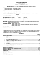
1
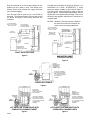
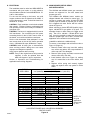
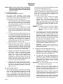
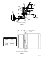
Publication Date 6/11/07
MODELS
HSG200
HSG400
GAS
BURNERS
120V/50-60 HZ
220V/50 HZ
A SCOTT FETZER COMPANY
801 GLASGOW AVE.
FORT WAYNE, IN 46803
PART NO. 62484-001B
US PATENT NO. 4,388,064
WARNING: If the information in these instructions
is not followed exactly, a fire or explosion may result
causing property damage, personal injury or death.
- Do not store or use gasoline or other flammable
vapors and liquids in the vicinity of this or any other
appliance.
- WHAT TO DO IF YOU SMELL GAS
• Do not try to light the appliance.
• Do not touch any electrical switch; do not use any
phone in your building.
• Immediately call your gas supplier from a
neighbor’s phone. Follow the gas supplier’s
instructions.
• If you cannot reach your gas supplier, call the fire
department.
MEA
MASS.
ANSI Z21.17
APPROVED
FOR USE CITY
OF NEW YORK
MEA 49-83-E
- Installation and service must be performed by a
qualified, licensed installer, service agency or the gas
supplier. WARRANTY IS VOIDED IF NOT
INSTALLED BY QUALIFIED SERVICE PERSON.
NOTICE
THESE INSTRUCTIONS SHOULD BE AFFIXED TO THE BURNER
OR ADJACENT TO THE HEATING APPLIANCE.
FOR FURTHER INSTRUCTIONS AND WARNINGS,
SEE PAGE 21 OF THIS MANUAL.
SPECIFICATIONS
[SEE PAGE #1]
SPECIFICATIONS MODELS
HSG200, HSG400
NATURAL OR PROPANE GAS
NOTE: Dimensions in ( ) are informational only. English values take priority.
HSG200
Maximum Input Capacity - 200 MBtu/HR (211000 kJ)
Minimum Input Capacity - 60 MBtu/HR (63300 kJ)
HSG400
Maximum Input Capacity - 400 MBtu/HR (422000 kJ)
Minimum Input Capacity - 200 MBtu/HR (211000 kJ)
SUPPLY LINE PRESSURE REQUIRED: Natural or Propane 5.5 W.C. (1370 Pa) Minimum, 14.0 W.C. (3487 Pa)
Maximum
AIR TUBE DIAMETER: 4 inches (101.6 mm)
AIR TUBE LENGTHS:
(See Fig. 12C for
Overall Dimensions)
HSG200
HSG400
HSG200/400
HSG200/400
6 inches
6.25 inches
9.00 inches
12.00 inches
(152.4 mm)
(158.75 mm)
(228.6 mm)
(304.8 mm)
MOUNTING: Adjustable flange standard (deduct 1 1/8 inch (28.575 mm) from above air tube lengths when using
flange). Optional pedestal mounting.
STANDARD VOLTAGE:
120 VAC / 60 HZ/ 1 Phase
120 VAC / 50 HZ/ 1 Phase (Special motor installed with max capacity reduced 20%)
220 VAC / 50 HZ/ 1 Phase
FLAME SAFETY: 24 VAC Electronic
IGNITION: 7300 VAC Direct Spark
GAS VALVE: 3/4 x 3/4 (19.05 mm x 19.05 mm) NPT 3 Function Redundant 24 VAC
*200 MBtu/HR (211000 kJ) (200,000 BTU [58.62 kW] / HR) or 400 MBtu/HR (42200 kJ) (400,000 BTU [117.24 kW]
/ HR) at sea level. Derate input for altitude over 2000 ft. (609.6 m) by 4% each 1000 ft. (304.8 m) above sea level.
(one gallon (3.79 L) fuel oil = 140 MBtu/HR (14770 kJ)).
CONTENTS
PAGE
SECTION I INSTALLATION .........................................................................................................................................1
A. GENERAL .........................................................................................................................................................2
B. VENTILATION ...................................................................................................................................................2
C. HEATING APPLIANCE INSPECTION ..............................................................................................................2
D. CHIMNEY, FLUE PIPE AND DRAFT CONTROL ..........................................................................................2-3
E. COMBUSTION CHAMBER ...............................................................................................................................4
F. GAS PIPING ......................................................................................................................................................4
G. ELECTRICAL....................................................................................................................................................5
H. MAIN BURNER ORIFICE SIZING AND INSTALLATION .................................................................................5
I. COMBUSTION GAS VALVE...............................................................................................................................6
SECTION II INITIAL START UP................................................................................................................................7-8
SECTION III OPERATION AND TROUBLESHOOTING.........................................................................................9-14
SECTION IV SERVICE ..........................................................................................................................................15-16
PARTS LISTS .............................................................................................................................................................17
EXPLODED VIEW ......................................................................................................................................................18
TECHNICAL INFORMATION......................................................................................................................................19
WARRANTY................................................................................................................................................................20
CONSUMER INSTRUCTIONS ...................................................................................................................................21
SECTION I
INSTALLATION
A. GENERAL
The Wayne HSG200 and HSG400 power gas
conversion burners are adaptable to most types of
central heating plants previously fired by power oil
burners. Typical heating plants are gravity and forced
air circulation furnaces, hot water, steam or vapor
boilers. Power burner design makes the HSG200 and
HSG400 well suited for “negative draft” fired
appliances where an oil burner is being replaced.
Installation of these power gas conversion burner
models must conform to local codes, or in their
absence, the American National Standard for the
Installation of Domestic Gas Conversion Burners,
ANSIZ21.8 - and the National Flue Gas Code,
ANSIZ223.1 or current standard year.
NOTICE: ANSI or local installation code compliance is
the sole responsibility of the qualified installer.
B. VENTILATION
The HSG conversion burner models covered by this
manual shall not be installed in an appliance located
where normal air circulation or infiltration is limited in
providing all the air necessary for proper combustion
and draft hood dilution air.
In open basements of homes of normal construction
(without basement storm windows or tight stair doors)
infiltration of combustion air is usually sufficient to
replace that drawn up the flue, so special provisions
are seldom necessary.
When the heating appliance is installed in a tightly closed
room without ventilation openings to outdoors, or other
rooms, provisions shall be made for supplying air for
combustion through special openings, one near the floor
line and the other near the ceiling. Each is to be sized
on the basis of one square inch (645.2mm2) or more of
free area each 1,000 BTU (.29kW) input per hour.
When the building is of unusually tight construction, has
kitchen and/or bathroom ventilation fans which may be
used for exhausting air to outdoors, or has a vented
fireplace, it is recommended that combustion air be
supplied to the furnace room through intakes extending
to the outside of the building and terminating in down
turned fittings, suitably arranged to prevent obstruction
from snow or rain, and including a protecting screen not
smaller than 1/4 inch (6.35mm) mesh.
C. HEATING APPLIANCE INSPECTION
Clean the appliance heat exchanger interior,
combustion chamber and flue connections. Remove
all adhering tars, scale, dirt and soot. Inspect the heat
exchanger for obvious and potential flue gas leaks.
Cement all joints around the appliance base and
access openings to prevent air and/or flue gas leakage
into or out of the combustion chamber.
Warm Air Furnaces* - Make certain the electrical
characteristics of the fan and limit switch correspond to
those required by this burner and that they are in
proper working order.
Hot Water Boilers* - Make certain water temperature
and altitude gauges, pressure relief valves are in
proper working order.
Steam Boilers* - Make certain the system is pressure
tight, and that the pressure gage and pop off safety
valve are in proper working order. Existing water sight
glass permits clear observation of boiler water level.
*Where applicable, existing temperature of pressure
limit switch or low water cut-off switch operation and
electrical characteristics shall be checked to determine
their compatibility to the gas control circuitry of this
burner.
D. CHIMNEY, FLUE PIPE AND DRAFT CONTROL
The chimney should be inspected for unsafe
conditions such as excessive soot accumulation,
deteriorated masonry, blockage or potential blockage.
NOTICE: No manually adjustable flue pipe damper is
permitted on any gas burner installation.
The chimney should be lined with a corrosion resistant
material. If the chimney is unlined, consult your local
gas utility for recommendations.
WARNING: Under no circumstances should the flue
pipe be connected to the chimney of an open fireplace.
The flue pipe should be sized to carry of the flue gases
as outlined in Figure 1.
INPUT
BTU/HR (kW/HR)
UP to -120 MBH (35.172kW)
120 MBtu/HR (35.172kW) - 180 MBH (52.758kW)
180 MBtu/HR (52.758kW) - 250 MBH (73.275kW)
250 MBtu/HR (73.275kW) - 320 MBH (93.792kW)
320 MBtu/HR (93.792kW)- 410 MBH (120.171kW)
DRAFTHOOD
FLUE PIPE SIZE
5 INCH (127mm) DIAMETER
6 INCH (152.4mm) DIAMETER
7 INCH (177.8mm) DIAMETER
8 INCH (203.2mm) DIAMETER
9 INCH (228.6mm) DIAMETER
Figure 1
Strict compliance to appropriate codes should be made
regarding flue pipe clearances from combustible materials.
PAGE 2
Pitch the horizontal run of the flue pipe upward 1/4 inch
(6.35mm) per foot (.305m) or more. Run directly to the
chimney, fasten joints securely and support horizontal
runs to prevent sagging.
If the flue pipe must be extra long, it’s size should be
increased. The horizontal length of the flue pipe should
not exceed the height of the chimney above the flue
connection.
PITCH HORIZONTAL
RUN 1/4” (6.35mm) MIN.
PER FOOT (.305M)
The draft control should be hood type per Figure 2 or, IF
APPROVED BY LOCAL AUTHORITIES, a single
barometric damper suitable for gas firing per Figure 3.
The draft control should be sized the same as the flue
pipe per Figure 1, and should be located higher than the
highest part on the appliance flue passage. Refer to the
barometric draft regulator manufacturer’s instructions for
complete detail.
NOTICE: Should the flue pass through a partition,
the draft control must be located in the
same room as the heating appliance.
DO NOT EXTEND
FLUE PIPE BEYOND
INSIDE OF CHIMNEY
PITCH HORIZONTAL
RUN 1/4” (6.35mm) MIN.
PER FOOT (.305M)
VERTICAL
DRAFT HOOD
SINGLE ACTING
BAROMETRIC
DRAFT CONTROL
HORIZONTAL
DRAFT HOOD
REDUCER
CORROSION
RESISTANT LINING
CLEANOUT
SELECT EITHER
HORIZTONAL OR
VERTICAL DRAFT HOOD
CHIMNEY
CLEANOUT
DRAFT HOOD POSITONS
Figure 2
BAROMETRIC DRAFT
CONTROL POSITION
Figure 3
TO PROTECT PROPERLY
LOCATE END OF BURNER
TUBE. POSITION TUBE 1/2”
(12.7mm) SHORT OF INSIDE
OF COMBUSTION
CHAMBER
FORCED AIR FURNACE
Figure 4
EXISTING OR
ADDED TARGET
TO BACK OF COMBUSTION CHAMBER
EXISTING
PREFABRICATED
COMBUSTION
CHAMBER LINER
TO PROTECT PROPERLY
LOCATE END OF BURNER
TUBE. POSITION TUBE 1/2”
(12.7mm) SHORT OF INSIDE
OF COMBUSTION
CHAMBER
TO PROTECT PROPERLY
LOCATE END OF BURNER
TUBE. POSITION TUBE 1/2”
(12.7mm) SHORT OF INSIDE
OF COMBUSTION
CHAMBER
HOT WATER OR STEAM BOILER WITH
COMBUSTION CHAMBER TARGET
HOT WATER OR STEAM BOILER WITH
COMBUSTION CHAMBER LINER
Figure 5
Figure 6
PAGE 3
F.
E. COMBUSTION CHAMBER
A combustion chamber is normally required to
protect non-heat transfer surfaces, and to provide a
radiant bed for rapid heat transfer to the primary
surfaces of the heat exchanger. If in good condition,
the existing combustion chamber can be used.
A full combustion chamber liner is recommended for
warm air furnaces, (see Figure 4), and a target wall
or full combustion chamber liner is recommended
for wet leg cast iron or steel boilers. (See Figures 5
and 6). If a built-up chamber is necessary, use
2300˚ F (1260˚C) minimum insulating fire-brick or
fiberfrax.
THE BURNER AIR TUBE MUST NOT BE
ALLOWED TO EXTEND INTO THE CHAMBER
PROPER; IT MUST BE SET 1/2 INCH (12.7mm)
SHORT OF THE INSIDE SURFACE.
Before permanently securing the burner to the
heating appliance with either the adjustable mounting
flange or pedestal or cementing around the air tube
in the combustion chamber opening, check that the
burner head assembly is free of foreign materials and
that the sensor and electrode probes have not been
damaged or repositioned, see Figure 13.
INPUT
BTU/HR
kW/Hr
PREFERRED
WIDTH”(mm) X LENGTH”(mm) DIAM.” (mm)
50 MBtu/HR (14.655kW)
75 MBtu/HR (219.825kW)
100 MBtu/HR (293.1kW)
150 MBtu/HR (439.65kW)
200 MBtu/HR (586.2kW)
250 MBtu/HR (732.75kW)
300 MBtu/HR (879.3kW)
350 MBtu/HR (1025.85kW)
400 MBtu/HR (1172.4kW)
7 (177.8) X 7 (177.8)
7 1/2 (190.5) X 7 1/2 (190.5)
12 (304.8) X 12 (304.8)
12 (304.8) X 15 (381)
13 (330.2) X 17 (431.8)
13 (330.2) X 18 (457.2)
13 (330.2) X 20 (508)
14 (355.6) X 21 (533.4)
15 (381) X 22 (558.8)
8 (203.2)
9 (228.6)
13 (330.2)
14 (355.6)
15 (381)
16 (406.4)
18 (457.2)
20 (508)
21 (533.4)
RECOMMENDED COMBUSTION
CHAMBER SIZES
Figure 7
MANUAL SHUTOFF VALVE
GAS PIPING
NOTICE: All piping must comply with state and/or
local codes. The available gas supply pressure
should be within minimum and maximum pressures
shown in the burner specifications. If the gas supply
pressure exceeds the 14” W.C. (3.5 k Pa) maximum,
an intermediate main gas regulator must be installed
ahead of the main gas manual shut off valve shown
in Figure 8.
WARNING: Failure to install the intermediate gas
regulator will result in gas leakage from burner gas
valve.
A drip leg or sediment trap must be installed in the
supply line to the burner. See Figure 8.
A pipe union shall be installed in the gas line
adjacent to, and upstream from, the main gas
manual shutoff valve. See Figure 8.
The gas supply piping to the burner should branch
off from the main gas supply line as close to the gas
meter as possible. Do not connect to the bottom of
a horizontal section. See Figure 9 for gas supply
pipe sizes.
Use new black iron pipe and malleable fittings free
of burrs and defects. Use pipe joint compound
resistant to liquefied petroleum gases.
A 1/8” (3.175mm) NPT plugged tapping accessible
for test gauge connection shall be provided
immediately upstream of the gas supply connection
for determining gas supply pressure to the burner.
Test new supply piping for leaks. CAUTION:
DURING PRESSURE TEST FOR LEAKS IN GAS
SUPPLY PIPING, THE BURNER MUST BE
DISCONNECTED TO PREVENT EXPOSING THE
COMBINATION GAS VALVE TO PRESSURES
OVER 1/2” (3447 PaG) PSIG.
POSSIBLY
DAMAGING THE VALVE AND VOIDING THE
BURNER WARRANTY.
PIPE
SIZE
TYPE
OF GAS
3/4
(19.05mm)
1
(25.4mm)
Propane
15 (381mm) 30 (762mm) 45 (1143mm) 90 (2286mm)
Natural
Propane
DIRECTION
OF FLOW
1/8” (3.175mm) N.P.T.
PLUGGED TAPPING
PRESSURE GAGE PORT
1 1/4
(31.75mm)
Natural
Propane
TEE
UNION
1 1/2
(38.1mm)
3” MIN.
(76.2mm)
CONTROL MANIFOLD
PIPE CAP
DRIP LEG
SUPPLY LINE CONNECTION
TO BURNER
Figure 8
CAPACITY - MBtu/HR (kJ)
LENGTH OF PIPE
Natural
400
250
200
(422000kJ) (263750kJ) (211000kJ)
400
250
200
(422000kJ) (263750kJ) (211000kJ)
400
350
250
(422000kJ) (369250kJ) (263750kJ)
400
400
300
(422000kJ) (422000kJ) (316500kJ)
400
400
(422000kJ) (422000kJ)
400
(422000kJ)
CAPACITIES SHOWN ARE FOR A TOTAL PRESSURE
DROP OF 0.3” W.C. (74.73Pa) FOR 0.5” W.C. (124.55Pa)
PRESSURE DROP, MULTIPLY CAPACITY SHOWN BY 1.3.
FOR HIGHER PERMISSIBLE PRESSURE DROPS,
CONSULT YOUR UTILITY.
SUPPLY PIPE CAPACITIES IN MBtu/HR (kW)
Figure 9
PAGE 4
G. ELECTRICAL
H. MAIN BURNER ORIFICE SIZING
AND INSTALLATION
The installation must be wired and GROUNDED in
accordance with local codes or in their absence,
with the National Electric Code ANSI/NFPA No. 701987 or latest edition.
For the 120 VAC wiring to the burner, use solid
copper conductor wire not lighter than #14 AWG. If
a fused disconnect is used, it should be fused for a
minimum of 15 amps.
CAUTION: Each installation must include suitable
limit controls. Existing oil burner combination limit
and operating controls are normally not suitable for
gas burner use.
CAUTION: The burner is equipped with it’s own 24
VAC transformer. Do not add any 24 VAC power
consuming device in the 24 VAC control circuit of
the burner, as it could overload the transformer.
Set the room thermostat “heat anticipator” for the
total current draw of the 24 VAC burner operation
circuit. (HSG200 0.55 amps, HSG400 0.7 amps)
CAUTION: Label all wires prior to disconnection
when servicing controls. Wiring errors can cause
improper and dangerous operation.
Verify proper operation after servicing.
NOTE: If any of the original burner wiring must be
replaced, it must be replaced with #18
AWG 105 degrees C wire or equivalent.
Section 3- Operation and Troubleshooting for
applicable burner wiring diagrams.
ORIFICE
SIZE & DRILL
2.0” (498.2Pa)
The HSG200 and HSG400 power gas conversion
burners are approved for use with natural and
propane gas only.
The HSG200 and HSG400 burner models are
shipped labeled and orificed for natural gas. To
convert to propane gas and/or increase BTU/HR
(kcal/Hr) input on natural or propane gas, an orifice
kit is supplied with each burner with the orifices
shown in Figure 10.
When selecting a desired BTU/HR (kcal/Hr) input,
figure 140,000 BTU’s per gallon of oil input. For
example: furnace or boiler rating of 0.75gph at 100
psig. The 0.75 x 140,000 = 105,000 BTU’s input
rate. It may be possible to reduce the firing rate on
natural or propane gas 15% to 20%, as most older
appliances are oversized for the heating load.
(2.83875L x 9356 kcal = 26559.35 kcal)
To remove or interchange main orifice discs refer to
Figure 15 (Page 16).
1. Remove slotted orifice cap, Item #40, making
sure orifice cap gasket, #39, stays attached to
orifice cap and is not damaged.
2. Remove orifice spring, Item #38, to access and
remove orifice disc, Item #42.
3. Install desired orifice from Figure 10, making
sure it is seated flat in the orifice holder, Item
#37.
4. Replace orifice spring and securely tighten
orifice cap against orifice cap gasket in orifice
holder.
MANIFOLD PRESSURE
3.0” (747.3Pa)
4.0” (996.4Pa)
HSG200 NATURAL GAS
#29 - .136 (3.4544mm)
#8 - .199 (5.0546mm)
J - .277 (7.0358mm)
Q - .332 (8.4328mm)
50,000 BTU (52750kJ)
74,000 BTU (78070kJ)
112,000 BTU (118160kJ)
160,000 BTU (168800kJ)
64,000 BTU (67520kJ)
95,000 BTU (100225kJ)
138,000 BTU (145590kJ)
206,000 BTU (217330kJ)
76,500 BTU (80707.5kJ)
116,000 BTU (122380kJ)
164,000 BTU (173020kJ)
#30 - .128 (3.2512mm)
#27 - .144 (3.6576mm)
#15 - .180 (4.572mm)
D - .246 (6.2484mm)
49,000 BTU (51695kJ)
58,500 BTU (61717.5kJ)
68,200 BTU (71951kJ)
66,000 BTU (69630kJ)
78,000 BTU (82290kJ)
92,000 BTU (97060kJ)
82,000 BTU (86510kJ) 112,500 BTU (118687.5kJ) 136,000 BTU (143480kJ)
131,000 BTU (138205kJ) 187,500 BTU (197812.5kJ) 243,000 BTU (256365kJ)
HSG200 L.P. GAS
HSG400 NATURAL GAS
T - .358 (9.0932mm)
200,000 BTU (211000kJ)
15/32 - .468 (11.8872mm) 265,000 BTU (279575kJ)
248,000 BTU (261640kJ)
343,000 BTU (361865kJ)
285000 BTU (300675kJ)
400,000 BTU (422000kJ)
HSG400 L.P. GAS
K - .281 (7.1374mm)
Q - .332 (8.4328mm)
PAGE 5
190,000 BTU (200450kJ) 242,500 BTU (255837.5kJ) 295,000 BTU (311225kJ)
242,500 BTU (255837kJ) 332,500 BTU (350787.5kJ) 400,000 BTU (422000kJ)
HSG SERIES POWER GAS CONVERSION BURNERS
ORIFICE CHART
Figure 10
NOTE: For
50 cycle
application
derate input
by 15%
I.
COMBINATION GAS VALVE
The 24 VAC combination gas valve serves three (3)
functions: (1) manual gas shut-off, (2) main gas
flame pressure regulator, (3) automatic electric
redundant (double seated) gas shut off. (See
Figure 11)
The correct operating manifold orifice pressure range
for both natural and propane gas is 2.0” W.C.
(498.2Pa) minimum to 4.0” W.C. (996.4Pa)
maximum. By adjusting the pressure regulator
between 2.0” W.C. (498.2Pa) and 4.0” W.C.
(996.4Pa) on either natural or propane gas, a wide
input range can be achieved with a single orifice size.
If the desired input rating cannot be obtained within
the above manifold orifice pressure adjustment
range, the next size larger or smaller orifice should be
used. (Refer to orifice chart Fig. 10.)
approximately 2.0” W.C. (498.2Pa) to 4.0” W.C.
(996.4Pa) is factory set at 3.5” W.C (871.85Pa).
When pressure adjustment is required for setting
input capacity with a selected orifice from Figure 10,
remove the regulator cap for access to the slotted
adjustment screw. Turning the screw counter
clockwise reduces manifold orifice pressure,
clockwise increases the pressure.
NOTE: MANIFOLD PRESSURE ADJUSTMENTS
CAN ONLY BE MADE WITH THE
BURNER RUNNING AND THE GAS ON.
The 1/8” (3.175mm) NPT pressure tap for orifice
manifold pressure measurement is located on the
outlet side of the combination gas valve. Use a “u”
tube manometer or dial type pressure gauge,
scaled from “0” zero to 15.0” W.C. (3736.5Pa) to
read pressure (See Figure 11).
J. PRESSURE REGULATOR ADJUSTMENT
The combination gas valve pressure regulator,
which has an outlet pressure setting range of
1/8” (3.175mm) NPT
PRESSURE TAP
PLUG
1/8” (3.175mm) NPT
PRESSURE TAP PLUG
HSG 200/400 GAS VALVE
HONEYWELL VR8305
Figure 11
PAGE 6
SECTION II
INITIAL START UP
1. NOTE: Read the applicable sequence of
burner/primary gas control operation in
Section 3 Operation and Troubleshooting
before proceeding.
the primary air damper open or closed to visually
obtain a blue flame with well defined orange or
yellow tips for natural gas, or well defined yellow tips
for propane gas.
2. Depress the combination gas valve manual control
knob and turn to “OFF” position.
12. After the burner has been in operation for at least 10
minutes, assuring combustion chamber and heat
exchanger are fully warmed, take combustion
analysis flue gas samples just ahead of the draft
control in the flue pipe.
3. Adjust the primary air and off-cycle damper to the
start up settings shown in Figure 12A and 12B.
4. On new gas line installations, air may be trapped in
the line, the burner may experience several
lockouts until all the air is purged from the lines.
5. Turn on the main electrical power and set the
thermostat or operation control to call for heat.
Allow the burner to run a MINIMUM of 5 minutes to
purge combustion chamber and appliance heat
exchanger.
6. Set the thermostat or operating control below room
temperature, shutting the burner “OFF” 1 minute to
RESET the primary control.
7. Depress the combination gas valve manual control
now and turn to “ON” position.
8. Set the thermostat or operating control to call for
heat. The burner will start and go through the
applicable sequence of burner/primary gas control
operation, refer to step 1.
9. Once burner is running adjust the orifice manifold
pressure regulator as described in paragraph J Pressure Regulator Adjustment.
10. A more accurate BTU (kW) input can be determined
by using the NATURAL gas service meter with the
burner only on (all other gas appliances should be
off). The hand on the gas meter dial with the lowest
cubic feet valve (fastest revolving dial), should be
clocked for one complete revolution and use the
following formula.
3600 x cubic ft. (m3)pre revolution x btu (kW) valve/cub ic ft (m3) = BTU/HR (kW/Hr)
seconds per revolution
EXAMPLE: 3600 x 1 x 1000 (.2931kW) = 300,000 BTU/HR (87.93 kW/HR)
12
11. After the desired input has been obtained, re-adjust
PAGE 7
NOTE: ALWAYS USE RELIABLE COMBUSTION
TEST
INSTRUMENTS.
BEING
PROFICIENT IN THE USE OF THESE
INSTRUMENTS AND INTERPRETING
THEIR DATA IS NECESSARY FOR SAFE,
RELIABLE AND EFFICIENT BURNER
OPERATION.
13. Perform the following combustion analysis. All
adjustments below must be made with the following
instruments: draft gauge, O2 or CO2 analyze and
CO tester.
A. Adjust the primary air damper to provide about
25% excess combustion air. Confirm this by
checking the flue gas for its FREE OXYGEN
(O2) or CARBON DIOXIDE (CO2) PERCENTAGES with a test instrument. Free oxygen
should be about 4.5%, or carbon dioxide should
be about 9.5% for natural gas, 12.1% for
propane gas.
B. CARBON MONOXIDE - Should be checked for
its presence in the flue gas. This percentage
should not exceed .04% (or 400 PPM).
C. NOTE: Check overfire draft and adjust to
NEGATIVE -.01 (2.491Pa) to -.02 (4.982Pa)
inches w/c during burner operation.
D. The flue gas temperature should be between
325˚F (162.78˚C) and 550˚F (287.78˚C)for
domestic gas conversion burners. Higher flue
gas temperatures indicate overfiring or
excessive draft through the appliance. Lower
flue gas temperatures may cause excessive
condensation and indicate underfiring. Consult
your local utility or the appliance manufacturer
for acceptable flue gas temperatures.
14. FILL OUT THE INSTALLATION COMBUSTION
DATA TAG AND AFFIX IT TO THE BURNER OR
CONVERTED APPLIANCE.
CAUTION: IF THE BURNER BTU/HR (kW/Hr)
INPUT IS CHANGED, REPEAT STEP 13
SUGGESTION: All new installations should be
reinspected for proper combustion and burner
operation after one or two weeks of normal
operation.
For subsequent normal starting and shut off
procedure, refer to the “Consumer Instructions” in
the back of this manual or the instruction plate
attached to the burner.
3/8” (9.525mm)
HSG200 SET AT NO. 1
HSG400 SET AT NO. 1 1/2
Figure 12A
Figure 12B
IMPORTANT
THESE SETTINGS ARE FOR INITIAL STARTUP ONLY, AND MUST BE
READJUSTED FOR COMBUSTION EFFICIENCY.
Figure 12C
PAGE 8
SECTION III
OPERATION AND TROUBLESHOOTING
SEQUENCE OF OPERATION - HSG SERIES POWER GAS
CONVERSION BURNER UTILIZING HONEYWELL S89F
GAS PRIMARY P/N 62759-002 W/BUILT IN 30 SECOND PREPURGE
On a call for heat, voltage (24V) is applied to motor start
relay and air switch. Once the fan motor reaches
operating rpm combustion air pressure is sensed by the
air proving switch and closes the switch contacts
energizing the S89F gas primary control.
THE S89F gas primary control has an internal 30
second prepurge timer. After the initial 30 second
prepurge, an internal 8 second safe start check of the
S89F will commence. Once this is successfully
completed, the S89F simultaneously energizes the gas
valve and ignition transformer. Gas flows and the
transformer produces an approximate 7300 volt spark
end point grounded at the burner head establishing
main burner flame.
At the start of each heat cycle, there is a trial for ignition
period of four (4) seconds duration. Normally, burner
flame will be established before the end of this period.
Once the flame is established, sparking will cease and
the flame rod will provide flame monitoring to the S89F
gas control primary for the remainder of the heat cycle.
If the flame should be extinguished during the heat
cycle, the S89F gas control primary will go into the 30
second prepurge and 8 second safe start check, then
re-energize the gas valve and ignition transformer in an
attempt to establish the main burner flame. If this does
not occur within the 4 second trial for ignition period, the
S89F gas primary control will go into lockout deenergizing the gas valve and ignition transformer.
To restart the system, the main power or thermostat
must be de-energized momentarily, then re-energized.
If at any time during the heat cycle, there is an
insufficient supply of combustion air to the burner, the
air switch will open, putting the system into lockout
closing the gas valve.
HSG POWER GAS BURNER
WITH HONEYWELL S89F GAS PRIMARY
PAGE 9
SEQUENCE OF OPERATION - HSG SERIES
POWER GAS CONVERSION BURNER UTILIZING
HONEYWELL S89E GAS PRIMARY P/N 62758-002 W/ EXTERNAL
30 SECOND PREPURGE TIMER P/N 62388-001 AND RESISTOR P/N 62530-001
On a call for heat, voltage (24V) is applied to the motor
start relay and air switch. The motor relay pulls in the
motor. After the motor reaches speed, the combustion
air blower closes the air proving switch contacts,
energizing the external 30 second prepurge timer. After
the 30 second prepurge timing, the S89E is energized.
second prepurge timer and the input terminal to the
S89E gas primary control. The function of this resistor
is to keep a load on the output terminal of the external
30 second prepurge timer, after the initial call for heat
and 30 second start prepurge and 8 second safe start
check.
The S89E gas primary control has an internal 8 second
safe start check. After the initial 30 second prepurge
provided by the external timer, the S89E gas primary
control is energized, the 8 second safe start check will
commence. Once this is accomplished, the S89E
activates the gas valve allowing gas to flow to the burner
head. Simultaneously, the S89E control energizes the
ignition transformer, producing an approximate 7300
volt spark end point grounded at the burner head,
establishing main burner flame.
This promotes simultaneous re-ignition of the main
burner flame after the S89E’s 8 second safe start check,
overriding the 30 second prepurge. This is desirable in
oven or similar applications where temperatures cannot
vary drastically.
At the start of each heat cycle, there is a trial for ignition
period of four (4) seconds duration. Normally, burner
flame will be established before the end of this period.
Once the flame is established, sparking will cease and
the flame rod will provide flame monitoring to the S89E
gas primary control for the remainder of the heat cycle.
When utilizing the S89E gas primary control with the
eternal 30 second prepurge timer, a 10K ohm resistor is
wired in parallel between the output terminal of the 30
Should the flame be extinguished during the heat cycle,
the S89E primary ignition control will go into the 8
second safe start check after which time it will reenergize the gas valve and ignition transformer in an
attempt to re-establish the main burner flame. If this
does not occur within the 4 second trial for ignition
period, the S89E gas primary control will go into lockout
de-energizing the gas valve and ignition transformer. To
restart the system, the main power or thermostat must
be de-energized momentarily, then re-energized. If at
any time during the heat cycle, there is insufficient
supply of combustion air to the burner, the air switch
contacts will open, putting the system into lockout
closing the gas valve.
HSG POWER GAS BURNER
WITH HONEYWELL S89E GAS PRIMARY
PAGE 10
FLAME SENSING
The Honeywell S89 series primary ignition controls
utilize the flame current rectification principal for main
burner flame sensing.
The flame rectification phenomenon occurs as follows.
The ignited gas flame causes the immediate
atmosphere around the flame to become ionized (gas
atoms become electrically charged). The ionization
causes the atmosphere around the flame to become
electrically conductive. An AC voltage output from the
control sensing circuit is routed through the flame
sensor probe. When the sensor probe and the burner
head are both in contact with a properly adjusted flame,
the burner head with its larger surface attracts more free
electrons, thus becoming negatively charged. The
sensor probe with its small surface area gives up free
electrons, thus becoming positively charged. The free
electrons from the AC voltage in the sensor probe flow
through the ionized gas flame to the grounded burner
head. As the AC current passes through the gas flame,
it is rectified into a DC current flowing back to the
grounded side of the sensing circuit. The flame in
actuality is a switch. When the flame is present, the
switch is closed allowing current to flow through the
sensing circuit of the control. When no flame is present,
the switch is open with no current flowing through the
sensing circuit of the control.
The DC current flow is measured in units called DC
microamperers. A steady DC microamp current of .8
minimum (and steady) or higher through the sensing
circuit of the primary ignition control is sufficient to keep
the burner running without a safety lockout. See Figure
13 for sensor probe and electrode dimensional settings,
Figure 14 for flame current measurement.
Figure 13
Figure 14
PAGE 11
PAGE 12
PAGE 13
PAGE 14
SECTION IV
SERVICE
Caution: Make sure the main manual, combination
valves and main power switch are turned
off before opening burner or removing any
parts for service.
the pressure switch causing the diaphragm contacts
to close thus completing the circuit.
The function of the air proving switch is to ensure
sufficient combustion air is being developed by the
blower motor and blower wheel. Should the blower
motor fail or the blower wheel malfunction, the
burner gas valve will shut off.
A. BURNER HEAD AND
ELECTRODE/SENSOR ASSEMBLY
The burner head, electrode, sensor probe,
combination valve, orifice housing and housing
cover are part of the gas train assembly which can
be removed as one unit. (See Figure 15)
1. The air proving switch should never require
maintenance. However, should nuisance
lockouts occur, the pressure switch can be
checked. This is done by disconnecting the
yellow and white leads from the Air Proving
switch and jumpering the leads together. If the
burner functions correctly, the switch needs to
be replaced.
1. Disconnect gas line from combustion gas valve
inlet, flame sensor lead wire from gas primary,
gas valve lead wires from gas valve operator
and (orange) ignition lead wire from ignition
transformer ignition lead wire.
2. Remove the two 1/4” (6.35mm) hex slotted
screws on the top front of the housing cover and
the two 5/16” (7.9375mm) hex slotted screws
on the left and right side back of the housing
cover.
WARNING: If a jumper is used to check the switch it
must be removed or an unsafe condition
can occur resulting in death or property
damage.
2. As mentioned above, the switch should never
require maintenance. However a pinched tube
will shut off the flow of pressurized air to the
diaphragm creating a failure made similar to
bad Air Proving switch. Always check to ensure
that the clear tubing is not pinched. Make sure
the spring cover is reinstalled over tube.
3. To remove gas train assembly, gently lift up rear
of housing cover pulling rearward slightly on the
drawer assembly gradually positioning the rear
of the drawer assembly upward 90 degrees
(1.57RAD). Gently extract burner head and
electrode/sensor assembly out opening in
housing taking extreme care to not dislocate or
damage electrode or sensor probe.
4. When servicing, clean burner head ports,
electrodes and sensor probe. Inspect the
sensor probe and electrode wires and porcelain
insulators carefully for hairline cracks which
might provide an electrical leak path that could
short out the ignition spark, or flame signal.
5. Examine the electrode and sensor probe for
any serious corrosion or deterioration of metal
at the tips. Check for proper dimensional
settings of the sensor probe and electrode (see
Figure 13). Adjust and/or replace these
assemblies as necessary. Make sure that the
ignition and sensor probe wires go to the
correct electrodes and the ignition wire boot is
in place over the electrode porcelain.
6. Make sure that the burner tube end is properly
positioned in the combustion chamber entry. It
must be set 1/2” (12.7mm) short of the inside
face of the combustion chamber as shown in
figures 4, 5 or 6.
B. AIR PROVING SWITCH
The air proving switch is mounted to the housing
cover with (2) #6 self tapping screws under the gas
valve. A clear plastic tube, protected by a spring
cover, is connected to the barbed fitting on the
pressure switch while the other end is connected to
a brass barbed fitting. The plastice tube allows
pressurized air from the blower housing to travel to
PAGE 15
3. Switch is mounted in the horizontal position with
terminals up from factory. Final burner mounting
should maintain horizontal switch position.
WARNING: Damage to internal components of
burner may result, if burner is mounted in other
than horizontal position.
C.
COMBUSTION AIR BLOWER AND MOTOR
1. Cleaning of the combustion air blower is
indicated if the blades show an accumulation of
dust and lint, or if the character of the flame
indicates a deficiency of combustion air.
2. The side plate, motor and blower wheel are
removed as one assembly. Disconnect the
motor wire inside the junction box beneath the
ignition transformer. Remove the four (4) 5/16”
(7.9375mm) hex slotted screws securing
sideplate to fan housing.
CAUTION: Do not remove blower wheel from motor
shaft during periodic cleaning.
3. Should removal of the blower wheel be
necessary for cleaning or replacement of it or
the motor, the blower wheel must be positioned
correctly on the motor shaft. (Figure 16)
HSG200 blower wheel p/n 21664 is positioned
2 1/16” (52.3875mm) measured from the blower
wheel inlet ring face to the side plate face.
HSG400 blower wheel p/n 21642 is positioned
2 3/16” (55.5625mm) measured from the blower
wheel inlet ring face to the side plate face.
DRAWER ASSEMBLY
Figure 15
PART NUMBER
21664
HSG200
5 1/4 O.D.
(133.35mm)
DIM “A”
2 1/16”
(52.3875mm)
21642
HSG400
5 1/2 O.D.
(139.7mm)
2 3/16”
(55.5625mm)
MOTOR/BLOWER ASSEMBLY
Figure 16
PAGE 16
PARTS LIST - MODEL HSG 200/400 SEE FIG. 15 & FIG. 17
Item
Part No.
Description
1.
2.
100934-001
62576-003
63270-004
62576-015
63270-015
62576-027
63270-027
63270-028
62393-001
21724-011
100428-002
21664
21642
21658
20627
20627-004
100373-002
62408-001
62388-001
62530-001
60186-004
63005-002
100450-001
62406-002
62759-002
62758-002
Burner Housing
Air Tube - HSG200 6" (152.4mm)
Air Tube - HSG400 6 1/4" (158.75 mm)
Air Tube - HSG200 9" (228.6mm)
Air Tube - HSG400 9" (228.6mm)
Air Tube - HSG200 12" (304.8mm)
Air Tube - HSG400 12" (304.8mm)
Air Tube - HSG400 15" (381 mm)
Air Cone - (HSG200 only)
Adjustable Flange Assembly (includes gasket)(not shown)
Flange Gasket (not shown)
Blower Wheel HSG200 5 1/4" OD (133.35mm)
Blower Wheel HSG400 5 1/2" OD (139.7mm)
Side Plate (Used with 20627 and 20627-004 Motors Only)
Motor, Split Phase 1/7 (.107kW) or 1/8 (.093kW) HP 3450 RPM 115V/60
Motor, Split Phase 1/7 (.107kW) HP 2850 RPM 230V/50Hz (220V/50Hz)
Combustion Air Inlet Damper
Control Box (S89E & S89F)
Used with Primary safety Control
30 Sec. Prepurge Time
P/N 62758-002
Resistor Wire Assy.
(Special limit applications only)
24 Volt Transformer 120V
24 Volt Transformer 220V
Bushing
Motor Relay
Primary Safety Control H'Well S89F w/30 Sec Prepurge (220V/50Hz)
Primary Safety Control H'Well S89E w/o 30 Sec Prepurge
(Special Limit Applications Only)
Damper Indicator Pointer
Damper Decal
Pressure Switch
Pressure Switch Conversion Kit
Pressure Switch (220V/50Hz)
Thermostat Terminal Strip
Adjustment Arm Off-Cycle Damper
100371-KIT Off-Cycle Damper Kit
Junction Box (under Ignition Transformer)
Lighting Plate
Ignition Transformer 7500V
Ignition Transformer 220V/50Hz Danfoss
Electrode Assembly
Sensor Probe Assembly
Insulator Bushing (not shown)
Chamber/Manifold - HSG200 6" (152.4mm)
Chamber/Manifold - HSG400 6 1/4" (158.75 mm)
Chamber/Manifold - HSG200 9" (228.6mm)
Chamber/Manifold - HSG400 9" (228.6mm)
Chamber/Manifold - HSG200 12" (304.8mm)
Chamber/Manifold - HSG400 12" (304.8mm)
Chamber/Manifold - HSG400 15" (381 mm)
Clip, Electrode Bracket
Ignitor Support Parts Kit
11" (279.4mm) Sensor Wire - 6" (152.4mm), 6 1/4" (158.75mm) Burner
14" (355,6mm), Sensor Wire - 9" (228.6mm), 12" (304.8mm) Burner
17" (431,8mm), Sensor Wire - 15" (228.6mm) Burner
Sense Wire – 330mm Cable (220V/50Hz)
8" (203.2mm) Ignition Wire - 6" (152.4mm), 6 1/4" (158.75mm) Burner
14" (355.6mm) Ignition Wire - 9" (228.6mm), 12" (304.8mm) Burner,
15” (228.6mm) Burner
Ignition Wire – 500mm Cable (220V/50Hz)
Top Plate/Housing Cover
Strain Relief Bushing/Ignition Wire
Orifice Housing
Orifice Spring
Orifice Gasket
Orifice Cap
Gas Valve Honeywell VR8305M 4801
Orifice Package - HSG200 (not shown)
Orifice Package - HSG400 (not shown)
Optional Pedestal Mounting (not shown)
3.
4.
5.
6.
7.
8.
9.
10.
11.
12.
13.
14.
15.
16.
17.
18.
19.
22.
23.
24.
25.
26.
27.
28.
29.
30.
31.
32.
33.
34.
35.
36.
37.
38.
39.
40.
41.
PAGE 17
100377-002
100429
63263-005
63272-005
63935-001
60178-002
100372
20-21.
21319
61843
62407-001
64051-001
62391-002
62390-002
62387-001
62575-002
62575-001
62575-014
62575-012
62575-026
62575-024
62575-031
62419-001
61951-001
62411-028
62411-030
62411-068
64096-001
62909-001
62909-003
64095-001
62404-002
62304
62402-001
62410-001
62401-001
62385-001
62374-004
62459-001
62459-002
21760-001
PAGE 18
TECHNICAL INFORMATION
“Troubleshooting Guide”
NUISANCE LOCKOUTS/FLAME SENSING PROBLEMS - HSG200 & HSG400 GAS BURNERS
Wayne’s HSG series direct spark ignition (DSI) gas
burners prove flame through the process of flame
rectification. Flame rectification is achieved by placing a
small voltage on the flame sensing probe. When the
probe is surrounded by flame, the voltage on the probe
“leaks” to ground through the flame, resulting in an
electrical current. This current is interpreted by the
ignition control as the presence of flame.
One of the most common problems with gas appliances
utilizing this type of electronic flame sensing system is
the “nuisance lockout”. Lockouts are not generally due
to the burner failing to ignite, but rather simply the failure
of the system to sense the establishment of flame.
Should this situation exist for a period of time longer
than the ignition control’s state lockout timing, the
control will shut down or go into permanent lockout. The
only way to get the burner to recycle is to break, and
then reinstate power to the burner.
burner head with approximately 1/16” (1.5875mm)
clearance from the head. The probe must not be
positioned to far away from the head as this may
result in grounding out of the probe against the
inside surface of the air tube.
•
The flamerod probe should be free of soot and
creosote. Deposits may insulate the probe, leading
it not to pass the electrical charge to the flame. The
probe can be cleaned with steel wool, emery paper
or fine sandpaper. NOTE: This is the leading cause
of nuisance lockouts in dual-fuel wood/gas fired
appliances.
•
The flamerod probe may be burned away. Check it
against dimensions on the ELECTRODE AND
FLAMEROD PROBE SETTINGS drawing.
•
The dimensional location of the flamerod probe may
be incorrect, or the probe may be bent out of shape.
Check it against dimensions on the ELECTRODE
AND FLAMEROD PROBE SETTINGS drawing and
adjust if necessary.
•
The spark electrode gap may be incorrect, resulting
in no spark or an inadequate spark that will not
ignite the gas properly. Check the electrode gap
against the ELECTRODE AND FLAMEROD
PROBE SETTINGS drawing and adjust if required.
•
The high tension lead conductor from the ignition
transformer to the tip of the spark electrode may be
broken, preventing the high voltage current from
getting to the electrode tip. Check all connections
thoroughly and/or check to continuity of the lead
wire assembly with an ohmmeter.
The following situations can lead to flame sensing
problems and can be checked without
disassembling the burner:
•
The burner is not properly grounded to “earth
ground” on the line voltage.
•
The ignition control is not properly grounded to the
burner itself. Using an ohmmeter, check the wire
attached to both parts for good contact and
continuity.
•
The burner ignition control is polarity sensitive. The
polarity of the incoming line voltage may be
reversed. Verify that black and white wires are hot
and neutral respectively, and that they are
connected to the corresponding black and white
wires on the burner.
The remaining checks and/or adjustments require
removal of the gas train:
•
•
The connections from the “SENSE” terminal of the
ignition control to the end of the flamerod may be
broken at some point. Check all quick connect
terminations and connections. Check the continuity
with an ohmmeter while flexing wires to assure no
hidden conductor breakage exists. If replaced,
wiring must be of equal, or heavier gauge and
equal, or better temperature rating.
The flamerod probe may be grounded out. Assure
that the flamerod probe is not touching the burner
head. The probe should be positioned in the center
of the clearance groove on the outer edge of the
PAGE 19
Once all of the items listed previously have been
carefully checked and corrected if necessary, reinsert
the gas train assembly into the burner. NOTE: Be
careful not to bend the air proving switch sail arm (if so
equipped) or accidentally reposition either the flamerod
probe or electrode during reinstallation of the gas train
assembly.
If, after all of the above listed items have been carefully
checked, the burner still fails to work, it is due to one or
more of the following problems:
1. Unit sparks and fires but will not stay lit. Ignition
control module is malfunctioning and must be
replaced.
2. Unit does not spark. Ignition transformer is bad and
must be replaced.
LIMITED WARRANTIES FOR OIL AND
GAS BURNERS, MADE BY WAYNE AND
USED IN RESIDENTIAL INSTALLATIONS
WAYNE COMBUSTION SYSTEMS (“WAYNE”) warrants
to those who purchase its Oil Burner Models for resale or
for incorporation into a product of resale, that its burner is
free from defects in material and workmanship under
normal use and service for thirty-six (36) months from the
date of manufacture. ALL GAS BURNERS manufactured
by “WAYNE” will be similarly warranted for eighteen(18)
months from date of manufacture except where original
manufacture offers a greater warranty. (Reference #6
below) THESE LIMITED WARRANTIES DO NOT APPLY
UNLESS THE BURNER COVERED BY IT IS PROPERLY
INSTALLED BY A QUALIFIED, COMPETENT
TECHNICIAN, WHO IS LICENSED WHERE STATE
AND/OR LOCAL CODES PREVAIL, AND WHO IS
EXPERIENCED IN MAKING SUCH INSTALLATIONS, IN
ACCORDANCE WITH NFPA #31 OF THE NATIONAL
FIRE
PROTECTION
ASSOCIATION
AND
IN
ACCORDANCE WITH ALL LOCAL, STATE AND
NATIONAL CODES.
Any IN-WARRANTY burner component which is defective
in material or workmanship will be either repaired or
replaced as follows:
1. Fuel units, motors, transformers, gas valves, and
controls should be returned to an authorized service
station or distributor of WAYNE for determination of
applicability of this LIMITED WARRANTY as to either
repair or replacement, where said service station or
distributor is reasonably available in the customer’s
locality. The manufacturers of burner components
regularly publish and distribute listings showing the
locations of their network of service stations. Where
such local service is NOT available for the burner
components described above or other burner parts are
involved, these items should be returned, freight
prepaid, to WAYNE Service Department, 801 Glasgow
Ave, Fort Wayne, Indiana 46803.
2. Burners and/or component(s) determined to be
covered under this LIMITED WARRANTY by WAYNE
shall be repaired or replaced at WAYNE’s sole option.
3. WAYNE is not responsible for any labor cost for the
removal and replacement of said burner or burner
components and equipment associated therewith.
4. A burner so repaired will then carry the LIMITED
WARRANTY equal to the unexpired portion of the
original burner LIMITED WARRANTY.
If inspection by WAYNE does NOT disclose any defect
covered by this LIMITED WARRANTY, the burner or
burner component(s) will be either repaired or
replaced at the expense of the customer and WAYNE’s
regular charges will apply.
6. If the original manufacturer of a burner component
offers a warranty greater than either of our LIMITED
WARRANTIES described above, then this portion will
be added to our LIMITED WARRANTY.
This LIMITED WARRANTY does NOT cover products
which have been damaged as the result of accident,
abuse, misuse, neglect, improper installations, improper
maintenance or failure to operate in accordance with
WAYNE’s written instructions.
These LIMITED WARRANTIES do not extend to anyone
except the first purchaser at retail and only when the
burner is in the original installation site.
IMPLIED WARRANTIES OF MERCHANTABILITY AND
FITNESS FOR A PARTICULAR PURPOSE SHALL BE
LIMITED TO THE DURATION OF THE LIMITED
EXPRESS WARRANTIES CONTAINED HEREIN. WAYNE
EXPRESSLY DISCLAIMS AND EXCLUDES ANY
LIABILITY FOR CONSEQUENTIAL OR INCIDENTAL
DAMAGES OF ANY NATURE FOR BREACH OF ANY
EXPRESS OR IMPLIED WARRANTY.
5.
Some states do not allow limitation on how long an implied
warranty lasts, so the above limitation may not apply to
you. Also, some states do not allow the exclusion or
limitation of incidental or consequential damages, so the
above limitation or exclusion may not apply to you.
WAYNE neither assumes or authorizes any person to
assume for WAYNE any other liability or obligation in
connection with the sale of these products. This warranty
gives you specific legal rights, and you may also have
other rights which vary from state to state.
PAGE 20
CONSUMER INSTRUCTIONS
MAINTENANCE:
■ Keep the area around the burner clear and free of combustible materials, gasoline or other flammable liquids or
vapors. Do not obstruct burner air openings or ventilation
grilles for combustion air.
CAUTION: Check the burner flame periodically. A proper
NATURAL gas flame will appear blue at the burner face with
orange and yellow tips. A proper PROPANE gas flame will
appear blue at the burner face with yellow tips. If the flame
is too rich, it will appear billowy and yellow with hazy tips,
if too lean, it will appear short and all blue. Burner cleaning
and/or readjustment is indicated by flames that are too rich
or too lean.
WARNING: If any flame is observed when the burner is on
standby, or if the ignition spark or valve operator is heard to
come on before the motor reaches operating speed, immediately turn off the manual gas control and main power.
A dangerous condition has developed and must be corrected.
CONTACT A QUALIFIED SERVICE TECHNICIAN FOR
CLEANING, READJUSTMENT OR REPAIR.
LIGHTING INSTRUCTIONS:
See Section II Initial Start Up
1. TURN (DEPRESS) VALVE DIAL TO ON.
2. TURN MAIN POWER ON.
3. SET THERMOSTAT OR OPERATING CONTROL TO CALL
FOR HEAT.
4. WAIT 30 SECONDS. IF BURNER HAS FAILED TO LIGHT,
OR IF BURNER LIGHTS THEN GOES OUT, TURN
BURNER OFF FOR 30 SECONDS AND THEN BACK ON
FOR RESTART.
TO SHUT OFF:
1. TURN (DEPRESS) VALVE DIAL TO OFF.
2. TURN MAIN POWER OFF.
EXPLOSION HAZARD
If PROPANE gas is used and the burner is located in a
basement, crawlspace or confined space, contact your
gas supplier about installing a “gas leak” warning device.
PROPANE gas is heavier than air and can settle in low
areas or confined spaces. This would create a DANGER
OF EXPLOSION OR FIRE. If you suspect a gas leak,
follow instructions on front cover of this manual.
ELECTRIC SHOCK HAZARD
CARBON MONOXIDE
POISONING HAZARD
CARBON MONOXIDE IS A COLORLESS, ODORLESS GAS
THAT CAN KILL. FOLLOW THESE RULES TO CONTROL
CARBON MONOXIDE.
▲ Do not use this burner if in an unvented, enclosed area.
Carbon monoxide may accumulate.
HIGH VOLTAGES ARE PRESENT IN THIS EQUIPMENT
FOLLOW THESE RULES TO AVOID ELECTRICAL SHOCK.
▲ Use only a properly grounded circuit. A ground fault
interrupter is recommended
▲ Do not spray water directly on burner.
▲ Turn off power before servicing.
▲ Do not adjust the pressure regulator. High pressures
produce carbon monoxide.
▲ Read the owner’s manual before using.
▲ Check flue gases for carbon monoxide. This check
requires specialized equipment.
▲ Allow only qualified burner service persons to adjust
the burner. Special instruments and training are
required.
▲ Read the owner’s manual before using.
OVERHEATING HAZARD
SHOULD OVERHEATING OCCUR:
Shut off the manual gas control to the appliance
Do not shut off the control switch to the pump or blower.
PAGE 21
Notes
PAGE 22