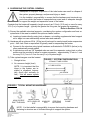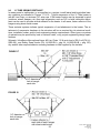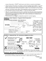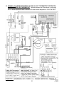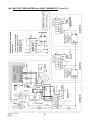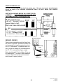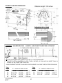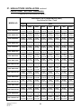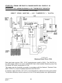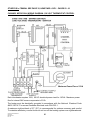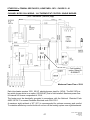
1
builderSchwank Builder S100 - S100U & Models ITB - ITBU Models LOW INTENSITY TUBE TYPE INFRARED HEATERS INSTALLATION / OWNER’S MANUAL WARNING Improper installation, adjustment, alteration, service or maintenance can cause property damage, injury or death. Read the installation and operating and maintenance instructions thoroughly before installing or servicing this equipment. SAFETY ALERT: This heater must be installed and serviced only by a trained gas service technician. Failure to comply could result in personal injury, death, fire and/or property damage. Do not store or use gasoline or other flammable vapours and liquids in the vicinity of this or any other gas fired appliance. IF YOU SMELL GAS: Extinguish any open flame Do not attempt to light this or any other appliance Don’t touch any electrical switch, or telephone Immediately call your gas supplier from a neighbor’s phone Follow any and all instruction from your gas supplier If your gas supplier is not available, call the fire department Keep this manual in a secure place . Record for future reference: Model #: Serial #: (located on heater rating label) S100-F / ITB-F I&O Manual IM101230 RD: SEP 2014 RL: 11A NOTICE: This manual is current for this product. Occasional revision of the product Certification Standard may require changes to the product and/or this manual. This publication, or parts thereof, may not be reproduced in any form, without prior written consent from The Manufacturer. Unauthorized use or distribution of this publication is strictly prohibited. Schwank Group Schwank and InfraSave brands 5285 Bradco Boulevard Mississauga, Ontario,L4W 2A6 PO Box 988, 2 Schwank Way Waynesboro, Georgia 30830 Customer & Technical Services Phone: 877-446-3727 Fax: 866-361-0523 e-mail: [email protected] www.schwankgroup.com www.infrasave.com S100-F / ITB-F I&O Manual IM101230 RD: SEP 2014 RL: 11A 2 S100 - S100U and ITB - ITBU SERIES GAS FIRED INFRARED LOW INTENSITY TUBE TYPE TABLE OF CONTENTS TOPIC TOPIC ……...PAGE 12A. MIN./MAX. SYSTEM LENGTHS ....................29 13. COMBUSTION AIR DUCT...............................30 14. GAS SUPPLY ..................................................31 HEATER EXPANSION.....................................32 FLEXIBLE GAS CONNECTION.......................33 .........PAGE INSTALLATION IMPORTANT INFORMATION - READ FIRST APPLICATION ..............................................4 HEATER EXPANSION ...........................5, 31 GAS CONNECTION ...............................5, 31 VENTING.................................................5, 26 15. ELECTRICAL AND THERMOSTAT.................34 START UP ‘SMOKE’ ....................................5 17. LIGHTING INSTRUCTIONS ...........................34 THERMOSTAT SETTING / COMFORT .......5 18. RECOMMENDED MAINTENANCE .................34 TUBE ‘GLOW’ ..............................................6 19. WIRING DIAGRAM: FENWAL DSI 24V or 120V THERMOSTAT ........................35 OR - HONEYWELL S87J DSI ........... 59 - 61 OR - CHANNEL MICRO 50N DSI ..... 62 - 65 16. HIGH ALTITUDE INSTALLATION ...................34 CLEARANCE TO COMBUSTIBLES............6 Clearances Figure & Table ........................7 STACKING HEIGHT SIGN ..........................8 19A. WIRING DIAGRAM: MULTIPLE HEATERS PER THERMOSTAT ......36 1. LABOR REQUIREMENTS ...............................9 20. FENWAL SEQUENCE OF OPERATION.........38 SPARK IGNITER SET UP ...............................39 FENWAL DSI SERVICE CHECK ...................39 2. INSTALLATION IN AIRCRAFT HANGARS .....9 3. INSTALLATION: COMMERCIAL GARAGES ........................................................9 21-A TROUBLESHOOTING GUIDE: DSI ..............40 4. INSTALLATIONS OTHER THAN 21-B TROUBLESHOOTING GUIDE: HEATER......41 SPACE HEATING.............................................9 22. START– UP / COMMISSIONING SHEET .......43 5. PRE-INSTALLATION SURVEY......................10 WARRANTY STATEMENT ...................BACK PAGE 6. MOUNTING CLEARANCES...........................11 DSI CONTROL ADDENDUM: PREVIOUS MODELS HONEYWELL S87J DSI ............................ 63 - 65 CHANNEL MICRO 50N DSI ...................... 66 - 69 SERVICE CLEARANCE.................................11 HEATER PLACEMENT GUIDELINES ...........12 PRODUCT DIMENSIONS & DATA 7. SYSTEMS WITH 90° & 180° ELBOWS .........12 23. BURNER / TUBE KIT ASSEMBLY CHART 23A. STRAIGHT TUBE SYSTEM ………….......45 23B. ‘U’ TUBE SYSTEM ………………………...46 ELBOW KIT DIMENSIONS .……… .... …..13 8. SUSPENDING THE SYSTEM........................14 9. BURNER & TUBE INSTALLATION STRAIGHT TUBE SYSTEM........................15 24. MODEL INPUTS, DIMENSIONS, WEIGHTS ..47 INSTALLATION DIMENSIONS ………. ..48 ‘U’ TUBE SYSTEM......................................17 25A. TURBULATORS - Straight Tube....................49 SPECIAL COUPLING - 100, 175 & 200 Mbh..20 25B. TURBULATORS - ’U’- Tube...........................51 9.4 SESMIC RESTRAINT ....................................22 26. Blank Page .......................................................52 26. HIGH ALTITUDE & ORIFICE CHART...... 53 - 54 9.5 HIGH WIND RESTRAINT ...............................22 27. OPTIONAL ACCESSORIES..................... 55 - 58 9.6 SEISMIC RESTRAINT ‘U’-TUBE....................23 28. BURNER PARTS LIST ............................ 59 - 61 10. REFLECTOR INSTALLATION ...................... 24 12. FLUE VENTING..............................................26 29. TUBE SYSTEM PARTS LIST...........................62 3 S100-F / ITB-F I&O Manual IM101230 RD: SEP 2014 RL: 11A WARNING Improper installation, adjustment, alteration, service or maintenance can cause property damage, injury or death. Read and understand this installation and operation manual thoroughly prior to assembly, installation, operation or service to this appliance. This heater must be installed and serviced only by a trained gas service technician. Do not store or use gasoline or other flammable vapours and liquids in the vicinity of this or any other gas fired appliance. Failure to comply could result in personal injury, death, fire and/or property damage. Do not store or use gasoline or other flammable vapours and liquids in the vicinity of this or any other gas fired appliance. This appliance may have sharp edges and corners. Wear protective clothing such as gloves and protective eye wear when servicing this or any other appliance. APPLICATION A gas-fired radiant tube heater may be installed for heating of commercial / industrial nonresidential spaces. It is beyond the scope of these instructions to consider all conditions that may be encountered. Installation must conform with all local building codes or, in the absence of local codes, with the National Fuel Gas Code, ANSI Z223.1/NFPA 54 in the U.S.A. or the Natural Gas and Propane Installation Code, CSA B149.1 in Canada. The latest edition Electrical Code ANSI/NFPA N0 70 in the U.S.A. and PART 1 CSA C22.1 in Canada must also be observed. Installation of a gas fired tube heater must conform to all heating installation design procedures including clearance to combustibles, connection to the gas and electrical supplies, and ventilation. This heater is not for installation in a Class 1 or Class 2 explosive environment, nor a residence. If installation of this equipment is in question, consult with local authorities having jurisdiction (Fire Marshall, labor department, insurance underwriter, or others). Revisions to codes and/or standards, may require revision to equipment and installation procedures. In case of discrepancy, the latest codes, standards, and installation manual will take priority over prior releases. Models S100 and ITB may be installed for heating of commercial / industrial nonresidential indoor spaces. MODELS AVAILABLE FOR OTHER APPLICATIONS: Models SPW-JZ and IWP have a powder coated water resistant burner enclosure and may be installed for heating of commercial / industrial non-residential outdoor spaces and wet indoor environments. Models STW-JZ and IW have a stainless steel water resistant burner enclosure and may be installed for heating of commercial / industrial non-residential outdoor spaces and harsh wet indoor environments. S100-F / ITB-F I&O Manual IM101230 RD: SEP 2014 RL: 11A 4 WARNING Heater Expansion It is a normal condition that during heat-up and cool-down a tube heater will expand and contract. Allowances for heater expansion must be made in the gas connection, venting and combustion air ducting. Improper installation, alteration, or adjustment can result in property damage, injury or death. Refer to Section 13 WARNING Gas Connection Improper installation, connection, or adjustment can result in property damage, toxic gases, asphyxiation, injury or death. Using an approved flexible gas connector in the USA or Type 1 hose connector in Canada, the gas supply to the heater must be connected and tested in accordance with all local, state, provincial, and national codes (ANSI Z223.1/NFPA 54 in USA; B149.1 in Canada) and as indicated in this manual. Refer to Section 13 WARNING Venting Inadequate venting of a heater may result in asphyxiation, carbon monoxide poisoning, injury or death. This heater may be directly or indirectly vented from the space. Venting must be in accordance with all local, state, provincial, and national codes (ANSI Z223.1/NFPA 54 in USA; B149.1 in Canada) and as indicated in this manual. Refer to Sections 11 & 12 WARNING Start-Up ‘SMOKE’ Condition During start up, the heating of material coatings used in the production process of tubes and reflectors will create smoke during the initial period of operation. This condition is normal and temporary . Ensure that there is sufficient ventilation to adequately clear any smoke from the space. Notify site and safety personnel to ensure that alarm systems are not unduly activated. IMPORTANT THERMOSTAT SETTING FOR COMFORT Infrared radiant (IR) heating system provide comfort with the effect of radiant heat and ambient air heat. If your IR system is controlled with a thermostat (TruTemp or ThermoControl Plus) that senses radiant heat, then set the thermostat to the desired comfort temperature (ie: 65°; 68°; 20°C). If your IR system is controlled with a standard 24V or 120V thermostat that senses only air temperature, then start with a thermostat setting that is 5° to 7°F (3° to 5°C) lower than the desired comfort temperature. Some trial and error setting may be required to ‘fine tune’ the comfort temperature that best suits your site and provides most economical operation. 5 S100-F / ITB-F I&O Manual IM101230 RD: SEP 2014 RL: 11A WARNING Tube “GLOW” It is a normal condition that the combustion tube (1st tube) can appear to “glow red”. For inputs up to 150,000 Btuh, the top surface of the tube can appear red where heat is trapped between the reflector and the tube. The stainless steel tube used for inputs 175,000 and greater can appear to entirely glow red. The tube material is designed into the heater because it can withstand the high temperature of combustion, and the “red glow” is a normal occurrence. WARNING Clearance to combustibles Location of flammable or explosive objects, liquids or vapors close to the heater may cause fire or explosion and result in property damage, injury or death. Do not use, store or locate flammable or explosive objects, liquids or vapors in proximity of the heater. The clearance to combustible material represents the minimum distance that must be maintained between the outer heater surface and a nearby surface. The stated clearance to combustibles represents a surface temperature of 90F° (50C°) above room temperature. It is the installer’s responsibility to ensure that building materials with a low heat tolerance which may degrade at lower temperatures are protected to prevent degradation. Examples of low heat tolerance materials include vinyl siding, fabrics, some plastics, filmy materials, etc. In locations used for the storage of combustible materials, signs must be posted to specify the maximum permissible stacking height to maintain the required clearances from the heater to the combustibles. Such signs must either be posted adjacent to the heater thermostats or in the absence of such thermostats in a conspicuous location. In addition to stored or stationary material, consideration must also be given to moveable objects such as cranes, vehicles, and overhead doors, and structural objects such as sprinkler heads, electrical and gas lines, and electrical fixtures. It is beyond the scope of these instructions to consider all conditions that may be encountered. Consult local authorities such as the Fire Marshall, insurance carrier, or safety authorities if you are uncertain as to the safety or applicability of the proposed installation. Refer to Figure 1 and Table 1 for the certified clearances to combustibles for the appropriate model input/size. S100-F / ITB-F I&O Manual IM101230 RD: SEP 2014 RL: 11A 6 FIGURE 1 MINIMUM CLEARANCES TO COMBUSTIBLES* - refer to Table 1 for values NOTE: A ‘PEEL & STICK’ SIGN IS SUPPLIED: USE AN INDELIBLE MARKER TO ENTER VALUES ‘H’, ‘S’, ‘F’, & ‘B’ ON . POST THE SIGN ADJACENT TO THE HEATER THERMOSTAT OR IN A PROMINENT LOCATION. See next page for details. Suspended at an angle up to 45° D Suspended horizontally A F B Maximum Stack Height H = T- C ‘T’ is measured on site, ‘C’ is in Table S S C C T T ‘T’ is measured on site, ‘C’ is in Table H H Maximum Stack Height H = T- C FLOOR FLOOR TABLE 1 MINIMUM CLEARANCES TO COMBUSTIBLES* MODEL BOTH “STRAIGHT” & “U-TUBE SUSPENDED AT AN ANGLE UP TO 45 DEGREES SUSPENDED HORIZONTALLY D B F C A S C inches (cm) inches (cm) inches (cm) inches (cm) inches (cm) inches (cm) inches (cm) S100(U)/ITB(U) 200 13 (33) 6 (15.2) 74 (188) 70 (178) 14 (36) 44 (112) 76 (193) S100(U)/ITB(U) 175 12 (31) 6 (15.2) 72 (183) 68 (172) 13 (33) 42 (107) 74 (188) S100(U)/ITB(U) 155 10 (26) 4 (10) 50 (112) 64 (163) 11 (28) 34 (87) 70 (178) S100(U)/ITB(U) 130 10 (23) 3 (8) 45 (114) 60 (152) 10 (26) 32 (81) 65 (165) S100(U)/ITB(U) 110 9 (23) 3 (8) 36 (92) 54 (137) 9 (23) 30 (76) 60 (152) 10 (26) 4 (10) 57 (145) 68 (172) 11 (28) 32 (81) 68 (172) S100(U)/ITB(U) 80 7 (18) 2 (5) 31 (79) 38 (97) 7 (18) 24 (61) 42 (107) S100(U)/ITB(U) 60 7 (18) 2 (5) 25 (64) 34 (86) 7 (18) 20 (51) 34 (86) S100(U)/ITB(U) 45 7 (18) 2 (5) 29 (74) 32 (81) 7 (18) 16 (41) 32 (81) S100 /ITB 100 *NOTE: Clearances are measured from the reflector. The clearance to combustible materials represents the minimum distance that must be maintained between the heater and a nearby surface. The stated clearance to combustibles 7 S100-F / ITB-F I&O Manual IM101230 RD: SEP 2014 RL: 11A represents a surface temperature of 90F° (50C°) above room temperature. It is the installer’s responsibility to ensure that building materials with a low heat tolerance which may degrade at lower temperatures are protected to prevent degradation. Examples of low heat tolerance materials include vinyl siding, fabrics, some plastics, filmy materials, etc. VENT END CLEARANCE: Clearances from the vent pipe are determined by local or national installation codes, but must not be less than 6 inches (15 cm). For ‘unvented’ installation, a minimum distance of 48 inches (122 cm) is required from the end of heater to a combustible surface. In locations used for the storage of combustible materials: Signs WARNING must be posted specifying the maximum permissible stacking height to maintain the required clearances from the heater to the combustibles. The signs must be posted either adjacent to the IR heating system thermostats or in the absence of such thermostats, in a conspicuous place. For your convenience a “peel and stick” sign is provided with this heater. Use a permanent marker to record the required dimensions on the sign for the pertinent heater model. To calculate the value ‘H’: (H = T - C) Measure the on site distance between bottom of the heater and the floor = ‘T’ inches (cm). Refer to Table 1 to get the value ‘C’ that corresponds to the model you are installing Subtract the clearance below the heater ‘C’ from ‘T’ to get value ‘H’. Enter this value ‘H’ on the sign. Refer to the information for the heater model being installed in Figure 1 and Table 1 to get the values for dimensions ‘S’, ‘F’ and ‘B’. Post this sign as instructed above. S100-F / ITB-F I&O Manual IM101230 RD: SEP 2014 RL: 11A 8 1. LABOR REQUIRMENTS Two persons are required to safely install this equipment. Wear gloves and other required safety protection. 2. INSTALLATION IN COMMERCIAL AIRCRAFT HANGARS Low intensity radiant tube heaters are suitable for use in aircraft hangars when installed in accordance with the latest edition of the Standard for Aircraft Hangars, ANSI/NFPA No 409 in the USA, or the Canadian Natural Gas and Propane Installation Code, B149.1. A. A minimum clearance of 10 ft (3 m) above either the highest fuel storage compartment or the highest engine enclosure of the highest aircraft which may occupy the hangar. The clearance to the bottom of the heater shall be measured from the upper surface of either the fuel storage compartment or the engine enclosure, whichever is higher from the floor. B. A minimum clearance of 8 ft (2.4 m) must be maintained from the bottom of the heater to the floor in other sections of the aircraft hangar, such as offices and shops, which communicate with areas for servicing or storage. Refer to Section 1 for proper mounting clearances to combustibles. C. Heaters must be located so as to be protected from damage by aircraft and other objects, such as cranes and movable scaffolding. D. Heaters must be located so as to be accessible for servicing and adjustment. 3. INSTALLATION IN COMMERCIAL GARAGES AND PARKING STRUCTURES Low Intensity Heaters are suitable for use in commercial garages when installed in accordance with the latest edition of the Standard for Parking Structures, ANSI/NFPA 88A, or the Standard for Repair Garages, ANSI/NFPA No. 88B, or the Canadian Natural Gas and Propane Installation Code, B149.1. WARNING An overhead heater shall be located high enough to maintain the minimum distance to combustibles, as shown on the heater rating plate, from the heater to any vehicles parked below the heater. Overhead heaters shall be installed at least 8 ft (2.4 m) above the floor. 4. INSTALLATIONS OTHER THAN SPACE HEATING Use for process or other applications that are not space heating will void the C.S.A. certification and product warranty. Process application requires field inspection and/or certification by local authorities having jurisdiction. 9 S100-F / ITB-F I&O Manual IM101230 RD: SEP 2014 RL: 11A WARNING Improper installation, adjustment, alteration, service or maintenance can cause property damage, injury or death. Read and understand this installation and operation manual thoroughly prior to assembly, installation, operation or service to this appliance. This heater must be installed and serviced only by a trained gas service technician. Do not store or use gasoline or other flammable vapours and liquids in the vicinity of this or any other gas fired appliance. Failure to comply could result in personal injury, death, fire and/or property damage. Do not store or use gasoline or other flammable vapours and liquids in the vicinity of this or any other gas fired appliance. 5. PRE INSTALLATION SURVEY It is recommended that a full heating design including heat loss calculation be conducted on the structure or area to be heated. Heater sizing and placement must consider available mounting height, sources of greatest heat loss, and the certified clearances to combustibles with respect to stored material, moveable objects (cranes, vehicles, lifts, overhead doors, etc), sprinkler system heads, and other obstructions on the site. Consideration must also be given to vent / duct placement and the allowable combined lengths of vent and duct. Carefully survey the area to be heated, and for best results place burner and combustion chamber in the coldest area(s) . Installation must conform with all local, state, provincial and national code requirements including the current latest edition ANSI Z223.1 (NFPA 54) in the U.S.A. and B149.1 installation code in Canada, for gas burning appliances and equipment. The latest edition Electrical Code ANSI/NFPA N0 70 in the U.S.A. and PART 1 CSA C22.1 in Canada must also be observed. The heating system must have gas piping of the correct diameter, length, and arrangement to function properly. For this reason, a layout drawing is necessary. S100-F / ITB-F I&O Manual IM101230 RD: SEP 2014 RL: 11A 10 6. MOUNTING CLEARANCES This heater must be mounted with at least the minimum clearances between the heater and combustibles as shown in FIG-1, TABLE 1, Page 7. It is the installer’s responsibility to ensure that building materials with a low heat tolerance which may degrade at lower temperatures are protected to prevent degradation. Examples of low heat tolerance materials include vinyl siding, fabrics, some plastics, filmy materials, etc. Positioning of lights, sprinkler heads, overhead doors, storage areas, gas and electrical lines, parked vehicles, cranes and any other possible obstruction or hazard must be evaluated prior to installation. Ensure adequate clearance around the air intake at the burner to allow sufficient combustion air supply to the heater. 6A. SERVICE CLEARANCE: The lower ‘jaw’ of the burner cabinet swings down to provide convenient service access to burner components. Provide a minimum clearance from any wall or obstruction of 6 inches (15 cm) to the access end of the burner housing, and a minimum of 24 inches (61 cm) to any ONE side to allow servicing of burner, blower and controls. (see Figure 2) - the minimum clearances to combustibles must always be maintained. For guidelines to heater placement refer to TABLE 2 (below). FIGURE 2 11 S100-F / ITB-F I&O Manual IM101230 RD: SEP 2014 RL: 11A TABLE 2: GUIDELINES FOR HEATER PLACEMENT DISTANCE – OUTSIDE WALL TO HEATER LONG AXIS (PARALLEL TO WALL) IN “FEET” MOUNTING HEIGHT ft (m) MAXIMUM DISTANCE BETWEEN HEATERS ft (m) S100 / ITB 200 18 – 25 (6 - 8) 50 (15) 17 – 25 (5 - 8) S100 / ITB 175 18 – 25 (6 - 8) 50 (15) 17 – 25 (5 - 8) S100 / ITB 155 16 – 21 (5 - 7) 45 (14) 15 – 20 (5 - 7) S100 / ITB 130 15 – 21 (5 - 7) 40 (12) 15 – 20 (5 - 7) S100 / ITB 110 13 – 19 (4 - 6) 35 (11) 13 – 18 (4 - 6) S100 / ITB 100 13 – 19 (4 - 6) 35 (11) 13 – 18 (4 - 6) S100 / ITB 80 10 – 16 (3 - 5) 30 (9) 12 – 16 (4 - 5) S100 / ITB 60 8 – 14 (2.5 - 5) 25 (8) 11 – 15 (3.4 - 5) S100 / ITB 45 8 – 12 (2.5 - 4) 20 (6) 8 – 12 (2.5 - 4) MODEL “Straight” or “U-Tube” HORIZONTAL ft (m) ANGLE COMBUSTIBLE CLEARANCE BEHIND (refer to Table 1) * RECOMMENDED MOUNTING HEIGHTS are typical to provide optimum comfort in general space heating applications. Variance to these typical heights can occur in some applications: Higher mounting heights due to structure or application requirements Lower mounting heights for area or ‘spot’ heat, or in areas with greater infiltration losses (near overhead doors, etc) IMPORTANT: Single or multiple heater placement must be such that continuous operation of heater(s) will not cause combustible material or materials in storage to reach a temperature in excess of ambient temperature plus 90F° (50C°). It is the installer’s responsibility to ensure that building materials with a low heat tolerance which may degrade at lower temperatures are protected to prevent degradation. Examples of low heat tolerance materials include vinyl siding, fabrics, some plastics, filmy materials, etc. Refer to “Clearance to Combustibles” information on pages 6 to 8, and Figure 1 and Table 1. 7. SYSTEMS INCORPORATING 90° ELBOWS AND 180° ELBOWS The radiant tube heater can be installed in configurations as illustrated in FIGURE 4. (below) with a maximum of two 90° elbows per heater. The use of elbows reduces the total maximum vent allowable. (See Section 11 : Flue venting) S100-F / ITB-F I&O Manual IM101230 RD: SEP 2014 RL: 11A 12 90° elbows (JS-0528-SM) are shipped as a kit with one coupler, and two reflector end caps. The S100 / ITB is available in a “U-Tube” model - S100U / ITBU - using a 180° turn box. A double wide reflector covers the double tube run. Alternately, for a 180° elbow, order 2 x 90° kits that connect to create a 180°. IMPORTANT: Models with input 100 Mbh x 20 ft (30 kW x 6 m) must only be installed as a straight system with no elbows allowed at the 10 ft (3 m) location. Elbow Location / Input: A minimum run of straight radiant tube must be connected to the burner before any elbow as follows: Inputs 200 (60 kW) and 175 Mbh (51 kW) = 25 ft (7.6 m); Input 150 Mbh (44 kW) = 20 ft (6 m); Inputs 125 Mbh (37 kW) and 110 Mbh (32 Kw) = 15 ft (4.6 m); and Inputs 80 Mbh (23 kW), 60 Mbh (18 kW), and 45 Mbh (13 kW) a minimum of 10 ft (3 m) straight tube before elbow. FIGURE 3 SYSTEM ELBOW KIT - see page 50 for 180° elbow dimensions FIGURE 4 90° ELBOW INSTALLATION 4 2 4 1 7 2 6 3 1 2 3 4 End-Cap Reflector End Cap Flange OVER Reflector End Cap Flange UNDER Reflector 5 3 5 900 Elbow 6 Tube Coupler 7 Unswaged end of elbow and tube (swage of previous tube or elbow inserted). 13 S100-F / ITB-F I&O Manual IM101230 RD: SEP 2014 RL: 11A 8. SUSPENDING THE SYSTEM - GENERAL Inadequate or improper suspension of the tube heater can result in collapse of the system, property damage, and personal injury or death. It is the installer’s responsibility to ensure that the hardware and structural supports from which the heater is suspended are sound and of adequate strength to support the weight and expansion forces of the heater. Consider that the heater will expand in length as much as 1/2 inch (12.5 mm) or more for every 10 ft (3 m) of system length – typically the greater the firing rate, the greater the expansion. Refer to Sections 13 & 14 1) Survey the available structural supports, considering the system configuration and heat requirements of the area to establish the optimum heater location. a) Locating a heater directly under joists or beams, or installing supplemental steel support rail or angle iron can substantially reduce labor and materials 2) Hardware with a minimum 60 lb. (30 kg) work load must be used at each heater suspension point. A #8 Jack Chain or equivalent is typically used for suspending the heater. a) Connect to the structure using typical hardware as illustrated in FIGURE 6 (below) or by other mechanically sound means b) If rigid devices such as 3/8” threaded rods are used for suspension, swing joints or other means must be provided to allow for system expansion - approximately ½ inch to 1 inch for every 10 ft (1 cm to 2.5 cm for every 3 m) of system length. 3) Tube system hangers must be located: FIGURE 5 SYSTEM CONFIGURATIONS i: Straight in line STRAIGHT TUBE SYSTEM ii: At a common height (level) NOTE: It is important that the tubes in the system are installed in alignment horizontally (level) and vertically (in line) – this will ensure system integrity ‘U’ TUBE SYSTEM 90° ELBOW FIGURE 6 TYPICAL MOUNTING HARDWARE HOOK OR EYE BOLT THROUGH BEAM CLAMP WITH HOOK OR EYE HOOK OR EYE PIPE RING OR CLEVIS BAR-JOIST CLAMP NOTE: It is the installer’s responsibility to ensure that mounting hardware and fastening to structure are of sufficient strength to support the system. S100-F / ITB-F I&O Manual IM101230 RD: SEP 2014 RL: 11A 14 9 INSTALLATION OF HANGERS, TUBES AND BURNER IMPORTANT SPECIAL NOTES: READ FIRST 1. S100/ITB 100 x 20 ft ONLY: Special Tube Connection - Refer to Section 9.3, Fig 15 2. S100/ITB 175 & 200 ONLY: Special Tube Connection - Refer to Section 9.4, Fig 16 These input rates have an unpainted titanium alloy stainless steel first tube with a flange (painted “white”), and an unpainted aluminized steel tube as the second tube; all subsequent tubes are hot rolled steel. The first tube (titanium alloy stainless steel ) will “glow red” while heater is in operation - THIS IS A NORMAL CONDITION 3. Install Flame Rectifier: 110,000, 125,000, 200,000 LP: A flame rectifier is supplied in the burner kit. Prior to installing the burner onto the flanged tube, insert the flame rectifier into the tube to seat against the tube flange. 4. IF a 90° elbow is to be installed in the system, refer NOW to Section 7 and the Elbow Kit installation instructions supplied with the kit TURBULATOR NOTES: Also refer to Table & Illustration pages 49, 50 & 51 1. 60,000, & 80,000 Btuh: 30 ft heater: REMOVE 5 ft turbulator from the 2nd tube (aluminized steel) in the system. Steel tube with 8 ft turbulator installs at vent end. 2. 200,000 x 60 ft & 70 ft: REMOVE SHORT PIECE OF TURBULATOR FROM UPSTREAM END OF LAST TUBE PRIOR TO INSTALLATION OF TUBE 3. In a Tube Kit package tubes with turbulators are labelled as to their location in the system. Also refer to the TURBULATOR Table and Illustration in Sections 25A & 25B. 15 S100-F / ITB-F I&O Manual IM101230 RD: SEP 2014 RL: 11A 9.1 S100 / ITB STRAIGHT TUBE SYSTEM ~ BURNER AND TUBE INSTALLATION For “U-Tube” Systems S100U / ITBU refer to section 9.2 page 17 ) Install Hangers: i: No closer than 3” (5 cm) and no further than 5” (10 cm) from the burner/tube flange ii: No closer than 6” (15 cm) either side of a tube connection in the system iii: No further than 24” (61 cm) either side of a tube connection in the system 2) With all hangers in alignment and suspended at the same height, insert first aluminized tube section, through 4" hole into first two wire hangers. NOTE: INSTALL THE FIRST AND SECOND TUBES (FROM BURNER END) WITH THE WELDED SEAM ALONG THE TUBE LENGTH FACING DOWNWARD. Labels on tubes identify those with turbulators and indicate their location in the system. 3) Bolt burner to flange on first tube section, SEE FIGURE 8. IMPORTANT NOTE: Models with inputs 100,000, 175,000 & 200,000 refer to section 9.3 4) Slide a Torctite tube coupler over the swaged end of the first tube, then join the second tube over the swage in the first tube 5) Slide the Torctite coupler into position across the center of the joint - SEE FIGURE 9 6) IMPORTANT: TOURQUE THE COUPLER BOLTS TO 40 ft-lbs 7) Subsequent lengths of tube can then be installed, by joining them together swaged portion inside the next tube and locking the joints using the Torctite coupler. SEE FIGURE 9. 8) If there is a 90° elbow in the system refer to Section 7 and Figures 3 & 4 FIGURE 7: STRAIGHT TUBE TYPICAL HANGER & SUPPORT SPACINGS 6” MIN. to 24” SUSPEND ALL TUBES BY TWO (2) HANGERS PER 10’ LENGTH, LOCATE HANGERS BETWEEN 6” to 24” FROM EACH TUBE CONNECTION. 1ST & 2ND TUBES FROM BURNER END: INSTALL WELDED SEAM FACING DOWNWARD. 1 - END CAP 2 - WIRE HANGER 3 - BURNER ASSEMBLY 4 - COMBUSTION AIR OPTIONS: 4A - JS-0532-SE 4” INTAKE ADAPTER S100-F / ITB-F I&O Manual IM101230 RD: SEP 2014 RL: 11A 4B - JS-0532-VC 4” WALL CAP 4C - JA-0528-XX 4” ROOF CAP 5 - SIGHT GLASS 6 - ALUMINIZED TUBE WITH FLANGE 7 - TORCTITE TUBE COUPLER 16 8 - STEEL TUBE(S) 9 - REFLECTOR 10 - FLUE VENT TERMINAL 11 - BURNER SUPPORT CHAIN 12 - HANGER SUPPORT CHAINS FIGURE 8: BOLT BURNER TO TUBE FLANGE Note: A gasket is not required between burner and tube flange 1. Fifth Nut (Holds Inner Burner to Housing - Do Not Loosen or Remove) 4 2. Install Flame Rectifier inputs 110,000, 125,000, 200,000 LP: A flame rectifier is supplied in the burner kit. 2 Prior to installing the burner onto the flanged tube, insert the flame rectifier into the tube to seat against the tube flange. 3 3. Insert four burner bolts through the tube flange, secure tightly with lock nuts. 4. Secure suspension chain to eye bolt to stabilize burner FIGURE 9: COUPLER INSTALLATION (NOTE: See Section 9.3 for ‘Special Couplers’ at first tube joint: 100,000 x 20 ft & 175 / 200,000 models) 2 4 1. Tube 2. Swaged end of upstream tube 3. Tube Coupler 4. Centre coupler over tube joint Tighten coupler bolts to 40 ft-lbs. 1 1 3 FIGURE 10: HANGER / REFLECTOR ORIENTATION HORIZONTAL TO 450 FOR ANGLE LESS THAN 45° USE CHAIN TO BOTH EYES ON HANGER 45° 45° 9.2 S100U/ITBU ‘U’-TUBE SYSTEM ~ BURNER AND TUBE INSTALLATION For “Straight-Tube” Systems S100 / ITB refer to section 9.1 page 15 IMPORTANT SPECIAL NOTES: READ FIRST 1. S100U/ITBU 175 & 200 ONLY: Special Tube Connection - Refer to Section 9.4, Fig 16 These input rates have an unpainted titanium alloy stainless steel first tube with a flange (painted “white”), and an unpainted aluminized steel tube as the second tube; all subsequent tubes are hot rolled steel. The first tube (titanium alloy stainless steel ) will “glow red” while heater is in operation - THIS IS A NORMAL CONDITION 2. TURBULATORS: Also refer to Table page 47 155 Models (150,000 Btuh): 2 ft turbulator is supplied in the Burner Kit and field installed: 155 x 20 ft U heater: Insert 2 ft turbulator in end of third tube in the system (1st 17 S100-F / ITB-F I&O Manual IM101230 RD: SEP 2014 RL: 11A tube after turn box), prior to the 10 ft turbulator that is factory installed in the last tube (total 12 ft turbulator) 155 x 30 ft U heater: Discard 2 ft turbulator - not required. All other turbulators are factory installed inside tube(s) that are clearly labeled with instruction as to where the tube(s) must be installed - Also see page 47 1) Install Hangers using chain or other suitable suspension hardware at each side of the hanger: See Figure 11 next page i: Two hangers for first section (from burner), and one hanger for each additional section ii: No closer than 12” (30 cm) and no further than 14” (35 cm) from the burner/tube flange iii: No closer than 6” (15 cm) from a tube connection in the system iv: No further than 18” (61 cm) from a tube connection in the system v: If angle mounting a ‘U’ Tube model, the vent side must be in the upper position 2) With all hangers in alignment and suspended at the same height (and angle), insert first aluminized tube section on to the first two hangers: See Figure 12A next page Also lay the vent end tube on to the first two hangers - check tubes for turbulator label to ensure the correct tube is located at the vent end NOTE: INSTALL THE FIRST AND SECOND TUBES (FROM BURNER) WITH THE WELDED SEAM ALONG THE TUBE LENGTH FACING DOWNWARD 3) Fasten flanged tube to hangers with ‘U’ bolts: All tubes on the burner-side of the heater are bolted to the hangers with ‘U’ bolts Tubes on vent-side simply rest in the hanger notch and do not fasten to the hanger. 4) Bolt burner to flange on first tube section - SEE FIGURE 8 previous page. IMPORTANT NOTE: Models with inputs 175,000 & 200,000 refer to section 9.3 5) Slide a Torctite tube coupler over the swaged end of the first tube, then join the second tube over the swage in the first tube 6) Slide the Torctite coupler into position across the center of the tube joint - SEE FIGURE 9 7) IMPORTANT: TOURQUE THE COUPLER BOLTS TO 40 ft-lbs 8) Subsequent lengths of tube can then be installed on both sides of the hangers by joining them together swaged portion inside the next tube and locking the joints using the Torctite coupler. SEE FIGURE 9. Note that 155 x 20’U requires field installation of a 2 ft turbulator (packed in Burner Kit carton) in the swaged end of the third tube in the system (1st tube after turn box on vent run side) 9) Install Turn Box: See Fig 12B The Turn Box has “long” and “short” tube legs The ‘long’ leg attaches to the burner-run tubes The ‘short’ leg attaches to the vent-run tube side - tubes end short of burner for connection of vent pipe S100-F / ITB-F I&O Manual IM101230 RD: SEP 2014 RL: 11A 18 FIGURE 11 ‘U’-TUBE TYPICAL HANGER & SUPPORT SPACING SUSPEND FIRST TUBES BY TWO (2) HANGERS, THEN SUBSEQUENT SECTIONS BY ONE HANGER LOCATE HANGERTS BETWEEN 6” to 18” FROM EACH TUBE COUPLER. INSTALL FIRST AND SECOND TUBES (FROM BURNER END) WITH WELDED SEAM FACING DOWNWARD. 1 - END CAP 2 - WIRE HANGER 3 - BURNER ASSEMBLY 4 - COMBUSTION AIR OPTIONS: 4A - JS-0532-SE 4” INTAKE ADAPTER 4B - JS-0532-VC 4” WALL CAP 4C - JA-0528-XX 4” ROOF CAP 5 - SIGHT GLASS 6 - ALUMINIZED TUBE WITH FLANGE 7 - TORCTITE TUBE COUPLER 8 - STEEL TUBE(S) 9 - REFLECTOR 10 - FLUE VENT TERMINAL 11 - BURNER SUPPORT CHAIN 12 - HANGER SUPPORT CHAINS FIGURE 12 ‘U’ TUBE MODELS ‘U’ TUBE HANGER FIGURE 12A TURN BOX FIGURE 12B FIGURE 13 ‘U’ TUBE MODEL ORIENTATION 19 S100-F / ITB-F I&O Manual IM101230 RD: SEP 2014 RL: 11A 9.3 SPECIAL COUPLING: 100,000 Btuh x 20 ft NOTE: The joint of 1ST & 2ND tubes of the 100,000 x 20 ft heater experiences strong forces of expansion. Follow instructions below for special coupling of the tubes and orientation of the turbulator in the 2nd tube.. SPECIAL COUPLER INSTALLATION 1. Install first tube so that the welded seam along the tube length is in the lower half of the tube facing downward 2. Slide the loosened tube coupler on to the first tube, past the swage 3. The second tube is supplied with a ¼” hole in the tube at the female end. 4. Slide second tube over swaged end of first tube so that ¼” hole is located 90° up from the bottom (3 or 9 o’clock position) 5. Note that the spine of the turbulator should be oriented in a vertical position 6. Through the existing ¼” hole , drill a ¼” hole through the wall of the first tube 7. Insert ¼” rivet into the hole 8. Slide coupler into position – half onto each tube – covering the rivet head 9. Tighten coupler bolts to 40 ft-lb 10. Install reflectors TOOLS REQUIRED: Electric Drill 1/4” Drill Bit (supplied) FIGURE 15 SPECIAL COUPLING: 100,000 x 20 ft - Fasten Second Tube to First Tube Step 1 Welded seam in lower half of tube, facing downward Steps 2 thru 6 Step 5 NOTE: 100,000 Btuh x 20 ft Heater TURBULATOR ORIENTATION Step 7 2 ft 1/4” Rivet Install tube with turbulator spine in vertical position for best performance with 8 ft turbu- Steps 8 &9 VIEW INSIDE TUBE: Ensure the 8 ft (2.4 m) turbulator installed in the second tube is oriented with its spine in a vertical position, and located at the vent end of the tube. This will result in the best performance and radiant output from the system. S100-F / ITB-F I&O Manual IM101230 RD: SEP 2014 RL: 11A 20 9.4 SPECIAL COUPLING: 175,000 & 200,000 Btuh NOTE: The joint of 1ST & 2ND tubes of 175,000 & 200,000 heaters experience strong forces of expansion. Follow instructions below for special coupling of the tubes. SPECIAL COUPLER INSTALLATION 1. Note the 2 holes opposite each other at the swaged end of the first tube (flanged) 2. Install the first tube with 2 holes (swaged end) at the 3 and 9 o’clock position, with the welded seam located in the lower half of tube, facing downward 3. Slide the loosened tube coupler on to the first tube, past the swage 4. The second tube has a ¼” hole at the female end. 5. Slide second tube over swaged end of first tube to align the hole in the second tube with one of the holes in the first tube 6. Final alignment of the holes can be accomplished using a screw driver or other tool 7. 8. 9. 10. IMPORTANT: Insert ¼” rivet into the hole to secure the tube connection Slide coupler into position – half onto each tube – covering the rivet head Tighten coupler bolts to 40 ft-lb Install reflectors FIGURE 16 SPECIAL COUPLING: 175,000 & 200,000 Btuh - Fasten Second Tube to First Tube - Steps 1 &2 Holes in swage of 1st tube: locate at 3 and 9 o’clock Welded seam in lower half of tube, facing downward Steps 3 to 6 1/4” Rivet Step 7 Steps 8 & 9 21 S100-F / ITB-F I&O Manual IM101230 RD: SEP 2014 RL: 11A 9.4 STRAIGHT TUBE SEISMIC RESTRAINT - LATERAL AND LONGITUDINAL In areas prone to earthquake, or as specified on a project, install lateral and longitudinal seismic restraints as indicated in Figure 15. If the heater location can be impacted by wind (outdoors, aircraft hangars, etc) refer to High Wind Restraint Section 9.5, Figure 16. These restraint systems indicate typical suspension of and attachment to the heater. Attachment of suspension hardware to the structure will be as required by site structural conditions, installation codes, and/or local engineering design requirements. Other material or systems of restraint may be specified by local or national codes, or by project engineering specifications. Schwank / InfraSave offers optional items: #2 Lion Chain 115 lb work load x 200 ft roll (PN: JL0800-XX); and Safety Snap Hooks (PN: JL-0800-SH = pkg 24; JL-0800-SH-B = pkg 100). Any and all other required seismic mounting hardware is field supplied by the installer. FIGURE 15 9.5 STRAIGHT TUBE HIGH WIND RESTRAINT - LATERAL, LONGITUDINAL, AND VERTICAL In areas with wind conditions (aircraft hangers, etc) in addition to lateral and longitudinal restraint the heater must be restrained from vertical movement. Suspend the heater using 3/8” threaded rod with 3” adjustment turnbuckle through a safety ring at each hanger location. FIGURE 16 S100-F / ITB-F I&O Manual IM101230 RD: SEP 2014 RL: 11A 22 9.6 ‘U’ TUBE SEISMIC RESTRAINT In areas prone to earthquake, or as specified on a project, install lateral and longitudinal seismic restraints as indicated in Figures 17 & 18. Typical suspension of the ‘U’-Tube heater is with #2 Lion Chain, or minimum 1/8” wire rope. If the heater location can be impacted by wind (outdoors, aircraft hangars, etc) then rigid suspension such as 3/8” rod with turnbuckle adjustment can be used to provide vertical restraint for the heater. In all cases, fasten reflector to the hangers using sheet metal screws These restraint systems indicate typical suspension of and attachment to the heater. The attachment of suspension hardware to the structure will be as required by site structural conditions, installation codes, and/or local engineering design requirements. Other types or systems of restraint may be specified by local or national codes, or by project engineering design specifications. Schwank / InfraSave offers optional items: #2 Lion Chain 115 lb work load x 200 ft roll (PN: JL0800-XX); and Safety Snap Hooks (PN: JL-0800-SH = pkg 24; JL-0800-SH-B = pkg 100). Any and all other required seismic mounting hardware is field supplied by the installer. FIGURE 17 1/4” diameter hole in hanger each side FIGURE 18 1/4” diameter hole in hanger each side 23 S100-F / ITB-F I&O Manual IM101230 RD: SEP 2014 RL: 11A 10. REFLECTOR INSTALLATION NOTE: Ensure that you are installing a single reflector - reflectors can ‘stick together’ in packaging - take care to separate them. S100 / ITB - STRAIGHT TUBE: After burner and tubes have been installed, slide the reflectors one at a time into the wire hangers. As each successive reflector is installed on an inline installation, the ends of the reflectors will overlap to provide continuous coverage over the entire tube system. The overlapping joints MUST BE FASTENED TOGETHER with a sheet metal screw. Note that for either horizontal or angle mounting of the reflector, the tube must be level along its length. Improper mounting can result in overheating of controls and combustible materials. Reflector extensions can be added to the heaters as an option. See Figure 19 and instructions next page S100-U / ITB-U - U’-TUBE: After burner and tubes have been installed, slide the doublewide reflectors one at a time onto the hangers. Fasten the FIRST hanger nearest the burner to the reflector with a sheet metal screw up through the hole in the tab at each end of the hanger. Do not fasten any other hangers in the system to reflectors. SEE FIGURE 12A As each successive reflector is installed, the ends of the reflectors will overlap to provide continuous coverage over the entire tube system. The overlapping joints MUST BE FASTENED TOGETHER with sheet metal screws - Note that for both horizontal and angle mounting, the tube must be level along its length. Improper mounting can result in overheating of controls and combustible materials. Reflector extensions can be added to the heaters as an option. See Figure 19 and instructions next page S100-F / ITB-F I&O Manual IM101230 RD: SEP 2014 RL: 11A 24 FIGURE 19 REFLECTOR EXTENSIONS (OPTIONAL - IF REQUIRED ) Reflector Extension Kit JS-0509-KT Includes: Qty 1 x 10 ft long x 10 inch deep reflector extension Qty 3 x “S” Hooks Reflector extensions may be installed one or both sides 10” 25 cm 1. Reflector extensions may be installed on one side or both sides of the reflector 2. Reflector extensions are 116” (295 cm) long 3. Holes (3) in the reflector extension for “S” hooks are located 2.25” (5.7 cm) from each end and one at the center 4. Drill 1/4” (7 mm) holes in the reflector 3/4” (2 cm) up from the bottom edge of the reflector to align with the 3 holes in the top of the reflector extension 5. Insert “S” hook down through hole in the top of the reflector extension 6. Rotate “S” hook approx. 90°, and insert into hole drilled in reflector 7. Settle reflector extension into place Insert ‘S’ hook from top and rotate 5 6 7 25 S100-F / ITB-F I&O Manual IM101230 RD: SEP 2014 RL: 11A WARNING 12. FLUE VENTING Inadequate venting of a heater may result in asphyxiation, carbon monoxide poisoning, injury or death. This heater may use a vent connection or indirect venting system to remove products of combustion from the space. Seal all vent connections with high temperature sealant. Venting must be in accordance with all local, state, provincial, and national codes (ANSI Z223.1/NFPA 54 in USA; B149.1 in Canada) and as indicated below in this manual. THIS TUBE HEATER IS APPROVED FOR VENTING DIRECTLY TO THE OUTSIDE AND UNVENTED (INDIRECT VENTING) APPLICATIONS. THE SYSTEM MUST NOT BE OPERATED WITHIN A NEGATIVE AIR CONDITION UNLESS COMBUSTION AIR IS DUCTED FROM OUTSIDE DIRECTLY TO THE BURNER. IF NEGATIVE PRESSURE IS EXPERIENCED OR ANTICIPATED, THE SECOND PORT (BARB) ON THE BLOCKED FLUE SWITCH MUST BE CONNECTED DIRECTLY TO OUTSIDE AIR USING 1/4” PLASTIC HOSE FROM BLOCKED FLUE SWITCH TO OUTSIDE OF BUILDING (FIELD SUPPLIED). UNVENTED (INDIRECT MECHANICAL VENTING SYSTEM) Indirect venting must not be used if the building experiences a negative air condition. A minimum 12 inch (30 cm) length of single walled vent pipe is to be installed on the swaged end of the last tube before any Tee, Elbow or Termination Cap is fitted. USA: Natural or mechanical means shall be provided to supply and exhaust at least 4ft3/ min/1000Btuh (0.38m3/min/kW) input of installed heaters. Some local codes may require an electrical interlock to a dedicated exhaust fan. Exhaust must be located as high as practicable in the structure above the level of the heater(s). Consult your local code and ANSI Z223.1 latest edition for all venting requirements and practices. Canada: It is required that the heater(s) be electrically interlocked to dedicated exhaust fan(s) by means of an Air Proving Switch. Exhaust fan(s) must be sized to create 300 cfm (8.5 cu m/ min) exhaust for every 100,000 Btuh (30 kW) or any fraction thereof of total input of installed equipment. Exhaust must be located as high as practicable in the structure above the level of the heater(s). Sufficient supply air must be provided. Consult the latest edition of CSA.B149.1 Section 8 for venting system and air supply requirements. VENTED TO THE OUTSIDE It is the responsibility of the installer to adhere to these instructions and all current local codes and/or ANSI Z223.1 / CSA.B149.1 latest editions for all venting requirements, and practices. It is a normal condition that during heat-up and cool-down a tube heater will expand and contract. Allowances for heater expansion must be made in the venting and combustion air ducting. Improper installation can result in property damage, injury or death. All vent pipe and adapters are supplied locally by others All venting must be minimum 26 gauge single wall vent pipe of 4” (10 cm) diameter except that portion of vent passing through a combustible wall or roof can be 4” type “B” vent as per CSA International’s interim requirement. Refer to Section 11A for vent length requirements. As an Option, two heaters may be vented through an approved common 4" x 4" x 6" Vent Tee (10 x 10 x 15 cm), supplied by the manufacturer. Vent pipe from each heater is not required to be equidistant to the vent Tee, but must comply to requirements below. A single S100-F / ITB-F I&O Manual IM101230 RD: SEP 2014 RL: 11A 26 common thermostat or “ON/OFF” switch must control the two commonly vented heaters. Install a minimum 36 inch (91 cm) length of minimum 26 gauge single walled 4” (10 cm) diameter vent pipe on the system, and a minimum 12 inch (30 cm) before any Tee or Elbow. Seal all vent connections with high temperature sealant. Vent connections must be secured with three (3) #8 sheet metal screws uniformly spaced around the circumference of the pipe. Any horizontal vent pipe must slope approx. 1/4” per foot away from heater When the vent pipe passes through a cold or unheated area where the ambient temperature is likely to produce condensation of the flue gases, the vent pipe will be insulated with a suitable material as approved and specified by the insulation manufacturer to withstand temperature up to 460°F (238°C). The vent system must always be adequately supported to prevent sagging. FIGURE 20 - Heater Expansion - Suggested Vent Configuration* * Other means of slip fit installation of the vent and duct are acceptable providing there is adequate allowance for free expansion and contraction of the system, and free flow of vent gases and combustion air. FIGURE 21 - Horizontal Vent - ALL vent pipe and adapters by others Clearances Clearances apply to JA-0528-XX 4” (10 cm) or JA-0529-XX 6” (15 cm) Vent Terminals See notes below for use of other approved vent terminations HORIZONTAL VENT THROUGH THE SIDEWALL: Any horizontal portion of the flue vent system must slope downwards approximately 1/4" per foot (63 mm/ 300 mm) toward the vent terminal - radiant tube must be level. continued …….. 27 S100-F / ITB-F I&O Manual IM101230 RD: SEP 2014 RL: 11A Use approved 4" (10 cm) (JA-0528-XX) or 6" (15 cm) (JA-0529-XX) horizontal wall vent terminal or a high-wind termination cap approved by a recognized certification agency Install termination cap a minimum of 18 inches (45 cm) from the outside wall to the inside edge of terminal opening to alleviate back pressure caused by turbulent wind conditions (See Fig. 21). This also ensures flue gases are directed away from the structure to protect building materials from degradation by the exhausted flue gases. At most two 90° elbows can be installed in a horizontal vent Installation of the vent must prevent blockage by snow and protect building materials from degradation by flue gases. A horizontal flue vent : Will not terminate less than 1 ft (30 cm) above grade level, unless its location is adjacent to public walkways, then it must not terminate less than 7 ft (2.1m) above the walkway. Below a combustible overhang or soffit: As indicated in FIGURE 21 for approved terminations: 4" (10 cm) JA-0528-XX or 6" (15 cm) JA-0529-XX For other approved terminations: Will terminate 3 ft (90 cm) or more below a combustible soffit or overhang. USA specific horizontal vent requirements: The vent terminal of a direct-vent appliance with an input between 10,000 Btu/hr (3 kW) and 50,000 Btu/hr (14.7kW) shall be installed with a 9 inch (230mm) vent termination clearance from any air opening into a building, and an appliance with an input over 50,000 Btu/hr (14.7kW) shall have at least a 12inch (300mm) vent termination clearance. The bottom of the vent terminal and the air intake shall be located at least 12inches (300mm) above grade. A horizontal vent will not terminate: Less than 3 ft (90 cm) above a mechanical air inlet located within 10 ft (3.1 m) Less than 4 ft (1.2 m) below, 4 ft (1.2 m) horizontally from, and 1 ft (0.3 m) above any window or door that opens, or gravity air inlet to a building Less than 4 ft (1.2 m) horizontal clearance from gas and electric meters, regulators and relief equipment CANADA specific horizontal vent requirements: A horizontal vent will not terminate: Within 6 ft (1.8 m) of a mechanical air supply inlet to any building. Above a gas utility meter and regulator assembly within 3 ft (0.9 m) horizontally of the vertical centerline of the regulator vent outlet to a maximum vertical distance of 15 ft (4.5 m). Within 3 ft (90 cm) of any gas pressure regulator vent outlet Within the following distances of a window or door that can be opened in any building, of any non-mechanical air-supply inlet to any building, or of the combustion air inlet of any other appliance: 12 inches (30 cm) for inputs up to and including 100,000 Btuh (30 kW) 3 ft (90 cm) for inputs exceeding 100,000 Btuh (30 kW) S100-F / ITB-F I&O Manual IM101230 RD: SEP 2014 RL: 11A 28 VERTICAL VENT THROUGH THE ROOF: FIGURE 22 It is the sole responsibility of the installer to Approved adhere to all current local codes and/or ANSI Cap Z223.1 / CSA.B149.1 latest editions for all venting requirements, and practices. Approved Use an approved ‘B-vent’ termination cap as supplied by the manufacturer of the ap- ‘B’ Vent proved ‘B-vent’ When vent and combustion air are taken through the roof, the exhaust vent should always terminate higher than the combustion air intake, to prevent recycling the products of combustion back into the heater At most three 90° elbows can be installed in a vertical vent 24” 60 cm Up 9 to 12 If roof slope exceeds 9:12 consult NFPA-54 ANSI Z223.1 or CSA-B149.1 12A. Combined System Length: Tube Heater + Vent + Combustion Air Duct: MINIMUM VENT LENGTH: (Vented or Unvented [indirect mechanical ventilation]) Minimum vent pipe length of 3 ft (91 cm) is required MAXIMUM SYSTEM LENGTH (includes: Tube Heater length + combustion air duct + vent): Each 90° elbow in the system has an equivalent length of 5 ft. A maximum of 2 elbows are allowed in any portion (duct, tube heater, vent) with the exception of up to three 90° elbows in a vertical vent run through the roof Combustion air duct may be 4” or 5” diameter and is not to exceed lengths in table below Exceeding the allowable lengths in the table below can create combustion and/or condensation problems and will void CSA Certification and the heater warranty. Do not exceed the Maximum Combined System Length regardless of the allowed maximum length of individual vent or combustion air duct INSTALLATIONS UP TO 4500 FEET (Higher altitudes refer to Section 26) Input (Btuh) Max. Vent Do Not Exceed Max. Air Duct Length Maximum Combined Length Example System Length (by Duct Diameter) Individual: 4”Ø 150,000 Btuh Heater: OR Combined: 6”Ø 4” Air Duct 5” Air Duct 4” Ø 5” Ø Tube Heater Length 50 ft 45,000 & 60,000 60 ft 80 ft 20 ft 40 ft 20 ft 80,000 70 ft 90 ft 20 ft 40 ft 20 ft 100,000 60 ft 80 ft 30 ft 50 ft 30 ft Air Duct: 4” Ø 17 ft 110,000 to 150,000 100 ft 120 ft 30 ft 50 ft 30 ft Combined Length 97 ft 175,000 & 200,000 1 x 90° elbow (vent) Straight vent 20 ft 1 x 90° elbow (duct) Max. Allowed 120 ft 140 ft 30 ft 50 ft 29 40 ft 5 ft 5 ft 100 ft Additional 20’ for 5” Ø Air Duct S100-F / ITB-F I&O Manual IM101230 RD: SEP 2014 RL: 11A 13. COMBUSTION AIR DUCTING Do not install filters on the combustion air intake. Ensure adequate clearance around the air intake to allow sufficient combustion air supply to the heater. This heater requires optional 4” Fresh Air Intake Adapter JS-0532-SE to connect a combustion air duct at the top of the burner. Standard air duct is 4” diameter, but can be increased to 5” diameter (reduce to 4” at burner) to provide up to an additional 20 feet of duct length. Vent size must remain at 4” for single vent or 6” for combined vent of two heaters - do not increase vent size. Combustion air duct must be constructed of noncombustible material. Do not use a ‘soft wall’ flexible hose for air duct, the corrugated sides of this tubing will contract and restrict air flow. A good quality industry approved hard-wall flex is allowed. When a tube heater is operated in a negative air condition or air-born dust or contaminants are present as in woodworking and welding shops, air for combustion must be ducted from outside the negative or contaminated area to the 4 inch (10 cm) diameter intake flange supplied on the blower. Maximum system, vent and duct length is listed above. Do not exceed lengths listed above for total system and individual vent or air duct Total combined system length is reduced by five feet for every 90° elbow installed in the vent or duct and in the tube system (see above for allowable total lengths) Exceeding the allowable lengths may create condensation or soot conditions and will void CSA Design Certification and product warranty The air intake will not be located less than: Three feet above grade Twelve inches from flue vent terminal of any heater with input up to 100,000 Btu/hr Three feet from flue vent terminal of any heater over 100,000 Btu/hr This heater has an optional fresh air intake duct hood for wall (JS-0532-VC) or roof cap (JS0530-XX) to bring combustion air to the heater from outside. Ensure adequate clearance around the air intake to allow sufficient combustion air supply to the heater. If drawing fresh air from outside, it is recommended that any single wall pipe containing cold air be insulated to prevent or reduce condensation on the pipe. CAUTION: In locations where chlorinated Hydrocarbons are in use, such as Trichloroethylene or Chloroethylene Nu it is essential that combustion air be brought in from a non-contaminated area. Burning the fumes from these gases will create Hydrochloric acid fumes, which are detrimental to humans, equipment and buildings. Typical sources of other contaminants are paint removers, paints, refrigerants, solvents, adhesives, degreasers, lubricants, pesticides, etc. The heater manufacturer cannot anticipate all types and chemical composition of possible contaminants at project sites. Confer with project site safety, health and engineering staff and/or local authorities having jurisdiction such as the Fire Marshall and Department of Labor for possible contaminants and any conflict with the installation of hot surface heating equipment. S100-F / ITB-F I&O Manual IM101230 RD: SEP 2014 RL: 11A 30 14. GAS SUPPLY - HEATER EXPANSION - FLEXIBLE GAS CONNECTION The gas supply must be installed to the heater using: USA: an approved Stainless Steel Flexible Gas Connector certified for use on an infrared radiant tube heater (ANSI Z21.24 CSA 6.10); CANADA: an approved Type 1 Hose Gas Connector (CAN/CGA 8.1). The heater must be isolated from the gas supply piping system by closing its individual manual shut off valve (field supplied) during any pressure testing of the gas supply piping system. CAUTION: Compensation for normal gas supply pipe expansion, and radiant tube heater expansion must be provided. All piping must conform to local codes. Provide a 1/8 in (3.2 mm) NPT plugged tapping, accessible for test gauge connection, immediately upstream of the gas supply connection to the heater. DO NOT use pressure greater than 1/2 psig to pressure check the heater. TEST FOR LEAKS: All gas piping and connections must be tested for leaks after the installation is completed. Apply soap suds solution to all connections and joints and if bubbles appear, leaks have been detected and must be corrected. DO NOT USE A MATCH OR OPEN FLAME OF ANY KIND TO TEST FOR LEAKS. NEVER OPERATE THE HEATER WITH LEAKING CONNECTIONS. The supply system should be checked first with heater turned “OFF” followed by another check with heater turned “ON”. IMPORTANT: Minimum supply line pressure at the inlet to the heater regulator must not be lower than 5.0 inches of water column pressure for natural gas. The supply gas pressure must be checked with all heaters in operation. Installation of a gas line (trap) “drip leg” is required at the inlet connection tee following the pipe drop to the heater. Failure to provide a “drip leg” could result in condensation and foreign matter passing into the gas valve. Failure to install a “drip leg” in the gas line can cause property damage, injury or death and will void the heater warranty. TABLE 4 GAS TYPE Natural Gas LINE PRESSURE INCHES WATER COLUMN MINIMUM MAXIMUM MANIFOLD PRESSURE (tap at gas valve outlet) INCHES WATER COLUMN 5.0 14.0 3.5 31 S100-F / ITB-F I&O Manual IM101230 RD: SEP 2014 RL: 11A NOTE: Access to the manifold pressure test port is on the top of the valve. A 3/16" Allen Wrench is necessary to check this. When checking or setting the manifold pressure, a water manometer should be used. Gauges which measure in ounces per square inch or pounds per square inch are not accurate enough to properly measure or set the pressure. WARNING THIS HEATER WILL EXPAND IN LENGTH AS IT HEATS UP. It is a normal condition that during heat-up and cool-down a tube heater will expand and contract. Allowances for heater expansion must be made in the gas connection, venting and combustion air ducting. Improper installation, alteration, or adjustment can result in property damage, injury or death. The Btuh input and the tube length determine the overall expansion that occurs. A typical infrared tube installation will expand toward both the Burner and the vent end. To allow heater expansion the gas supply must be installed using the flexible gas connector supplied in the burner kit: In the USA: a stainless steel Flexible Gas Connector certified for use on an infrared radiant tube heater (ANSI Z21.24 CSA 6.10); in CANADA: a Type 1 Hose Connector (CAN/CGA 8.1). Also the flue vent, and combustion air intake (if used) must be installed in such a manner that the normal expansion of the heater will be accommodated. IMPORTANT: See next page: orientation of connection between heater and gas supply. TABLE 5 Input Rating Btuh Tube Length Feet 45,000 20 1 1/4” 1/2” x 24” - JL-0771-XX 1/2” x 30” - JL-0771-RC 60,000 20 / 30 1 1/2” 1/2” x 24” - JL-0771-XX 1/2” x 30” - JL-0771-RC 80,000 20 / 30 / 40 1 3/4” 1/2” x 24” - JL-0771-XX 1/2” x 30” - JL-0771-RC 100,000 20 2” 1/2” x 24” - JL-0771-XX 1/2” x 30” - JL-0771-RC 110,000 30 / 40 / 50 2” 1/2” x 24” - JL-0771-XX 1/2” x 30” - JL-0771-RC 125,000 30 / 40 / 50 2” 1/2” x 24” - JL-0771-XX 1/2” x 30” - JL-0771-RC 150,000 40 / 50 / 60 2 1/2” 3/4” x 36” - JL-0771-YY 3/4” x 30” - JL-0771-RB 175,000 50 / 60 / 70 2 3/4” 3/4” x 36” - JL-0771-YY 3/4” x 30” - JL-0771-RB 200,000 50 2 3/4” 3/4” x 36” - JL-0771-YY 3/4” x 30” - JL-0771-RB 200,000 60 / 70 3 1/4” 3/4” x 36” - JL-0771-YY 3/4” x 30” - JL-0771-RB S100-F / ITB-F I&O Manual IM101230 RD: SEP 2014 RL: 11A Approx. USA: Mandatory Expansion Flexible Gas Connector in Length ID x Length - Part # 32 CANADA: Mandatory Type ‘1’ Gas Hose Size - Part # FIGURE 23 ORIENTATION OF FLEXIBLE GAS CONNECTOR The flexible gas connector MUST be installed in the orientation shown below as required by national installation codes and by the certification standard of this heater. This orientation protects the flexible gas connector from damage due to movement during heater expansion. It is the responsibility of the installer to ensure correct installation of the flexible gas supply. The flue vent, and combustion air duct (if installed) must also be configured in such a manner that the normal expansion of the heater will be accommodated. See Section 11. 33 S100-F / ITB-F I&O Manual IM101230 RD: SEP 2014 RL: 11A 15. ELECTRICAL AND THERMOSTAT WIRING (WIRING DIAGRAMS PAGES 35 & 36) The heater must be electrically grounded in accordance with the National Electrical Code. ANSI / NFPA 70 or current Canadian Electrical code CSA C22.1. Appliance and control wiring must be in accordance with all applicable local codes. The total load of all heaters must be considered in determining the required contact rating of the controlling thermostat or switch. Each tube heater requires 120V, 60 HZ electrical power sized for 145VA. Maximum power flow for internal 24V burner components is 21VA. The ignition control includes a 24V/120V relay switch that provides a 45 second post-purge of the system. A 24V Thermostat, TruTemp Thermostat, or 24V controller signal must be used for the post-purge feature to function. A line voltage Thermostat or an “ON/OFF” switch will disable the post-purge feature. A maximum night set-back of 9°F (5°C) is recommended for optimum economy and comfort. To maintain satisfactory comfort levels do not turn off the heating system over night/weekends. NOTICE 16. HIGH ALTITUDE INSTALLATIONS - Refer to chart in Section 26 for Restrictions When installed above the altitude stipulated below, the input must be de-rated by 4% for each 1000 ft above the altitude listed. Refer to the tables in Section 28 for orifice size and restrictions that apply to high altitude installation (including total system length restrictions). Check with your local utility regarding the gas supply and the de-rating of this appliance. Maintain gas supply pressure indicated in Table 4, page 33. USA: The factory installed orifice for this appliance is approved for altitudes zero to 2000 feet above sea level. When installed above 2000 feet, refer to Section 26. Canada: The factory installed orifice for this appliance is approved for altitudes zero to 4500 feet above sea level. When installed above 4500 feet, refer to Section 26. 17. LIGHTING INSTRUCTIONS Refer to the lighting instructions label on the outside of the burner housing. If the unit locks out on safety, main power to the unit must be manually interrupted for a 30 second reset period before the heater can be restarted. NOTE: On initial installation, the unit may lock out on safety owing to the length of time required to bleed air from the gas piping system. 18. RECOMMENDED MAINTENANCE Improper adjustment, alteration, service or maintenance can cause property damage, injury or death. This heater must be installed and serviced only by a trained gas service technician. 1. Inspect the entire heater system, venting, and gas supply connections at least annually prior to the heating season. Replace worn parts and repair deficiencies. 2. Check the inlet air opening and the blower periodically, cleaning off any lint or foreign matter. It is important that the flow of combustion and ventilation air must not be obstructed. 3. Lubricate Blower motor, by adding several drops of oil to oil ports located on the left hand side of the motor. THE TUBE HEATER BURNER IS COMPLETELY FACTORY ASSEMBLED AND TESTED. ANY ALTERATION VOIDS THE CSA CERTIFICATION AND MANUFACTURER’S WARRANTY. FOR ADDITIONAL INFORMATION, CONTACT YOUR LOCAL DISTRIBUTOR OR THE MANUFACTURER. S100-F / ITB-F I&O Manual IM101230 RD: SEP 2014 RL: 11A 34 19. FENWAL DSI: WIRING DIAGRAM: 24V OR 120 VOLT THERMOSTAT OPERATION 18. SINGLE FENWALHEATER DSI: WIRING DIAGRAM: 24V (Multiple OR 120 VOLT THERMOSTAT OPERATION PER THERMOSTAT Heaters per Thermostat—next page) SINGLE HEATER PER THERMOSTAT (Multiple Heaters per Thermostat—next page) NOTE: Models produced with FENWAL DSI have model designation: S100-F & ITB-F OTHER DSI’s: HONEYWELL S87J - PAGES 59 - 61; CHANNEL MICRO 50N - PAGES 62 - 65 35 S100-F / ITB-F I&O Manual IM101230 RD: SEP 2014 RL: 11A 19A. MULTIPLE TUBE HEATERS per 24VAC THERMOSTAT (Fenwal DSI) S100-F / ITB-F I&O Manual IM101230 RD: SEP 2014 RL: 11A 36 20. FENWAL DSI: SEQUENCE OF OPERATION / FLAME RECOVERY / SAFETY LOCKOUT Power Up / Stand By Upon applying 24 volts power to 24VAC, the control will reset, perform a self check routine, initiate full time flame sensing, flash the diagnostic LED for up to four seconds, and enter the thermostat scan state. Heat Mode When a call for heat is received from the thermostat supplying 24 volts to TH, the control checks the pressure switch for normally open contacts. The combustion blower is then energized and once the pressure switch contacts close, a 30 second purge delay begins. Following the purge period the gas valve is energized and spark commences for the 15 second trial for ignition. When flame is detected during the trial for ignition, spark is shutoff immediately and the gas valve combustion blower remains energized. The thermostat, pressure switch, and main burner flame are constantly monitored to assure the system continues to operate properly. When the thermostat is satisfied and the demand for heat ends, the main valve is de-energized immediately, the control senses the loss of flame signal and initiates a 30 second post-purge period before de-energizing the combustion blower. Failure to Light - Lockout (THREE TRIAL MODEL) This three-try control will attempt two additional ignition trials with a 30 second inter-purge between trials, before going into ‘soft’ lockout. The valve relay will be de-energized immediately, and the combustion blower will be turned off following the 30 second post purge period. If the thermostat continues to call for heat after one hour the control will automatically reset and attempt to ignite the burner again (three trials). At any time less than the 1 hour auto-reset, recovery from lockout requires a manual reset by either resetting the thermostat or removing 24 volts for a period of 5 seconds. Flame Failure - Re-Ignition If the established flame signal is lost while the burner is operating, the control will respond within 0.8 seconds. The HV spark will be energized for a trial ignition period in an attempt to relight the burner. If the burner does not light the control will de-energize the gas valve. Two more attempts will be made to relight the burner. If the burner does not relight the control will go into ‘soft’ lockout as noted above in “Failure to Light”. If flame is re-established, normal operation resumes. Combustion Airflow Problems -Lockout Combustion air flow is continually monitored during an ignition sequence by the air flow switch (PSW). If during the initial call for heat the pressure contacts are in the closed position for 30 seconds without an output to the Combustion Blower, an air flow fault will be declared and the control will remain in this mode with the combustion blower off. If the air flow switch remains open for more than 30 seconds after the combustion blower output (L1 & IND) is energized, an air flow fault will be declared and the control will stay in this mode with the combustion blower on, waiting for the air flow switch to close. When proper air flow is detected from the air flow switch input (PSW) the control begins the pre-purge period followed with a 15 second ignition sequence. If the air flow signal is lost while the burner is firing, the control will immediately de-energize the gas valve and the combustion blower will remain on. If the call for heat remains, the control will wait for proper air flow to return. If proper air flow is not detected after 30 seconds an air flow fault signal will be declared. If proper air flow is detected at any time, a normal sequence will begin with the pre-purge period. 37 S100-F / ITB-F I&O Manual IM101230 RD: SEP 2014 RL: 11A Flame Fault If at any time the main valve fails to close completely and maintains a flame, the full time flame sense circuit will detect it and energize the combustion blower. Should the main valve later close completely removing the flame signal, the combustion blower will power off following the optional post purge period. Fault Conditions The LED will flash on for 1/4 second, then off for 1/4 second during a fault condition. The pause between fault codes is 3 seconds. Error Mode Internal Control Failure Air Flow Fault Flame with No Call for heat Ignition Lockout LED Indication Steady on 1 flash 2 flashes 3 flashes MOUNTING AND WIRING The Series 35-61 is not position sensitive and can be mounted vertically or horizontally. The case may be mounted on any surface with #6 sheet metal screws. All wiring must be done in accordance with local and national electrical code. Refer to wire diagram page 35 when connecting the Series 35-61 to other components in the burner. WARNING The Series 35-61 DSI Control uses voltages of shock hazard potential. Wiring and initial operation must be done by a qualified service technician. The control must be secured in an area that will experience a minimum of vibration and remain below the operating temperature of 160ºF. All connections should be made with UL approved 105ºC rated 18 gauge, stranded, .054 thick insulated wire. Refer to wire diagram page 35 when connecting the Series 35-61 to other components in the burner. TERMINAL SPADE DESIGNATION TH PSW V1 1/4” 1/4” 1/8” IND NC L1 24 VAC V2 GND Spark 1/4” 1/4” 1/4” 1/8” 1/8” 1/4” Thermostat Input Pressure Switch Input Valve Power (MV) Inducer Blower Output Alarm (Not used) 120/240 VAC Input (Hot) 24 VAC Supply to Processor Valve (MV) Valve & System Ground Spark & Local Flame Sense CAUTION: Label all wires prior to disconnection when servicing controls. Wiring errors can cause improper and dangerous operation. A functional checkout of a replacement control is recommended. PROPER ELECTRODE LOCATION Proper location of the electrode assembly is important for optimum system performance. The electrode assembly should be located so that the spark gap is inside the flame envelope about 1 inch (2.5 cm) from the base of the flame at the burner cup. Electrodes should have a gap spacing of 3/16” (0.188” ± 0.031” or 4.76 mm ± 0.81 mm). If this spacing is not correct, the assembly must be adjusted or replaced. DO NOT adjust the curved igniter/sensor prong. Adjust/bend only the ground prong (also see next page). S100-F / ITB-F I&O Manual IM101230 RD: SEP 2014 RL: 11A 38 SPARK IGNITER SET UP Use the following diagram to check the Igniter gap. If the gap is incorrect all adjustments should be made to the GROUND PRONG/PIN ONLY! DO NOT BEND THE IGNITER PRONG!!!! USE THE BLACK BARS BELOW AS A GUIDE FOR ADJUSTMENT. USE THE BARS THAT COINCIDE WITH THE FORMAT & SIZE OF THIS PUBLICATION . IF this manual is in 8.5” x 11” “booklet” format (pages folded in half) 3/16” 1/4” then use these bars OR IF this manual is printed 8.5” x 11” “full page” format use these bars 3/16” ADJUST 1/4” Multipurpose Meter SERVICE CHECKS Use Microamp scale FC- FC+ Flame current passes through the flame from the sensor to ground. The minimum flame current necessary to keep the system from lockout is 0.7 microamps. To measure flame current, connect an analog DC microammeter to the FC- FC+ terminals per figure at right. Meter should read 0.7 µA or higher. If the meter reads below “0” on scale, meter leads are reversed. Disconnect power and reconnect meter leads for proper polarity. 39 S100-F / ITB-F I&O Manual IM101230 RD: SEP 2014 RL: 11A 21-A. TROUBLESHOOTING GUIDE - FENWAL DSI (also see Heater Troubleshooting next page) SYMPTOM RECOMMENDED ACTION(S) 1. Dead A. B. C. D. 2. Thermostat on - no blower output A. Miswired B. Bad thermostat no voltage @ terminal W C. Bad control (check LED for steady on) 3. Pressure switch input okay, but no Trial-for-Ignition after purge delay A. Miswired (check PSW terminal voltage: 24Vac ± 10%) B. Flame sense problem (existing flame: check LED - 2 flashes) C. Bad control (check line voltage between L1 & IND) 4. Valve on, no spark A. Shorted electrode B. Open HV cable C. Bad control 5. Spark on, no valve A. Valve coil open B. Open valve wire C. Bad control (check 24Vac voltage between V1 & V2) 6. Flame ok during TFI, no flame sense (after TFI) A. B. C. D. S100-F / ITB-F I&O Manual IM101230 RD: SEP 2014 RL: 11A Miswired - check electrical supply (120Vac ± 5%) Transformer bad (24Vac ± 10%) Fuse/Circuit breaker bad Bad control (check LED for steady on) Bad electrode Bad HV igniter wire Poor ground at burner Poor flame (check flame current) 40 21-B. TROUBLESHOOTING GUIDE - HEATER OPERATION WARNING Improper adjustment, alteration, service or maintenance can cause property damage, injury or death. This heater must be installed and serviced only by a trained gas service technician SEQUENCE OF EVENTS (also see DSI Troubleshooting previous page) APPLY 120 VOLTS NO REMEDY 120 VOLTS SUPPLY FAULT NO CHECK 120V TO DSI AT “L1” CHECK 120V OUT AT “IND” FROM DSI TO BLOWER SET THERMOSTAT TO CALL FOR HEAT COMBUSTION AIR BLOWER STARTS NO FAULTY RELAY SWITCH IN DSI — REPLACE DSI YES AIR PROVING SWITCH HAS CLOSED 24 VOLTS IS PRESENT AT “PSW” AT DSI CONTROL. CHECK TUBING TO SWITCH IS CONNECTED AND NOT BLOCKED OR KINKED CHECK AIR PRESSURE WITH MANOMETER CHECK FOR OBSTRUCTION IN THE AIR INTAKE REPLACE DEFECTIVE BLOWER CHECK INTEGRITY OF SWITCH REPLACE DEFECTIVE SWITCH NO YES BLOCKED FLUE SWITCH IS CLOSED 24 VOLTS IS PRESENT AT “TH” AT DSI CONTROL. CHECK TUBING TO SWITCH IS CONNECTED AND NOT BLOCKED OR KINKED CHECK AIR PRESSURE WITH MANOMETER CHECK INTEGRITY OF SWITCH REPLACE DEFECTIVE SWITCH CHECK FOR AND REMEDY ANY OBSTRUCTION IN THE VENT / TUBE NO YES SPARK IGNITER / SENSOR NO YES 24V TO GAS VALVE CONTINUED 41 CHECK DSI CONTROL FUSE FOR CONTINUITY VISIBLY CHECK IF IGNITER IS SHORTING OUT CHECK GROUND WIRING REMOVE AND INSPECT IGNITER AND LEAD CHECK BOOT OF THE IGNITION CABLE FOR SIGNS OF MELTING OR OVERHEATING IF “YES” ... TAKE PROTECTIVE ACTION TO SHIELD CABLE AND BOOT FROM EXCESSIVE TEMPERATURE; REPLACE ANY DEFECTIVE COMPONENT CHECK CERAMIC INSULATOR AND CAP CHECK SPARK GAP SETTING IS 3/16” (ADJUST BY MOVING THE GROUND PRONG ONLY) PERFORM IGNITION LEAD TEST (See SPARK IGNITION CIRCUIT INSTRUCTIONS—Section 22) GOOD SPARK.....REPLACE IGNITER NO SPARK/OR WEAK.....REPLACE CONTROL S100-F / ITB-F I&O Manual IM101230 RD: SEP 2014 RL: 11A MAIN BURNER LIGHTS NO CHECK FOR STRONG SPARK AT IGNITER........ (SEE PREVIOUS PAGE). YES CHECK FOR 24 VAC ACROSS GAS VALVE. CHECK OUTPUT VOLTAGE FROM CONTROL TERMINALS TO GAS VALVE.....IF NO VOLTAGE REPLACE CONTROL. CHECK ELECTRICAL WIRING, AND VOLTAGE BETWEEN IGNITION CONTROL AND GAS VALVE. IF OK, REPLACE GAS VALVE. SPARK STOPS WHEN BURNER LIGHTS NO CONTROL IS NOT SENSING FLAME WITHIN THE 15 SECOND TFI AND IS STILL TRYING TO LIGHT CHECK CONTINUITY OF SENSOR CABLE AND GROUND WIRE CHECK BURNER FLAME IS COVERING SENSOR. YES CHECK FLAME SIGNAL IN SERIES WITH THE GROUND AND MODULE FOR 0.7 UA MINIMUM. IF SIGNAL IS LOWER CHANGE IGNITER. IF CHECKS ARE OK.......REPLACE CONTROL. SYSTEM RUNS UNTIL CALL FOR HEAT ENDS NO NOTE: IF IGNITION CONTROLS GOES INTO A LOCKOUT, INTERRUPT POWER AND RESTART. CHECK CONTINUITY OF SENSOR CABLE AND GROUND WIRE AS A POOR GROUND COULD RESULT IN ERRATIC BEHAVIOUR AND NUISANCE SHUTDOWNS EVEN THOUGH OPERATION IS NORMAL AT THE TIME OF CHECKOUT. YES CHECK FOR EXCESSIVE HEAT AT SENSOR INSULATOR AS TEMPERATURES ABOVE 1000°F(538°C) CAUSES SHORT TO GROUND. CHECK FLAME SIGNAL IN SERIES WITH THE GROUND AND MODULE FOR A MINIMUM 1.5UA. IF SIGNAL IS LOWER CHANGE IGNITER. IF CHECKS ARE OK.....REPLACE CONTROL. CALL FOR HEAT ENDS: SYSTEM SHUTS OFF YES NO CHECK TEMPERATURE CONTROLLER. CHECK FOR FAULTY WIRING, REMOVE GAS VALVE LEAD AT CONTROL , IF VALVE CLOSES, RECHECK THE TEMPERATURE CONTROLLER AND WIRING. IF VALVE STAYS OPEN....REPLACE GAS VALVE TROUBLESHOOTING ENDS Also See DSI Info previous pages. S100-F / ITB-F I&O Manual IM101230 RD: SEP 2014 RL: 11A 42 22. START-UP / COMMISSIONING SHEET THIS EQUIPMENT HAS BEEN FACTORY FIRED AND TESTED PRIOR TO SHIPMENT. HOWEVER, THIS APPLIANCE IS NOT “PLUG & PLAY”. IT REQUIRES COMMISSIONING AND FIELD ADJUSTMENT / SPECIFICATIONS CONFIRMATION TO ENSURE SAFE AND EFFICIENT OPERATION. COMMISSIONING REPORT AS PER I&O MANUAL AND LOCAL CODES CONTRACTOR NAME: ................................................................................DATE................................ ADDRESS:............................................................................................................................................ ............................................................................................................................................................ CITY:........................................................................................ PHONE:................................................................................... CELL: ..................................................................................... JOB SITE......................................................................................................CITY................................ HEATER MODEL NUMBER:................................................................................. Located on burner rating plate HEATER SERIAL NUMBER: ................................................................................ Located on burner rating plate TO ENSURE THAT SITE CONDITIONS ARE COMPATIBLE WITH THE HEATER’S PERFORMANCE AND TO ALLEVIATE NUISANCE CALL-BACKS, THE FOLLOWING STARTUP NEEDS TO BE COMPLETED BY THE QUALIFIED GAS INSTALLER. A TECHNICIAN CALLING FOR TECHNICAL SUPPORT MUST PROVIDE THE INFORMATION FROM THE COMPLETED COMMISSIONING REPORT ON THE NEXT PAGE FAX COMPLETED REPORT TO TECHNICAL SERVICES: FAX 1-866-361-0523, VOICE 1-877-446-3727 WARNING START UP ‘SMOKE’ During start up, material coatings used in the production process of tubes and reflectors will “burn off” and create smoke during the first hour of operation. This is temporary and normal. Please ensure that there is sufficient ventilation to adequately clear the smoke from the space. Notify site and safety personnel to ensure that alarm systems are not unduly activated. 43 S100-F / ITB-F I&O Manual IM101230 RD: SEP 2014 RL: 11A QUALIFIED INSTALLER TO COMPLETE THIS TUBE HEATER COMMISSIONING REPORT TYPE OF GAS: NG LP DOES BUILDING HAVE A NEGATIVE CONDITION: YES NO IF THIS IS A HIGH ALTITUDE AREA WHAT IS THE ALTITUDE ABOVE SEA LEVEL Feet DOES APPLICATION REQUIRE FRESH AIR TO BURNER YES NO IS HEATER EXPOSED TO CHEMICAL OR CORROSIVE ATMOSPHERE: YES NO ARE ACTUAL MINIMUM CLEARANCES AS PER TABLE 3 YES NO CAN HEATER BE AFFECTED BY OVERHEAD CRANES / VIBRATION YES NO ARE GAS SUPPLY LINES ADEQUATELY SIZED FOR SYSTEM YES NO GAS LINES AND BRANCHES HAVE BEEN PURGED OF AIR: YES NO THIS HEATER FIRED WITHOUT ANY MALFUNCTION: YES NO INLET GAS SUPPLY PRESSURE WITH HEATER OPERATING : WC" GAS VALVE OUTLET (Manifold) PRESSURE WITH HEATER OPERATING: WC" WHAT IS THE LINE VOLTAGE READING AT THE HEATER VOLTS WHAT IS THE VOLTAGE READING AT THE IGNITION MODULE VOLTS WHAT IS THE FLAME SIGNAL STRENGTH IN uA FROM SENSOR: uA (microamps) IS HEATER CONTROLLED BY A THERMOSTAT YES NO IS THE THERMOSTAT STRATEGICALY LOCATED YES NO WHAT IS TOTAL LENGTH OF INSTALLED THERMOSTAT WIRE FEET WHAT IS THE GAUGE OF THE THERMOSTAT WIRE WHAT IS THE HEATER TUBE LENGTH Ft GAUGE (10ft per Tube section) FEET WHAT IS THE TOTAL LENGTH OF THE VENT (add 10ft for each bend) FEET WHAT LENGTH IS COMBUSTION AIR INTAKE (add 10ft for each bend) FEET IF REQUIRED....WHAT IS THE LENGTH OF THE TURBULATOR(S) FEET IF INSTALLED....IS TURBULATOR AT FLUE END OF SYSTEM YES NO “MAXIMUM STACKING HEIGHT” SIGN(S) - POSTED AT THERMOSTAT(S) THIS HEATER MUST BE ELECTRICALLY GOUNDED FAX COMPLETED REPORT TO TECHNICAL SERVICES: FAX 1-866-361-0523, VOICE 1-877-446-3727 S100-F / ITB-F I&O Manual IM101230 RD: SEP 2014 RL: 11A 44 23A. BURNER & TUBE KIT ASSEMBLY CHART MODELS S100 / ITB MODELS S100 & ITB are approved for indoor commercial / industrial non-residential applications. For outdoor, wet and harsh environment applications refer to models SPW-JZ / IWP (powder coated burner box) and/or STW-JZ / IW (stainless steel burner box). BEFORE INSTALLING: ENSURE you have the CORRECT TUBE KIT(s) for the BURNER INPUT S100 / ITB - TUBE KIT PART # & QUANTITY REQUIRED Tube Kit Gross Weight (lbs) Tube Length (ft) 60,000 80,000 100,000 110,000 130,000 155,000 175,000 200,000 120 10' 20' Stand-Alone Kits 120 170 20' 30' 210 Primary Kits 165 165 40' 30' 30' + Secondary Kits 120 165 20' 30' TM-4510- TM-1020- TM-1420- TM-1430- TM-1040- TM-F030- TM-1030- TM-0020- TM-0030SX SX SX SX SX SX SX SX SX INPUT (Btuh) 45,000 80 10' 20' 20' 30' 20' 30' 40' 20' 1 1 1 1 1 1 1 1 30' 40' 50' 30' 40' 50' 40' 50' 60' 50' 60' 70' 50' 60' 70' 1 1 1+ 1 1+ 1 1+ 1 1 1 1 1+ 1 1+ 1 1+ 1 1+ 2 1+ 1 1+ 1+ 1 2 *NOTE: S100 Series tubes are NOT emissive coated (except 10' x 45,000 & 20' x 100,000 Btuh tubes are emissive coated) Stand-Alone tube kits require no additional tube kits. Primary tube kits require at least one additional Secondary tube kit. Secondary tube kit require a Primary tube kit. FLEXIBLE GAS CONNECTOR (Included in Burner Kit) - MUST INSTALL - see Section 13 USA - Stainless Steel Flexible Gas Connector CANADA - Type 1 Hose Gas Connector 125,000 or less: JL-0771-XX - 1/2”x24” 125,000 or less: JL-0771-RC - 1/2”x30” 150,000 or more: JL-0771-YY - 3/4”x36” 150,000 or more: JL-0771-RB - 3/4”x30” 45 S100-F / ITB-F I&O Manual IM101230 RD: SEP 2014 RL: 11A 23B. BURNER & TUBE KIT ASSEMBLY CHART MODELS S100U / ITBU MODELS S100U & ITBU are approved for indoor commercial / industrial non-residential applications. For outdoor, wet and harsh environment applications refer to models SPW-JZ / IWP (powder coated burner box) and/or STW-JZ / IW (stainless steel burner box). BEFORE INSTALLING: ENSURE you have the CORRECT TUBE KIT(s) for the BURNER INPUT S100U / ITBU - TUBE KIT PART # & QUANTITY REQUIRED Stand-Alone ** Primary ** 2ndary Tube Kit Gross Weight (lbs) -> 100 145 170 170 170 65 Side-by-Side Tubes Length -> 10' 15' 20' 20' 20' 10' TM-1410- TM-1415- TM-1020- TM-0020- TM-A120- TM-0010SU SU SU SU SU SU INPUT Btuh 60,000 80,000 110,000 130,000 155,000 2 x 10' 1 2 x 10' 1 2 x 15' 1 2 x 15' 1 2 x 20' 1 2 x 15' 1 2 x 20' 1 2 x 20' 1 2 x 30' 1+ 1 175,000 2 x 30' 1+ 1 200,000 2 x 30' 1+ 1 ** These kits include Turn Box JS-0513-BU packed and shipped in a separate carton *NOTE: S100U / ITBU series tubes are NOT emissive coated Stand-Alone tube kits require no additional tube kits. Primary tube kits require at least one additional Secondary tube kit. Secondary tube kit require a Primary tube kit. FLEXIBLE GAS CONNECTOR (Included in Burner Kit) - MUST INSTALL - see Section 13 USA - Stainless Steel Flexible Gas Connector CANADA - Type 1 Hose Gas Connector 125,000 or less: JL-0771-XX - 1/2”x24” 125,000 or less: JL-0771-RC - 1/2”x30” 150,000 or more: JL-0771-YY - 3/4”x36” 150,000 or more: JL-0771-RB - 3/4”x30” S100-F / ITB-F I&O Manual IM101230 RD: SEP 2014 RL: 11A 46 24. MODEL INPUT RATINGS (BTUH ) AND DIMENSIONS MODEL S100 / ITB 200 S100 / ITB 200 S100 / ITB 200 S100 / ITB 175 S100 / ITB 175 S100 / ITB 175 S100 / ITB 155 S100 / ITB 155 S100 / ITB 155 S100 / ITB 130 S100 / ITB 130 S100 / ITB 130 S100 / ITB 110 S100 / ITB 110 S100 / ITB 110 S100 / ITB 100 S100 / ITB 80 S100 / ITB 80 S100 / ITB 80 S100 / ITB 60 S100 / ITB 60 S100 / ITB 45 BTUH INPUT 0’ to 4500’ ABOVE SEA LEVEL NOMINAL OVERALL NOMINAL STRAIGHT HEATER ‘U’- TUBE TUBE LENGTH LENGTH LENGTH STRAIGHT (ft) (ft) (ft) OVERALL HEATER LENGTH ‘U’-TUBE (ft) APPROX NET WEIGHT (LBS) 200,000 70 69’ 8” 324 200,000 60 60' 200,000 50 50’ 4” 239 175,000 70 69’ 8” 324 175,000 60 60' 175,000 50 50’ 4” 150,000 60 60' 150,000 50 50’ 4” 150,000 40 40’ 8” 125,000 50 50’ 4” 125,000 40 40’ 8” 20’U 22’-3” 197 125,000 30 31' 15’U 17’-3” 154 110,000 50 50’ 4” 110,000 40 40’ 8” 20’U 22’-3” 197 110,000 30 31' 15’U 17’-3” 154 100,000 20 21’ 4” - 80,000 40 40’ 8” 20’U 22’-3” 197 80,000 30 31' 15’U 17’-3” 154 80,000 20 21’ 4” 10’U 12’-7” 111 60,000 30 31' 60,000 20 21’ 4” 45,000 20 21’ 4” 30’U 30’U 31’-11” 31’-11” 282 282 239 30’U 31’-11” 282 239 20’U 22’-3” 197 239 239 111 154 10’U 12’-7” 111 111 See next page for dimensions of heater components (Burner, tube, reflector, turn box) 47 S100-F / ITB-F I&O Manual IM101230 RD: SEP 2014 RL: 11A FIGURE 24 HEATER DIMENSIONS TURN BOX FOR ‘U’-TUBE FIGURE 25 HANGER SPACING / LENGTH - AIR INTAKE TO VENT END - STRAIGHT POSITION BURNER END HANGER 4 INCHES (10 CM) FROM BURNER LOCATE SYSTEM HANGERS NO LESS THAN 6 INCHES (15 CM) AND NO MORE THAN 24 INCHES (61 CM) FROM TUBE COUPLING * ANGLE BURNER SUPPORT CHAIN BACK OVER BURNER - ALLOWS TUBE SYSTEM EXPANSION Tube Length 10’ 20’ 30’ 40’ ‘L’ = center air intake to end 11’-3 3/4” ; 135 3/4” ; 345 cm 20’-11 3/4” ; 251 3/4” ; 628 cm 30’-7 3/4” ; 367 3/4” ; 934 cm 40’-3 3/4” ; 483 3/4” ; 1229 cm S100-F / ITB-F I&O Manual IM101230 RD: SEP 2014 RL: 11A 48 Tube Length 50’ 60’ 70’ ‘L’ = center air intake to end 49’-11 3/4” ; 599 3/4” ; 1523 cm 59’-7 3/4” ; 715 3/4” ; 1818 cm 69’-3 3/4” ; 831 3/4” ; 2113 cm 25A. TURBULATOR LENGTH & LOCATION IN SYSTEM: S100 / ITB - Straight Tube NOTE: Improper location of a turbulator can cause malfunction of the heater, property damage, and will void the heater warranty. Tubes with turbulators are clearly labeled for easy identification. Models with asterisk refer to notes below the table. GAS TYPE MODEL TURBULATOR Input x Length (ft) LENGTH TURBULATOR LOCATION IN TUBE SYSTEM NG or LP 45,000 x 20 14' (4.3 m) VENT END - FACTORY INSTALLED IN TUBE NG or LP 60,000 x 20 14' (4.3 m) VENT END - FACTORY INSTALLED IN TUBE NG or LP 60,000 x 30 * NG or LP 80,000 x 20 NG or LP 80,000 x 30 * NG or LP 80,000 x 40 8' (2.4 m) * 14' (4.3 m) 8' (2.4 m) * VENT END - REMOVE 5’ TURBULATOR 2nd TUBE VENT END - FACTORY INSTALLED IN TUBE VENT END - REMOVE 5’ TURBULATOR 2nd TUBE VENT END - FACTORY INSTALLED IN TUBE 10’ (3 m) 8’ (2.4 m) S/S VENT END - FACTORY INSTALLED IN TUBE NG ONLY 100,000 x 20 NG or LP 110,000 x 30 13' (4 m) S/S VENT END - FACTORY INSTALLED IN TUBES NG or LP 110,000 x 40 12' (3.6 m) VENT END - FACTORY INSTALLED IN TUBE NG or LP 110,000 x 50 ** NG or LP 125,000 x 30 13' (4 m) S/S VENT END - FACTORY INSTALLED IN TUBES NG or LP 125,000 x 40 12' (3.6 m) VENT END - FACTORY INSTALLED IN TUBE NG or LP 125,000 x 50 ** NG or LP 150,000 x 40 NG or LP 150,000 x 50 ** 2’ (0.6 m) ** 2’ FACTORY INSTALLED IN 3rd TUBE NG or LP 150,000 x 60 ** 2' (0.6 m) ** 2’ FACTORY INSTALLED IN 3rd TUBE NG or LP 175,000 x 50/60 10’ (3 m) VENT END - FACTORY INSTALLED IN TUBE NG Only 175,000 x 70 10’ (3 m) 6th tube = 50 to 60 ft NG Only 200,000 x 50 10’ (3 m) VENT END - FACTORY INSTALLED IN TUBE NG or LP 200,000 x 60/70 *** 2' (0.6 m) ** 2' (0.6 m) ** 12' (3.6 m) 6’ (2 m) *** 2’ FACTORY INSTALLED IN 3rd TUBE 2’ FACTORY INSTALLED IN 3rd TUBE VENT END - FACTORY INSTALLED IN TUBE Remove 4 ft: 6th tube = 50 to 60 ft See next page for an illustration of turbulator length and location. * 60,000 / 80,000 x 30’: Remove 5 ft section of turbulator from the aluminized steel tube (2nd in system); install 8’ turbulator tube at the vent end of the system ** 110,000 / 125,000 / 150,000 x 50’ & 150,000 x 60’: Install tube with 2 ft turbulator as 3rd tube in the system *** 200,000 x 60 ft & 70’: Remove short piece of turbulator from the upstream end of turbulator tube, and install this turbulator tube as the sixth tube in the system 49 S100-F / ITB-F I&O Manual IM101230 RD: SEP 2014 RL: 11A TURBULATOR LENGTH & LOCATION IN SYSTEM: S100-F / ITB-F I&O Manual IM101230 RD: SEP 2014 RL: 11A 50 25B. TURBULATOR LENGTH & LOCATION IN SYSTEM: S100U / ITBU - ’U’- Tube NOTE: Improper location of a turbulator can cause malfunction of the heater, property damage, and will void the heater warranty. Tube Kits are supplied with 4 ft & 10 ft turbulator(s) factory installed into the tube(s). Tubes with turbulators are clearly labeled for easy identification. The 155-20’U model requires a 2 ft turbulator be installed in the field (see * below), and the 200-30’U model requires removal of a short turbulator piece in the field (see ** below). TURBULATOR LENGTH GAS TYPE MODEL TURBULATOR LOCATION IN TUBE SYSTEM NG or LP S100 / ITB 60-10U 14' (4.3 m) VENT END - FACTORY INSTALLED IN TUBE NG or LP S100 / ITB 80-10U 14' (4.3 m) VENT END - FACTORY INSTALLED IN TUBE NG or LP S100 / ITB 80-15U 14' (4.3 m) VENT END - FACTORY INSTALLED IN TUBE NG or LP S100 / ITB 110-15U 14' (4.3 m) VENT END - FACTORY INSTALLED IN TUBE NG or LP S100 / ITB 110-20U 10' (3 m) VENT END - FACTORY INSTALLED IN TUBE NG or LP S100 / ITB 130-15U 14' (4.3 m) VENT END - FACTORY INSTALLED IN TUBE NG or LP S100 / ITB 130-20U 10' (3 m) VENT END - FACTORY INSTALLED IN TUBE NG or LP S100 / ITB 155-20U * 2' (0.6 m) FIELD INSTALLED AT END 3RD TUBE + 10' (3 m) VENT END - FACTORY INSTALLED IN TUBE NG or LP S100 / ITB 155-30U not required - NG or LP S100 / ITB 175-30U 10’ (3 m) VENT END - FACTORY INSTALLED IN TUBE NG or LP S100 / ITB 200-30U 6’ (2 m)** VENT END - Remove Short Piece from Tube * 155 Models (150,000 Btuh): 2 ft turbulator is supplied in the Burner Kit and is field installed: 20 ft ‘U’ heater: Insert in end of third tube in system (1st tube after turn box), prior to the 10 ft turbulator that is factory installed in the last tube (total 12 ft turbulator) 30 ft U heater: Discard 2 ft turbulator - not required. ** 200 x 30 ft ‘U’: Remove 4 ft piece of turbulator from upstream end of last tube 51 S100-F / ITB-F I&O Manual IM101230 RD: SEP 2014 RL: 11A S100-F / ITB-F I&O Manual IM101230 RD: SEP 2014 RL: 11A 52 27. HIGH ALTITUDE INSTALLATION Canada: Heaters can be installed to an altitude of 4500 ft without revision. To install above 4500 feet refer to recommendation of local authority having jurisdiction. USA: The factory installed orifice is approved for normal altitude up to 2000 ft. When this appliance is installed above an altitude of 2000 feet in the USA , the input must be de-rated by 4% for each 1000 ft . Refer to the table next page for orifice sizing and restrictions that apply to high altitude installation. Check with your local authority regarding de-rating. NOTE: Installations above 4,500 ft: Restrict the Total Combined System Length as indicated in the TOTAL SYSTEM LENGTH RESTRICTIONS Table below. MINIMUM VENT LENGTH: (Vented or Unvented [indirect mechanical ventilation]) Minimum vent length of 3 ft (91 cm) is required (NOTE: 200,000 LP: Minimum 8 ft (244 cm) MAXIMUM SYSTEM LENGTH (includes: Tube Heater length + combustion air duct + vent): Each 90° elbow in the system has an equivalent length of 5 ft. A maximum of 2 elbows are allowed in any portion (duct, tube heater, vent) with the exception of up to three 90° elbows in a vertical vent run through the roof Combustion air duct may be 4” or 5” diameter and is not to exceed lengths in table below Exceeding the allowable lengths in the table below can create combustion and/or condensation problems and will void CSA Certification and the heater warranty. Do not exceed the Maximum Combined System Length regardless of the allowed maximum length of individual vent or combustion air duct TOTAL SYSTEM LENGTH RESTRICTIONS: INSTALLATIONS ABOVE 4500 FEET (Lower altitudes refer to Section 12A) Input (Btuh) Do Not Exceed Max. Air Duct Max. Vent Maximum Combined Length (ft) Length (ft) Example System Length (by Duct Diameter) Individual: 4”Ø 150,000 Btuh Heater: Combined: 6”Ø 4” Air Duct 5” Air Duct 4” Ø 5” Ø Tube Heater Length 40 ft 45,000 & 60,000 40 ft 60 ft 20 ft 40 ft 20 ft 80,000 50 ft 70 ft 20 ft 40 ft 20 ft 100,000 40 ft 60 ft 30 ft 50 ft 30 ft Air Duct: 4” Ø 13 ft 110,000 to 150,000 80 ft 100 ft 30 ft 50 ft 30 ft Combined Length 78 ft Max. Allowed 80 ft 175,000 & 200,000 1 x 90° elbow (vent) Straight vent 100 ft 120 ft 30 ft 50 ft 53 40 ft 5 ft 15 ft 1 x 90° elbow (duct) 5 ft Additional 20’ for 5” Ø Air Duct S100-F / ITB-F I&O Manual IM101230 RD: SEP 2014 RL: 11A 27. HIGH ALTITUDE INSTALLATION continued ORIFICE CHART - ALTITUDE CONVERSION ~ SEE NOTES ON PREVIOUS PAGE ~ FOR USE AT ALTITUDES ABOVE (FEET) Gas Orifice Drill Size / Part# MODEL NO USA Supplied 0 2000 3000 4000 5000 6000 7000 8000 S100 / ITB-45 NG 29 DMS JS-0729-DM 29 DMS JS-0729-DM 30DMS JS-0730-DM 30DMS JS-0730-DM 30DMS JS-0730-DM 30DMS JS-0730-DM 31DMS JS-0731-DM 31DMS JS-0731-DM S100 / ITB-45 LPG 46 DMS JS-0746-DM 46 DMS JS-0746-DM 46 DMS JS-0746-DM 48 DMS JS-0748-DM 48 DMS JS-0748-DM 48 DMS JS-0748-DM 49 DMS JS-0749-DM 49 DMS JS-0749-DM S100 / ITB-60 NG 25 DMS JS-0725-DM 26 DMS JS-0726-DM 27 DMS JS-0727-DM 27 DMS JS-0727-DM 28 DMS JS-0728-DM 28 DMS JS-0728-DM 29 DMS JS-0729-DM 29 DMS JS-0729-DM S100 / ITB-60 LPG 42 DMS JS-0742-DM 42 DMS JS-0742-DM 43 DMS JS-0743-DM 43 DMS JS-0743-DM 43 DMS JS-0743-DM 44 DMS JS-0744-DM 44 DMS JS-0744-DM 45 DMS JS-0745-DM S100 / ITB-80 NG 18 DMS JS-0718-DM 19 DMS JS-0719-DM 19 DMS JS-0719-DM 20 DMS JS-0720-DM 21 DMS JS-0721-DM 22 DMS JS-0722-DM 23 DMS JS-0723-DM 24 DMS JS-0724-DM S100 / ITB-80 LPG 36 DMS JS-0736-DM 38 DMS JS-0738-DM 39 DMS JS-0739-DM 39 DMS JS-0739-DM 40 DMS JS-0740-DM 41 DMS JS-0741-DM 42 DMS JS-0742-DM 42 DMS JS-0742-DM S100 / ITB-100 NG 11 DMS JS-0711-DM 13 DMSJS0713-DM 13 DMS JS-0713-DM 14 DMS JS-0714-DM 15 DMS JS-0715-DM 16 DMS JS-0716-DM 17 DMS JS-0717-DM 18 DMS JS-0718-DM S100 / ITB-110 NG 5.2 mm JS-0752-MM 5.1 mm JS-0751-MM 5.0 mm JS-0750-MM 9 DMS JS-0709-DM 11 DMS JS-0711-DM 0.19 i N JS-0719-IN 13 DMS JS-0713-DM 14 DMS JS-0714-DM S100 / ITB-110 LPG 31 DMS JS-0731-DM 32 DMS JS-0732-DM 32 DMS JS-0732-DM 32 DMS JS-0732-DM 33 DMS JS-0733-DM 34 DMS JS-0734-DM 35 DMS JS-0735-DM 36 DMS JS-0736-DM S100 / ITB-130 NG 5.8 mm JS-0758-MM 5.7 mm JS-0757-MM 5.6 mm JS-0756-MM 5.5 mm JS-0755-MM 3 DMS JS-0703-DM 4 DMS JS-0704-DM 5 DMS JS-0705-DM 0.20 in JS-0720-IN S100 / ITB-130 LPG 29 DMS JS-0729-DM 29 DMS JS-0729-DM 30 DMS JS-0730-DM 30 DMS JS-0730-DM 30 DMS JS-0730-DM 1/8” JS-0713-IN 31 DMS JS-0731-DM 31 DMS JS-0731-DM S100 / ITB-155 NG 0.25 in JS-0725-IN 6.4 mm JS-0764-MM 6.3 mm JS-0763-MM 6.2 mm 6.1 mm JS-0762-MM JS-0761-MM 6.0 mm JS-0760-MM 5.9 mm JS-0759-MM 5.8 mm JS-0758-MM S100 / ITB-155 LPG 0.14 in JS-0714-IN 3.5 mm JS-0735-MM 29 DMS JS-0729-DM 3.4 mm 3.3 MM JS-0734-MM JS-0733-MM 3.3 MM JS-0733-MM 30 DMS JS-0730-DM 0.13 in JS-0713-IN S100 / ITB-175 NG 6.7 mm JS-0767-MM 6.6 mm JS-0766-MM 6.6 mm JS-0766-MM 6.5 mm 6.5 mm JS-0765-MM JS-0765-MM 6.4 mm JS-0764-MM 6.3 mm JS-0763-MM 6.3 mm JS-0763-MM S100 / ITB-175 LPG 24 DMS JS-0724-DM 25 DMS JS-0725-DM 26 DMS JS-0726-DM 27 DMS JS-0727-DM 28 DMS JS-0728-DM 28 DMS JS-0728-DM 29 DMS JS-0729-DM 29 DMS JS-0729-DM S100 / ITB-200 NG 0.30 in JS-0730-IN 7.4 mm JS-0774-MM 7.3 mm JS-0773-MM 7.3 mm 7.2 mm JS-0773-MM JS-0772-MM 0.28 in JS-0728-IN 7.1 mm JS-0771-MM 7.0 mm JS-0770-MM S100 / ITB-200 LPG 19 DMS JS-0719-DM 20 DMS JS-0720-DM 20 DMS JS-0720-DM 21 DMS JS-0721-DM 23 DMS JS-0723-DM 25 DMS JS-0725-DM 26 DMS JS-0726-DM S100-F / ITB-F I&O Manual IM101230 RD: SEP 2014 RL: 11A 54 22 DMS JS-0722-DM 28. OPTIONAL ACCESSORIES #2 Lion Chain (115 lb work load) - 200 ft roll JL-0800-XX Safety Snap Hooks - 2” - package 25 JL-0800-SH - package 100 JL-0800-SH-B Flue Vent Terminal 4” wall horizontal JA-0528-XX 6” wall horizontal JA-0529-XX Torctite Coupler Sufficient quantity supplied with heater Use for connection of vent tee, or replacement part JA-0516-SW Vent Tee 4” X 4” X 6” (Couplers optional - see above) JA- 0514-XX 55 S100-F / ITB-F I&O Manual IM101230 RD: SEP 2014 RL: 11A Fresh Air Intake Cap—Wall Clearance Sign - Required in some jurisdictions: Vehicle service garages 3/4” high red lettering on white background S100-F / ITB-F I&O Manual IM101230 RD: SEP 2014 RL: 11A JS-0532-VC JL-0798-CS 56 Options For 24V Thermostat Control: NOTE: Fenwal DSI has an onboard relay switch to control the blower motor (120 Vac) and allows for heater control with either 24V or 120V thermostat. The Fenwal DSI has a post-purge feature. A 24V Thermostat MUST be used to enable the post-purge feature. A line voltage thermostat will disable the post-purge feature TruTemp Thermostat (24Vac - 3-Wire) True comfort control for radiant heating systems - senses and averages ambient and radiant temperatures. Occupancy sensor with auto set-back of 9°F (5°C). Do not use in wet or corrosive environments JM-0150-XX Low Voltage Digital Thermostat (24 Volts - °F or °C selectable) Not for use in corrosive or wet environments JS-0569-WR Multiple Heaters per 24V Thermostat Relay Switch: One required for each burner after the first burner in a zone (1st burner connects to 24V thermostat) Refer to wiring diagram Page 36 (field installed at or in burner) JS-0568-CC NOTE: FENWAL DSI has built in relay for blower operation Line Voltage Control: (Disables post-purge feature of the Fenwal ignition control) Line Voltage Thermostat: Dual Scale: °F or °C Not for use in corrosive or wet environments JL-0772-XX 57 S100-F / ITB-F I&O Manual IM101230 RD: SEP 2014 RL: 11A JS-0508-SM 90 degree Aluminized Steel Elbow Kit (Kit includes: aluminized steel elbow, coupler, and two end plate hangers) For 180° elbow use two x JS-0508-SM, or use Model S100U / ITBU Side Reflector Extension Kitl0” deep, l0 ft long Each Tube Protection Screen -5 foot lengths S100-F / ITB-F I&O Manual IM101230 RD: SEP 2014 RL: 11A JS-0509-KT JA-0780-XS For Builder Model 58 29 REPLACEMENT PARTS S100 / ITB Burner Optional # PART DESCRIPTION 1 BURNER HOUSING 2 PRESSURE SWITCH TUBING 3 BURNER CUP 4 BURNER CUP AIR RESTRICTOR RING 5 MAIN BURNER ORIFICE MODEL MODEL DASH #/ GAS TYPE ALL Schw ank ALL Infrasave PART DESCRIPTION PRIMARY JS-0582-XX JJ-0582-XX JS-0572-SE Burner housing coated orange Burner housing coated gray Tubing set 2 x 20" PVC SE JS-0510-LP-45 Burner Cup w/ Center Hole ALL 45 PART # NG; LP 60, 80, 100 NG; LP JS-0510-LP Burner Cup 110-155 NG; LP JS-0512-XX Burner Cup 175 NG JS-0512-XX Burner Cup 175 LP JS-0512-UL Burner Cup - Cast Aluminum - No Hole 200 NG; LP JS-0512-UL Burner Cup - Cast Aluminum - No Hole 45 NG; LP JS-0596-AA Burner Cup air restr ring 9/32" 60 LP JS-0596-XX Burner Cup air rest ring 0.375 60-175 NG JS-0596-XX Burner Cup air rest ring 0.375 80-155 LP JS-0597-XX Burner head air rest. ring .500 175 -S; LP JS-0597-XY Burner Cup air rest ring 175-S LP 200 -S; LP JS-0597-YE Burner Cup air rest ring 200-S LP 200 -S; NG JS-0597-YY Burner Cup air rest ring 200-S NG 45 LP JS-0748-DM Gas orifice low intensity HR 48 DMS 45 NG JS-0730-DM Gas orifice low intensity HR 30 DMS 60 LP JS-0742-DM Gas orifice low intensity HTR 42 DMS 60 NG JS-0725-DM Gas orifice low intensity HTR 25 DMS 80 LP JS-0736-DM Gas orifice low intensity HTR 36 DMS 80 NG JS-0718-DM Gas orifice low intensity HTR 18 DMS 100, 110 LP JS-0731-DM Gas orifice low intensity HTR 31 DMS 100, 110 NG JS-0752-MM Gas orifice low intensity HTR 5.2 mm continued … 59 S100-F / ITB-F I&O Manual IM101230 RD: SEP 2014 RL: 11A # PART DESCRIPTION 5 MAIN BURNER ORIFICE 6 BURNER CHAMBER 7 BURNER AIR RESTRICTOR 8 EQUALIZER PLATE 9 BLOWER GASKET 10 AIR INLET C/W SCREEN 11 BLOWER ASSEMBLY 12 MANIFOLD BUSHING 13 90 DEGREE ELBOW FITTING 1/2" 14 GAS VALVE 15 4" NIPPLE 16 TERMINAL BLOCK 17 STEP DOWN TRANSFORMER 18 COMPONENT PLATE 19 COMBUSTION AIR PROVING SWITCH MODEL MODEL DASH #/ GAS TYPE PART DESCRIPTION PRIMARY 130 LP JS-0729-DM Gas orifice low intensity HTR 29 DMS 130 NG JS-0758-MM Gas orifice low intensity HTR 5.8 mm 155 LP JS-0714-IN Gas orifice low intensity HTR 9/64 inch 155 NG JS-0725-IN Gas orifice low intensity HTR 1/4 inch 175 LP JS-0724-DM Gas orifice low intensity HTR 24 DMS 175 NG JS-0767-MM Gas orifice low intensity HTR 6.7 mm 200 LP JS-0719-DM Gas orifice low intensity HTR 19 DMS 200 NG JS-0730-IN 45 -C; -UH JS-0576-XX Gas orifice low intensity HTR 19/64 inch Burner Chamber Burner air restrictor (45 Only) Outlet equalizer plate 45 LP - 29 Holes Outlet equalizer plate 45 NG - 25 Holes Outlet equalizer plate 60 to 155 LP & NG Outlet equalizer plate 175-S LP Outlet equalizer plate 175 NG Outlet equalizer plate 200-S LP & NG Outlet blower gasket Air Inlet Adapter 45 NG Air Inlet Adapter 45 LP Air Inlet Adapter 60 NG & LP Air Inlet Adapter 80 NG & LP Air Inlet Adapter 100NG Air Inlet Adapter 110-200 NG & LP Blower Assembly 1/35 HP - 45 to 175 Blower Assembly 1/20 HP - 200,000 Manifold bushing Street elbow fitting 90 deg Valve gas comb 3.5" WC 24VAC VR8 NG Valve gas comb 10" WC 24VAC VR8 LP Gas Valve - Slow Open 3.5" WC NG Gas Valve - Slow Open 10" WC LP Nipple 4" Terminal block Transformer 120/24V, 20VA AT120B1028 Component mounting plate SE Air proving Switch 0.48" WC 45 -X1 JS-0576-AA Air proving Switch 0.85" WC 60 JS-0576-YY Air proving Switch 0.30" WC 80 JS-0576-XX Air proving Switch 0.48" WC 110 JS-0575-YY Air proving Switch 0.65" WC 110 JS-0575-ZB Air proving Switch 0.90" WC JS-0575-YY Air proving Switch 0.65" WC JS-0576-UL Air proving Switch 1.10" WC 155 JS-0575-YY Air proving Switch 0.65" WC 155 -A JS-0575-UG Air proving Switch 1.00" WC 175 -S; NG JS-0576-AA Air proving Switch 0.85" WC 175 -S; LP JS-0576-XY Air proving Switch 1.15" WC 200 -S JS-0575-ZA Air proving Switch 1.40" WC ALL 45 45 45 60 to 155 175 175 200 ALL 45 45 60 80 100 110 to 200 45 to 175 200 JS-0504-XX JS-0592-AR JS-0593-XL JS-0593-NG JS-0593-XX JS-0593-XY JS-0593-XX JS-0593-XE JS-0578-XX JS-0595-SC JS-0594-ST JS-0594-ST JS-0595-SP JS-0595-SP JS-0595-AA JS-0579-AA JS-0579-ZZ JM-0589-XX JS-0588-XX JL-0701-AA JL-0703-AA JA-0506-XX JA-0507-XX JS-0590-XX JM-0455-DD JA-0775-XX JS-0581-XX NG & LP LP NG NG & LP LP NG NG & LP Each NG LP NG & LP NG & LP NG NG & LP ALL ALL 45 to 155 45 to 155 175, 200 175, 200 ALL ALL ALL ALL NG LP NG LP -FB 130 130 S100-F / ITB-F I&O Manual IM101230 RD: SEP 2014 RL: 11A PART # -FB 60 # PART DESCRIPTION 20 BLOCKED FLUE PRESSURE SWITCH MODEL 22 PART # PART DESCRIPTION PRIMARY 45 -X1 JS-0577-YY Blocked flue switch 0.90" WC 45 -C; -UH JS-0577-ZZ Blocked flue switch 1.41" WC NG; LP JS-0577-SS Blocked flue switch 0.58" WC 110 -FB JS-0578-UL Blocked flue switch 1.03" WC 130 -FB JS-0577-XZ 80-155 NG; LP JS-0577-YY Blocked flue switch 1.25" WC Blocked flue switch 0.90" WC 175 -S; NG JS-0577-ZZ Blocked flue switch 1.41" WC 175 -S; LP JS-0577-XY Blocked flue switch 1.20" WC 200 -S; LP JS-0577-UW Blocked flue switch 1.33" WC 200 -S; NG JS-0577-ZZ Blocked flue switch 1.41" WC 60 21 MODEL DASH #/ GAS TYPE See below - Confirm Make of Ignition Control installed in burner 23 FLAME RECTIFICATION PLATE 175 -S LP JS-0591-XY Flame Rectifier Plate 175-S LP 24 FLAME RECTIFICATION 110 -FB JS-0592-RT Flame Rectifier 110, 130 -FB Models 130 -FB JS-0592-RT 200 -S LP JS-0592-RX Flame Rectifier Plate 175-S LP Flame Rectifier 200-S LP JF-1012-EB Eye Bolt JS-0532-VC Fresh air intake horizontal (wall) vent cap 4" JA-0571-KT Igniter & gasket kit / DSI tube heater 25 EYE BOLT ALL 26 COMBUSTION AIR INLET WALL CAP 4" ALL 30 IGNITER KIT ALL OPTIONAL Burners with FENWAL IGNITION CONTROL - Models: S100-F; ITB-F 20 FENWAL DSI CONTROL REPLACEMENT KIT: FENWAL replaces S87J 21 IGNITION CABLE ALL JA-0567-XX 3-Trial 24Vac with blower relay ALL JA-0568-KT Fenwal Control + Wire Harness + Cable + Igniter: Replaces S87J ALL JS-0518-SA Hi voltage wire (24") STW - 2 x 1/4" Spades 61 S100-F / ITB-F I&O Manual IM101230 RD: SEP 2014 RL: 11A S100 / ITB & S100U / ITBU TUBE SYSTEM PARTS # PART DESCRIPTION MODEL MODEL DASH #/ GAS TYPE 30 IGNITER KIT PART # PART DESCRIPTION PRIMARY JA-0571-KT Igniter & gasket kit / DSI tube heater 31 WIRE HANGER Straight Tube System JS-0505-EH Small wire hanger 32 REFLECTOR Straight Tube System JS-0502-EM Reflector (18" x 120") 33 END CAP Straight Tube System JS-0502-ES S100 / ITB series reflector end cap JS-0501-SW-P Flanged, Aluminized Steel tube, swaged, ports 34 FLANGED TUBES JS-0500-SS-P Flanged, Stainless Steel tube, swaged, ports JS-0501-SW SWAGED TUBES - NO FLANGE Aluminized tube, 10' with hole for rivet JS-0515-SW-P Steel tube 10' swaged JS-0515-SW-5 Steel tube 5' swaged 35 SIGHT GLASS ASSEMBLY JS-0536-XX Sight glass assembly tube heater 36 TURBULATOR (see Table 4 in Manual) JS-0534-SS Turbulator 5' (7 PLATE) JS-0533-SH Short turbulator 4' JS-0533-LG Turbulator 10' 37 COUPLER JA-0516-SW 4" swaged tube coupler torctite 38 RIVET - STAINLESS STEEL JA-0516-RS 1/4" Stainless Steel Tube Connection Rivet 39 1/4" DRILL BIT JA-0516-DS 1/4" Drill Bit 40 DOUBLE STEEL HANGER U' Tube System JS-0505-BU U tube reflector hanger 41 TURN BOX U' Tube System JS-0513-BU U tube turn around box JA-0508-SW 90 degree elbow Wide reflector 24" x 120" (10 ft) 42 90° ELBOW 4" 43 DOUBLE REFLECTOR 44 U REFLECTOR END CAP 45 WALL VENT TERMINATION OPTIONAL U' Tube System JS-0502-BU U' Tube System JS-0502-BU5 Wide reflector 24" x 60" (5 ft) U' Tube System JS-0502-ND S100 / ITB series "U" reflector end cap JA-0528-XX 4" horizontal wall vent terminal OPTIONAL Refer to Current Price List COMPLETE TUBE KITS S100-F / ITB-F I&O Manual IM101230 RD: SEP 2014 RL: 11A 62 OTHER DSI’s: FENWAL SEE PAGE 35; CHANNEL MICRO 50N - PAGES 62 - 65 HONEYWELL S87J: WIRING DIAGRAM: 120 VOLT THERMOSTAT OPERATION (24V Thermostat—next page) Maximum Power Flow = 21VA Each tube heater requires 120V, 60 HZ electrical power sized for 145VA. Maximum power flow for internal 24V burner components is 21VA. The heater must be electrically grounded in accordance with the National Electrical Code. ANSI / NFPA 70 or current Canadian Electrical code CSA C22.1. A maximum night set-back of 9°F (5°C) is recommended for optimum economy and comfort. To maintain satisfactory comfort levels do not turn off the heating system over night/weekends. 63 S100-F / ITB-F I&O Manual IM101230 RD: SEP 2014 RL: 11A OTHER DSI’s: FENWAL SEE PAGE 35; CHANNEL MICRO 50N - PAGES 62 - 65 HONEYWELL S87J: WIRING DIAGRAM: 24 VOLT THERMOSTAT OPERATION (120V Thermostat - previous page) Field installed option Kit JS-0568-KT RELAY Maximum Power Flow = 21VA Each tube heater requires 120V, 60 HZ electrical power sized for 145VA. The 24V/120V relay switch shown above is an option (JS-0568-KT) that is field installed. Maximum power flow for internal 24V burner components is 21VA. The heater must be electrically grounded in accordance with the National Electrical Code. ANSI / NFPA 70 or current Canadian Electrical code CSA C22.1. A maximum night set-back of 9°F (5°C) is recommended for optimum economy and comfort. To maintain satisfactory comfort levels do not turn off the heating system over night/weekends. S100-F / ITB-F I&O Manual IM101230 RD: SEP 2014 RL: 11A 64 HONEYWELL S87J: SEQUENCE OF OPERATION The S87 ignition control module is powered by a 24v transformer and activated when the thermostat calls for heat. On every call for heat the S87J will delay start-up to provide a 30 second system pre-purge. When the S87 is activated by a thermostat or call for heat an internal transformer provides power to the electronic generator circuit for Spark Ignition and the safety lockout timing begins. At the same time, the S87 opens the gas controls main valve allowing gas to flow to the main Burner. The S87 Control Module performs the following basic functions: · Provides a 30 second system pre-purge · Supplies power to the electronic pulse-generator circuit for the Spark Igniter (30,000 volts open circuit). · Allows 21 seconds for Ignition trial (TFI) before system safety lockout occurs. · Senses the Burner flame for safe lighting · Shuts off the spark after the Burner is lit. Burner with direct spark ignition, sequence is as follows : 1a. Line Voltage Thermostat: Upon a call for heat by the line voltage Thermostat or “ON/ OFF” switch, the Blower and the 120/24 Volt Transformer in the burner are powered simultaneously with 115 volts. 1b. TruTemp / 24 Volt Thermostat: Requires: Single heater per 24V thermostat - Relay Kit JS-0568-KT - installs in burner Multiple heaters per 24V Thermostat - Control Center JM-0303-KT The 120 volt supply to heater will power the 120v/24v Transformer and the 120V side of the Blower switching relay simultaneously. A call for heat by the 24 volt Thermostat energizes the 24 volt control circuit and the 24v/120 volt relay powering the Blower. 2. The 24 volt control circuit powers the DSI control in series through the normally open Air Pressure Switch (APS) and the normally closed Blocked Flue Switch (BFS). 3. The Blower creates a positive pressure and closes a normally open contact inside the Air Proving Switch (APS). 4. 24 volts supplied to the DSI control initiates the 30 second pre-purge cycle. 5. After completing the 30 second pre-purge cycle the DSI control generates high voltage to the Spark Igniter, and 24 volts to energize the Gas Valve. 6. The Burner will light and establish a steady flame. 7. Once the flame sensor determines there is a steady flame established, with a minimum flame signal of 1.5 µA the spark igniter is then de-energized. 8. In the event ignition does not occur, the safety circuit will function to interrupt gas flow after approximately 21 seconds and lock the system out. No further gas will flow until the power has been manually interrupted for a period of 30 seconds. This will reset the ignition module and the operating sequence will restart at step #1 9. If the blower does not run, the blower air pressure switch (normally open contact) does not close and power is not supplied to the ignition control. 65 S100-F / ITB-F I&O Manual IM101230 RD: SEP 2014 RL: 11A OTHER DSI’s: FENWAL SEE PAGE 35; HONEYWELL S87J - PAGES 59 - 61 CHANNEL MICRO 50N: WIRING DIAGRAM: 120 VOLT THERMOSTAT CONTROL (24V Thermostat—next page) Maximum Power Flow = 21VA Each tube heater requires 120V, 60 HZ electrical power sized for 145VA. Maximum power flow for internal 24V burner components is 21VA. The heater must be electrically grounded in accordance with the National Electrical Code. ANSI / NFPA 70 or current Canadian Electrical code CSA C22.1. A maximum night set-back of 9°F (5°C) is recommended for optimum economy and comfort. To maintain satisfactory comfort levels do not turn off the heating system over night/weekends. S100-F / ITB-F I&O Manual IM101230 RD: SEP 2014 RL: 11A 66 OTHER DSI’s: FENWAL SEE PAGE 35; HONEYWELL S87J - PAGES 59 - 61 CHANNEL MICRO 50N: WIRING : 24 V THERMOSTAT CONTROL SINGLE BURNER (120V Thermostat - previous page) Field installed option: Relay Kit JS-0568-KT Maximum Power Flow = 21VA Each tube heater requires 120V, 60 HZ electrical power sized for 145VA. The 24V/120V relay switch shown above is an option (JS-0568-KT) that is field installed. Maximum power flow for internal 24V burner components is 21VA. The heater must be electrically grounded in accordance with the National Electrical Code. ANSI / NFPA 70 or current Canadian Electrical code CSA C22.1. A maximum night set-back of 9°F (5°C) is recommended for optimum economy and comfort. To maintain satisfactory comfort levels do not turn off the heating system over night/weekends. 67 S100-F / ITB-F I&O Manual IM101230 RD: SEP 2014 RL: 11A CHANNEL MICRO 50N DSI: SEQUENCE OF OPERATION The MICRO 50N is a three trial ignition control module with a 30 minute soft lockout/reset. It is powered through a safety control circuit by a 24v transformer that is activated when the thermostat calls for heat. On every call for heat the MICRO 50N will delay start-up with a 30 second system pre-purge. After pre-purge an electronic generator powers the spark igniter and retrial/ safety lockout timing begins. At the same time, the gas control valve is opened allowing gas to flow to the burner. The MICRO 50N Control Module performs the following basic functions: Provides a 30 second system pre-purge Supplies power to the electronic pulse-generator circuit for the spark igniter (30,000 volts open circuit). Allows up to three 20 second trials for ignition before a ‘soft’ system safety lockout of 30 minutes occurs. Three time trial for ignition and soft 30 minute lockout repeat Senses the burner flame for flame maintenance Shuts off the spark sequence after flame is established Burner operation sequence: 1a. Line Voltage Thermostat: A call for heat by the line voltage Thermostat or an “ON/OFF” switch, powers the blower and 120/24 volt Transformer simultaneously … continue to 2. 1b. 24 Volt Thermostat: NOTE: Requires Optional Relay Kit JS-0568-KT - field installs in burner for 24V thermostat control of a single heater. Multiple heaters per 24Vac thermostat require optional Control Center JM-0303-KT (see previous page). The 120 Vac supply to the burner simultaneously provides power to a 120/24V transformer and the 120V terminal of a relay switch (open). When the 24 Vac thermostat calls for heat the coil of the 24/120 volt relay switch is energized and closes 120Vac to the blower. 2. 24 Vac is provided to the proving air switch. The blower air supply creates a positive pressure and closes the normally open proving air switch, closing 24 Vac to the normally closed blocked flue switch. 3. Provided there is no blockage in the system (tube and vent), the blocked flue switch remains in a normally closed position. 5. 24 Vac is supplied to the DSI control and the 30 second pre-purge cycle is initiated. 6. After completing the 30 second pre-purge cycle, the DSI control generates high voltage to the spark igniter, and 24 Vac to energize the Gas Valve. 7. The burner ignites and establishes a steady flame. 8. Once the flame sensor (part of the spark igniter) determines there is a steady flame established, with a minimum flame signal of 1.5 µA to the control, ignition spark is de-energized. 9. In the event ignition does not occur, the DSI control will retry the ignition sequence up to an additional two trials. If ignition does not occur after the third ignition trial, the system will enter a 30 minute ‘soft’ lock-out. This will reset the ignition module and the operating sequence will restart at step #1 after the 30 minute soft lock-out period. 10. If there is a loss of flame during the run mode, the unit will energize the spark within 0.8 seconds and perform a trial for ignition without the gas valve being closed first (Spark Restoration). If a flame is not established during Spark Restoration the unit will repeat the process in step number 9 (above). S100-F / ITB-F I&O Manual IM101230 RD: SEP 2014 RL: 11A 68 CHANNEL MICRO 50N IGNITION CONTROL - SPECS The MICRO 50N is a microprocessor-based DSI (Direct Spark Ignition) control which continuously monitors the entire system to ensure safe operation under all conditions. Features of the MICRO 50N DSI Control include 30 second purge and 20 second ignition trial, with three ignition attempts, a diagnostic alarm output, automatic recycle on lockout (soft lockout). SPECIFICATIONS Operating Voltage: Power Consumption: High Voltage: Spark Gap: Spark Rate: Gas Valve Output: Alarm Output: Operating Temperature: Environmental Protection: ASTM 117 Mating Connectors: 6 Pin: 24 VAC, 50/60Hz 200mA maximum, exclusive of valve/alarm loads 15kV minimum with 50 pF load 3/16” [4.8 mm]; 0.150 inches +/- 0.050 inches [3.8 mm +/- 1.2 mm] 60 sparks per second 2A maximum 2A maximum, dependent on optional alarm type -40°F to +185°F (-40°C to +85°C) Polyurethane encapsulated units pass 500 hour salt spray test to MOLEX 08-50-8063 or equivalent NORMAL OPERATING SEQUENCE Power up / Pre-purge When powered up, the unit performs a series of diagnostic checks to determine if the system is in working order. Trial for Ignition After a pre-purge, the unit will power the valve solenoid and begin a trial for ignition. The spark will be enabled for the first 80% of the trial period and then suppressed for the last 20% of the trial period to allow the unit to sense weak flame signals. Run When a flame is sensed, the unit suppresses the spark and keeps the valve powered. Power is removed from the unit when the thermostat is satisfied. ABNORMAL CONDITION OPERATING SEQUENCE No Flame Established - Soft Lockout Mode If a flame is not established during the trial for ignition, the unit will perform an inter-purge and retrial for ignition. This protocol is followed for the number of tries specified. If a flame is not established during the final ignition attempt, the unit will enter the soft lockout mode, which includes a reset delay before another normal trial for ignition series begins. Loss of Flame - Spark Restoration Retrial If there is a loss of flame during the run mode, the unit will energize the spark within 0.8 seconds and perform a spark restoration trial for ignition. In this mode, the ignition means is restored without the gas valve being closed. If a flame is not established during the restoration trial, the unit will perform as in “No Flame Established” fault operation above. Leaking Valve - Hard Lockout Mode If a flame is present when the gas valve is not energized, the unit will enter the hard lockout mode. Internal Fault - Hard Lockout Mode If an internal fault is detected within the unit, the unit will enter the hard lockout mode. System or External Fault - Hard Lockout Mode If the unit detects a system fault or an external fault, the unit enters the hard lockout mode. 69 S100-F / ITB-F I&O Manual IM101230 RD: SEP 2014 RL: 11A LIMITED WARRANTY CERTIFICATE FOR GAS-FIRED INFRA-RED LOW INTENSITY TUBE HEATERS: S100 / S100U & ITB / ITBU SERIES The Manufacturer warrants that this product is free from defects in material or workmanship under normal use and service subject to the terms of this document. TWO YEAR WARRANTY Subject to the conditions and limitations stated herein, during the term of this limited warranty, we will supply any component part (at our option a new or repaired component part) of the heater as defined below, excluding any labor , which the Manufacturer’s examination determines to be defective in workmanship or material for a period of two years (2 years) from the date of installation, unless otherwise specified below. This warranty applies to the heater’s original owner, and subsequent transferees and only if the unit is installed and operated in accordance with the printed instructions accompanying the unit and in compliance with all applicable installation codes and good trade practices. Warranty is only applicable to Schwank components, other parts are limited to their own Manufacturers warranty period of one year (1 year). FIVE YEAR WARRANTY The Manufacturer warrants the burner sub-assembly comprising of ceramic and immediate metal tubing, and the radiating tubes (excluding couplings) for a period of five years (5 years). WHAT IS NOT COVERED The Manufacturer shall not be responsible for any expenses, including service, labor, diagnosis, analysis, material or transportation charges incurred during removal or reinstallation of this product, or any of its components or parts. All labor or service charges shall be paid by the owner. This warranty does not cover heating products improperly installed, misused, exposed to or damaged by negligence, accident, corrosive or contaminating atmosphere, water, excessive thermal shock, impact, abrasion, normal wear due to use, alteration or operation contrary to the owner’s manual or if the serial number has been altered, defaced or removed. This warranty shall not apply if the input to the heating product exceeds by more than 2% of the rated input on the rating plate. The Manufacturer shall not be liable for any default or delay in performance by its warranty caused by any contingency beyond its control, including war, government restrictions, or restraints, strikes, fire, flood, acts of God, or short or reduced supply of raw materials or products. WARRANTY PROCEDURE To establish the installation date for any purpose under this Limited Warranty, you must retain the original records that can establish the installation date of your unit. If you do not provide such documents, the start date of the term of this Limited Warranty will be based upon the date of unit manufacture, plus thirty (30) days. Failure to maintain the equipment through regular annual service maintenance by a qualified service technician shall void the warranty. LIMITATIONS AND EXCLUSIONS This document contains all warranties made by the Manufacturer and may not be varied, altered or extended by any person. There are no promises, or agreements extending from the Manufacture other than the statements contained herein. THIS WARRANTY IS IN LIEU OF ALL WARRANTIES EXPRESSED OR IMPLIED, TO THE EXTENT AUTHORIZED BY THE LAWS OF THE JURISDICTION, INCLUDING SPECIFICALLY THE WARRANTIES OR MERCHANTIBILITY OF FITNESS FOR A PARTICULAR PURPOSE. It is understood and agreed that the Manufacturer’s obligation hereunder is limited to repairing or replacing parts determined to be defective as stated above. In no event shall the Manufacturer be responsible for any alleged personal injuries or other special, incidental or consequential damages. As to property damages, contract, tort or other claim the Manufacturer’s responsibility shall not exceed the purchase priced paid for the product. All replacement parts will be warranted for the unused portion of the warranty coverage period remaining on the applicable unit. Some Authorities do not allow certain warranty exclusions or limitations on duration of warranty or the exclusions or limitations of incidental or consequential damages. In such cases, the above limitations or exclusions may not apply to you and are not intended to do so where prohibited by law. This warranty gives you specific legal rights. You may also have other rights which vary by jurisdiction. SCHWANK GROUP 2 SCHWANK WAY, WAYNESBORO, GEORGIA. 30830 5285 BRADCO BLVD. MISSISSAUGA, ON, L4W 2A6 S100-F / ITB-F I&O Manual IM101230 RD: SEP 2014 RL: 11A Ph: 1-877-446-3727 www.SchwankGroup.com Fax: 1-866-361-0523 www.InfraSave.com 70