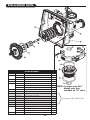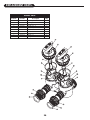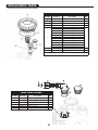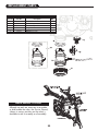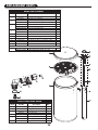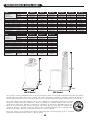
1
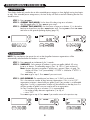
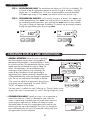
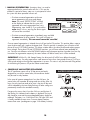
Impression Plus Series
®
Metered Water Softeners
For Models:
• IMP-844
• IMP-948
• IMP-1044
• IMP-1054
• IMP-1248
• IMP-1354
For Cabinet Models:
• IMPC-835
• IMPC-935
• IMPC-1035
TABLE OF CONTENTS
Preinstallation Instructions for Dealers . . . . . . . . . . . . . . . . . . . . . . . . . . . .3
Bypass Valve . . . . . . . . . . . . . . . . . . . . . . . . . . . . . . . . . . . . . . . . . . . . . . . .3-4
Installation . . . . . . . . . . . . . . . . . . . . . . . . . . . . . . . . . . . . . . . . . . . . . . . . . . .7
Programming Procedures . . . . . . . . . . . . . . . . . . . . . . . . . . . . . . . . . . . . . .8-9
Operating Displays and Instructions . . . . . . . . . . . . . . . . . . . . . . . . . . . .9-11
Start-up Instructions . . . . . . . . . . . . . . . . . . . . . . . . . . . . . . . . . . . . . . . .12-13
Troubleshooting Guide . . . . . . . . . . . . . . . . . . . . . . . . . . . . . . . . . . . . . .14-17
Replacement Parts . . . . . . . . . . . . . . . . . . . . . . . . . . . . . . . . . . . . . . . . . .18-27
Specifications . . . . . . . . . . . . . . . . . . . . . . . . . . . . . . . . . . . . . . . . . . . . . . . .28
Warranty . . . . . . . . . . . . . . . . . . . . . . . . . . . . . . . . . . . . . . . . . . . . . . . . . . . .29
Quick Reference Guide . . . . . . . . . . . . . . . . . . . . . . . . . . . . . . . . . . . . . . . .32
YOUR WATER TEST
Hardness
Iron
pH
*Nitrates
Manganese
Sulphur
Total Dissolved Solids
gpg
ppm
number
ppm
ppm
yes/no
*Over 10 ppm may be harmful for human consumption. Water
conditioners do not remove nitrates or coliform bacteria, this
requires specialized equipment.
Your Impression Plus Series water conditioners are precision built, high quality products. These units will deliver
conditioned water for many years to come, when installed and operated properly. Please study this manual carefully
and understand the cautions and notes before installing. This manual should be kept for future reference. If you have
any questions regarding your water conditioner, contact your local dealer or Water-Right at the following:
Water-Right, Inc.
1900 Prospect Court • Appleton, WI 54914
Phone: 920-739-9401 • Fax: 920-739-9406
PREINSTALLATION INSTRUCTIONS FOR DEALERS:
The manufacturer has preset the water treatment unit’s sequence of cycles, cycle times, salt dose,
exchange capacity and salt dose refill time.
The dealer should read this page and guide the installer regarding hardness, day override, and time of
regeneration, before installation.
For the installer, the following must be used:
• Program Installer Settings: Hardness, Day Override (preset to 12 days), and Time of
Regeneration (preset to 2 a.m., with brine tank refill to occur four hours prior; see Operating
Displays and Instructions for more details)
• Read Normal Operating Displays
• Set Time of Day
• Read Power Loss & Error Display
• Be sure system and installation are in compliance with all state and local laws and regulations.
For the homeowner, please read operating displays and instructions.
WATER SOFTENERS:
During operation, the normal user displays are time of day or gallons remaining before regeneration
will occur.
Days remaining is an optional display but is not normally used. Each of these can be viewed by pressing
NEXT to scroll through them. When stepping through any displays or programming, if no buttons are
pressed within 5 minutes, the display returns to a normal user display. Any changes made prior to the
5 minute time out are incorporated.
To quickly exit any Programming, Installer Settings, etc., press SET CLOCK. Any changes made prior to
the exit are incorporated. If desired, two regenerations within 24 hours are possible with a return to
the preset program. To do a double regeneration:
1. Press the REGEN button once. “REGEN TODAY” will flash on the display.
2. Press and hold the REGEN button for three seconds until a regeneration begins.
Once the valve has completed the immediate regeneration, the valve will regenerate one more time
at the preset.
BYPASS VALVE:
The bypass valve is typically used to isolate the control valve from the plumbing system’s water pressure
in order to perform control valve repairs or maintenance. The 1" full flow bypass valve incorporates four
positions, including a diagnostic position that allows a service technician to have pressure to test a system
while providing untreated bypass water to the building. Be sure to install bypass valve onto main control
valve, before beginning plumbing. Or, make provisions in the plumbing system for a bypass. The bypass
body and rotors are glass-filled Noryl® and the nuts and caps are glass-filled polypropylene. All seals are
self-lubricating EPDM to help prevent valve seizing after long periods of non-use. Internal “O” Rings can
easily be replaced if service is required.
The bypass consists of two interchangeable plug valves that are operated independently by red arrow
shaped handles. The handles identify the direction of flow. The plug valves enable the bypass valve to
operate in four positions.
3
1. NORMAL OPERATION POSITION: The inlet and outlet handles point in the direction of flow
indicated by the engraved arrows on the control valve. Water flows through the control valve for normal
operation of a water softener. During the regeneration cycle this position provides regeneration water to
the unit, while also providing untreated water to the distribution system (Fig. 1).
2. BYPASS POSITION: The inlet and outlet handles point to the center of the bypass. The system is
isolated from the water pressure in the plumbing system. Untreated water is supplied to the building
(Fig. 2).
3. DIAGNOSTIC POSITION: The inlet handle points toward the control valve and the outlet handle
points to the center of bypass valve. Untreated supply water is allowed to flow to the system and to
the building, while not allowing water to exit from the system to the building (Fig. 3). This allows the
service technician to draw brine and perform other tests without the test water going to the building.
NOTE: The system must be rinsed before returning the bypass valve to the normal position.
4. SHUT OFF POSITION: The inlet handle points to the center of the bypass valve and the outlet
handle points away from the control valve. The water is shut off to the building. The water treatment
system will depressurize upon opening a tap in the building. A negative pressure in the building
combined with the softener being in regeneration could cause a siphoning of brine into the building.
If water is available on the outlet side of the softener, it is an indication of water bypassing the
system (Fig. 4) (i.e. a plumbing cross-connection somewhere in the building).
NORMAL OPERATION POSITION
BYPASS POSITION
Figure 1
Figure 2
DIAGNOSTIC POSITION
SHUT OFF POSITION
Figure 3
Figure 4
4
INSTALLATION:
GENERAL INSTALLATION & SERVICE WARNINGS
The control valve, fittings and/or bypass are designed to accommodate minor plumbing misalignments.
There is a small amount of “give” to properly connect the piping, but the water softener is not designed to
support the weight of the plumbing.
Do not use Vaseline, oils, other hydrocarbon lubricants or spray silicone anywhere. A silicone lubricant may
be used on black “O” Rings, but is not necessary. Avoid any type of lubricants, including silicone, on red
or clear lip seals.
Do not use pipe dope or other sealants on threads. Teflon® tape must be used on the threads of the 1" NPT
inlet and and outlet, the brine line connection at the control valve, and on the threads for the drain line
connection. Teflon® tape is not used on the nut connections or caps because “O” Ring seals are used.
The nuts and caps are designed to be unscrewed or tightened by hand or with the special plastic Service
Wrench, #CV3193-01. If necessary, pliers can be used to unscrew the nut or cap. Do not use a pipe wrench
to tighten nuts or caps. Do not place screwdriver in slots on caps and/or tap with a hammer.
SITE
•
•
•
•
REQUIREMENTS
water pressure – 30 -100 psi
water temperature – 33-100°F (0.5-37.7°C)
electrical – 115/120V, 60Hz uninterrupted outlet
the tank should be on a firm level surface
WELL WATER INSTALLATION
• current draw is 0.5 amperes
• the plug-in transformer is for dry locations only
MUNICIPAL INSTALLATION
1. The distance between the drain and the water conditioner should be as short as possible.
2. Since salt must be periodically added to the brine tank, it should be located where it is
easily accessible.
3. Do not install any water conditioner with less than 10 feet of piping between its outlet and the inlet
of a water heater.
4. Do not position unit where it or its connections (including the drain and overflow lines) will ever be
subjected to room temperatures under 33° F.
5. Do not subject the tank to any vacuum, as this may cause an “implosion” and could result in leaking. If
there is a possibility a vacuum could occur, please make provision for a vacuum breaker in the installation.
5
6. INLET/OUTLET PLUMBING: Be sure to install bypass valve onto main control valve before
beginning plumbing. Make provisions to bypass outside hydrant and cold hard water lines at this
time. Install an inlet shutoff valve and plumb to the unit’s bypass valve inlet located at the right rear
as you face the unit. There are a variety of installation fittings available. They are listed under
Installation Fitting Assemblies, page 24-25. When assembling the installation fitting package (inlet
and outlet), connect the fitting to the plumbing system first and then attach the nut, split ring and “O”
Ring. Heat from soldering or solvent cements may damage the nut, split ring or “O” Ring. Solder
joints should be cool and solvent cements should be set before installing the nut, split ring and “O”
Ring. Avoid getting solder flux, primer, and solvent cement on any part of the “O” Rings, split rings,
bypass valve or control valve. If the building’s electrical system is grounded to the plumbing, install a
copper grounding strap from the inlet to the outlet pipe. Plumbing must be done in accordance with
all applicable local and state codes.
7. INSTALLING GROUND: To maintain an electrical ground in
metal plumbing of a home’s cold water piping (such as a copper
plumbing system), install a ground clamp or jumper wiring.
NOTE: If replacing an existing softener, also replace the ground
clamps/wire. If removing a softener, replace the piping with the
same type of piping as the original to assure plumbing integrity
and grounding.
8. DRAIN LINE: First, be sure that the drain can handle the backwash rate of the system. Solder joints
near the drain must be done prior to connecting the drain line flow control fitting. Leave at least 6"
between the drain line flow control fitting and solder joints. Failure to do this could cause interior
damage to the flow control. Install a 1/2" I.D. flexible plastic tube to the Drain Line Assembly or
discard the tubing nut and use the 3/4" NPT fitting for rigid pipe (recommended). If the backwash
rate is greater than 7 gpm, use a 3/4" drain line. Where the drain line is elevated but empties into
a drain below the level of the control valve, form a 7" loop at the discharge end of the line so that
the bottom of the loop is level with the drain connection on the control valve. This will provide an
adequate anti-siphon trap. Piping the drain line overhead <10 ft is normally not a problem. Be
sure adequate pressure is available (40-60 psi is recommended). Where the drain empties into an
overhead sewer line, a sink-type trap must be used with appropriate air gap (see drawing). Run
drain tube to its discharge point in accordance with plumbing codes. Pay special attention to codes
for air gaps and anti-siphon devices.
Typical Drain Line Installations
6
9. BRINE TANK CONNECTION: Install the 3/8" O.D. polyethylene tube from the Refill Elbow to the
Brine Valve in the brine tank.
10. OVERFLOW LINE CONNECTION: An overflow drain line is recommended where a brine
overflow could damage furnishings or the building structure. Your softener is equipped with a brine
tank safety float which greatly reduces the chance of an accidental brine overflow. In the event of a
malfunction, however, an overflow line connection will direct the “overflow” to the drain instead of
spilling on the floor where it could cause considerable damage. This fitting is an elbow on the side
of the brine tank. Attach a length of 1/2" I.D. tubing to fitting and run to drain. Do not elevate
overflow line higher than 3" below bottom of overflow fitting. Do not “tie” this tube into the drain
line of the control valve. Overflow line must be a direct, separate line from overflow fitting to drain,
sewer, or tub. Allow an air gap as per the drain line instructions.
CAUTION: Never insert a drain line into a drain, sewer line,
or trap. Always allow an air gap of 1-1/2" or
twice the pipe diameter, whichever is greater,
between the drain line and the wastewater to
prevent the possibility of sewage being backsiphoned into the conditioner.
7
PROGRAMMING PROCEDURES:
1. Set time of day:
Time of day should only need to be set after extended power outages or when daylight saving time begins
or ends. If an extended power outage occurs, the time of day will flash on and off indicating that the time
should be reset.
STEP 1 – Press SET CLOCK.
STEP 2 – CURRENT TIME (HOUR): Set the hour of the day using + or — buttons.
AM/PM toggles after 12. Press NEXT to go to step 3.
STEP 3 – CURRENT TIME (MINUTES): Set the minutes using + or — buttons. If it is desired to
back up to the previous step press REGEN button once. Pressing NEXT will exit SET CLOCK
and return to the general operating display (page 10).
1
2
3
2. Programming:
NOTE: The manufacturer has preset the unit so that the gallons between regenerations will be
automatically calculated after the hardness is entered.
STEP 1 – Press NEXT and + simultaneously for 3 seconds.
STEP 2 – HARDNESS: Set the amount of hardness in grains per gallon (default 20) using
the + or — buttons. The allowable range is from 1 to 150 in 1 grain increments.
Note: Increase the grains per gallon if soluble iron is present (1ppm = 4 gpg). This
display will show “–nA– (not available)” if “FILTER” is selected or if “AUTO” is
not factory set.
Press NEXT to go to step 3. Press REGEN if you want to exit.
STEP 3 – DAY OVERRIDE: The manufacturer has factory set 12 DAYS as the default.
This is the maximum number of days between regenerations. If this is set to “OFF”,
regeneration initiation is based solely on gallons used. If any number is set (allowable
range from 1 to 28), a regeneration initiation will be called for on that day even if a
sufficient number of gallons were not used to call for a regeneration.
Set Day Override using + or — buttons (12 is recommended):
• set number of days between regeneration (1 to 28); or
• set to “OFF”.
Press NEXT to go to step 4. Press REGEN if you need to return to the previous step.
1
2
3
8
2. Programming cont’d:
STEP 4 – REGENERATION HOUR: The manufacturer has factory set 2:00 A.M. as the default. This
is the hour of day for regeneration and can be reset by using + or — buttons. “AM/PM”
toggles after 12. The default time is 2:00 a.m. (recommended for a normal household).
Press NEXT to go to step 5. Press REGEN if you need to return to the previous step.
STEP 5 – REGENERATION MINUTES: Set the minutes using + or — buttons. Press NEXT to exit
installer programming. Press REGEN if you need to return to the previous step. To initiate
an immediate manual regeneration, press and hold the REGEN button for three seconds.
The system will begin to regenerate immediately. The control may be manually stepped
through the regeneration cycles by pressing REGEN.
4
5
OPERATING DISPLAYS AND INSTRUCTIONS:
1. GENERAL OPERATION: When the system is operating,
one of three displays may be shown. Pressing NEXT will
alternate between the displays. One of the displays is always
the current time of day. The second display shows the current
treated water flow rate through the system in Gallons Per
Minute. The third display is one of the following: days
remaining or volume remaining. Days remaining is the
number of days left before the system goes through a
regeneration cycle. Capacity remaining is the gallons that
will be treated before the system goes through a regeneration
cycle. The user can scroll between the displays as desired.
GENERAL OPERATION DISPLAYS
If the system has called for a regeneration that will occur
at the preset time of regeneration, the words “REGEN
TODAY” will appear on the display.
If a water meter is installed, the word “Softening” or “Filtering” flashes on the
display when water is being treated (i.e. water is flowing through the system).
2. REGENERATION MODE: Typically a system is set to regenerate at
a time of no water use. If there is a demand for water when the
system is regenerating, untreated water will be delivered. When the
system begins to regenerate, the display will change to include
information about the step of the regeneration process and the time
remaining for that step to be completed. The system runs through the
steps automatically and will reset itself to provide treated water when
the regeneration has been completed.
9
REGENERATION
MODE
3. MANUAL REGENERATION: Sometimes there is a need to
regenerate before the control valve calls for it. This may be
needed if a period of heavy water use is anticipated or when
the system has been operated without salt.
• To initiate a manual regeneration at the next
preset regeneration time, press and release
REGEN. The words “REGEN TODAY” will flash
on the display to indicate that the system will
regenerate at the next regeneration time (set in
Programming, steps 4 and 5). If you pressed the
REGEN button in error, pressing the button again
will cancel the command.
MANUAL REGENERATION
• To initiate a manual regeneration immediately, press and hold
the REGEN button for three seconds. The system will begin to
regenerate immediately. This command cannot be cancelled.
Once a manual regeneration is initiated, the unit will go into the FILL position. This position allows water to
enter the brine tank until it reaches the proper level. Once this position is complete, you will notice a 240
Minute (4 hours) SOFTENING position. This 4-hour window allows the salt to dissolve and achieve proper
brine strength. During these FILL and SOFTENING positions, you will have softened water available for
use. Once the unit advances to the BACKWASH position and subsequent positions thereafter (see Start Up
Instructions for regeneration sequence), the water softener will deliver water, but it will be untreated.
IMPORTANT: With the Dry Salt Storage Feature, the brine tank will refill 4 hours before the actual
regeneration occurs. You may experience a small amount of noise for a short period of time at 10:00 p.m.
(with typical setting) on the night that regeneration is to occur. This noise is only the brine tank filling and at
no time during this process will you be without treated water.
4. POWER LOSS AND BATTERY REPLACEMENT:
The AC transformer comes with a 15 foot power cord and is
designed for use with the control valve; the transformer should
only be used in a dry location.
In the event of a power outage that is less than 24 hours, the
control valve will remember all settings and time of day. After 24
hours, the only item that needs to be reset is the time of day and
will be indicated by the time of day flashing. All other settings are
permanently stored in the nonvolatile memory.
If a power loss occurs that is less than 24 hours and the time of
day flashes, this indicates that the battery is depleted. The time of
day should be reset and the non-rechargeable battery should be
replaced. The battery is a 3 Volt Lithium Coin Cell type 2032 and
is readily available at most stores. To access battery location,
remove front cover (see diagram on page 14 for battery location).
10
BATTERY REPLACEMENT
5. ERROR MESSAGE: If the word “ERROR” and a number are
alternately flashing on the display record the number and contact
the dealer for help. This indicates that the control valve was not
able to function properly.
ERROR
6. BRINE TANK MAINTENANCE AND SALT: Refill the brine tank as necessary, making sure at
least 1/3 of the brine tank is full at all times. Without proper salt levels, the water softener may
not operate properly.
Because “typical” settings of this water softener include a dry salt storage feature (no water in
brine tank between regeneration), the manufacturer recommends the use of solar salt for best
results. The brine tank is manufactured for the use of solar, pellets or rock salt. If pellet or rock
salt is used, a cleaning of the brine tank every six months is recommended. If the dry salt
storage feature is not being utilized, block salt may be used.
CAUTION: The manufacturer does not recommend the use of any
resin cleaners, nor placement of any resin cleaners into
the brine tank. This may be harmful to the water
softener and for human consumption. Consult dealer
for proper cleaning instructions.
11
START-UP INSTRUCTIONS:
FLUSHING OF SYSTEM:
To flush the system of any debris and air after installation is complete, please perform the following steps:
1. Rotate bypass handles to the bypass mode (see Fig. 2 of page 4).
2. Turn on inlet water and check for leaks in the newly installed plumbing.
3. Fully open a cold water faucet, preferable at a laundry sink or bathtub without an aerator.
4. Wait two to three minutes or until water runs clear, then turn water off and follow
start-up instructions.
System regeneration sequence is in the following order. (If it is desired to change this sequence, please refer
to the Dealer Manual or contact the manufacturer.)
1) BRINE TANK REFILL
2) 4 HOURS (240 minutes) OF SOFTENING MODE WHILE SALT IS DISSOLVING
3) BACKWASH
4) BRINE DRAW AND SLOW RINSE
5) FAST RINSE
6) END (return to service)
The system is now ready for filling with water and for testing.
1. With the softener in the bypass mode (Fig. 2 on page 4) and the control valve in normal operation
where the display shows either the time of day or the gallons remaining, manually add 3" of water to
the regenerant tank.
NOTE: If too much water is put into the brine tank during softener start up, it could result in a
“salty water” complaint after the first regeneration.
During the first regeneration the unit will draw out the initial volume of brine/regenerant and refill it
with the correct preset amount.
2. With the softener in bypass mode, press and hold the REGEN button until the motor starts. Release button.
The display reads “FILL” and the remaining time in this step is counting down. Since the regenerant tank
was already filled in Step 1 press REGEN again and the display will read SOFTENING 240 (During a full
regeneration this will be a 4 hour period for salt to dissolve). Press REGEN again to put the valve into
“BACKWASH.” Once valve has stopped in position, unplug the transformer so that the valve will not cycle
to the next position. Open the inlet handle of the bypass valve very slightly allowing water to fill the tank
slowly in order to expel air.
CAUTION: If water flows too rapidly, there will be a loss of
media to the drain.
3. When the water is flowing steadily to the drain without the presence of air, slowly open the inlet valve.
Restore power and momentarily press the REGEN button to advance the control to the “BRINE” position.
4. The bypass is now in the diagnostic mode (Fig. 3 on page 4). Check to verify that water is being
drawn from regenerant tank with no air leaks or bubbles in the brine line. There should be a slow flow
to the drain.
12
5. Momentarily press REGEN again until the display reads “RINSE.” There should be a rapid flow to the
drain. Unplug transformer to keep the valve in the “RINSE” position. Allow to run until steady, clear
and without air. While the unit is rinsing, load the brine tank with water softener salt (refer to
page 9, Brine Tank Maintenance and Salt). Restore power.
6. Place bypass valve in the normal operating mode (Fig. 1 on page 4) by opening the outlet bypass
handle. Press REGEN and the unit will return to the service position with time of day being displayed.
7. CONDITIONING OF MEDIA:
To flush any remaining debris and air from the system again:
1. Full open a cold water faucet, preferably at a laundry sink or bathtub without an aerator.
2. Wait two to three minutes or until water runs clear, then turn water off.
3. Turn on hot water and check for air, then turn water off after air is discharged.
8. SANITIZING OF UNIT UPON INSTALLATION AND AFTER SERVICE:
At this time, it is advised to sanitize the softener:
1. Open brine tank and remove brine well cover.
2. Pour 1 oz. of household bleach into the softener brine well.
3. Replace brine well cover.
NOTE: Avoid pouring bleach directly onto the safety float components in the brine well.
Unit sanitizing will be complete when the first cycle is run and the bleach is flushed from the softener.
9. Check time of day. Start-up is now complete.
13
TROUBLESHOOTING GUIDE:
PROBLEM
1. No display on
PC board
2. PC board does not
display correct time
of day
3. Display does not
indicate that water is
flowing. Refer to user
instructions for how the
display indicates water
is flowing.
4. Control valve
regenerates at wrong
time of day
5. Time of day flashes on
and off
CAUSE
CORRECTION
A. No power at electric outlet
A. Repair outlet or use working outlet
B. Control valve power adapter not plugged into
outlet or power cord end not connected to PC
board connection
B. Plug power adapter into outlet or connect
power cord end to PC board connection
C. Improper power supply
C. Verify proper voltage is being delivered to
PC board
D. Defective power adapter
D. Replace power adapter
E. Defective PC board
E. Replace PC board
A. Power adapter plugged into electric outlet
controlled by light switch
A. Use uninterrupted outlet
B. Tripped breaker switch and/or tripped GFI
B. Reset breaker switch and/or GFI switch
C. Power outage
C. Reset time of day. If PC board has battery
back up present the battery may be depleted.
See front cover and drive assembly drawing
for instructions.
D. Defective PC board
D. Replace PC board
A. Bypass valve in bypass position
A. Turn bypass handles to place bypass in
service position
B. Meter is not connected to meter connection on
PC board
B. Connect meter to three pin connection labeled
METER on PC board
C. Restricted/stalled meter turbine
C. Remove meter and check for rotation or
foreign material
D. Meter wire not installed securely into three
pin connector
D. Verify meter cable wires are installed securely
into three pin connector labeled METER
E. Defective meter
E. Replace meter
F. Defective PC board
F. Replace PC board
A. Power outage
A. Reset time of day. If PC board has battery
back up present the battery may be depleted.
See front cover and drive assembly drawing
for instructions.
B. Time of day not set correctly
B. Reset to correct time of day
C. Time of regeneration set incorrectly
C. Reset regeneration time
D. Control valve set at “on 0” (immediate
regeneration)
D. Check programming setting and reset to
NORMAL (for a delayed regen time)
E. Control valve set at “NORMAL + on 0”
(delayed and/or immediate)
E. Check programming setting and reset to
NORMAL (for a delayed regen time)
A. Power outage
A. Reset time of day. If PC board has battery
back up present the battery may be depleted.
See front cover and drive assembly drawing
for instructions.
6. Control valve does not
regenerate automatically A. Broken drive gear or drive cap assembly
when the correct button(s)
is depressed and held.
B. Broken piston rod
For timeclock valves the
buttons are ▲ & ▼.
For all other valves the
C. Defective PC board
button is REGEN.
14
A. Replace drive gear or drive cap assembly
B. Replace piston rod
C. Defective PC board
PROBLEM
7. Control valve does not
regenerate automatically
but does when the
correct button(s) is
depressed and held. For
timeclock valves the
buttons are ▲ & ▼.
For all other valves the
button is REGEN.
8. Hard or untreated
water is being
delivered
9. Control valve uses too
much regenerant
10. Residual regenerant
being delivered to
service
11. Excessive water in
regenerant tank
CAUSE
CORRECTION
A. Bypass valve in bypass position
A. Turn bypass handles to place bypass in
service position
B. Meter is not connected to meter connection on
PC board
B. Connect meter to three pin connection labeled
METER on PC board
C. Restricted/stalled meter turbine
C. Remove meter and check for rotation or
foreign material
D. Incorrect programming
D. Check for programming error
E. Meter wire not installed securely into three
pin connector
E. Verify meter cable wires are installed securely
into three pin connector labeled METER
F. Defective meter
F. Replace meter
G. Defective PC board
G. Replace PC board
A. Bypass valve is open or faulty
A. Fully close bypass valve or replace
B. Media is exhausted due to high water usage
B. Check program settings or diagnostics for
abnormal water usage
C. Meter not registering
C. Remove meter and check for rotation or
foreign material
D. Water quality fluctuation
D. Test water and adjust program
values accordingly
E. No regenerant or low level of regenerant in
regenerant tank
E. Add proper regenerant to tank
F. Control fails to draw in regenerant
F. Refer to Troubleshooting Guide number 12
G. Insufficient regenerant level in regenerant tank
G. Check refill setting in programming. Check
refill flow control for restrictions or debris and
clean or replace
H. Damaged seal/stack assembly
H. Replace seal/stack assembly
I. Control valve body type and piston type
mix matched
I. Verify proper control valve body type and
piston type match
J. Fouled media bed
J. Replace media bed
A. Improper refill setting
A. Check refill setting
B. Improper program settings
B. Check program setting to make sure
they are specific to the water quality and
application needs
C. Control valve regenerates frequently
C. Check for leaking fixtures that may be
exhausting capacity or system is undersized
A. Low water pressure
A. Check incoming water pressure – water
pressure must remain at minimum of 25 psi
B. Incorrect injector size
B. Replace injector with correct size for
the application
C. Restricted drain line
C. Check drain line for restrictions or debris
and clean
A. Improper program settings
A. Check refill setting
B. Plugged injector
B. Remove injector and clean or replace
C. Drive cap assembly not tightened in properly
C. Retighten the drive cap assembly
D. Damaged seal/stack assembly
D. Replace seal/stack
E. Restricted or kinked drain line
E. Check drain line for restrictions or debris and
or unkink drain line
F. Plugged backwash flow controller
F. Remove backwash flow controller and clean
or replace
G. Missing refill flow controller
G. Replace refill flow controller
15
TROUBLESHOOTING GUIDE cont’d:
PROBLEM
12. Control valve fails to
draw in regenerant
13. Water running to
drain
14. E1, Err – 1001,
Err – 101 =
Control unable
to sense motor
movement
15. E2, Err – 1002, Err –
102 = Control valve
motor ran too short
and was unable to
find the next cycle
position and stalled
CAUSE
CORRECTION
A. Injector is plugged
A. Remove injector and clean or replace
B. Faulty regenerant piston
B. Replace regenerant piston
C. Regenerant line connection leak
C. Inspect regenerant line for air leak
D. Drain line restriction or debris cause excess
back pressure
D. Inspect drain line and clean to
correct restriction
E. Drain line too long or too high
E. Shorten length and or height
F. Low water pressure
F. Check incoming water pressure – water
pressure must remain at minimum of 25 psi
A. Power outage during regeneration
A. Upon power being restored control will finish
the remaining regeneration time. Reset time of
day. If PC board has battery back up present
the battery may be depleted. See front cover
and drive assembly drawing for instructions.
B. Damaged seal/stack assembly
B. Replace seal/stack assembly
C. Piston assembly failure
C. Replace piston assembly
D. Drive cap assembly not tightened in properly
D. Retighten the drive cap assembly
A. Motor not inserted full to engage pinion, motor
wires broken or disconnected
A. Disconnect power, make sure motor is fully
engaged, check for broken wires, make sure
two pin connector on motor is connected to the
two pin connection on the PC board labeled
MOTOR. Press NEXT and REGEN buttons for
3 seconds to resynchronize software with piston
position or disconnect power supply from PC
board for 5 seconds and then reconnect.
B. Properly snap PC board into drive bracket and
then Press NEXT and REGEN buttons for 3
B. PC board not properly snapped into drive bracket
seconds to resynchronize software with piston
position or disconnect power supply from PC
board for 5 seconds and then reconnect.
C. Missing reduction gears
C. Replace missing gears
A. Foreign material is lodged in control valve
A. Open up control valve and pull out piston
assembly and seal/stack assembly for
inspection. Press NEXT and REGEN buttons for
3 seconds to resynchronize software with piston
position or disconnect power supply from PC
board for 5 seconds and then reconnect.
B. Mechanical binding
B. Check piston and seal/stack assembly, check
reduction gears, check drive bracket and main
drive gear interface. Press NEXT and REGEN
buttons for 3 seconds to resynchronize software
with piston position or disconnect power supply
from PC board for 5 seconds and then reconnect.
C. Main drive gear too tight
C. Loosen main drive gear. Press NEXT and
REGEN buttons for 3 seconds to resynchronize
software with piston position or disconnect
power supply from PC board for 5 seconds
and then reconnect.
D. Improper voltage being delivered to PC board
D. Verify that proper voltage is being supplied.
Press NEXT and REGEN buttons for 3 seconds
to resynchronize software with piston position
or disconnect power supply from PC board for
5 seconds and then reconnect.
16
PROBLEM
CAUSE
CORRECTION
A. Motor failure during a regeneration
16. E3, Err – 1003, Err –
103 = Control valve
B. Foreign matter built up on piston and stack
motor ran too long and
assemblies creating friction and drag enough
was unable to find the
to time out motor
next cycle position
C. Drive bracket not snapped in properly and out
enough that reduction gears and drive gear do
not interface
17. E4, Err – 1004, Err –
A. Drive bracket not snapped in properly and out
104 = Control valve
enough that reduction gears and drive gear do
motor ran too long
not interface
and timed out trying
to reach home position
18. Err -1006, Err – 106,
Err - 116 = MAV/
SEPS/ NHBP/ AUX
MAV valve motor ran
too long and unable
to find the proper
park position
Separate Source = SEPS
Auxiliary MAV = AUX
MAV
A. Snap drive bracket in properly then Press
NEXT and REGEN buttons for 3 seconds to
resynchronize software with piston position
or disconnect power supply from PC board
for 5 seconds and then reconnect.
B. MAV/NHBP motor wire not connected to
PC board
B. Connect MAV/NHBP motor to PC board two
pin connection labeled DRIVE. Press NEXT and
REGEN buttons for 3 seconds to resynchronize
software with piston position or disconnect
power supply from PC board for 5 seconds
and then reconnect.
C. MAV/NHBP motor not fully engaged with
reduction gears
C. Properly insert motor into casing, do not force
into casing Press NEXT and REGEN buttons for
3 seconds to resynchronize software with piston
position or disconnect power supply from PC
board for 5 seconds and then reconnect.
D. Foreign matter built up on piston and stack
assemblies creating friction and drag enough
to time out motor
D. Replace piston and stack assemblies. Press
NEXT and REGEN buttons for 3 seconds to
resynchronize software with piston position
or disconnect power supply from PC board
for 5 seconds and then reconnect.
A. Open up MAV/NHBP valve and check piston
and seal/ stack assembly for foreign material.
Press NEXT and REGEN buttons for 3 seconds
to resynchronize software with piston position
or disconnect power supply from PC board for
5 seconds and then reconnect.
B. Check piston and seal/stack assembly, check
reduction gears, drive gear interface, and
check MAV/NHBP black drive pinion on
motor for being jammed into motor body.
Press NEXT and REGEN buttons for 3 seconds
to resynchronize software with piston position
or disconnect power supply from PC board for
5 seconds and then reconnect.
Motorized Alternating
Valve = MAV
Separate Source = SEPS
C. Snap drive bracket in properly then Press
NEXT and REGEN buttons for 3 seconds to
resynchronize software with piston position
or disconnect power supply from PC board
for 5 seconds and then reconnect.
A. Press NEXT and REGEN buttons for 3 seconds
to resynchronize software with piston position
or disconnect power supply from PC board for
5 seconds and then reconnect. Then reprogram
valve to proper setting
19. Err – 1007, Err – 107,
Err - 117 = MAV/
SEPS/NHBP/AUX
A. Foreign material is lodged in
MAV valve motor ran
MAV/NHBP valve
too short (stalled)
while looking for
proper park position
No Hard Water Bypass =
NHBP
B. Replace piston and stack assemblies. Press
NEXT and REGEN buttons for 3 seconds to
resynchronize software with piston position
or disconnect power supply from PC board
for 5 seconds and then reconnect.
A. Control valve programmed for ALT A or B,
nHbP, SEPS, or AUX MAV with out having
a MAV or NHBP valve attached to operate
that function
Motorized Alternating
Valve = MAV
No Hard Water Bypass =
NHBP
A. Check motor connections then Press NEXT and
REGEN buttons for 3 seconds to resynchronize
software with piston position or disconnect
power supply from PC board for 5 seconds
and then reconnect.
B. Mechanical binding
Auxiliary MAV = AUX
MAV
17
REPLACEMENT PARTS:
FRONT COVER AND DRIVE ASSEMBLY
Item No.
1
Part No.
Description
Qty.
®
CV3540-A
Black Impression cover
1
CV3540-W-A
Gray Impression® cover
1
CV3540P-A
Black Impression Plus® cover
1
CV3540P-W-A
Gray Impression Plus® cover
1
2
CV3107-1
Motor
1
3
CV3106-1
Drive bracket & spring clip
1
4
CV3579WI
PC board, CC
1
5
CV3110
Drive gear, 12 x 36
3
6
CV3109
Drive gear cover
1
7
CV3002CC
Drive assembly, CC
-
CV3186
Transformer, 110V-12V
1
CV3543
Optional weather cover
1
NOTE: Battery Location
4
1
6
5
3
2
7
18
REPLACEMENT PARTS:
1
13
14
5
4
7
9
3
8
2
10
11
12
PISTON ASSEMBLY
Item No.
Part No.
Description
Qty.
CV3005
1" spacer stack assembly
1
CV3430
1.25" spacer stack assembly
1
2
CV3004
Drive cap assembly
1
3
CV3135
O-ring 228
1
CV3011
1" piston assembly downflow
1
1
4
1" piston assembly upflow
1
CV3407
1.25" piston assembly downflow
1
5
CV3174
Regenerant piston
1
6
CV3180
O-ring 337
1
7
CV3105
O-ring 215
1
CV3556
Screw, 1/4 - 20x1-1/2 18-8SS
1
8
9
CV3011-01
CCI-00318337 Nut, 1/4 - 20 HEX 18-8SS
10
CV3016
11
12
13
14
1
QC2 clamp assembly (includes screw & nut)
1
CV3452
O-ring 230
1
CV3015
WS1 QC2 Tank adapter assembly (includes O-rings)
1
CV3001-04
1" body assembly downflow
1
CV3001UP
1" body assembly upflow
1
CV3020
1.25" body assembly downflow
1
CV3541
Drive backplate
1
19
6
7
NOTE: For Impression Plus ®
Models only. Not
available on 1¼" valve.
For Impression Plus® Models Only
REPLACEMENT PARTS:
BYPASS VALVE
Item No.
Part No.
1
2
3
4
5
6
7
8
9
10
CV3151
CV3150
CV3105
CV3145
CV3146
CV3147
CV3148
CV3152
CV3155
CV3156
Description
Qty.
Nut, 1" quick connect
Split ring
O-ring 215
Bypass rotor, 1"
Bypass cap
Bypass handle
Bypass rotor seal retainer
O-ring 135
O-ring 112
O-ring 214
2
2
2
2
2
2
2
2
2
2
20
REPLACEMENT PARTS:
INJECTOR ASSEMBLIES
Item No.
Part No.
1
2
3
4
CV3176
CV3152
CV3177-01
CV3010-1Z
CV3010-1A
CV3010-1B
CV3010-1C
CV3010-1D
CV3010-1E
CV3010-1F
CV3010-1G
CV3010-1H
CV3010-1I
CV3010-1J
CV3010-1K
CV3170
CV3171
5
not shown
not shown
Description
Injector cap
O-ring 135
Injector screen
Injector assembly plug
A injector assembly, BLACK
B injector assembly, BROWN
C injector assembly, VIOLET
D injector assembly, RED
E injector assembly, WHITE
F injector assembly, BLUE
G injector assembly, YELLOW
H injector assembly, GREEN
I injector assembly, ORANGE
J injector assembly, LIGHT BLUE
K injector assembly, LIGHT GREEN
O-ring 011, lower
O-ring 013, upper
Qty.
1
1
1
1
1
*
*
* The injector plug and the injector each use one lower and one upper o-ring
BRINE ELBOW ASSEMBLY
Item No.
Part No.
1
CV3195-01
CH4615
CS1197
CJCPG-6PBLK
CH4613
CV3163
2
3
4
5
6
Description
Refill port plug assembly
Elbow locking clip
Tube insert, 3/8"
Nut, 3/8"
Elbow cap, 3/8"
O-ring 019
Qty.
1
1
1
1
1
1
21
REPLACEMENT PARTS:
DRAIN LINE ASSEMBLY 3/4"
Item No.
Part No.
1
CH4615
2
CPKP10TS8-BULK
3
CV3192
4
CV3158-01
5
CV3163
6
7
8
CV3159-01
Description
Elbow locking clip
1
Optional insert, 5/8" tube
1
Optional nut, 3/4" drain elbow
1
Drain elbow, 3/4" NPT with O-ring
1
O-ring 019
1
DLFC retainer assembly
1
CV3162-007
0.7 DLFC for 3/4" elbow
CV3162-010
1.0 DLFC for 3/4" elbow
CV3162-013
1.3 DLFC for 3/4" elbow
CV3162-017
1.7 DLFC for 3/4" elbow
CV3162-022
2.2 DLFC for 3/4" elbow
CV3162-027
2.7 DLFC for 3/4" elbow
CV3162-032
3.2 DLFC for 3/4" elbow
CV3162-042
4.2 DLFC for 3/4" elbow
CV3162-053
5.3 DLFC for 3/4" elbow
CV3331
Qty.
1
Drain elbow and retainer assembly
Items 2 and 3, nut and insert are only used with 1/2" I.D.
by 5/8" O.D. polytubing. For other piping material, the
3/4" NPT is used.
3/4" NPT
Proper DLFC orientation
directs water flow towards
the washer face with
rounded edge and lettering.
Water
Flow
22
REPLACEMENT PARTS:
WATER METER & METER PLUG
Item No.
Part No.
Description
Qty.
1
CV3151
Nut, 1" QC
1
2
CV3003
Meter assembly, includes items 3 & 4
1
3
CV3118-01
Turbine assembly
1
4
CV3105
O-ring 215
1
5
CV3003-01
Meter plug assembly
1
6
CV3013
Optional mixing valve
1
SERVICE WRENCH - CV3193-01
Although no tools are necessary to assemble
or disassemble the valve, the Service Wrench,
(shown in various positions on the valve) is
available to aid in assembly or disassembly.
23
REPLACEMENT PARTS:
BRINE TANK ASSEMBLY
Item No.
Part No.
CG2191- 84
CG2180
CH1095-01
2
CH1080
CG21833CB1C00
3
CG21840CB1C00
CG22441CB1C00
CH1030-29S
4
CH1030-36S
5
CH1018
6
CH4500-48
7
CH4640-32
8
CH4600-50
9
CH7016
10
CH4626
ASSEMBLIES
CH4700-29WR-1
11
CH4700-36.5WR-1
1
Description
Qty.
Brine tank cover, injection molded WR
Brine tank cover, standard
Optional 18" diameter salt grid
Optional 24" diameter salt grid
18" x 33" brine tank, black
18" x 40" brine tank, black
24" x 41" brine tank, black
4" x 29" slotted brine well (18 x 33 BT)
4" x 36" slotted brine well (18 x 40, 24 x 40 BT’s)
2 piece overflow set
474 air check assembly, 1/2" x 48"
474 float assembly, 32" w/ 2 grommets
474 safety brine valve w/ .5 gpm glow control
Cap 4" brine well
Nut safety brine valve stand off
1
1
1
1
1
1
1
1
1
1
1
1
1
1
1
.5 gpm safety float assembly, 18" x 33"
.5 gpm safety float assembly, 18" x 40"
9
1
10
8
7
2
11
6
5
3
6
3
4
2
5
1
4
SAFETY FLOAT BRINE ELBOW
Item No.
Part No.
1
2
CH4655
CV3163
CH4613
CH4612
CH4615
CJCPG-5PBLK
CJCPG-8PBLK
FP10332
3
4
5
6
Description
474 .5 gpm flow control
O-Ring 019
3/8" elbow cap
1/2" elbow cap
Elbow locking clip
3/8" compression nut
1/2" compression nut
Poly tube insert
Qty.
1
1
1
1
1
1
1
1
24
REPLACEMENT PARTS:
CABINET BRINE TANK ASSEMBLY
Item No.
Part No.
1
CG 2197-01
2
CG2724HP-01
3
Description
Qty.
Salt and tank cover (must be ordered together
1
Windsor cabinet, white with black lids
1
CH1090-01
Optional salt grid for 8" diameter tank and 4" brine well
1
CH1090-02
Optional salt grid for 9" diameter tank and 4" brine well
1
CH1090-03
Optional salt grid for 10" diameter tank and 4" brine well
1
1
See opposite page
for safety float
system parts.
2
3
25
INSTALLATION FITTING ASSEMBLIES:
1" PVC MALE NPT ELBOW
Item
No.
1
2
3
4
Part No.
Description
CV3007
CV3151
CV3150
CV3105
CV3149
1" PVC male NPT elbow assembly
Nut, 1" quick connect
Split ring
O-ring 215
Fitting
3/4" & 1" PVC SOLVENT ELBOW
Item
No.
Qty.
2
2
2
2
2
1
2
3
4
1" BRASS SWEAT
Item
No.
1
2
3
4
Part No.
CV3007- 02
CV3151
CV3150
CV3105
CV3188
Description
1" brass sweat assembly
Nut, 1" quick connect
Split ring
O-ring 215
Fitting
1
2
3
4
Part No.
CV3007- 04
CV3151
CV3150
CV3105
CV3164
Description
1" plastic male NPT assembly
Nut, 1" quick connect
Split ring
O-ring 215
Fitting
Description
Qty.
CV3007- 01
CV3151
CV3150
CV3105
CV3189
3/4" & 1" PVC solvent elbow assembly
Nut, 1" quick connect
Split ring
O-ring 215
Fitting
2
2
2
2
2
3/4" BRASS SWEAT
Item
No.
Qty.
2
2
2
2
2
1
2
3
4
1" PLASTIC MALE NPT
Item
No.
Part No.
Part No.
CV3007- 03
CV3151
CV3150
CV3105
CV3188-01
Description
3/4" brass sweat assembly
Nut, 1" quick connect
Split ring
O-ring 215
Fitting
Qty.
2
2
2
2
2
1-1/4" PLASTIC MALE
Item
No.
Qty.
2
2
2
2
2
1
2
3
4
26
Part No.
CV3007- 05
CV3151
CV3150
CV3105
CV3317
Description
1-1/4" plastic male assembly
Nut, 1" quick connect
Split ring
O-ring 215
Fitting
Qty.
2
2
2
2
2
1-1/4" & 1-1/2" BRASS SWEAT
Item
No.
1
2
3
4
1-1/4" & 1-1/2" PVC SOLVENT
Part No.
Description
Qty.
CV3007- 09
CV3151
CV3150
CV3105
CV3375
1-1/4 & 1-1/2" brass sweat assembly
Nut, 1" quick connect
Split ring
O-ring 215
Fitting
2
2
2
2
2
Item
No.
1
2
3
4
3/4" BRASS SHARK BITE
Item
No.
1
2
3
4
Part No.
CV3007-12
CV3151
CV3150
CV3105
CV3628
Description
3/4" brass Shark Bite assembly
Nut, 1" quick connect
Split ring
O-ring 215
Fitting
1
2
3
4
Part No.
CV3007-15
CV3151
CV3150
CV3105
CV3790
Description
3/4" John Guest elbow assembly
Nut, 1" quick connect
Split ring
O-ring 215
Fitting
Description
Qty.
CV3007- 07
CV3151
CV3150
CV3105
CV3352
1-1/4" & 1-1/2" PVC solvent assembly
Nut, 1" quick connect
Split ring
O-ring 215
Fitting
2
2
2
2
2
1" BRASS SHARK BITE
Qty.
2
2
2
2
2
3/4" JOHN GUEST ELBOW
Item
No.
Part No.
Qty.
2
2
2
2
2
27
Item
No.
1
2
3
4
Part No.
CV3007- 13
CV3151
CV3150
CV3105
CV3629
Description
1" brass Shark Bite assembly
Nut, 1" quick connect
Split ring
O-ring 215
Fitting
Qty.
2
2
2
2
2
PERFORMANCE DATA SHEET:
MODEL
IMP- 844
IMP - 948
IMP -1044
IMP -1054
IMP -1248
IMP -1354
Rated Softener
Capacity:*
(Grains/Lbs. Salt)
Minimum
Medium
Maximum
Efficiency at 1 lb Salt Setting (Grains/Lbs Salt)
Max. Service Flow Rate (GPG)
Max. Pressure Loss at Max. Service (PSI)
Min. to Max. Working Pressure (PSI)
Min. to Max. Operating Temperature (ºF)
Max. Flow to Drain During Regeneration (GPM)
Amount of High Capacity Cat-ion Resin (Cu. Ft.)
Electrical Requirements (volts-hertz)
Pipe Size
Total Dimensions:
Media Tank and Valve
Brine Tank
13,000 @ 3.4
16,500 @ 6.0
18,500 @ 8.0
4,042/1
11.7
15
30-100
33-100
1.3
.75
110-50/60
1"
8"W x 52"H
18"W x 33"H
18,000 @ 4.5
23,000 @ 9.0
28,000 @ 15.0
4,042/1
13.1
15
30-100
33-100
1.7
1.0
110-50/60
1"
9"W x 56"H
18"W x 33"H
18,000 @ 4.5
23,000 @ 9.0
28,000 @ 15.0
4,042/1
16.0
15
30-100
33-100
2.2
1.0
110-50/60
1"
10"W x 52"H
18"W x 33"H
27,500 @ 7.0
36,000 @ 15.0
42,000 @ 22.5
4,042/1
13.3
15
30-100
33-100
2.2
1.5
110-50/60
1"
10"W x 62"H
18"W x 33"H
36,000 @ 9.0
46,000 @ 18.0
56,000 @ 30.0
4,042/1
16.4
15
30-100
33-100
3.2
2.0
110-50/60
1"
12"W x 56"H
18"W x 40"H
45,000 @ 11.5
53,000 @ 18.0
69,000 @ 37.0
4,042/1
17.1
15
30-100
33-100
3.2
2.5
110-50/60
1"
13"W x 62"H
18"W x 40"H
MODEL
IMPC - 835
IMPC - 935
IMPC -1035
Minimum
Medium
Maximum
Efficiency at 1 lb Salt Setting (Grains/Lbs Salt)
Max. Service Flow Rate (GPG)
Max. Pressure Loss at Max. Service (PSI)
Min. to Max. Working Pressure (PSI)
Min. to Max. Operating Temperature (ºF)
Max. Flow to Drain During Regeneration (GPM)
Amount of High Capacity Cat-ion Resin (Cu. Ft.)
Electrical Requirements (volts-hertz)
Pipe Size
7,000 @ 2.3
10,000 @ 6.0
10,500 @ 7.5
4,042/1
9.6
8.6
30-100
33-100
1.3
.50
110-50/60
1"
10,500 @ 3.4
13,000 @ 6.0
16,000 @ 11.0
4,042/1
14.4
14.1
30-100
33-100
1.7
.75
110-50/60
1"
18,000 @ 4.5
23,000 @ 9.0
28,000 @ 15.0
4,042/1
16.0
15.0
30-100
33-100
2.2
1.0
110-50/60
1"
13.5"W x 42.5"H x
22.5"D
13.5"W x 42.5"H x
22.5"D
13.5"W x 42.5"H x
22.5"D
Rated Softener
Capacity:*
(Grains/Lbs. Salt)
Total Dimensions:
Media Tank
*All Impression Plus water softeners are set at “minimum salting” from the factory.
Height
Height
Depth
Width
Width
IMPC Model
IMP Model
These softeners conform to NSF/ANSI 44 for the specific performance claims as verified and substantiated by test data. The Demand
Initiated Regeneration (DIR) water softener complies with specific performance specifications intended to minimize the amount of
regenerant brine and water used in its operation. Efficiencies are only valid at stated salt dosages and maximum service flow rate.
These water softeners have a rated capacity of not less than 3,350 grains of total hardness exchange per pound of
salt (based on NaCl) and shall not deliver more salt or be operated at a sustained maximum service flow rate
greater than its listed rating. Efficiency is measured by a laboratory test described in NSF/ANSI 44. The test
represents the maximum possible efficiency the system can achieve after the system has been installed. The
operational efficiency is typically less than the efficiency due to individual application factors including water
hardness, water usage, and other contaminants that reduce the softener’s capacity.
These water softeners are not intended to be used for treating water that is microbiologically unsafe or of unknown
quality without adequate disinfection before or after the system.
28
Water Conditioner Limited Warranty
Congratulations. You have purchased one of the finest water treatment systems available. In the unlikely
event of a problem due to defects in material and workmanship, we proudly warrant our water conditioners to
the original owner, when installed in accordance with Water-Right® specifications. This warranty is effective
from the date of original installation for:
A period of TEN YEARS:
Fiberglass mineral tank except for damages due to freezing,
high pressure (120 PSI and above), extreme temperature
(100°F and above) or a vacuum on the system.
A period of FIVE YEARS:
The control valve and all internal components.
The salt storage container.
A period of ONE YEAR:
All other conditioner components.
Any part found defective within the terms of this warranty will be repaired or replaced by the dealer. You pay
only freight from our factory and local dealer charges. To obtain local warranty service, contact original dealer
or an authorized service dealer. If no authorized dealer is located in your area, please ship defective part or
component freight prepaid to Water-Right, Inc., 1900 Prospect Ct., Appleton, Wisconsin 54914. Water-Right,
at its discretion, will repair or replace the part or component at its expense and return part freight collect.
The above provisions of the warranty are valid as long as the unit is connected in compliance with local
plumbing codes and in an equivalent manner and condition of the original installation and is owned by the
original owner.
This warranty does not cover damages due to accident, fire, flood, freezing, or any other Act of God.
We are not responsible for damages due to change in water conditions, misapplication, misuse, neglect,
vacuum, oxidizing agents, alteration, or lack of maintenance. No responsibility is assumed for loss of use of
the unit, inconvenience, loss or damage to real or personal property or any incidental or consequential
damages. Furthermore, we assume no liability and extend no warranties, express or implied, for the use of
this product with a non-potable water source. To the extent permitted by law, Water-Right disclaims all
implied warranties, including without limitation warranties of merchantability and fitness for
particular purpose; to the extent required by law, any such implied warranties are limited in duration
to the aforementioned period specified above.
Some states do not allow the exclusion of implied warranties or limitations on how long an implied warranty
lasts. Consequently, the above limitation may not apply to you.
This warranty gives you specific legal rights, and you may also have other rights which vary from state
to state.
29
NOTES:
30
31
QUICK REFERENCE GUIDE:
GENERAL OPERATION
MANUAL REGENERATION
When the system is operating,
one of three displays will be
shown: time of day, gallons of
treated water available,
or gallons per minute.
Pressing NEXT will
toggle between the
three choices.
NOTE: For softeners,
if brine tank does not
contain salt, fill with
salt and wait at least
two hours before
regeneration. If you need to initiate a
manual regeneration, either immediately,
or the same night at the preprogrammed
time for regeneration (typically 2:00
AM), complete the following steps.
For Immediate Regeneration:
Press and hold REGEN until valve motor starts (typically 3 seconds).
TO SET TIME OF DAY
In the event of a
prolonged power
outage, time of day
flashes, indicating
that this needs to be
reset. All other
information will be
stored in memory no
matter how long the
power outage. Please
complete the steps
as shown to the right.
To access this mode,
press SET CLOCK.
1. Accessed by
pressing SET CLOCK
2. Adjust hours with
+ and — buttons,
AM/PM toggles
at 12
3. Press
NEXT
4. Adjust minutes with
+ and — buttons
5. Press NEXT to
complete and return
to normal operation
For Regeneration the same night:
Press and release REGEN (notice that flashing “REGEN TODAY” appears).
ERROR
If the display toggles between “Error”
and an error code (i.e. a number),
call a service technician and report
the error code.
BYPASS VALVE OPERATION
To shut off water to the system, position arrow handles as shown in
the bypass operation diagram below. If your valve doesn’t look like
the diagram below, contact your service technician for instructions
on how to shut off water.
ADJUST HARDNESS, DAYS BETWEEN REGENERATION,
OR TIME OF REGENERATION
For initial set-up or
to make adjustments,
please complete
the steps as shown
to the right. Access
this mode by
pressing NEXT
and + button
simultaneously.
NOTE: Hardness
display shows
“-nA-” if used as
a filter. If other
displays do not
appear, refer to
manual.
NORMAL OPERATION
BYPASS OPERATION
1. Accessed by pressing
NEXT and + button
simultaneously
2. Adjust hardness
using + and —
buttons
3. Press
NEXT
4. Adjust days between
regenerations using
+ and — buttons
5. Press
NEXT
6. Adjust time of
regeneration hour
with + and —
buttons, AM/PM
toggles at 12.
7. Press
NEXT
8. Adjust time of
regeneration minutes
with + and —
buttons
9. Press NEXT to
complete and return
to normal operation.
1900 Prospect Court • Appleton, WI 54914
Phone: 920 - 739-9401 • Fax: 920 - 739-9406
© 2011 Water-Right, Inc. All rights reserved.
LIT-IMP Man ROPU 10/11 500