1
SECTION 3B
(Rev.F)
APARTMENT
VIDEO DOOR PHONE STATIONS
Download from www.urmet.com Technical Manuals area.
SECTION CONTENTS
FREE-HANDS COLOUR VIDEO DOOR PHONE 2
BLACK AND WHITE VIDEO MODULE Sch. 1740/117
SPECIFICATIONS.............................................................................2
TECHNICAL SPECIFICATIONS....................................................... 2
BRACKET.........................................................................................3
Bracket terminal board for coax systems Ref. 1703/91................. 3
WALL-MOUNTED VERSION INSTALLATION.................................. 3
FLUSH-MOUNTED VERSION INSTALLATION................................ 5
INSTALLATION ON PLASTERBOARD WALLS............................... 7
VOLUME ADJUSTMENT.................................................................. 8
ACCESSORIES FOR UTOPIA VIDEO DOOR PHONES................. 9
SPECIFICATIONS - TECHNICAL SPECIFICATIONS.................... 17
COLOUR VIDEO DOOR PHONE10
SPECIFICATIONS...........................................................................10
TECHNICAL FEAUTURES............................................................. 11
BRACKET.......................................................................................11
Bracket terminal board for 5-wire systems Ref. 1703/955........... 11
Bracket terminal board for coax systems Ref. 1703/90............... 11
INSTALLATION...............................................................................11
ACCESSORIES FOR UTOPIA VIDEO DOOR PHONES............... 12
R
BLACK AND WHITE VIDEO MODULE13
SPECIFICATIONS - TECHNICAL SPECIFICATIONS.................... 13
R
COLOUR VIDEO MODULE Ref. 1732/4114
SPECIFICATIONS - TECHNICAL SPECIFICATIONS.................... 14
R
IMAGO HANDS-FREE COLOUR TFT 4” VIDEO
DOOR PHONE Ref. 1707/1
23
SPECIFICATIONS - TECHNICAL SPECIFICATIONS.................... 23
IMAGO BRACKETS........................................................................24
Bracket terminal board for coax systems.................................... 24
‘FREE-HANDS’ FUNCTION............................................................ 24
CONTRAST, BRIGHTNESS, COLOUR ADJUSTMENT................. 24
INSTALLATION...............................................................................24
Wall-mounted version.................................................................. 24
Flush mounting model................................................................. 25
Tabletop version..........................................................................26
VIDEO MODULE15
VIDEO MODULE BRACKET........................................................... 15
Bracket terminal board for 5-wire systems Ref. 1732/955........... 15
Bracket terminal board for coax systems Ref. 1732/91............... 15
INSTALLATION...............................................................................15
Wall-mounted version.................................................................. 15
COLOUR VIDEO DOOR PHONE18
SPECIFICATIONS - TECHNICAL SPECIFICATIONS.................... 18
SIGNO BRACKETS........................................................................19
Bracket terminal board for 5-wire systems.................................. 19
Bracket terminal board for coax systems.................................... 19
INSTALLATION...............................................................................19
Wall-mounted version.................................................................. 19
Tabletop version..........................................................................20
ACCESSORIES FOR SIGNO VIDEO DOOR PHONES................. 20
Add on Ref. 1740/86....................................................................20
ACCESSORY BOARD....................................................................22
BLACK AND WHITE VIDEO MODULE Ref. 1715/1
27
SPECIFICATIONS - TECHNICAL SPECIFICATIONS.................... 27
ARCO BRACKETS..........................................................................28
Bracket terminal board for 5-wire systems.................................. 28
Bracket terminal board for coax systems.................................... 28
RETROFIT.......................................................................................28
INSTALLATION...............................................................................28
Tabletop version..........................................................................28
ACCESSORY BOARD....................................................................29
DOOR PHONE AND VIDEO DOOR PHONE SYSTEM: Product Technical Manual
sec.3b −−−− UTOPIA FREE-HANDS COLOUR VIDEO DOOR PHONE
SPECIFICATIONS
TECNICAL FEATURES
10
9
8
7
1
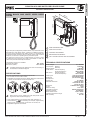
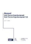
The Utopia video door phone is a colour device with an elegant,
revolutionary style and a particularly slim profile designed by Studio
De Lucchi.
The most outstanding feature of this video door phone is that it is a
free-hands model without handset.
Communication is established by pressing the button
and closed
when the button is released.
Utopia free-hands was designed to be installed in two different ways:
wall-mounted without the need for masonry work, or flush-mounted to
reduce the protrusion from the wall to only 16mm.
Utopia has two sets of auxiliary buttons in addition to colour, brightness
and contrast.
Three indicator LEDs are provided for more simple and immediate use.
These indicate open door, mute function and audio on conditions.
The video door phone can be used in all coax video door phone
systems using the specific brackets.
The vide door phone is available in the following versions:
• grey colour
Ref. 1703/2
• white colour
Ref. 1703/37
SPECIFICATIONS
APARTMENT VIDEO DOOR PHONE STATIONS
49 mm
142 mm
225 mm
UTOPIA FREE-HANDS COLOUR VIDEO DOOR PHONE
UTOPIA FREE-HANDS COLOUR VIDEO DOOR
PHONE
The main features of the video door phone are:
• Flat 4” TFT backlit colour module.
• Call speaker separate from conversation speaker.
• Adjustable call volume: when the call volume selector is in “MUTE”
( ) position, the corresponding LED lights up to indicate that the
call tone has been inhibited. The LED is visible also when the front
panel is closed (an additional wire is needed in the column for this
function).
• Adjustable colour and brightness of the picture by means of a
slider.
• Adjustable contrast by means of a trimmer positioned under the
sliding front panel.
• Two additional buttons ( , ) for activating, for example, secondary
door locks, staircase lights, switching the monitor on, etc.
• Door opener button: simply press the button to operate the door lock
(
); the button will remain lit as long as the picture appears on
the video door phone.
• Audio button: the green light in the button will stay as long as the
display is on; when the button is pressed, the green indicator LED
will light up and audio conversation is established.
• Open door indicator: a red LED lights up when the door is open if the
system is set up for this function (sensor installed).
• Video standard automatic selection according to the input signal
frequency.
−−−− sec.3b
2
3
6
5
4
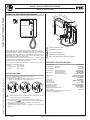
1) Audio button
2) Auxiliary buttons
3) Brightness adjustment control
4) Colour adjustment control
5) Contrast adjustment control
6) Call volume control
7) Open door button
8) Green audio on LED
9) Green mute LED
10) Red door open LED
TECHNICAL FEATURES
Power voltage: Consumption: Working: Stand-by:
Working power: CCIR Version Vertical frequency: Horizontal frequency: EIA Version Vertical frequency: Horizontal frequency: Video signal: LCD: Screen size: Resolution: Colour system: Switch-on delay: Transmitting capsule: Receiving capsule: Button break current ( , ): Operating temperature range: Max. humidity: 16 ÷ 18,5Vdc
0,36A max
0A
max 6,5W
50Hz ± 2Hz
15625 ± 300Hz
60Hz ± 2Hz
15734 ± 300Hz
1Vpp 75Ω nominal
1Vpp -6dB minimum
4” backlit
81 x 59mm
480H x 234V pixel
PAL
4 sec. max
electret microphone
speaker 45Ω
0,5A @ 30Vdc
-5° ÷ +45°C
90% UR
DOOR PHONE AND VIDEO DOOR PHONE SYSTEM: Product Technical Manual
UTOPIA FREE-HANDS COLOUR VIDEO DOOR PHONE
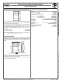
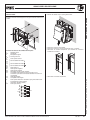
BRACKET Ref. 1703/91
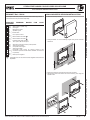
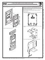
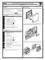
WALL-MOUNTED VERSION INSTALLATION
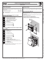
The Utopia video door phone is provided without fastening bracket.
The bracket must be purchased separately:
• Remove bracket protection.
BRACKET
SYSTEMS
TERMINAL
BOARD
FOR
COAX
R3 Silent video on (video only)
CA Call signal
2 Microphone signal
1 Speaker signal
6
10 Power earth
9 Door opener control
X2 X1 Service button terminals
Y2 Service button terminals
Y1
+ Indicator LED power positive
AP ‘Door open’ LED control input
RD Secondary video door phone power positive
R2 Video power positive
V3 Composite video signal
V5 Video signal earth
Composite video signal for second monitor in-out
connection (connect a 75Ω resistor between V4 and V5 if
V4
not present)
R1 R1 Video power negative
}
• Arrange bracket on wall considering height from ground and side
clearance.
m
6c
{
}
10
cm
155 cm
}
}
Terminals 6 and 10 are short-circuited together and cannot be
separated.
m
7c
UTOPIA FREE-HANDS COLOUR VIDEO DOOR PHONE
BRACKET
WALL-MOUNTED VERSION INSTALLATION
m
8c
APARTMENT VIDEO DOOR PHONE STATIONS
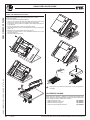
• Fasten the bracket to the wall using the bolts provided.
• Alternatively fasten the bracket to a flush-mounting box using the
specific holes.
DOOR PHONE AND VIDEO DOOR PHONE SYSTEM: Product Technical Manual
sec.3b −−−− UTOPIA FREE-HANDS COLOUR VIDEO DOOR PHONE
WALL-MOUNTED VERSION INSTALLATION
UTOPIA FREE-HANDS COLOUR VIDEO DOOR PHONE
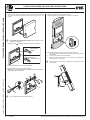
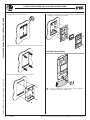
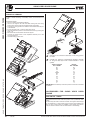
• Arrange wiring and refit the clip-on cover on the bracket. Remove
the cover only before fitting the Utopia video door phone on the
bracket.
• Remove the lower sliding protective covers.
• Check the position of the switches, as shown in the figure:
To exclude the ‘free-hands’ function: move jumper J1 from
position 2 to position 1.
Hold the button
pressed to establish the audio connection.
1
1
2
FREE HANDS
(default)
2
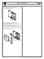
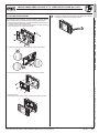
• Fit the Utopia video door phone on the bracket as follows:
1. Fasten the video door phone to the hooks B on the upper side of
the bracket.
2. Turn the video door phone downwards.
3. Shut the video door phone on the bracket and ensure that
fastening lever C is blocked.
1
AUDIO WITH
BUTTON PRESSED
2
Press lever C and reverse the sequence to remove the video
door phone.
• Remove the protective cover from the bracket.
• Remove the film (A) protecting the terminals.
IMPORTANT: THE VIDEO DOOR PHONE WILL NOT WORK IF
THE FILM IS NOT REMOVED.
B
A
B
APARTMENT VIDEO DOOR PHONE STATIONS
B
C
Do not change the trimmer default setting.
−−−− sec.3b
DOOR PHONE AND VIDEO DOOR PHONE SYSTEM: Product Technical Manual
UTOPIA FREE-HANDS COLOUR VIDEO DOOR PHONE
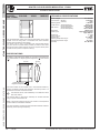
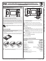
FLUSH-MOUNTED VERSION INSTALLATION
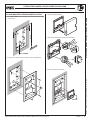
FLUSH-MOUNTED VERSION INSTALLATION
• Remove bracket protection.
UTOPIA FREE-HANDS COLOUR VIDEO DOOR PHONE
• Fit the Ref.1703/60 flush-mounting box at the recommended height
from the floor.
m
2c
P
TO
m
165 cm
2c
• Remove the three fastening teeth from the bracket.
Ref. 1703/60
• Fit the frame inside the box and adjust correct perpendicularity.
• Fasten the bracket to the frame.
P
TO
P
TO
C
D
DOOR PHONE AND VIDEO DOOR PHONE SYSTEM: Product Technical Manual
sec.3b −−−− APARTMENT VIDEO DOOR PHONE STATIONS
P
TO
UTOPIA FREE-HANDS COLOUR VIDEO DOOR PHONE
FLUSH-MOUNTED VERSION INSTALLATION
UTOPIA FREE-HANDS COLOUR VIDEO DOOR PHONE
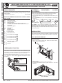
• Arrange wiring.
• Remove the sliding protective covers.
• Check the position of the switches, as shown in the figure:
P
TO
To exclude the ‘free-hands’ function: move jumper J1 from
position 2 to position 1.
Hold the button
pressed to establish the audio connection.
1
APARTMENT VIDEO DOOR PHONE STATIONS
1
2
2
2
FREE HANDS
(default)
Before you put the video door phone Ref. 1703/37 on the
bracket remove the lateral cover as shown below.
1
AUDIO WITH
BUTTON PRESSED
• Remove the film (A) protecting the terminals.
IMPORTANT: THE MONITOR WILL NOT WORK IF THE FILM IS
NOT REMOVED.
A
Do not change the trimmer default setting.
−−−− sec.3b
DOOR PHONE AND VIDEO DOOR PHONE SYSTEM: Product Technical Manual
UTOPIA FREE-HANDS COLOUR VIDEO DOOR PHONE
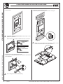
INSTALLATION ON PLASTERBOARD WALLS
Proceed as follows:
• Drill box Ref. 1703/60 with a Ø 2.2mm bit to form the through holes
shown in the figure below.
P
TO
Sch. 1703/60
Sett/fab. 25.01.2006
E
• Fasten the adapter brackets of the box with the 3.5 x 9.5mm
screws.
• Refit the sliding protective covers.
243 mm
• Break into the plasterboard wall as shown the drawing below.
m
0m
165 cm
16
DOOR PHONE AND VIDEO DOOR PHONE SYSTEM: Product Technical Manual
sec.3b −−−− APARTMENT VIDEO DOOR PHONE STATIONS
The specific 1703/61 kit is required to install Utopia free-hands video
door phone on plasterboard walls.
The kit consists of a set of backing fasteners for 12 mm and 24 mm
thick walls, adapted brackets and screws needed for installation.
UTOPIA FREE-HANDS COLOUR VIDEO DOOR PHONE
INSTALLATION ON PLASTERBOARD WALLS
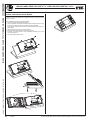
• Fasten the video door phone to the frame.
UTOPIA FREE-HANDS COLOUR VIDEO DOOR PHONE
Volume adjustment
UTOPIA FREE-HANDS COLOUR VIDEO DOOR PHONE
• Fit the backing fasteners in the hole.
•Follow the instructions shown in the paragraph “Flush-mounting
installation” to complete the installation.
0
06
03/6 1.20
. 17 25.0
Sch ab.
t/f
Set
P
TO
• Drill the wall at the holes on the backing fasteners with a Ø 2.2mm
bit.
Volume adjustment
APARTMENT VIDEO DOOR PHONE STATIONS
• Fix the box to the wall using 2.9 x 32mm screws.
0
06
03/6 1.20
. 17 25.0
Sch ab.
t/f
Set
−−−− sec.3b
Volume is calibrated to optimal values during production.
Change the settings when needed only.
DOOR PHONE AND VIDEO DOOR PHONE SYSTEM: Product Technical Manual
UTOPIA FREE-HANDS COLOUR VIDEO DOOR PHONE
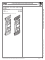
ACCESSORIES FOR UTOPIA VIDEO DOOR PHONES
UTOPIA FREE-HANDS COLOUR VIDEO DOOR PHONE
ACCESSORIES FOR UTOPIA VIDEO DOOR
PHONES
The video door phone can be customised by replacing the front flaps
with the following models:
• Yellow
Ref. 1703/51
• Green
Ref. 1703/52
• Anthracite black
Ref. 1703/53
APARTMENT VIDEO DOOR PHONE STATIONS
Replace by removing the sliding protection flaps.
Refit the protective flaps.
DOOR PHONE AND VIDEO DOOR PHONE SYSTEM: Product Technical Manual
sec.3b −−−− UTOPIA COLOUR VIDEO DOOR PHONE Ref. 1703/17
SPECIFICATIONS
TECHNICAL FEAUTURES
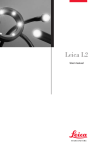
180 mm
8
7
6
1
2
The Utopia video door phone is a colour device with an elegant,
revolutionary style and a particularly slim profile (protruding only 55
millimetres from the wall) designed by Studio De Lucchi.
Some settings are arranged under the front sliding cover to make the
design more streamline and convenient.
Standard controls of Utopia, in addition to colour, brightness and
contrast, include three auxiliary buttons, door open LED and mute on
LED.
The video door phone is easy to install because no masonry work is
needed and all connections are made to the bracket on which the video
door phone will eventually be fastened. The video door phone can be
used both in coax or 5-wire systems using the specific brackets. The
handset is connected simply by means of a telephone plug.
The video door phone Ref. 1703/17 is set up to a speaker capable
interfacing with hearing aids by means of the “T” function.
SPECIFICATIONS
APARTMENT VIDEO DOOR PHONE STATIONS
55 mm
225 mm
UTOPIA COLOUR VIDEO DOOR PHONE
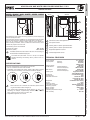
UTOPIA COLOUR VIDEO DOOR PHONE
Ref. 1703/17
The main features of the video door phone are:
• Flat 4” TFT backlit colour module
• Call speaker separate from handset
• Adjustable call volume: when the call volume selector is in “MUTE”
( ) position, the corresponding LED lights up to indicate that the
call tone has been inhibited. The LED is visible also when the front
panel is closed (an additional wire is needed in the column for this
function).
• Adjustable colour and brightness of the picture by means of a
slider.
• Adjustable contrast by means of a trimmer positioned under the
sliding front panel.
• Three additional buttons ( ,
and ) for activating, for example,
secondary door locks, staircase lights, switching the monitor on,
etc.
• Door opener button: simply press the button to operate the door lock
(
); the button will remain lit as long as the picture appears on
the video door phone.
• Open door indicator: a red LED lights up when the door is open if the
system is set up for this function.
• Video standard automatic selection according to the input signal
frequency.
10 −−−− sec.3b
5
3
4
1) 2) 3) 4) 5) 6) 7) 8) Auxiliary buttons
Contrast adjustment trimmer
Brightness adjustment trimmer
Colour adjustment trimmer
Call tone adjustment trimmer
Door opener button
Mute function led
Open door led
TECHNICAL FEAUTURES
Power voltage: Consumption: Working: Stand-by: Working power: CCIR Version Vertical frequency: Horizontal frequency:
EIA Version Vertical frequency: Horizontal frequency: Video signal: LCD: Screen size: Resolution: Colour system:
Switch-on delay: Transmitting capsule: Receiving capsule: Button break current ( , ): (Electronic call to max. 2 loudspeaker)
Operating temperature range: Max. humidity: 16 ÷ 18,5Vdc
0,36A max
0A
6,5W max
50Hz ± 2Hz
15625 ± 300Hz
60Hz ± 2Hz
15734 ± 300Hz
1Vpp 75Ω nominal
1Vpp -6dB minimum
4” backlit
81 x 59mm
380H x 250V pixel
PAL
4 sec. max
electret microphone
speaker 45Ω
0,5A @ 30Vdc
-5° ÷ +50°C
90% UR
DOOR PHONE AND VIDEO DOOR PHONE SYSTEM: Product Technical Manual
UTOPIA FREE-HANDS COLOUR VIDEO DOOR PHONE
BRACKET
INSTALLATION
The Utopia video door phone is provided without fastening bracket.
The bracket must be purchased separately according to the type of
system being installed:
• Bracket for 5-wire system
Ref. 1703/955
• Bracket for coax system
Ref. 1703/90
INSTALLATION
• Remove bracket protection.
The derivation of video door phone can not be in/out.
BRACKET TERMINAL BOARD FOR 5-WIRE SYSTEMS
Ref. 1703/955
}
}
Y1 Y2 Service button terminals
X2 X1 Service button terminals
CA1 Floor call signal
2 Voice for door phone intercom
CA Call signal
G Monitor silence auto-on (video only)
B Differential video signal positive
A Differential video signal negative
Z1 Z2 Service button terminals
AP ‘Door open’ LED control input
+ Indicator LED power positive
R1 Video door phone power negative
R1
R2 Video door phone power positive
RD Secondary video door phone power positive
}
• Arrange the conduit so that it ends in correspondence with the wire
opening of the bracket, considering the height from the floor and the
side clearance requirements shown in the figure.
UTOPIA COLOUR VIDEO DOOR PHONE
BRACKET
}
m
R3 Silent video on (video only)
CA Call signal
2 Microphone signal
1 Speaker signal
6
10 Power earth
9 Door opener control
X2 X1 Service button terminals
Y2 Y1 Service button terminals
Z1 Z2 Service button terminals
+ Indicator LED power positive
AP ‘Door open’ LED control input
RD Secondary video door phone power positive
R2 Video power positive
V3 Composite video signal
V5 Video signal earth
Composite video signal for second monitor in-out
connection (connect a 75Ω resistor between V4 and V5 if
V4
not present)
R1 Video power negative
R1
10
}
m
7c
}
}
}
10
cm
cm
• Fasten the bracket to the wall using the screws and bolts provided
or alternatively using a flush mounting box 503 and specific holes.
{
Mod. 503
}
Cut the P1 jumper to use this bracket in intercom systems. In
intercom system the diode is not necessary.
DOOR PHONE AND VIDEO DOOR PHONE SYSTEM: Product Technical Manual
sec.3b −−−− 11
APARTMENT VIDEO DOOR PHONE STATIONS
BRACKET TERMINAL BOARD FOR COAX SYSTEMS
Ref. 1703/90
155 cm
6c
UTOPIA COLOUR VIDEO DOOR PHONE
ACCESSORIES FOR UTOPIA VIDEO DOOR PHONES
ACCESSORIES FOR UTOPIA VIDEO DOOR
PHONES
UTOPIA COLOUR VIDEO DOOR PHONE
• Arrange wiring.
The video door phone can be customised by replacing the front flaps
with the following models:
• Yellow
Ref. 1703/51
• Green
Ref. 1703/52
• Anthracite black
Ref. 1703/53
Replace by removing the sliding protection flaps.
It is advisable to refit the protective cover if the video door
phone is not immediately installed on the bracket.
• Remove the film (A) protecting the terminals.
B
B
A
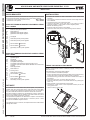
• Fasten the monitor to the hooks B on the upper side of the bracket
and turn the monitor downwards.
• Shut the monitor on the bracket and ensure that fastening lever C is
blocked.
APARTMENT VIDEO DOOR PHONE STATIONS
Refit the protective flaps.
B
C
• Press lever C and reverse the sequence to remove the monitor.
12 −−−− sec.3b
DOOR PHONE AND VIDEO DOOR PHONE SYSTEM: Product Technical Manual
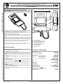
SCAITEL BLACK AND WHITE VIDEO MODULE
SPECIFICATIONS
TECHNICAL SPECIFICATIONS
Mod. 1732 video module is a monitor whose most important
characteristic is that of being used in combination with other Scaitel
devices which present the same design.
The device can be used in combination with other Scaitel devices
(e.g. door phone or picture memory module) to create a basic video
door phone (video module with door phone) or complex device (video
module with door phone and picture memory).
The video module implements both CCIR and EIA transmission
standards:
• CCIR version (50Hz) Ref. 1732/1
• EIA version (60Hz) Ref. 1732/18
TECHNICAL SPECIFICATIONS
Power: 16 ÷ 18.5Vdc
Consumption: Working:
0.35A max
Stand-by:
0mA
Working power: 6.5W max
CCIR version: Vertical frequency: 50Hz ± 2Hz
Horizontal frequency: 15625 ± 400Hz
EIA version: Vertical frequency: 60Hz ± 2Hz
Horizontal frequency: 15734 ± 400Hz
Resolution: 400 lines in middle of screen
Video input: 1Vpp-75Ohm nominal 1Vpp -6dB min
Kinescope: 4” flat
Phosphorous: P45
Screen size:
81 x 59mm
Geometric distortion:
vertical 8% max - horizontal 12% max
Brightness: 170cd/m2 max. setting
Working temperature range:
- 5 + 45°C
Storage temperature range: -20 + 60°C
Humidity: 90% RH max
Note: suitable cameras must be fitted in the door unit according to
the transmission standard of the monitor.
SCAITEL BLACK AND WHITE VIDEO MODULE
SCAITEL BLACK AND WHITE VIDEO MODULE
SPECIFICATIONS
220 mm
Available in matte white plastic (ABS) only, the device is equipped with
two potentiometers for adjusting picture brightness ( ) and contrast
( ).
167 mm
56 mm
Brightness adjustment
APARTMENT VIDEO DOOR PHONE STATIONS
Contrast adjustment
The video module can be installed next to other Scaitel modules by
means of brackets provided and fastened to the wall by means of a
bracket with connector and terminal board.
The monitor (basic or with add-on modules) can be table-mounted
using a specific transformation kit.
DOOR PHONE AND VIDEO DOOR PHONE SYSTEM: Product Technical Manual
sec.3b −−−− 13
Ref. 1732/41
SCAITEL COLOUR VIDEO MODULE Ref. 1732/41
SPECIFICATIONS
TECHNICAL SPECIFICATIONS
ATLANTICO COLOUR VIDEO DOOR PHONE
SCAITEL
COLOUR
Ref. 1732/41
VIDEO
MODULE
Like the black/white module, the most important feature of this video
module is that of being used in combination with other SCAITEL
devices which present the same design.
The device can be used in combination with other Scaitel devices
(e.g. door phone or picture memory module) to create a basic video
door phone (video module with door phone) or complex device (video
module with door phone and picture memory).
TECHNICAL SPECIFICATIONS
Power voltage: 16 ÷ 18.5Vdc
Consumption: Working:
0.35A max
Stand-by: 0mA
Working power: 6.5W max
CCIR version: Vertical frequency: 50Hz ± 2Hz
Horizontal frequency: 15625 ± 400Hz
EIA version: Vertical frequency: 60Hz ± 2Hz
Horizontal frequency: 15734 ± 400Hz
Resolution: 480H x 234V
Video signal: 1Vpp-75Ohm nominal
1Vpp -6dB min
Kinescope: 4” TFT
Colour system: PAL
Screen size: 81 x 59mm
Working temperature range: - 5 + 45°C
Storage temperature range: -20 + 60°C
Humidity: 90% RH max
SPECIFICATIONS
Available in matte white plastic (ABS) only, the device is equipped with
two potentiometers for adjusting picture brightness ( ) and contrast
( ).
56 mm
220 mm
167 mm
APARTMENT VIDEO DOOR PHONE STATIONS
Colour adjustment
Brightness adjustment
The video module can be installed next to other Scaitel modules by
means of brackets provided and fastened to the wall by means of a
bracket with connector and terminal board.
The brackets can be used indifferently on all black and white
and colour videos.
The monitor (basic or with add-on modules) can be table-mounted
using a specific transformation kit.
Refer to the “Indoor video door phone units” section for the respective
product sheets and installation methods.
The video module is provided with video standard automatic selection
according to the input signal frequency.
14 −−−− sec.3b
DOOR PHONE AND VIDEO DOOR PHONE SYSTEM: Product Technical Manual
SCAITEL VIDEO MODULE
VIDEO DOOR PHONE BRACKET
INSTALLATION
VIDEO MODULE BRACKET
WALL-MOUNTED VERSION
Proceed as follows to fasten the video module only:
• Arrange the duct so that it ends in correspondence with the input
hole.
• Fasten the bracket to the wall at the height from the floor shown by
means of bolts.
• Connect the wires to the specific terminals.
• Extract the stop bolt A.
• Fasten the monitor to the bracket and lock the device by pushing the
bolt “A” inwards.
Ref. 1732/91
1732/955
Video
module
1,55 m
The bracket for installing the video module must be purchased
separately.
There are two types of brackets according to the system where they
will be installed:
• Bracket for coax systems Ref. 1732/91
• Bracket for 5-wire systems Ref. 1732/955
BRACKET TERMINAL BOARD FOR 5-WIRE SYSTEMS
Ref. 1732/955
Earth for door phone (*)
Voice for door phone (*)
Call signal
-Differential video signal positive
Differential video signal negative
Video door phone power negative
Video door phone power positive
Secondary monitor power positive
Silent video on
(*) To install the video door phone in 5-wire systems, connect the
Ref. 1132/35 door phone to these terminals.
BRACKET TERMINAL BOARD FOR COAX SYSTEMS
Ref. 1732/91
CA
R3
R1
R2
V4
Call signal
Silent video on
Video power negative
Video power positive
Composite video signal for second monitor in-out
connection (connect a 75Ω resistor between V4 and V5 if
not present)
V5 Video signal earth
V3 Composite video signal
RD Secondary monitor power positive
INSTALLATION
The video module, as shown, can be used separately or in combination
with Scaitel door phone model or 1332 door telephone model.
The door telephone can either be installed separately or in combination
with telephone interface and PABX 1/5 and 2/8 switchboards.
In all configurations, the video module must be arranged on the left and
the door telephone on the right (the telephone interface and the PABX
telephone switchboards, where relevant, must also be positioned
immediately to the left of the door telephone).
Refer to “Telefony technical manual” for details.
VIDEO DOOR PHONE (VIDEO + DOOR PHONE MODULE)
Two installation arrangements are possible:
with or without flush-mounting box. In any case, plate kit Ref. 1032/59
will be needed to join the devices.
INSTALLATION WITH FLUSH-MOUNTING BOX
Proceed as follows:
• Install the box in line with the wall at a height of 1.40 m from the floor
considering that the monitor will be arranged approximately 10 cm
to the left of the flush-mounting box.
• Lead all the wires out of the flush-mounting box and prepare to
direct them to the respective connections of the monitor and the
door phone through the corresponding holes in the bracket and the
door phone base.
The box dimension are indicative.
1,40 m
13
0m
m
31
mm
• Fit the two L-brackets for fitting the base of the door phone before
fastening the monitor bracket to the wall.
Fasten the monitor bracket so that the upper part of the wire input is
in line with the inner wall of the box and the left part is 12mm away.
DOOR PHONE AND VIDEO DOOR PHONE SYSTEM: Product Technical Manual
12 mm
sec.3b −−−− 15
APARTMENT VIDEO DOOR PHONE STATIONS
1
2
CA
R5
B
A
R1
R2
RD
R3
A
70 mm
SCAITEL VIDEO MODULE
VIDEO MODULE
SCAITEL VIDEO MODULE
SCAITEL VIDEO MODULE
INSTALLATION
• Fasten the bracket by means of the bolts, position the door phone
base on the two tabs and fasten to the wall.
• Connect the wires to the specific terminals and then fasten the video
module and the door phone top.
APARTMENT VIDEO DOOR PHONE STATIONS
INSTALLATION WITHOUT FLUSH-MOUNTING BOX
Fit the two L-brackets for fitting the base of the door phone before
fastening the monitor bracket to the wall.
• Fasten the bracket by means of the bolts, position the door phone
base on the two tabs and fasten to the wall.
• Arrange the wire output in correspondence with the output hole.
• Follow the indications in the figure for interconnections between
video module and door phone after cutting the areas in the top
sides.
• Connect the wires to the specific terminals and then fasten the video
module and the door phone top.
16 −−−− sec.3b
DOOR PHONE AND VIDEO DOOR PHONE SYSTEM: Product Technical Manual
Sch. 1740/1
SIGNO BLACK AND WHITE VIDEO DOOR PHONE
SPECIFICATIONS
TECHNICAL SPECIFICATIONS
50
20
mm
5m
m
225 mm
1
5
2
3
4
The following versions are available:
CCIR version (50Hz): EIA version (60Hz): Ref. 1740/1
Ref. 1740/18
A suitable camera must be fitted in the door unit according to
the trasmission standard employed.
SPECIFICATIONS
The main characteristics of the video door phone are:
• Flat 4” black and white video module.
• Adjustable and mutable call volume. (Mute). When the mute function
is active, the red indicator on the front panel is on.
MAX.
MIN.
MUTE
When volume is set to “MUTE” the video door phone will not
ring but the video module will light up.
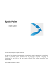
3 Contrast adjustment
4 Brightness adjustment
5 Call volume control and adjustment
TECHNICAL SPECIFICATIONS
Power voltage: Consumption: Working: Stand-by: Working power: CCIR version Vertical frequency: Horizontal frequency: EIA version Vertical frequency: Horizontal frequency: Video signal: Kinescope: Phosphorous: Screen size: Geometric distorsion: Brightness: X-rays: Switch-on delay: Transmitting capsule: Receiving capsule: Button break current: Operating temperature range: Max. humidity: 16 ÷ 18,5Vdc
0,35A max
0A
6,5W max
50Hz ± 2Hz
15625 ± 300Hz
60Hz ± 2Hz
15734 ± 300Hz
1Vpp 75 Ω nominal
1Vpp -6dB minimum
4,5” flat 13mm neck
P45
81 x 59mm
vertical 5% max
horizontal 5% max
barrel 10% max
170cd/m2 max. setting
none
7 sec. max
electret microphone
45 Ω speaker
0,5A @ 18Vdc
-5° ÷ +50°C
90% RH
• Door opener button is lit up and blue when video module is on.
• Service buttons ( , ,
) for activating, for example, supplementary
electrical locks, staircase lights, monitor auto-on function, etc.
• Adjustable brightness and contrast.
DOOR PHONE AND VIDEO DOOR PHONE SYSTEM: Product Technical Manual
sec.3b −−−− 17
APARTMENT VIDEO DOOR PHONE STATIONS
Signo door phone, designed by architect Citterio, is provided with 1 blue
led backlit door lock release button, 3 buttons for additional services,
ring tone volume adjustment with “Mute” function. It is equipped with
a special handset, that allows hard of hearing people, with a special
earphone, to hear who is speaking at the push button panel.
The video door phone is easy to install because no masonry work
is needed and all connections are made to the bracket on which the
video door phone will eventually be fastened.
1 Door opener button
2 Auxiliary buttons
SIGNO BLACK AND WHITE VIDEO DOOR PHONE
SIGNO BLACK AND WHITE VIDEO DOOR
PHONE
SIGNO COLOUR VIDEO DOOR PHONE
SPECIFICATIONS
TECHNICAL SPECIFICATIONS
SIGNO COLOUR VIDEO DOOR PHONE
SIGNO COLOUR VIDEO DOOR PHONE
50
20
mm
5m
m
225 mm
1
5
2
3
4
1 Door opener button
Signo video door phone, designed by architect Citterio, is a colour or
black/white apartment station equipped with 1 blue led backlit door
lock release button, 3 buttons for additional services, ring tone volume
adjustment with “Mute” function. It is equipped with a special handset,
that allows hard of hearing people, with a special earphone, to hear
who is speaking at the push button panel.
The video door phone is easy to install because no masonry work
is needed and all connections are made to the bracket on which the
video door phone will eventually be fastened.
For a greater compatibility with furniture, the video door phone is
available in the following colours:
• White Ref. 1740/40
• Anthracite grey Ref. 1740/41
• Platinum Ref. 1740/42
APARTMENT VIDEO DOOR PHONE STATIONS
SPECIFICATIONS
The main characteristics of the video door phone are:
• Flat 4” LCD colour module.
• Adjustable and mutable call volume (Mute). When the mute function
is active, the red indicator on the front panel is on.
MAX.
MIN.
MUTE
2 Auxiliary buttons
3 Colour adjustment
4 Brightness adjustment
5 Call volume control and adjustment
TECHNICAL SPECIFICATIONS
Power voltage: 16 ÷ 18,5Vdc
Consumption: Working: 0,35A max
Stand-by: 0A
Working power: 6,5W max
CCIR version Vertical frequency: 50Hz ± 2Hz
Horizontal frequency: 15625 ± 300Hz
EIA version Vertical frequency: 60Hz ± 2Hz
Horizontal frequency: 15734 ± 300Hz
Video signal: 1Vpp 75 Ω nominal
1Vpp -6dB minimum
LCD: 4” back-lit
Screen size: 81 x 59mm
Resolution: 380H x 250V pixel
Colour system: PAL
Switch-on delay: 4 sec. max
Transmitting capsule: electret microphone
Receiving capsule: 45 Ω speaker
Button break current: 0,5A @ 18Vdc
Operating temperature range: -5° ÷ +50°C
Max. humidity: 90% RH
Video standard automatic selection according
to the input signal frequency.
When volume is set to “MUTE” the video door phone will not
ring but the video module will light up.
• Door opener button is lit up and blue when video module is on.
• Service buttons ( , ,
) for activating, for example, supplementary
electrical locks, staircase lights, monitor auto-on function, etc.
• Adjustable brightness and colour.
• Video standard automatic selection according to the input signal
frequency.
18 −−−− sec.3b
DOOR PHONE AND VIDEO DOOR PHONE SYSTEM: Product Technical Manual
SIGNO COLOUR VIDEO DOOR PHONE
SIGNO BRACKETS
INSTALLATION
The Signo video door phone is provided without fastening bracket; the
bracket must be purchased separately according to the type of system
being installed:
• Bracket for 5-wire systems Ref. 1740/955
• Bracket for coax systems Ref. 1740/90
The device can be wall-mounted (on a bracket) or rested on a horizontal
surface by using the specifi c tabletop stand in addition to the bracket.
The bracket can be used either with colour and black and white
video door phone.
BRACKET TERMINAL BOARD FOR 5-WIRE
SYSTEMS Ref. 1740/955
A Differential video signal negative
R2 Video door phone power positive
RD Secondary monitor power positive
B Differential video signal positive
2 Voice for possible door phone intercom
G Monitor silence auto-on (video only)
R1 Video door phone power negative
CA Call signal
CA1 Floor call signal
X1 Service button terminals
X2
Y1
Service button terminals
Y2
Z1
Service button terminals
Z2
WALL-MOUNTED VERSION
The video door phone can be wall mounted (using the bracket)
following the steps below:
• Arrange the duct so that it ends in correspondence with one of the
input holes.
• Fasten the bracket to the wall at the height from the floor shown by
means of the four screws.
• Connect the wires to the specific terminals.
• Extract the retainer hook α pulling downwards.
• Fasten the monitor to the bracket as shown in the figure.
• Fasten the monitor by pushing the retainer hook α upwards.
1
}
}
}
SIGNO COLOUR VIDEO DOOR PHONE
SIGNO BRACKETS
INSTALLATION
Bracket terminal board for coax systems
Ref. 1740/90
1,55 m
1Speaker signal
CA Call signal
2 Microphone signal
6
Power ground
10
9 Door opener control
X1
Service button terminals
X2 Y1
Service button terminals
Y2 Z1
Service button terminals
Z2 R3 Silent video on
R1 Video power negative
R2 Video power positive
RD Secondary monitor power positive
Composite video signal for second monitor in-out
V4 connection (connect a 75Ω resistor between V4 and V5 if
not present)
V5 Video signal earth
V3 Composite video signal
}
}
}
}
If the coaxial cable is connected in in/out mode, connect the
terminal pins R1 and V5 on the bracket.
3
α
DOOR PHONE AND VIDEO DOOR PHONE SYSTEM: Product Technical Manual
sec.3b −−−− 19
APARTMENT VIDEO DOOR PHONE STATIONS
2
SIGNO VIDEO DOOR PHONE
ACCESSORIES FOR SIGNO VIDEO DOOR PHONE
APARTMENT VIDEO DOOR PHONE STATIONS
SIGNO VIDEO DOOR PHONE
TABLETOP VERSION
Signo video door phone can be table-mounted using the specifi c
kit Ref. 1740/92 containing: one tabletop stand, one socket and one
cord.
Proceed as follows:
• Fix the bracket to the table-top adaptor.
• Insert in the support rear hole the cable coming from the wiring
junction box and fix it with the provided jumper and screws.
• Connect the wiring junction box cables to the suitable terminal pins
of the bracket.
• Pull out the stop hook α from the video door phone.
• Insert the video door phone in the bracket and lock it by pushing the
hook α up.
• Mount the feet on the bottom side of the support.
• Connect the system wires to the respective terminal pins of the
wiring junction box.
• Close the wiring junction box.
Write down the connection references on the wiring junction
box label.
Consider the following correspondence between terminals
for using the table-top kit with 1740/92 brackets in 5-wire
systems
Table mountig kit
Ref. 1740/92
R1
R2
V3
V5
CA/RZ
R3
X1
X2
Y1
Y2
Z1
Z2
2
Bracket
Ref. 1740/955
R1
R2
A
B
CA
G
X1
X2
Y1
Y2
Z1
Z2
2
Important: Two table-top video door phones cannot be connected
in parallel
ACCESSORIES FOR SIGNO VIDEO DOOR
PHONE
ADD ON Ref. 1740/86
α
20 −−−− sec.3b
The additional module with bracket may be purchased separately
and combined to the basic video door phone unit in system with coax
cable.
A switch may be used to mute the call tone and a green LED will light
up to indicate this. A second LED may be used to check whether the
door is open (if this function is available in the system). Six buttons
may be used for intercom calls to other devices in the building.
DOOR PHONE AND VIDEO DOOR PHONE SYSTEM: Product Technical Manual
SIGNO VIDEO DOOR PHONE
ACCESSORIES FOR SIGNO VIDEO DOOR PHONE
INSTALLATION
• Extract the retainer hook α pulling downwards.
α
1,55 m
24
SIGNO VIDEO DOOR PHONE
Arrange the duct so that it ends near the input hole and fasten the
bracket to the wall at the height from the ground shown with the four
screws.
6m
m
Connect the wires to the suitable terminal pins.
1 Speaker signal
CA Call signal
2 Microphone signal
6
Power ground 10
10
9 Door opener control
X1 Service button terminals
X2 Y1 Service button terminals
Y2 Z1 Service button terminals
Z2 R3 Silent video on
R1 Video power negative
R2 Video power positive
RD Secondary monitor power positive
V4 Composite video signal for second monitor in-out connection (connect a 75Ω resistor between V4 and V5 if not present)
V5 Video signal earth
V3 Composite video signal
• Fasten the monitor to the bracket.
• Fasten the monitor by pushing the retainer hook α upwards.
• Rimuovere la mostrina trasparente per accedere al cartoncino
indicazione nominativi.
}
}
}
}
APARTMENT VIDEO DOOR PHONE STATIONS
• Rimontare la mostrina trasparente.
R Door opener direct from call button (only with switch at off and presence of relay 788/52)
+ LED power positive (12Vdc)
AP Door open control
T1
T2
T3
G/T
G/T2
T4
T5
T6
J3
DOOR PHONE AND VIDEO DOOR PHONE SYSTEM: Product Technical Manual
sec.3b −−−− 21
SIGNO VIDEO DOOR PHONE
ACCESSORY BOARD
Per l’installazione del videocitofono con l’aggiuntivo tasti ad appoggio
tavolo occorre acquistare l’apposito supporto Sch. 1740/93.
Proceed as follows:
• Fix the bracket to the table-top adaptor.
• Insert in the support rear hole the cable coming from the wiring
junction box and fix it with the provided jumper and screws.
• Connect the wiring junction box cables to the suitable terminal pins
of the bracket.
• Pull out the stop hook α from the video door phone.
• Insert the video door phone in the bracket and lock it by pushing the
hook α up.
• Mount the feet on the bottom side of the support.
• Connect the system wires to the respective terminal pins of the
wiring junction box.
• Close the wiring junction box.
APARTMENT VIDEO DOOR PHONE STATIONS
SIGNO VIDEO DOOR PHONE
TABLE TOP VERSION INSTALLATION
α
Write down the connection references on the wiring junction
box label.
ACCESSORY BOARD
Signo video door phones, in addition to the accessories listed in the
previous section, can be equipped with the following devices (described
in the “Apartment station accessories” section).
• Additional outdoor ringer Ref. 9854/40
• Additional electronic call ringer Ref. 9854/41
• Additional three-tone ringer Ref. 9854/42
• 12Vca door phone electronic buzzer Ref. 9854/52
22 −−−− sec.3b
DOOR PHONE AND VIDEO DOOR PHONE SYSTEM: Product Technical Manual
Ref. 1707/1
IMAGO HANDS-FREE COLOUR TFT 4” VIDEO DOOR PHONE Ref. 1707/1
SPECIFICATIONS
TECHNICAL SPECIFICATIONS
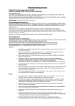
220 mm
1
124 mm
2
6
7
10
8
9
Imago video door phone has been designed by architect Trabucco and
it is provided with a dedicated call loudspeaker; the ring tone volume
can be adjusted on three levels (high-low-mute).
Imago is equipped with other 4 buttons, used for additional services, and
with an OSD display that allows to adjust display colour, brightness and
contrast using a joystick on the video door phone. During installation, it
is possible to select the operation mode: hands-free or button pressed.
In the first case, after receiving the call, the user must press the button
Audio On to start the conversation and press again the same button
to stop it. In the second case, the user must keep the button Audio On
pressed for all the conversation time.
The video door phone Ref. 1707/17 is set up to a speaker
capable interfacing with hearing aids by means of the “T”
function.
SPECIFICATIONS
The main characteristics of the video door phone are:
• Flat 4” TFT colour video module.
• Video standard automatic selection according to the input signal
frequency
• Call volume adjustment and Mute function. With “Mute” function
active (ring tone excluded), a red mechanical indicator appears.
3
4
5
1 AUXILIARY BUTTONS: these can be used for specifi c functions
according to the system.
2 JOYSTICK: this is used to adjust the video parameters.
3 The left joystick button is used to decrease video parameters.
4 The right joystick button is used to increase video parameters.
5 SELECT: This button is used to select the video parameter to be
adjusted.
6 AUTO-ON BUTTON
7 DOOR OPENER BUTTON: This turns green when the video
door phone is on. It turns red to indicate that the door is open
and blinks red to indicate that the automatic door opening
function is on.
8 AUDIO BUTTON: This turns green when the video door phone
is on. Press the button to activate the audio signal; the button
turns on in orange.
IMAGO HANDS-FREE COLOUR TFT 4” VIDEO DOOR PHONE
IMAGO HANDS-FREE COLOUR TFT 4” VIDEO
DOOR PHONE Ref. 1707/1
9 CALL VOLUME/MUTE CONTROL
10 MUTE INDICATOR
MAX.
MIN.
MUTE
When volume is set to “MUTE” the video door phone will not
ring but the video module will light up.
Power voltage: 16 ÷ 26Vdc
Consumption: 0,36A max
CCIR version Vertical frequency: 50Hz ± 2Hz
Horizontal frequency: 15625 ± 300Hz
EIA version Vertical frequency: 60Hz ± 2Hz
Horizontal frequency: 15734 ± 300Hz
Video signal: 1Vpp ± 10%
Kinescope: 4” TFT (with OSD)
Video impedance:
>10KW
Resolution: 960H x 234V dot
Receiving capsule: 45 Ω speaker
OSD menu:
Brigthness, colour and contrast
Call ring tone max. volume:
≥ 85 dB
Transmitting capsule: electret microphone
Button voltage: 24 V eff. max.
Button current: 0.5 A eff.
Operating temperature range: -5° ÷ +50°C
Max. humidity: 90% RH
Video standard automatic selection according
to the input signal frequency.
DOOR PHONE AND VIDEO DOOR PHONE SYSTEM: Product Technical Manual
sec.3b −−−− 23
APARTMENT VIDEO DOOR PHONE STATIONS
TECHNICAL SPECIFICATIONS
Ref. 1707/1
IMAGO HANDS-FREE COLOUR TFT 4” VIDEO DOOR PHONE Ref. 1707/1
IMAGO BRACKETS - ‘FREE-HANDS’ FUNCTION
CONTRAST, BRIGHTNESS, COLOUR ADJUSTMENT - INSTALLATION
IMAGO HANDS-FREE COLOUR TFT 4” VIDEO DOOR PHONE
IMAGO BRACKETS
The Imago video door phone is provided without fastening bracket; the
bracket must be purchased separately according to the type of system
being installed:
• Bracket for coax systems Ref. 1707/90
BRACKET TERMINAL BOARD FOR COAX SYSTEMS
Ref. 1707/90
RD Secondary monitor power positive
R2 Video power positive
V3 Composite video signal
V5 Video signal earth
V4 Composite video signal for second monitor in-out connection (connect a 75Ω resistor between V4 and V5 if not present)
R1 Video power negative
R3 Silent video on
CA Call signal
2 Microphone signal
1 Speaker signal
6
Power ground 10
10
9 Door opener control
X1 Service button terminals
X2 Y1 Service button terminals
Y2 Z1 Service button terminals
Z2 W1 Service button terminals
W2 + LED power positive (12Vdc)
AP Door open control
AI
Not used
AO
A-
CONTRAST,
ADJUSTMENT
BRIGHTNESS,
COLOUR
These video parameters can be adjusted only when the vide door
phone is on, after receiving a call or selecting the auto-on function.
• Use the joystick button (2) to access the setting menu.
• Press the right button (4) to increase and the left button (3) to
decrease.
• Press the SELECT (5) to go to the next parameter in the following
sequence:
contrast
brightness
exit
OSD menu
colour
reset
The RESET is used to return all parameters to the initial condition.
Press either the right or the left button of the joystick to reset the
parameters. Press the middle button to exit the setting menu.
The changes will not be stored if the video door phone goes out before
exiting setting mode.
}
INSTALLATION
}
}
}
}
The device can be wall-mounted (on a bracket) or rested on a horizontal
surface by using the specifi c tabletop stand in addition to the bracket.
WALL-MOUNTED VERSION
The video door phone can be wall mounted (with the bracket) following
the procedure below:
• Fix the wall mounting bracket with screws and screw anchors,
respecting the lateral dimensions.
}
10
cm
‘FREE-HANDS’ FUNCTION
To exclude the ‘free-hands’ function: move jumper J4 from position
1-2 to position 2-3. Hold the button
pressed to establish the audio
connection.
12
12
3
3
10
cm
1,55 m
APARTMENT VIDEO DOOR PHONE STATIONS
Press the audio button after receiving the call to establish the audio
conversation. You do not need to hold the button pressed during the
conversation. The audio conversation is cut off when either the button
is pressed again or when the video door phone is switched off.
1-2
FREEHANDS
(default)
• Perform wirings.
• Hang the video door phone, as shown in the figure.
• To replace the video door phone, press the hook α and rotate
clockwise.
2-3
AUDIO WITH
BUTTON PRESSED
α
24 −−−− sec.3b
DOOR PHONE AND VIDEO DOOR PHONE SYSTEM: Product Technical Manual
Ref. 1707/1
IMAGO HANDS-FREE COLOUR TFT 4” VIDEO DOOR PHONE Ref. 1707/1
INSTALLATION
Imago video door phone can be flush mounted, reducing the projection
from the wall to few millimetres. For this installation, buy the suitable
flush mounting box Ref. 1707/60 and follow the procedure below:
• Install the flush mounting box, respecting the lateral dimensions, at
a height of about 1,55m from the floor.
• After the wall has been painted, fix the frame to the flush mounting
box, using the 4 2,9 x 13 mm fixing screws.
10
In order to remove the monitor from the frame, put a slotted
screwdriver under the frame edge and lever it.
IMAGO HANDS-FREE COLOUR TFT 4” VIDEO DOOR PHONE
FLUSH MOUNTING MODEL
cm
• Cut the three fixing points of the bracket using the side cutters.
APARTMENT VIDEO DOOR PHONE STATIONS
• Fix the bracket to the frame using the 4 2,9 x 10 mm screws.
• Perform wirings.
• Mount the monitor, inserting it into the flush mounting box frame.
DOOR PHONE AND VIDEO DOOR PHONE SYSTEM: Product Technical Manual
sec.3b −−−− 25
Ref. 1707/1
IMAGO HANDS-FREE COLOUR TFT 4” VIDEO DOOR PHONE Ref. 1707/1
INSTALLATION
Imago video door phone can be table-top installed by using the suitable
kit Ref. 1707/50, which contains: a table-top support, a wiring junction
box and a cord.
For installation, follow the procedure below:
• Fix the bracket to the table-top adaptor.
• Insert in the rear hole of the support the cable coming from the wiring
junction box and fix it with the provided jumper and screw.
• Connect the wiring junction box wires to the suitable terminal pins of
the bracket
• Insert the video door phone on the bracket.
• Mount the feet on the bottom side of the support.
• Connect the system wires to the respective terminal pins of the
wiring junction box.
• Close the wiring junction box.
APARTMENT VIDEO DOOR PHONE STATIONS
IMAGO HANDS-FREE COLOUR TFT 4” VIDEO DOOR PHONE
TABLE-TOP INSTALLATION MODEL
26 −−−− sec.3b
DOOR PHONE AND VIDEO DOOR PHONE SYSTEM: Product Technical Manual
Ref. 1715/1
ARCO BLACK AND WHITE VIDEO DOOR PHONE Ref. 1715/1
SPECIFICATIONS
TECNICAL FEATURES
206 mm
230 mm
1
2
3
4
Arco offers the most modern technology applied to picture display and
the best quality/price ratio.
This video door phone is suitable for any new architectural environment
and can also be used to replace the old models Artico and Sentry+.
Arco can be surface mounted, without masonry work needed for
flush mounting installation, and is provided with a flat 4”screen, which
reduces its projection from the wall.
The following version are available:
CCIR version (50Hz) EIA version (60Hz) Ref. 1715/1
Ref. 1715/18
A suitable camera must be fi tted in the door unit according to
the transmission standard employed.
The video door phone Ref. 1715/17 is set up to a speaker
capable interfacing with hearing aids by means of the “T”
function.
SPECIFICATIONS
The main characteristics of the video door phone are:
• Flat 4” LCD black and withe video module
• Adjustable and mutable call volume. (Mute). With “Mute” function
active (ring tone excluded), a red mechanical indicator appears.
MAX.
MIN.
MUTE
When volume is set to “MUTE” the video door phone will not
ring but the video module will light up.
• Door opener button dedicated and service buttons (
and ) for
activating, for example, supplementary electrical locks, staircase
lights, video door phone auto-on function, etc.
• Adjustable brightness and contrast.
5
6
1 Call volume control and adjustment
2 Door opener button
3 Auxiliary button: used for special functions
4 Auxiliary button: used for special functions
5 Brightness adjustment control
6 Contrast adjustment control
ARCO BLACK AND WHITE VIDEO DOOR PHONE
70 mm
TECNICAL FEATURES
Power voltage: 16 ÷ 18,5Vdc
Consumption: Working: 0,6A max
Stand-by: 0A (coax)
5mA (5 wire)
Working power: 10W max
CCIR Version Vertical frequency: 50Hz ± 2Hz
Horizontal frequency: 15625 ± 300Hz
EIA version Vertical frequency: 60Hz ± 2Hz
Horizontal frequency: 15734 ± 300Hz
Video signal: 1Vpp 75Ω nominal
1Vpp -6dB minimum
Kinescope: 4” FLAT 20mm neck
Phosphorous: P45
Geometric distorsion: vertical 5% max
horizontal 5% max
barrel 10% max
Brightness: >100cd/m2 max. setting
X-rays: none
Switch-on delay: 7 sec. max
Transmitting capsule: electret microphone
Receiving capsule: speaker 45Ω
Button voltage: 24Veff. max
Button current: 1,2Aeff
Operating temperature range: -5° ÷ +50°C
Max. humidity: 90% UR
DOOR PHONE AND VIDEO DOOR PHONE SYSTEM: Product Technical Manual
sec.3b −−−− 27
APARTMENT VIDEO DOOR PHONE STATIONS
ARCO BLACK AND WHITE VIDEO DOOR
PHONE Ref. 1715/1
Ref. 1715/1
Arco BRACKETs - RETROFIT
INSTALLATION
Arco BRACKETs
INSTALLATION
Arco video door phone is provided without fastening bracket which must
be purchased separately according to the system being installed:
• Bracket for 5-wire systems (without coax) Ref. 1705/955
• Bracket for coax systems Ref. 1705/90
• Prepare the conduit so that it terminates at the infeed hole
provided.
• Use 4 plugs to fasten the bracket to the wall at the height from the
floor indicated.
• Connect the wires to the specific terminals.
• Check that the switch on the rear side is in A position if used in
analogue systems or in B position if used in digital systems.
• Extract the fastening hook α.
• Insert the video door phone in the bracket.
• Fasten the video door phone in place pushing hook A inwards.
BRACKET TERMINAL BOARD FOR 5-WIRE SYSTEMS
Ref. 1705/955
2Voice for door phone intercom
1Earth for door phone intercom
R3Silent video on
B Differential video signal positive
A Differential video signal negative
R5 -CA Call signal
CA
R2Video door phone power positive
R1 Video door phone power negative
R1
Y2
Service button
terminals
Y1
X2
Service button
terminals
X1
RTSecondary monitor power positive
R4 --
}
B
Staffa
}
}
}
BRACKET TERMINAL BOARD FOR COAX SYSTEMS
Ref. 1705/90
2Microphone signal
1Speaker signal
CA Call signal
R2Video power positive
V3 Composite video signal
V4 Composite video signal for second monitor in-out connection (connect a 75Ω resistor between V4 and V5 if not present)
V5Video signal earth
R3Silent video on
6
Power ground
10
R1Video power negative
Y2
Service button
terminals
Y1
X2
Service button
terminals
X1
9 Door opener control
RTSecondary monitor power positive
}
}
}
APARTMENT VIDEO DOOR PHONE STATIONS
A
RETROFIT
In a coaxial and 5 wire video door phone system, it is possible to
replace video door phone Mod. Sentry+ with video door phones Mod.
Arco. To simplify this replacement and reduce its cost, it is possible to
buy the bracket alone without the electronic circuit Ref. 1705/100.
Also when needing to replace only the bracket of a Sentry+ video door
phone it is possible to buy the bracket of the Artico video door phone
and fi t it with plastic support Ref. 1704/102.
The replacement operations are described in chapter 1F “Instructions
for interchangeability of Urmet devices” of the Door phone – Video
door phone installation diagram manual.
α
1,55 m
ARCO BLACK AND WHITE VIDEO DOOR PHONE
ARCO BLACK AND WHITE VIDEO DOOR PHONE Ref. 1715/1
TABLE-TOP INSTALLATION MODEL
Arco video door phone can be table-top installed by using the suitable
kit Ref. 1707/50, which contains: a table-top support, a wiring junction
box and a cord.
For installation, follow the procedure below:
• Fix the bracket to the table-top adaptor.
• Insert in the rear hole of the support the cable coming from the wiring
junction box and fix it with the provided jumper and screws.
• Connect the wiring junction box wires to the suitable terminal pins of
the bracket.
• Pull out the stop hook α from the video door phone.
• Insert the video door phone in the bracket and lock it by pushing the
hook α up.
• Mount the feet on the bottom side of the support.
• Connect the system wires to the respective terminal pins of the
wiring junction box.
• Close the wiring junction box.
The videophone Arco, moreover, can replace the Arctico model without
change the bracket.
28 −−−− sec.3b
DOOR PHONE AND VIDEO DOOR PHONE SYSTEM: Product Technical Manual
Ref. 1715/1
ARCO BLACK AND WHITE VIDEO DOOR PHONE Ref. 1715/1
ACCESSORIES
Consider the following correspondence between terminals
for using the table-top kit with 1715/50 brackets in 5-wire
systems.
Table mountig kit
Ref. 1750/50
R1
R2
V3
V5
CA/RZ
R3
X1
X2
Y1
Y2
Z1
Z2
2
Bracket
Ref. 1705/955
R1
R2
A
B
CA
G
X1
X2
Y1
Y2
Z1
Z2
2
Important: Two table-top video door phones cannot be connected
in parallel.
ACCESSORIES
Arco video door phones, can be equipped with the following devices
(described in the “Apartment station accessories” section).
• Three-tone gong Ref. 1132/54
• Additional outdoor ringer Ref. 9854/40
• Additional electronic call ringer Ref. 9854/41
• Additional three-tone ringer Ref. 9854/42
• 12Vac door phone electronic buzzer Ref. 9854/52
ARCO BLACK AND WHITE VIDEO DOOR PHONE
APARTMENT VIDEO DOOR PHONE STATIONS
α
Write down the connection references on the wiring junction
box label.
DOOR PHONE AND VIDEO DOOR PHONE SYSTEM: Product Technical Manual
sec.3b −−−− 29
APARTMENT VIDEO DOOR PHONE STATIONS
30 −−−− sec.3b
DOOR PHONE AND VIDEO DOOR PHONE SYSTEM: Product Technical Manual