1
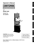
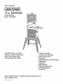
Owner's
Manual
12-ino BANDSAW
3/4 HP MOTOR
Model 119.224000
o Table of Contents
CAUTION: Before using this
product, read this manual and
follow a!l its Safety Rules
and Operating instructions.
® Full One Year Warranty
® Safety instructions
® Assembly
® Getting to Know Your Bandsaw
® Adjustment
® Operation
o Maintenance
® Electricam Schematic
® Troubleshooting
o Parts List "
Sears, Roebuck
www.craftsman,com
OM-22400-MI
and Co., Hoffman
Estates,
IL 60179, U.S.A.
Table of contents .................................................................................................................................................................................................
2
Futlone year warranty. .............................................................................................................................................................................................
2
Safety instructions ....................................................................................................................................................................................................
2
Assembly .................................................................................................................................................................................................................... 4
Getting to know your bandsaw ...................................................................................................................................................................................... 7
Adjustment ................................................................................................................................................................................................................... 7
Operation ................................................................................................................................................................................................................... 11
Maintenance .............................................................................................................................................................................................................. 11
Electrical schematic ................................................................................................................................................................................................
11
Troubleshooting ......................................................................................................................................................................................................
12
Parts list .............................................................................................................................................................................................................
!3
If this Craftsman tool fails due to a defect in material or workmanship within one
year from the date of purchase, CALL 1-800-4-MY-HOME® TO ARRANGE FOR
FREE REPAIR.
If this tool is used for commercial or rentaI purposes, this warranty will apply for
only ninety days from the date of purchase.
This warranty applies only whiIe this tool is in the United States.
This warranty gives you specific legal rights, and you may also have other rights,
which vary, from state to state.
Sears, Roebuck and Co., Dept. 817WA, Hoffmarl Estates, IL 60179
GENERAL
SAFETY WARNINGS
KNOW YOUR POWER TOOL. Read the owner's manual carefuIly. Learn the tool's applications, work capabilities, and its specific
potential hazards.
Always Ground All "fools.
If your tool is equipped with a three-pronged plug, you must plug it into a three-hole electric receptacIe. If you use
an adapter to accommodate a two-pronged receptacle, you must attach the adapter plug to a known ground. Never
remove the third prong of the plug.
Always Avoid Dangerous Environments.
Never use power tools in damp or wet locations. Keep your work area well lighted and clear of clutter.
Always Remove the Adjusting Keys and Wrenches from Tools after Use,
Form the habit of checking to see that keys and adjusting wrenches are removed from the tool before turning it on,
Always
_
Keep Your Work
Area
Clean.
Cluttered areas and benches invite accidents.
Always Keep Visitors Away from Running Machines,
All visitors should be kept a safe distance from the work area,
Always make the Workshop Childproof,
Childproof with padlocks, master switches, or by removing starter keys,
Never operate
a tool while under the influence
2
of drugs,
medication,
or alcohol.
Always Wear Proper Apparel.
Never wear loose c!othtr_g or jewelry that might get caught in moving parts, Rubber-soled footwear is
recommended for the best footing.
Always Use Safety Glasses and Wear Hearing Protection.
Also use a face or dust mask if the cutting operation is dusty.
Never Overreach.
Keep your proper footing and balance at all times.
Never Stand on Tools.
Serious injury could occur if the tool is tipped or if the cutting tool is accidentally contacted,
Always Disconnect Tools.
Disconnect tools before servicing and when changing accessoriessuch as blades, bits, and cutters.
Always Avoid Accidental Staring.
Make sure switch is in "OFF" positionbefore plugging in cord.
Never Leave Tools Running Unattended.
Always Check for Damaged Parts,
Before initial or continual use of the tool, a guard or other part that is damaged should be checked to assure that
will operate properly and perform its intended function. Check for alignment of moving parts, binding of moving
parts, breakage of parts, mounting, and any other conditions that may affect its operation. A guard or other
damaged parts should immediately be properly repaired or replaced,
SPECIAL
1.
2.
3.
4.
5.
6.
7.
8.
9.
10.
SAFETY
RULES FOR BANDSAWS
Always stop the Bandsaw before removing scrap pieces from table.
Always keep hands and fingers away from the blade.
Never attempt to saw stock that does not have a flat surface, unless a suitable support is used,
Always hold material firmly and feed it into the blade at a moderate speed.
Always turn off the machine if the material is to be backed out of an uncompleted cat.
Check for proper blade size and type for thickness and type of material being cut.
Make sure that the blade tension and blade tracking are properly adjusted,
Make "relief' cuts before cutting long curves.
Release blade tension when the saw will not be used for a long period of time.
Note and follow the safety warnings and instructions that appear on the lower door.
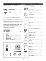
1. TOOLS
REQUIRED
LIST OF LOOSE PARTS IN BAG
FOR ASSEMBLY
Item
Item
Description
_o--_hiUipsScrewdriver
Description
Q'ty.
2-1/2" Dust port ..............................................
............................... 1
Square ...................................................... 1
AND CHECKING
1
Hex. Socket head cap screw M6x12 .............. 2
Adjustable Wrench ................................. 1
2. UNPACKING
Q'ty.
CONTENTS
Washer 6 .........................................................
2
Blade tension knob..: .......................................
1
Crank handle ..................................................
1
Hex, Nut M6 .....................................................
Model 119.224000 12" Bandsaw is shipped complete in one box:
Hex. Bolt MBx45 ..............................................
a. Separate all parts from carton and check each item with "Table
of Carton Contents" to make sure all items are accounted for,
before discarding any packing material.
Hex. Nut M8 .....................................................
i
b. Remove the protective oil that is applied to the table, Use any
ordinary house hold type grease and spot remover.
c. Apply a coat of paste wax to the table to prevent rust. Wipe all
parts thoroughly with a clean dry cloth,
Wing nut M6.................................................... 1
I
Washer
6.........................................................11
l,uho
..........................................................
!
J
Hex, Socket head cap screw M6x45.............. 1
CARTON CONTENTS
Item
Description
A
B
C
D
E
F
G
H
I
Main Machine .................................................................. 1
Rip Fence ........................... ...................................i........1
Table....................................................................................
1
Guide Rai!....................................................................... !
Open StandAssembly ........................................................
1
Owner's Manual ............................................................. 1
Rip Fence Carder...............................................................1
Bag of Loose Parts ........................................................ 1
Upper Table Trunnion Assembly. .................................... 1
Tool holder...................................................... !
Q'ty.
0
B
A
Pan head screw M5xlO ..................................
2
M3 Hex "L _ wrench .........................................
M4 Hex "L" wrench ........................................
M5 Hex "L" wrench .........................................
1
I
!
Fence adjusting knob .......................................
1
Carriage bolt M8x5O........................................
1
Bolt guide .........................................................
1
Washer 8 .........................................................
1
Wing nut M8 .....................................................
1
Carriage bolt M6x40 ........................................
2
Washer 6 .........................................................
2
Washer 6 .........................................................
2
Knurled nut M6 ................................................
2
Wing screw M8...............................................4
Washer8 .........................................................4
F
G
4
Hex, Bolt M8x16 ..............................................
4
Lock washer 8 ................................................
4
:_ !t4_T_AL ASSEMBLY
H_{::machine is supplied partly assembled. Prior to use, the following items have to be installed: Open stand, 2-1/2" dust port, Table, Rip
Fa_co, Blade Tension Knob, Foot I;older, and Crank handle.
W.#.RN_NG: To avoid injury, do not attempt to run or use this machine until all parts are assembled and working properly.
a, A;:;sernbly the opea stand
- CI,eck contents against the parts list.
- Fasten fient panel on to paired legs, using hax carriage bolts, washers and hex nuts. Do not fully tighten.
Fasten side panel on to front panel / paired legs assemblies using remaining hex carriage bolts, washers and hex nuts.
•- Fasten the front and side beams on the paked legs with hex carriage bolls, washers and hex nuts.
- Set stand in an upright position, whilst ensuring that the holes on the top edge of the panels line up sufficiently to al!ow hex head
screws to pass through, lighten fuity the hex carriage bolts and hex nuts.
Press lubber feet on to the end of stand legs.
With assistance lift bandsaw and carefully position in place on top of stand.
- :qx iu position using hex head screw, through washer, bandsaw base, stand, washer and secure on underside with hex nut. Repeat
procedure for all four corners before tightening flJily
%t&iXNING:
tb/',void back'injuw, get help lifting the bandsaw Bend your kness, lift with your legs, not your back.
Pa_rts _ist
_te[_iNo.
I
2
3
4
5
6
7
8
9
i 0
/1
12
Descriptie_l
Front beam.
Side beam
Legs
Side panel
Front panel
Ilex nut
Washer
H,ex carriage bolt
Hex nut
Washer
'lex head screw
Rubber foot
Q'ty
2
2
4
2
2
24
24
24
4
8
4
4
ji
"1'1
Bandsaw open stand
Parts Diagram
@
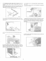
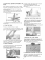
b, Assemble the 2-1/2" dust port to the bandsaw frame with Hex,
socket head cap screw and washer. Place the 2-1/2" dust port on
to the side or the bandsaw frame.
Locate two Hex. socket head cap screws and two washers [rein
the bag of loose parts. Mount the dust port to the bandsaw frame
and install a Hex. socket head cap screw with washer in each
hole then tighten with M5 Hex "L" wrench. (See FIG,l)
d. Fasten the guide rail with four aach wing screw and washer to
the table. Use the hex socket head cap screw, weans'n"ana wtg
r_utfor correcting the working table tla/ness. (See FIG 3
c. Assemble the upper table trunnion to the lower table trunnion
with Carriage Bolt, Glide Piece, Washer and Wing Nut. Place the
table on to the upper table trunnion, taking care when passing the
saw blade through the slot of the table (See FIG. 2).
Locate four hex bolts and four lock washers from the bag of loose
pads. Mount the table to the upper table trunnion and install a bolt
with washer in each hole, then tighten with adjustable wrench.
e.Toassemble
theripfence,takethefencecarrier(A)
andattachit
totheguideraiI(B)usingtheM8x50
carriage
bolt(C)
andthewirlg
net(D).
Fitthefence(E)
tothefencecarrier
withthetwoknurled
nuts(F)
end
M6x40
carriage
bolts(G)
andusethefenceadjusting
knob(H)
for
adjustment
andtolockinposition.(See
FIG.4)
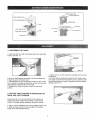
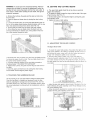
h. The bendsaw has a 2-I/2" dust port and 4" dust port included.
(See Fig. 8)
it is recommended that when in use, the bandsaw is connected to
a suitable dusi collectoL
[2-1/2" dust port
FIG. 4
Ihe tip fence on this baedsaw can be used on either side of the
blade by tixing tim fence to tbe appropriate side of the fence carrier.
(See FIG.5)
i. Assemble the tool holder to the column of the bandsaw with two
pan head screws. Locate two pan head screws from the bag of
loose parts. Mount the toot holder to the column and install a pan
head screw in each hoIe, then tighten with Phillips screwdriver.
(See FIG.9)
!
I
!
[
[. P!ac_ the blade tension knob on to the bIade tensioner (See
FG6)
j. Attach the crank handle to the belt tension crank arm with the M6
Hex. nut. (See FIG.10
g.To ensure sufficient upright stability of the machine it should be
bolted to open stand (See the previous instruction hew to place the
rnachine on to the open stand ). For this purpose 6ram mounting
holes are provided in the machine's base. (See FIG.7)
o
_,
_
!!_ ¸_
_F
_
[6mm mounti0_g
ho_
-
FIG.7
6
_
_,Blade
tension knob
Ig knob
Blade tracking knob_
Lock swi
Motor
4" Dust
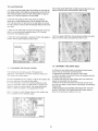
1. CENTERING
THE TABLE
a. Loosen the four hex. bolts mounting the table to the upper table
trunnion. (See FIG. 11)
b. Move the table sideways as required, until the saw blade runs
through the center of the table insert.
c. If the adjustment of "b" is not enough to center the table, loosen
the four flange nuts holding the lower table trunnion and move the
table sideways to place the table in the center.
d. Re-tighten hex. bolts for trunnion, recheck the saw blade
position.
2. SETTING TABLE SQUARE
RIGHT AND LEFT POSITION
TO SAW BLADE
ON
Loosen the wing nut on the lower table trunnion and place a
suitably sized square against the saw blade on right and left
position. If the table requires adjustment, proceed as follows:
a. Using a wrench, release the hex. nut on the frame. (See FIG.12)
b. Place the wrench on the hex. bolt and adjust until the table
square to the saw blade.(See FIG.12)
c. Tighten the hex. nut and recheck the saw blade and the table for
squareness.
d. Lock the table into position and check that the indicator reads
zero degree on the side of lower table trunnion. Loosen the screw
securing the indicator and reset if necessary to give zero degree
reading. (See FIG. 13)
3. SETTING
BLADE
TABLE
SQUARE
FRONT AND BACK
OF
Place a suitably sized square against the saw blade on back and
force position. If the table requires adjustment, proceed as follows:
b. Horizontal alignment of the rip fence is made by adjusting the
two knurled nuts and the fence adjusting knob.
The fence should be aligned with the table slots along its
length.(See FIG. 17)
a. Using a wrench, release the flange nut on the lower table
trunnion. (See FIG.14)
b. Place the M5 Hex %" wrench on the hex. socket set screw and
adjust untiI the table is square to the saw blade on the front and
back pesition.(See FIG.14)
6. ADJUSTING
c. Tighten the flange nut and recheck the saw blade and the table
for squareness.
4. TILTING
THE TABLE
THE RIP FENCE
GUIDE SCALE
To adjust the rip fence scale loosen the four wing screws below
the table and move the scale and the guide rail sideways to
adjust. Re-tighten the wing screws when the adjustment is
correct, (See FIG.17)
The adjustment may be checked by setting the rip fence to a
thickness and cutting a test piece.
When the adjustment is correct the thickness of the test piece will
correctpond with the rip fence scale setting.
For bevet cuts, the table tilts 0 through 45 degrees.
a. To tilt the table, loosen the wing nut on the table trunnion, set the
table to the required angle and tighten the wing nut again (See FIG.
f5).
FIG. 17
7. ADJUSTING
b. It is recommended to verify the correct angle setting using an
angle guide, or by making trial cuts in scrap wood. Adjust the
indicator accordingly by using a phillips head screwdriver.
5. FENCE
THE BLADE
TENSION
To loosen the tension of the blade, turn the blade tension knob
counter clockwise and the tension indicator will be lower. To
tighten the tension of the blade, turn the tension knob clockwise,
and the tension indicator will rise.(See FIG.18)
ADJUSTMENT
a. Vertical alignment of the rip fence is made by adjusting the two
knurled nuts and the fence adjusting knob.
The fence should be adjusted vertically with a suitable square
placed on the table surface.
8. CHANGING
AND ADJUSTING
THE SAW BLADE
This bandsaw is factory-equipped with a general-purpose wood
cutting blade, the saw blade is set prior to delivery.
To change the saw blade, the following procedure must be
followed:
WARNING:
Toavoidinjury from
unexpected starting, whenever
changing the saw blade or carrying out adjustments, switch the
bandsaw off a.nd remove the power cord from the main outlet, To
avoid injury to hands when handling the saw blade, wear gloves
whenever necessary.
a. Remove the rip fence, the guide rail, the wing nut and screw
from the table.
b. ()pen the upper and lower doors by turning the door locldng
knobs.
c. Loosen the blade tension by turning the blade tension knob on
the top of the upper wheel housing counterclockwise until the saw
blade has slackened (viewed from above) (See FIG, 19).
d. Remove the saw blade from the upper and lower wheels.
e. When fitting the new saw blade ensure the blade teeth are
pob_ting downwards and towards you at the position where the
saw blade passes through the table.
10, SETTING
THE
CUTTING
HEIGHT
a. The upper blade guide should be set as close as practical
against the workpiece.
b. To adjust this height, loosen the wing nut at the side of the upper
wheel housing. (See FIG. 21)
c. Set the blade guide to the required height by turning the guide
post adjusting knob.
d. Tighten the wing nut after setting.
I1, ADJUST)NG
THE BLAD):_ GU_Di£S
The Upper Blade Guide
h Re-tension the new saw blade and check the saw blade tracking
by turning the t._pperwheel by hand. The saw blade should run in
the center of the handsaw wheeIs.
g. If needed adjust the tracking of the saw blade, proceed as
mentioned below" TRACKING THE SAW BLADE"
h. Replace the rip fence, the guide rail, the wing nut and screw to
the table.
i. Close the upper and lower doors by turning the door locking
knobs before reconnecting the power supply.
a. To adjust the upper blade guides, first position the right and lei
roller guides relative to the blade by loosening gle lock nut !:1G.22
and rnoving the guide caoier until both io[ler guides are apgro;d.
ma[ely I/1(P behind [he gullets of the saw blade.
b. Set both rol)er guides to within ti32' of the saw blade by
releasing the guide adjusting screw [:1G.22 on each side of the
saw b(ade through turning tile micro-adjusting knobs. Do not sei
the roller guides too close as this wiit adversely affect the life or fl-e
saw blade.
Guide
9. TRACK_NGTHEBANDSAWBLADE
Set the tracking o[ the saw blade before setting the blade guides.
Once the saw blade is installed and tensioned, track the saw
blade by adjusting the tracking knob by hand (See FIG. 20). The
saw blade should run in the center of the baodsaw wheels. When
the correct adjustment is achieved lock the tracking knob with the
wing nut.
c. Adjust the rear miler guide to be just clear of the back or tie saw
blade releasing the gL_ide adjusting screw FIG.23 through t_lrnirJg
the micro-adjusting knob.
d. When the correct adjustment is reached, lock the roller guide ir
position with the guide adjusting screw FIG.23
Micro-adjusting
[{nob
FIG, 23
The Lower Blade Guide
For the high speed 3000 ftimin, the belt should be fitted to the rear
pulley on both the motor and bandwheeL (See FIG.26)
a. To adjust the lower blade guides, first position the right and left
roller guides relative to the blade by loosening the lock nut FIG.24
and moving the guide carrier until both roller guides are approximately 1116" behind the gullets of the saw blade
b. Set both roller guides to within 1/32" of the saw blade by
releasing the guide adjusting screw FIG.24 through turning the
rnicro adjusting knobs on each side of the saw blade. Do not set
the roller guides too close as this will adversely affect the life of the
saw blade.
c. Adjust the rear roller guide to be just clear of the back of the saw
blade by unIocking the guide adjusting screw FIG.24 through
turning the micro-adjusting screw.
d. When the correct adjustment is reached, lock the roller guides in
position with the guide adjusting screws FIG.24
For the low speed 1450 fl/min, the belt should be fitted to the front
pulley on both the motor and bandwheel. (See FIG.27)
t3. CHANGING
12, O_4ANGING
THE BLADE
THE DRIVE BELl"
SPEED
a, Release the saw blade tension by turning the blade tension
knob on the top of bandsaw counterclockwise.
b. Released the belt tension by using the crank handle.
c. Using Cclip pliers (not provided) remove the retaining ring from
the center of the lower wheel.
d. Carefully slide the lower wheel forward and at the same time
release the saw blade from this wheel.
e. Remove the old drive belt and fit the new belt. (ensure ribs in
drive belt are seated correctly before reassembling and tensioning
the drive belt)
f, Follow procedures for CHANGING AND ADJUSTING ]'HE SAW
BLADE & TRACKING THE BANDSAW BLADE, before restoring
power to the bandsaw and settina ur_for use
This bandsaw has two blade speeds 1450 feet/rain for
hardwoods, soree plastics and certain nonferrous metals and
3000 feet/rain for ell o[heI timber.
ihe Iowet bandwheeI has bNo, integral, multi-vee form pulleys and
the motor shaR has a twin multFvee tbrm pulley.
Th,_ @ive belt passes around lhe bandwheel pulley, the motor
pulley and the tension wheel The belt tension is released and
app!ied by using tire cranked handle. This moves the tension
wheel arid allows the speed to be changed.(See FIG.25)
Sefome changing the speed always make sure the machine has
bee_ a_,plcgged from the electrical supply.
Bandwheel
pulle
Crank handle ]
FIG. 25
t0
WARNING: Before star_ing check if any part of your bandsaw is
missing, malfuctioning, has been damaged or broken.., such as
the motor switch, or other operation control, a safety device or the
power cord, turn the bandsaw off and unplug it until the particular
part is properly repaired or replaced.
For best results the saw blade must be sharp. Select the right saw
blade for the job, depending on the thickness of the wood the cut to
be made. The thinner and harder the wood, the finer the teeth of
the saw blade. Use a fine tooth blade for cutting sharp curves,
The machine
make straight
pushing it, as
saw blade to
The saw blade cuts on a continuous downstroke. To avoid injury
when hands are unavoidably near to the saw blade, they should
be placed on either side of the blade, not in line with it. Use a
push stick whenever possible when working in close proximity to
the saw blade.
is especially suited for cutting curves, but will also
cuts. Do not attempt to turn the workpiece without
this may cause the werkpiece to get stuck, or the
bend.
The rip fence is to enable safe and accurate straight cuts of the
workpiece, usually in the same direction as the grain of the timber.
Start the bandsaw by turning the lock switch on and wait for the
bandsaw to come to full speed before starting to cut. Never start
the bandsaw with the workpiece in contact with the saw blade.
The tiltable tabIe is used for bevel cuts.
WARNING: When sawing with the rip fence and a tilted table, the rip
fence must be installed on that side of the table which is tilted
downward.
Slowly feed the workpiece towards the saw blade, putting only light
pressure on it. With both hands, firmly hold the workpiece down on
the table, and feed it towards the saw blade slowly.
WARNING:
To avoid injury due to unexpected starting, before
cleaning or carrying out maintenance work, switch off and disconnect the bandeaw from the power source.
Regular maintenance of the handsaw will prevent unnecessary
problems.
a. Keep the table clean to ensure accurate cutting.
b. Keep the outside of the machine clean to ensure accurate
operation of alI moving parts and prevent excessive wear.
c, Keep the ventilation slots of the motor clean to prevent it from
overheating.
d. Keep the inside (near the saw blade, etc.) clean to prevent
accumulation of dust. Use dust collection if possible.
e, To prolong the life of the saw blade, when the bandsaw is not in
use for extended periods, release the saw blade tension. Before
reusing the bandsaw ensure that the blade is re-tensioned and
tracking is checked,
Never use water or other liquids to clean the bandsaw. Use a dry
brush,
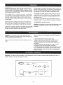
WARNING;
This machine must be grounded. To avoid electrocution or fire, any repairs to electrical system should be done onIy by a
qualified electrician, using genuine replacement parts.
SWITCH_-'---'-_
LAMP
SWITCH
tl
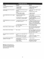
Problem
Diagnosis
Remedy
The machine does not work when
switched on.
1. No power supply.
2. Defective switch.
3 Defective motor.
1. Check the cable for breakage.
2. Replace the lock switch.
3. Defective motor.
The saw blade does not move with the
motor running.
1. The blade tension knob has not been
tightened.
2. The blade has come off one of the
wheels.
3. The saw blade has broken.
4. The drive belt has snapped.
1. Switch off the motor, tighten the blade
tension knob.
2. Open the doors and check.
1, Rip fence for cutting not used.
2. Feed rate too fast.
I. Use a rip fence.
2. Put light pressure on the workpiece.
Make sure the saw blade does not bend.
3. Try a new saw blade,
4. Adjust the blade guides (see ADJUSTMENT instructions).
The saw blade does not cut in a straight
line.
3. The blade teeth are dull or damaged.
4. Blade guides not suitably adjusted.
The saw blade does not cut, or cuts very
slowly.
1. The teeth are dul!, caused by cutting
hard material or long use.
2. The saw blade was fitted the wrong
way on the bandsaw.
3. Replace the blade.
4. Replace the belt,
1. Replace the saw blade, use a 6 T.RL
saw blade for wood and soft material.
Use a 14 T.RI. saw blade for harder
materials. A 14 T.RI. saw blade always
cuts slower due to the finer teeth and the
slower cutting performance.
2. Fit the saw blade correctly.
Sawdust builds up inside the machine.
This is normal
Clean the machine regularly. Open the
doors and remove the sawdust with a
vacuum cleaner.
Sawdust inside the motor housing.
This is normal
Clean the ventilating sIots of the motor
with a vacuum cleaner. From time to time
remove the sawdust to prevent it from
being drawn into the housing.
The machine does not cut at 45 or 90
degrees,
1. The table is not at right angles to the
blade.
2. The saw blade is dull or too much
pressure was put on the workpiece,
I. Adjust the table.
The saw blade can not be properly
positioned on the wheels,
1. The wheels are not in alignment or
defective bearing.
2. The blade tracking knob hasn't been
properly adjusted.
3. Inferior saw blade,
Warning: Use of this product can
generate dust containing chemicals
known [to the state of California] to
cause cancer, birth defects or other
reproductive harm.
12
2. Replace the saw blade or put Iess
pressure on the workpiece.
1. Replace bearing.
2. Adjust the blade tracking knob (See
ADJUSTMENT instructions).
3. Replace the saw blade.
\
\
\
\
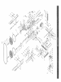
KEY NO.
1
2
3
4
5
6
7
8
9
10
11
12
13
14
15
16
17
18
19
20
21
22
23
24
25
26
27
28
29
30
31
32
33
34
35
36
37
38
39
40
41
42
43
44
45
46
47
48
49
50
51
52
53
54
55
56
57
58
59
6O
61
62
63
64
65
66
67
68
69
70
71
72
73
74
DESCRIPTION
Door locking knob Cap
Hex. Bolt M6x40
KEY NO.
75
76
77
78
79
80
81
82
83
84
85
86
87
DESCRIPTION
Brush
Cardage bolt MSxg0
Motor
Motor cable
Hex. Bolt M6x20
Hex, Nut M6
Lower bearing bolt
Dust port 4"
Dust port 2-1/2"
Hex, Socket head cap screw M6x12
Spring washer 6
Hex. Bolt M6x16
Hax. Socket set screw M6xl0
88
89
90
91
92
Motor pulley
Sliding shaft
Searing 80101
Retaing ring 28
Tension wheel
93
94
Retaing ring 12
Drive belt
95
96
97
98
99
100
Special bex. Nut
Retaining ring 17
Bearing 80203
Retaining ring 17
Tire
Lower wheel
101
102
103
Retaining ring 40
Tapping screw ST3.5x13
Rack
104
105
Blade guide
Slider
106
107
108
109
110
!11
!12
Carriage bolt M8x20
Bolt guide
Wing nut M8
Guide adjusting screw
Micro-adjusting
knob
O-ring
Washer 5
!13
114
115
Long tube
Bearing 80018
Tube
116
117
118
119
120
121
122
Guide adjusting screw
Upper guide body
Hex. BoIt 5t16"×7/8"
Special washer
Ha;< socket head screw M8xl0
Hex. Nut 5/16"
Washer 8
123
124
Upper guide mount
Short tube
125
126
127
128
129
Bearing mount cylinder w/thread
Upper guiae shaft
Micro-adjusting knob bracket/right
Micro-adjusting
knob bracketilett
Pan head screw M4x5
130
131
132
133
134
135
136
137
138
139
140
141
Micro-adjusting knob bracket/rear
Bearing mount cylinder w/thread
Crank handIe
Rex. Nut M6
Belt tension crank arm
Washer 10
Set co!lar
Set screw M5×8
Table insert
Table
Hex. Nut M8
Hex. Bolt M8x45
142
143
144
He×. Socket
Washer 6
Tube
Flange nut M8
Tube
145
146
147
Wing nut M6
Guide rail
Washer 8
Rubber tube
!48
Wing
Door locking knob body
Hex, Nut M6
Slotted insert
Special spdng washer
Lock housing
Washer
Rivet 4x8
Upper door
Leaf spring
Special nut M22
Tongue lock
Spring washer 6
Lock nut M6
Saw blade
Retaining ring 17
Ball bearing 80203
Retaining ring 40
Upper wheel
Tire
Upper beadng bolt
Wheel carrier bracket
Spdng washer 16
Hex. Nut M16
Adjusting
screw
Blade tension indicator
Spdng
Star lock
Mount shaft
Cable wtplug
Blade tensioner
Washer 8
Tension bracket
Flange nut M8
Blade tensioner
Lock switch
Pan head screw M4x12
Switch cover plate
Pan head screw M4x8
Washer 4
Lock washer 4
Tool holder
Pan head screw M5xl0
Bushing ring
Frame
Top plug
Roll pin 5x18
Blade tension knob
Hex. Bolt M8x16
Washer 8
Wing nut M8
Hex. Nut M8
Blade tracking knob body
Hex. Bolt MSx70
Blade tracking cap
Working light
Adjusting knob cap
Adjusting knob body
Tube
Rivet 3x7
Clear window
He>(. Bolt M6x16
Guide bracket
Lock washer 6
Hex. Nut M6
Spring washer
Hex. Nut M20
Gear
Washer 6
Lock nut M6
head cap screw M6x45
screw M8
14
KEY NO.
149
15_0
151
152
153
DESCRIPTION
Fence
Carriage bolt M6x40
Washer 6
Knuded nut M6
Hex. Nut M6
154
155
156
Fence adjusting knob body
Fence adjusting knob cap
Hex. Bolt M6x40
157
!58
159
160
161
162
163
164
Carriage bolt M8:<50
Bolt guide
Tapping screw 3.5x9.5
Indicator
Rip fence carrier
Washer 8
Wing nut M8
Pan head screw M4x6
165
166
167
168
169
t70
Lower blade guard
Lower guide body
Micro_adjust knob bracketJrear
Washer 4
Pan head screw M4x5
Hex socket set screw M6xl0
171
!72
173
174
175
176
177
178
179
180
181
182
183
184
185
186
Bearing mount cylinder w/thread
Long tube
O-dng
Micro-adjusting
knob
Washer 5
Beadng
Tube
Guide adjusting screw
Bearing mount cylinder
Lower guide shaft
Hex. Socket set screw M6×10
Lock nut M6
Washer 6
Lower guide mount
Hex. Nut M6
He×. Socket set screw M6x35
187
188
189
190
191
192
193
Micro-adjusting
knob
Pan head screw M4x5
Micro-adjusting
knob bracket/rear
Lower guide mount seat
Washer 6
Hex. Bolt M6×35
Lock nut M6
194
195
196
197
198
199
200
Spring washer 6
Tongue lock
Special nut M22
Leaf spdng
Lower door
Rivet 4x8
Washer
201
202
203
204
Lock housing
Special spring washer
Slotted insert
Hex. Nut M6
205
206
Door locking knob body
Hex. Bolt M6x40
207
208
209
210
211
212
213
214
215
216
217
218
Door lock knob cap
Carriage bolt M8x50
Glide piece
Upper table trunnion
Tapping screw ST3,5xg.5
Indicator
Lock washer 8
Hex, Bolt M8x16
Flange nut M8
Rex. Socket set screw M6xl0
Lower table trunnion
Washer 8
219
Wing nut M8
220
Carriage
bolt M8x20
Your Home
For repair-in your home-of all major brand appliances,
lawn and garden equipment, or heating and cooling systems,
no matter who made it, no matter who sold it!
For the replacement parts, accessories and
owner's manuals that you need to do-it-yourself.
For Sears professional installation of home appliances
and items like garage door openers and water heaters.
i oS00°4=MY=HOME® (1o800o469o4663)
Call anytime, day or night (U.S.A. and Canada)
www.sears.com
/
www.sears.oa
Our Home
For repair of carry-in items like vacuums, lawn equipment,
and electronics, call or go on-line for the location of your nearest
Sears Parts & Repair Center.
!7
1o880=488-12:22
#
Call anytime, day or night (U.S.A. only)
www.sears.com
_!
To purchase
agreement
or maintenance
agreementa protection
(Canada) on
a product(U.S.A.)
serviced by Sears:
i _800-827o6655
(U.S.A.)
Para pedir servicio de reparaci6n
a domicilio,
y para ordenar
piezas:
1-888-S U-HOGAR sM
:_i_
,
(1-888-784-6427)
1-800=361-6665
(Canada)
Au Canada pour service en fran_ais:
1-SO0-LEoFOYER
Mc
(I-800-533-6937)
www.sears.ca
.....
..........
Sea/
® Registered Trademark / TMTrademark / SMService Mark of Sears, Roebuck and Co.
® Marca Registrada / TMMarca de F&brica / SMMarca de Servicio de Sears, Roebuck and Co,
MC
Marque de commerce / MD Marque deposee de Sears, Roebuck and Co.
© Sears, Roebuck and Co.