1
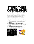
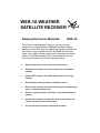
WSR-1A WEATHER
SATELLITE RECEIVER
Ramsey Electronics Model No.
WSR-1A
Can’t trust the weatherman? Now you can be your own
weatherman with the Weather Satellite Receiver! Observe
weather events while they are happening, instead of waiting for
the news! A very sensitive receiver, the WSR-1A will return
sharp, clear, high contrast images with a maximum resolution
down to a mile! Be amazed at the new perspective you will
have on the weather and its ever-changing ways!
•
High sensitivity front end for noise-free transmissions.
•
Automatic scanning for all non-geo-synchronous VHF weather
satellites
•
Decodes APT satellites. Ex: NOAA, Meteor, and Feng Yun type
satellites.
•
Demodulating board and software available for the PC.
•
Easy to follow assembly instructions that lead you through step-bystep to a completed working unit
•
All that is required to begin receiving is a demodulator board and
software.
•
Preamp also included to increase the clarity of your images and
“stretch” the span of the received image.
•
Fun to build and the results are well worth the effort!
WSR-1A• 1
RAMSEY TRANSMITTER KITS
• FM-10 FM Stereo Transmitter
• FM-1,2,3,4 FM Wireless Microphones
• PB-1 Telephone Transmitter
RAMSEY RECEIVER KITS
• FR-1 FM Broadcast Receiver
• AR-1 Aircraft Band Receiver
• SR-1 Short-wave Receiver
• AA-7 Active Antenna
• SC-1 Short-wave Converter
RAMSEY HOBBY KITS
• SG-7 Personal Speed Radar
• SS-70 Speech Scrambler
• URC-1 Universal Remote Control
• SP-1 Speakerphone
• MD-3 Microwave Motion Detector
• PH-10 Peak hold Meter
• LC-1 Inductance-Capacitance Meter
RAMSEY AMATEUR RADIO KITS
• FX Series VHF and UHF Transceivers
• HR Series HF All Mode Receivers
• QRP Series HF CW Transmitters
• CW-700 Micro Memory CW Keyer
• PA Series VHF and UHF Power Amplifiers
• Packet Computer Interfaces
• QRP Power Amplifiers
RAMSEY MINI-KITS
Many other kits are available for hobby, school, Scouts and just plain FUN.
New kits are always under development. Write or call for our free Ramsey
catalog.
WSR-1 SATELLITE RECEIVER KIT INSTRUCTION MANUAL
Ramsey Electronics publication No. MWSR-1A Revision 2.3A
First printing: Sept 1995
COPYRIGHT 1995 by Ramsey Electronics, Inc. 793 Canning Parkway, Victor, New York
14564. All rights reserved. No portion of this publication may be copied or duplicated without the
written permission of Ramsey Electronics, Inc. Printed in the United States of America.
WSR-1A• 2
Ramsey Publication No. WSR-1A
Price $5.00
KIT ASSEMBLY
AND INSTRUCTION MANUAL FOR
WSR-1A WEATHER
SATELLITE RECEIVER KIT
TABLE OF CONTENTS
Introduction to the WSR-1A .............
Parts list ...........................................
Strategy and Tips .............................
Circuit Description ............................
Construction .....................................
Schematic ........................................
Casing it up ......................................
Initial Testing ....................................
Trouble Shooting .............................
Antennas ..........................................
Building an Antenna .........................
Turnstile Wiring ................................
Preamp ............................................
How To Receive a Transmission .....
Parts Layout .....................................
Specifications ...................................
Warranty ..........................................
4
6
8
9
11
20
24
25
27
28
30
31
33
34
35
36
37
RAMSEY ELECTRONICS, INC.
793 Canning Parkway
Victor, New York 14564
Phone (716) 924-4560
Fax (716) 924-4555
WSR-1A• 3
INTRODUCTION TO THE WEATHER SATELLITE RECEIVER
The days of guessing the weather by looking at the clouds overhead have just
ended. Now you can look at the clouds from above! This project will allow you
to receive pictures from satellites 600 km overhead. A typical NOAA satellite
can cover nearly 1/16 of the earth in a single pass! In New York, we are able to
clearly capture images from mid-Hudson bay (where there was still ice in late
spring), all the way down past Cuba, as well as spanning from Wisconsin to far
out in the Atlantic Ocean. The clarity of the image was enough to see the
individual Finger Lakes (in New York), and shadows on the underside of
thunderstorms.
This receiver kit allows you to receive weather satellite transmissions on the
VHF band, where most of the polar-orbiting satellites are located. You will
recognize these transmissions on the news when you see the time lapse of the
clouds darting across the countryside. The weather man in this case has taken
multiple images on the computer, aligned and pieced them together, and then
run through one image after the other. It is possible to do this same thing with
this kit and the proper software.
The way in which a weather satellite works is fairly simple. Just think of your
office fax machine as an example. The satellites circle the Earth going north to
south back to north again almost directly over the poles, which is why they call
it a polar orbit. This means that the satellite will cover every location on the
Earth at least twice per day. With a good antenna, and partly because of
overlap of consecutive orbits, you can conceivably receive the same satellite up
to six times a day! Notice though that the image received from polar orbits will
be upside down on every other pass.
The satellite retrieves the data in a linear fashion, one line at a time using a
scanning radiometer. The scanning radiometer transmits the equivalent of a
single television horizontal line as the satellite circles the earth. The system
uses a series of optics and a motor driven rotating mirror system to receive a
very narrow line of the image of the Earth. Each line is received at a right angle
to the satellite’s orbital track, so as the satellite circles the earth, a line is
received from west to east or east to west depending on the orbit of the
satellite. The total image is received from north to south or south to north
depending on the orbit also, and this motion is what relays the equivalent of the
vertical scan in a television. You can continue receiving this satellite as long as
it is within the line of sight.
Since all of the receivable satellites are similar, we will describe the ones you
will most commonly receive. The NOAA/TIROS satellites, during the first half of
the transmission, send visible light data to the receiver at the same time they
are taking in the view. Meanwhile during the same part of the scan, they are
recording the infrared view. During the second half of the scan, while the
WSR-1A• 4
sensors are facing away from the earth, it sends the infrared data. The user
then sees the data as two images side by side, on the left the visible light data
is seen, and on the right, infrared data is seen. In between the images are
synchronization pulses that help computers to align the individual lines
precisely.
These particular satellites continuously transmit an FM signal modulated with a
2400Hz tone. This tone is very precise in frequency so the image seen is
aligned properly. The 2400Hz tone is AM modulated with the intensity of the
current view of the earth. The brighter or colder the point on the earth, the
higher in amplitude the 2400Hz signal is.
The receiver demodulates the FM signal and retrieves the 2400Hz tone. The
detector board in the computer will then find the peak amplitude of each wave
of the 2400Hz tone, and each peak, upper and lower now represents a single
pixel on the screen. For the NOAA/TIROS satellites, each horizontal line
represents 2400 pixels, since the incoming frequency is 2400Hz, and the
scanning radiometer rotates twice per second. The full 12 minute pass of a
NOAA satellite requires approximately 3.5 MB (3.5 million 8 bit pixels) of
storage! This is much more data (pixels) than can be seen on a super VGA
screen at any one time.
NOTE TO NEWCOMERS: If you are a first time kit builder you may find this
manual easier to understand than you may have expected. Each part in the kit
is checked off as you go, while a detailed description of each part is given. If
you follow each step in the manual in order, and practice good soldering and kit
building skills, the kit is next to fail-safe. If a problem does occur, the manual
will lead you through step by step in the troubleshooting guide until you find the
problem and are able to correct it.
WSR-1A• 5
RAMSEY WSR PARTS LIST
Semiconductors
1 LM386 Audio Power Amplifier (U1)
1 MC13135 FM Demodulator (U2)
1 MC145170 Digitally controlled Phase Locked Loop (U3)
1 MC68HC705K1 Microcontroller (U4)
1 74HC138 3 to 8 Line Decoder (U5)
1 LM358 Operational amplifier (U6)
1 BB505 Varactor Diode (D1)
5 2N3904 NPN transistors (Q3,Q4,Q5,Q6,Q7)
3 2SC2498 or 2570 NPN transistors (Q1,Q2,Q8)
8 Red mini LEDs (D2,D3,D4,D5,D6,D7,D8,D9)
1 7805 5 Volt regulator (VR1)
Resistors
1 4.7 ohm resistor (yellow-violet-gold)(R9)
1 100 ohm resistor (brown-black-brown)(R30)
1 270 ohm resistor (red-violet-brown)(R38)
3 470 ohm resistors (yellow-violet-brown)(R2,R17,R32)
11 1K ohm resistors (brown-black-red) (R7,R15,R21,R24,R26,R29,R31,R34,R35,
R40,R42)
1 3.3K ohm resistor (orange-orange-red)(R14)
13 10K ohm resistors (brown-black-orange)
(R1,R4,R6,R12,R18,R19,R20,
R22,R23,R27,R28,R33,R39)
1 22K ohm resistor (red-red-orange)(R16)
4 47K ohm resistors (yellow-violet-orange)(R3,R36,R41,R43)
1 68K ohm resistor (blue-gray-orange)(R8)
1 100K ohm resistor (brown-black-yellow)(R13)
1 220K ohm resistor (red-red-yellow)(R10)
1 1M ohm resistor (brown-black-green)(R25)
Miscellaneous
1 10.240MHz Crystal (Marked 10.240) (Y2)
1 10.7MHz ceramic filter (looks like capacitor with three leads in a row) (FL1)
1 450kHz ceramic filter (black cube with three leads) (FL2)
1 CBW 137MHz filter (large metal shielded can, two adjustments) (FL3)
1 10K trimmer potentiometer (yellow adjustment marked 103) (R37)
2 10K potentiometer (top mount stand up type, blue body) (R5, R11))
1 Ramsey “diddle stick” plastic tuning tool.
Capacitors
11 .001uF ceramic capacitors (marked .001, 102, or 1n) (C2,C6,C7,C14,C19,C24,
C26,C27,C36,C37,C39)
10 .01uF ceramic capacitors (marked .01, 103, or 10n) (C4,C25,C40,C41,C42,C46,
C47,C48,C54,C55)
3 100pF ceramic capacitors (marked 100, or 101) (C17,C18)
7 .1uF ceramic capacitors (marked .1 or 104) (C20,C22,C28,C33,C34,C35,C38)
WSR-1A• 6
RAMSEY WSR PARTS LIST
Capacitors cont...
4 22pF ceramic capacitors (marked 22) (C29,C44,C45,C53)
1 15pF ceramic capacitor (marked 15) (C30)
2 10pF ceramic capacitors (marked 10) (C31,C32)
1 220pF ceramic capacitor (marked 220, or 221) (C52)
1 2 or 2.2pF ceramic capacitor (marked 2 or 2.2) (C8)
2 39pF ceramic capacitors (marked 39) (C11,C12)
9 10uF electrolytic capacitors (C1,C3,C9,C10,C16,C21,C49,C50,C51)
1 220uF electrolytic capacitor (C13)
1 100uF electrolytic capacitor (C15)
1 1000uF electrolytic capacitor (C5)
1 35pF Trimmer cap (orange top, silver adjuster) (C43)
Inductors
1 LB53303HK variable shielded coil (metal case with orange slug inside) (L7)
4 10uH inductors (blue-green body with brown-black-black-silver stripes) (L2,L3,
L6,L9)
2 4 Turn wire wound inductors (L4, L5)
1 2.2uH inductor (green body with red-red-gold-black stripes) (L1)
1 84885-5 Variable inductor (small metal case with green plastic) (L8)
Hardware, Jacks
1 2 pin header (P1)
1 2.5mm stereo jack (J5)
1 3.5mm phone jack (J1)
1 Power jack (J4)
1 RCA Phono jack (J3)
1 PC mount ‘F’ connector (J2)
3 DPDT switches (S1, S2, S3)
1 Buzzer Speaker (SP1)
1 Main PC Board
1 Daughter Board
2 16 Pin IC sockets
Case and knob parts
1 Case bottom
1 Case top
1 Case front panel
1 Case back panel
3 Decorative switch caps
2 Control knobs
4 Mounting screws
WSR-1A• 7
RAMSEY “LEARN-AS-YOU-BUILD” ASSEMBLY STRATEGY
Be sure to read through all of the steps, and check the boxes as you go to be
sure you didn't miss any important steps. Although you may be in a hurry to see
results, before you switch on the power check all wiring and capacitors for
proper orientation. Also check the board for any possible solder shorts, and/or
cold solder joints. All of these mistakes could have detrimental effects on your
kit - not to mention your ego!
Kit building tips:
Use a good soldering technique - let your soldering iron tip gently heat the
traces to which you are soldering, heating both wires and pads simultaneously.
Apply the solder on the iron and the pad when the pad is hot enough to melt the
solder. The finished joint should look like a drop of water on paper, somewhat
soaked in.
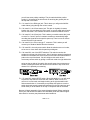
Mount all electrical parts on the top side of the board provided. This is the side
that has little or no traces on it. When parts are installed, the part is placed flat
to the board, and the leads are bent on the backside of the board to prevent the
part from falling out before soldering (1). The part is then soldered securely to
the board (2-4), and the remaining lead length is then clipped off (5). Notice
how the solder joint looks on close up, clean and smooth with no holes or sharp
points (6).
WSR-1A• 8
WSR-1A CIRCUIT DESCRIPTION
The Weather Satellite Receiver is a fairly complex receiver as compared to
most of the other receiver kits that are sold. This receiver contains circuitry
found in very high end receivers and transceivers. This is due to the high
accuracy of reception required to be able to continuously monitor various
satellite transmissions, and be right on frequency every time. The receiver must
also have a very sensitive front end for the satellites that are low on the
horizon, and also for antenna setups that can’t be optimally placed on the
Sears tower. For these reasons we will go through the receiver from the
antenna end to the speaker output, and help you understand what each section
is doing in relation to the flow chart.
If you look at the schematic provided, we will begin at J2, where the antenna is
to be connected. L1 and C4 are for the sole purpose of injecting DC into the
antenna feed line to power an external preamp. The circuitry directly after these
two parts from C11 all the way over to filter FL3 and C14, is a narrow band VHF
preamplifier. This circuitry prevents intermodulation problems and reduces the
general noise while increasing gain and reception.
This amplified signal is then seen by the MC13135 FM receiver chip (U2). This
chip performs the mixing between the PLL LO (Phase Locked Loop Local
Oscillator), and the incoming RF. Then using a detection scheme called
quadrature detection (performed mostly in L7), this part of the circuit
demodulates (converts to audio) the incoming FM signal. There is of course
much more than that to this part of your receiver, but nothing that wouldn’t be
covered in a communications handbook.
The demodulated audio signal is then passed through a low pass filter, which
Lowpass Filter
WSR-1A• 9
allows only frequencies in the needed range to come through. By doing this, it
reduces the noise produced by a weak reception, since noise covers the entire
audio spectrum, but we are only interested in the spectrum around 2400Hz.
After the audio filtering, the audio is first tapped to go to a decoder card on a
PC. This way the adjustment of the volume will not alter the level of the voltage
going to the PC. Next the audio goes through the volume control before going
to the audio amplifier, consisting of U1. This amplifier is capable of putting out
some decent volume, especially combined with the efficiency of the buzzer
speaker provided with this kit.
If you look at pin 16 of U2, the receiver chip, you will see the squelch output.
The squelch is opened when the signal level of the current frequency is high
enough. In the Weather Receiver, this squelch output is used not only to switch
on the output audio when activated, but also to turn on a transistor switch
consisting of Q6, and Q7. This transistor switch allows you to turn on a portable
tape deck or some other recording device to allow you to store satellite images
onto standard audio tapes.
The same squelch signal is also fed to U4, the MC68HC705K1 microcontroller.
This lets the microcontroller know to stop scanning different frequencies while a
signal is being received. This microcontroller is able to send data to the
programmable phase locked loop (U3), and configure it for a different divide by
‘n’. This means that the phase locked loop is able to be adjusted to produce
any frequency within a range, by simply sending it a digital number from the
microcontroller. The microcontroller is just pre-programmed with eight different
numbers representing the eight different frequencies we wish to generate with
the PLL. This allows us to receive the eight different frequencies that the
satellites are on.
U5, the 74HC138 3 to 8 line decoder does just what it sounds like. The
microcontroller sends out a three bit number, or octal, which has eight
possibilities. The decoder takes these possibilities and outputs to only one of
the eight LEDs, therefore lighting the respective LED. These same decoder
chips are commonly used to access different devices on a computer, allowing
for up to eight different devices on this particular chip.
VR1 and the surrounding parts are simply a power supply. The 7805 is a
commonly used 5 volt regulator, which produces the five volts needed by the
microcontroller and display.
Well, we hope the description of this kit helps you to understand what is going
on in your receiver kit, and make it more enjoyable to assemble. Take your time
putting this together and make sure you follow all of the steps properly. We
have greatly enjoyed designing this project for you, and hope that you will enjoy
using it. Now it’s time to get down to it, and begin assembling this project!
WSR-1A• 10
CONSTRUCTION OF THE WEATHER SATELLITE RECEIVER
Sort out all of your parts to begin with, making sure you have all of the parts
required. You can use old egg cartons to hold various parts to make them
easier to find. We will begin building the kit from the back side of the board
where all the jacks will eventually be placed. Make sure to mount parts on the
correct side! You will want to use the parts layout diagram to assist you in
finding where the parts go.
1. Install J4, the power jack. This will be our reference part and will help us
locate where other parts are located on the board.
2. Install C55, a .01uF ceramic capacitor (marked .01, 10n, or 103).
3. We will skip SP1, the speaker buzzer at this time. This will allow us to
mount other parts in this area more easily.
4. Install L6, one of the 10uH inductors (blue-green body with brown-blackblack-silver stripes)
5. Install C42, a .01uF ceramic capacitor (marked .01, 10n, or 103).
6. Install L9, another 10uH inductor like in step 4.
7. Install C46, another .01uF ceramic capacitor (marked .01, 10n, or 103).
8. Install L3, another 10uH inductor.
9. Install C41, another .01uF ceramic capacitor.
10. Install C40, yet another .01uF ceramic capacitor.
11. Install L2, the last of the 10uH inductors.
You have just completed some of the filters that are required to keep the RF
noise generated by computers out of the radio. This helps prevent a noisy
picture and improves reception capability.
12. Install R39, a 10K resistor (brown-black-orange). To
mount as a stand up resistor for best looks, bend the leads so
the resistor stands square to the board before soldering. Keep
it neat!
13. Install Q7, a 2N3904 NPN type transistor. Be sure and mount the flat
side in the same direction as shown on the parts layout.
14. Install Q6, another 2N3904 type transistor (Note previous step).
We have just completed the ‘switch’ for the tape cassette recorder. Now it is
time to begin working on the actual receiver’s PLL and demodulator.
WSR-1A• 11
15. Install C26, a .001uF ceramic capacitor (marked .001, 1n, or 102).
16. Install R15, a 1K ohm resistor (brown-black-red).
17. Install R13, a 100K ohm resistor (brown-black-yellow).
18. Install D1, a BB505 varactor diode (orange glass body with printed
characters marking the part number). This varactor diode allows the phase
locked loop to operate by adjusting the reverse bias voltage on this diode.
This diode is the capacitive part of the local oscillator, and L8 is the
inductive part. As the reverse bias voltage across this diode increases, the
capacitance decreases, therefore the local oscillator’s frequency increases.
This circuit combined with a frequency to voltage converter (phase
detector) are the major components of the phase locked loop. Be sure to
mount this part in the correct direction. The cathode, or the striped end
should be in the same orientation as in the parts layout diagram.
19. Install C25, a .01uF ceramic capacitor (marked 103, .01, or 10n).
20. Install Q8, a 2SC2498 NPN RF transistor. This transistor has very good
characteristics all the way up to 1GHz and more. With low noise and high
gain as part of its repertoire, this part can almost put a GaAsFET to shame.
This transistor amplifies and isolates the VCO output from the PLL chip. Be
sure to mount the flat side in the same orientation as in the parts layout
diagram. Also check that it is not a 2N3904 transistor since the pin outs and
characteristics are not the same!
21. Install R41, a 47K ohm resistor (yellow-violet-orange).
22. Install C39, a .001uF ceramic capacitor (marked .001, or 102).
23. Install R40, a 1K ohm resistor (brown-black-red).
24. Install C36, another .001uF ceramic capacitor (marked .001, or 102).
25. Install R20, a 10K ohm resistor (brown-black-orange). Note this is a laydown resistor, and be sure to use the correct holes.
26. Install C43, a 35pF trimmer capacitor (orange top, silver adjustment).
This part will allow us to get the 10.24MHz crystal running at exactly the
frequency we desire.
27. Install R25, a 1M ohm resistor (brown-black-green).
Most of the parts we are installing right now are parts associated with the phase
locked loop. The next few parts will be associated with D1, the varactor diode.
This will make up the VCO, or voltage controlled oscillator, which will be
precisely controlled by the PLL chip.
28. Install C37, a .001uF ceramic capacitor (marked .001, or 102).
WSR-1A• 12
29. Install C32, a 10pF ceramic capacitor (marked 10).
30. Install R38, a 270 ohm resistor (red-violet-brown).
31. Install C31, another 10pF ceramic capacitor (marked 10).
32. Install C29, a 22pF ceramic capacitor (marked 22).
33. Install L8, a 84885-5 variable inductor (smaller metal case with green
plastic.) This coil is the inductive part of the voltage controlled oscillator of
the PLL.
34. Install C54, a .01uF ceramic capacitor (marked .01, 103, or 10n),
located near J5.
35. Install C4, another .01uF ceramic capacitor.
36. Install Q2, a 2SC2498 NPN RF transistor. This transistor is part of the
preamp to amplify the incoming signal after the RF bandpass filter, and
boost it to a level that is usable by U2. Pay close attention to orientation!
37. Install R3, a 47K ohm resistor (yellow-violet-orange).
38. Install R2, a 470 ohm resistor (yellow-violet-brown).
39. Install C30, 15pF ceramic capacitor (marked 15).
40. Install Q1, the last of the 2SC2498 NPN RF transistors. This is the last
part of the PLL to get the VCO to oscillate. Make sure and place the
transistor in the correct way!
41. Install C27, a .001uF ceramic capacitor (marked .001, 102, or 1n).
42. Install R36, a 47K ohm resistor (yellow-violet-orange).
43. At this point you may want to check your assembly job. Check to make
sure all parts are mounted as closely as possible to the board without
sacrificing neatness, and check all of your solder joints for possible solder
bridges and cold solder joints. We don’t expect you to be an expert at
soldering right from the start, so if you take your time and check as you go,
you will save a lot of time later when you test this out for final operation.
44. Install R30, a 100 ohm resistor (brown-black-brown).
45. Install C24, a .001uF ceramic capacitor (marked 102, .001, or 1n).
46. Install C2, another .001uF ceramic capacitor (marked 102, .001, or 1n)
47. Install C7, yet another .001uF ceramic capacitor.
48. Install C12, a 39pF ceramic capacitor (marked 39).
WSR-1A• 13
49. Install C18, a 100pF ceramic capacitor (marked 100 or 101).
50. Install C11, another 39pF ceramic capacitor (marked 39).
51. Install C17, another 100pF ceramic capacitor (marked 100 or 101).
52. Install C8, a 2pF or 2.2pF ceramic capacitor (marked 2, or 2.2).
53. Install L4, a four turn wire wound inductor (can’t miss em, they look like
tight springs!)
54. Install L5, another four turn inductor.
These two coils you just installed will later be stretched or bent to adjust the
center frequency of the RF bandpass filter you just completed. As these coils
are distorted, the inductance will change, allowing for fine tuning of the
reception and sensitivity of your receiver.
56. Install U2, the MC13135 FM demodulator IC. (24 pin DIP). When
inserting the chip into the IC socket, be sure all pins are properly seated
into the socket. It is very easy to have a pin bent under the chip, making it a
tough problem to find. Remember this when installing all chips! This chip as
we have described earlier demodulates the incoming FM signal using
quadrature detection and other neat features. Make sure that you have
inserted the IC in the correct way, so that the notch or dimple is facing in
the same direction as in the parts layout diagram.
57. Install C19, a .001uF ceramic capacitor (marked 102, .001, or 1n).
58. Install FL1, a 10.7MHz ceramic filter. This is a part that looks much like
a capacitor, but it has three leads instead of two.
59. Install C14, a .001uF ceramic capacitor (marked .001, 102, or 1n).
60. Install FL3. This is the large silver can with two adjustments on top. Be
careful when installing so that you don’t bend any leads over. This part is
known as a “helical filter” and filters the incoming RF even more than the
RF filter we completed earlier, and provides for excellent intermodulation
performance.
61. Install C1, a 10uF electrolytic capacitor. Notice this is the first capacitor
of this type. You want to be sure that you pay close attention to the polarity
markings on this part. In most cases the negative (-) side is marked on the
capacitor, while the positive side (+) is marked on the parts layout. If you fail
to mount this component correctly, the part can fail as well as prevent
proper operation of your project.
62. Install C20, a .1uF ceramic capacitor (marked .1, 104, or 100n)
63. Install R10, a 220K ohm resistor (red-red-yellow).
WSR-1A• 14
64. Install R7, a 1K ohm resistor (brown-black-red).
65. Install R8, a 68K ohm resistor (blue-gray-orange).
66. Install R16, a 22K ohm resistor (red-red-orange).
67. Install C28, a .1uF ceramic capacitor (marked .1, 104, or 100n).
68. Install C33, a .1uF ceramic capacitor (marked .1, 104, or 100n)
69. Install R24, a 1K ohm resistor (brown-black-red).
70. Install TP4 with a 1/2” piece of scrap
component lead.
Small loop fo
1/2" test probes.
71. Install C34, another .1uF ceramic
capacitor (marked .1, 104, or 100n).
PCB
72. Install C35, yet another .1uF ceramic capacitor (you know!).
73. Install C38, even another .1uF ceramic capacitor.
74. Install C45, a 22pF ceramic capacitor (marked 22).
75. Install C44, another 22pF ceramic capacitor (marked 22).
76. Install Y2, the 10.240MHz crystal, (marked 10.240!). This crystal is the
reference frequency by which the PLL operates. All of the frequencies
produced by the PLL are referenced to this crystal’s operating frequency, so
the oscillations generated by the PLL are as accurate as the crystal is.
77. Install C53, a 22pF ceramic capacitor (marked 22).
78. Install FL2, a 450kHz ceramic filter. This filter isn’t even close in
appearance to the previous ceramic filter. This filter comes in a little black
plastic box with three leads, and only fits in its holes neatly in one direction.
78A. It is necessary to install a 100
pF capacitor on the bottom of the
board, under FL2. See the drawing
at right for correct placement of the
capacitor.
100
79. Install the 16 pin IC socket
where U3 is to go. Check step 56 for
more details. When done installing
the socket, install U3, The
MC145170 digitally controlled phase
locked loop. Observe the correct
orientation of the part’s notched
end. Make sure its the same as the parts layout diagram!
WSR-1A• 15
80. Install C15, a 100uF Electrolytic capacitor. Pay close attention to the
polarity markings!
81. Install L7, the LB53303HK variable shielded coil. (silver metal case with
orange plastic). Solder all of the leads including the metal case pins
securely to the board.
82. Install R37, a 10K ohm trimmer pot (yellow adjustment marked 103).
83. Install R17, a 470 ohm resistor (yellow-violet-brown).
84. Install R6, a 10K ohm resistor (brown-black-orange).
Now we begin assembly of the audio stages. Since synchronization pulses of
satellite data have very distinct black to white transitions, we want those transitions to appear correctly upon decoding of the data. To allow those transitions
to pass properly, we need to have a fairly wide audio response to our filter.
85. Install C3, a 10uF electrolytic capacitor. Check polarity before soldering!
86. Install R18, a 10K ohm resistor (brown-black-orange).
87. Install C6, a .001 ceramic capacitor (marked .001 or 102).
88. Install R43, a 47K ohm resistor (yellow-violet-orange).
89. Install R23, a 10K ohm resistor (brown-black-orange).
90. Install R29, a 1K ohm resistor (brown-black-red).
91. Install R26, a 1K ohm resistor (brown-black-red).
92. Install R4, a 10K ohm resistor (brown-black-orange).
93. Install C10, a 10uF electrolytic capacitor. Pay attention to the polarity!
94. Install R22, a 10K ohm resistor (brown-black-orange).
95. Install R42, a 1K ohm resistor (brown-black-red).
96. Install R1, yet another 10K ohm resistor (brown-black-orange).
97. Install U6, the LM358 dual op-amp IC. Make sure and correctly orient
pin one and the notch to the parts layout diagram. Verify that all pins are
through the PC board, then solder.
98. Install R27, a 10K ohm resistor (brown-black-orange).
99. Install R28, another 10K ohm resistor (brown-black-orange).
100. Install C9, a 10uF electrolytic capacitor. Again pay close attention to
the polarity markings.
WSR-1A• 16
101. Install C16, another 10uF electrolytic capacitor. Check polarity!
102. Install R14, a 3.3K ohm resistor (orange-orange-red).
Now it is time to begin installing the microcontroller and associated circuitry. If
you haven't already, take a break and grab a Coke, relax, and get ready to
finish up the rest of your weather satellite receiver. Also check your previous
work for solder bridges and cold solder joints.
103. Install C52, a 220 pF ceramic capacitor (marked 220, or 221)
104. Install R35, a 1K ohm resistor (brown-black-red).
105. Install C48, a .01uF ceramic capacitor (marked .01, 103, or 10n).
106. Install R21, a 1K ohm resistor (brown-black-red).
107. Install Q5, a 2N3904 NPN type general purpose transistor. Make sure
that it is oriented properly!
108. Install R34, a 1K ohm resistor (brown-black-red).
109. Install U5, the 74HC138 3 to 8 line decoder. This chip is responsible
for lighting the eight LEDs we will be installing later. Be sure to install it in
the correct direction! Verify that all pins are through the board before
soldering!
110. Install R32, a 470 ohm resistor (yellow-violet-brown).It is necessary to
connect R32 to the trace next to it on the topside of the PC board. Carefully
scrape away the solder mask on the trace and connect it to R32 with a
scrap component lead or a small glob of solder. (see parts layout, page 35)
111. Install the 16 pin IC socket, verify that all pins are through the board,
then solder. Install U4, the microcontroller (marked with a sticker with WSR1A on it). Make sure and orient the microcontroller correctly, as these must
be ordered from the factory if ruined.
112. Install C49, a 10uF electrolytic capacitor. (Pay attention to orientation).
113. Install R33, a 10K ohm resistor (brown-black-orange).
114. Install R31, a 1K ohm resistor (brown-black-red).
115. Install C47, a .01uF ceramic capacitor (marked .01, 10n, or 103).
It is time to build the power supply and audio switching circuitry. The audio
switching turns off audio when there is no signal present to prevent some
computer interfaces from activating when there is no signal present.
116. Install C50, a 10uF electrolytic capacitor. Pay attention to the
orientation!
WSR-1A• 17
7805
Topside
PCBoard
117. Install VR1, the 5 volt regulator. Make sure the tab is facing the PC
board when it is bent over as shown in the diagram. If you wish you can
lightly solder the tab to the topside of the circuit board for mechanical
stability. Don’t worry about overheating the part, regulators and almost all
parts nowadays are very tolerant to soldering temperatures.
118. Install R19, a 10K ohm resistor (brown-black-orange).
119. Install C51, a 10uF electrolytic capacitor. Check polarity!
120. Install R12, another 10K ohm resistor (brown-black-orange).
121. Install Q4, another 2N3904 NPN transistor. This transistor is used in
conjunction with a jumper across P1 to squelch the audio when there is no
signal present. Pay close attention to the orientation of this part.
122. Install P1, a 2 prong jumper set. Install the part with the short leads
being soldered to the board. To jumper this, you can either use a jumper, or
you can bend the two leads together and solder them in place.
123. Install Q3, another 2N3904 NPN transistor. This transistor squelches
the audio from going to the speaker output when there is no signal present.
124. Install U1, the LM386 audio power amplifier chip. This chip is capable
of quite a bit of audio ‘poop’. Later when you crank the volume you will see
what that means!
125. Install R9, a 4.7 ohm resistor (yellow-violet-gold).
126. Install C22, a .1uF ceramic capacitor (marked 104, .1, or 100n)
127. Install C21, a 10uF electrolytic capacitor. Watch orientation!
128. Install C13, the large (but not the largest) 220uF electrolytic capacitor.
This and the following capacitor, if installed incorrectly, will actually selfdestruct in a not so pleasing manner. So be really careful when installing to
be sure they are in correctly.
129. Install C5, the largest 1000uF electrolytic capacitor. Note previous
step!
Now we will begin installation of the switches, jacks and various other parts.
When we’re done with that, we’re ready to roll!
130. Install SP1, the speaker buzzer. Notice on the bottom of the buzzer,
WSR-1A• 18
you will see some polarity markings. The pin marked with the positive
symbol (+) is inserted in the hole that is not touching the ground plain on
the top side of the board.
131. Install J3, the RCA type jack. This is where you will get the 2400Hz
audio without going through the volume control.
132. Install J1, the 3.5mm stereo jack. This jack is originally for stereo
hookup, but only one channel is being used, so a mono male jack will work
fine for connection. This is where the volume controlled 2400Hz is found.
133. Install J5, the 2.5mm jack. This is where you would connect the “push
to record” or “record” input of a cassette recorder to automatically begin
recording the signal when the squelch opens up. There is more on how to
connect this later in the manual.
134. Install J2, the PC mount type ‘F’ connector. This is where you will
connect your Weather Satellite Receiver Antenna.
135. Install S1, the main power switch. Note the switches are not in order,
so be sure to cross check with the parts layout diagram.
136. Install S2, one of the DPDT switches. This switch must also be
soldered on the top side of the board. After it has been properly placed and
soldered on the solder side of the board, turn the board over and solder the
pads on the top of the board. We will configure this switch to be a
momentary contact switch by pulling out the little metal wire right behind the
spring on the top side of the switch. Use needle nose piers or tweezers to
do this. Pressing this button will tell the microcontroller to skip to the next
channel if it is presently not scanning.
137. Install S3, another DPDT switch. When this switch is in, you will need
to press the skip switch to select the next channel. When it is out, the
receiver is in scan mode, and begins looking at all eight channels until it
finds a transmission. It is necessary to top solder this switch so once the
switch has been properly seated and soldered, flip the PC board over and
solder each pin of the switch on the top or component side of the board.
Now we will begin assembly of the second daughter board. Before continuing,
check your main board for mistakes like cold solder joints and solder bridges.
Also check for incorrect part placements and orientations.
WSR-1A• 19
138. Now it is time to install the LED indicators, D2 - D9. These are a little
tricky since they will have to have long enough leads to reach the holes in
the display panel of the case and knob set. Look at the diagram to assist
you in placing these parts. If diodes are installed backwards they do not
light. Identify which lead is which in the following diagram, and make sure
and mark the cathode (k) lead of your LEDs with a marker if you are in
question. The cathode end is the shorter lead of the diode
139. Mark all 8 of the LEDs lead lengths at 1/4 of an inch from the red
plastic lens with a permanent marker. If they are all the same it helps with
neatness.
A
K
1/4"
140. Install the eight LEDs so that the distance between the bottom of the
LED lens and the board is 1/4 of an inch, and that the total height of the
LED is .45 inches high from the top of the board. D4 must now be soldered
to a trace on the topside (front) of the PC board. As in step 110, scrape the
green solder mask off of the trace next to D4 and solder the lead to the
trace with a glob of solder or small scrap component lead. (see page 35)
141. Install R11, the 10K ohm squelch control. (Green cased pot with black
control post).
142. Install R5, the other 10K ohm pot for volume control. (Green cased
with black control post).
To mate the daughter board with the main board takes a little patience. We
want the two boards to be square with each other, so you may want the
assistance of a helper or a vise for the following steps.
WSR-1A• 20
Align the main board with the display board and notice how the pads on each
board line up with each other. To assist with assembly, as well as provide
mechanical stiffness, solder a piece of scrap wire supplied with the kit between
the jumper point on the main board and the display board. Be sure that the PC
boards are seated at right angles.
Daughter PC board
Magnif ied v iew
Solder f illet betw een PC
boards
Main PC board
Solder f illet
betw een PC boards
143. You can now use the wire to hold the boards at exact 90 degree
angles. When the PC boards are lined up, carefully begin to solder each
pad joining with a small amount of solder. The solder will flow nicely
between the two PC board pads. After you have soldered one or two joints,
check again to make sure the boards are square. If all checks OK, continue
on to the rest of the solder pads, checking for solder bridges as you go.
The more area that is connected with solder, the stronger your board will
be. Just be careful not to make any solder bridges or wrong connections.
144. For now, install a piece of scrap component lead in each of the holes
marked TP1, TP2, and TP3. Make sure that they are long enough that they
can be bent to contact each other. These will be used to configure your
audio output for your own specific needs.
145. Bend over the TP1 lead to the TP3 lead and solder temporarily. This
will allow audio to go directly to the speaker buzzer.
146. Notice that we have not installed L1 (located near J2) yet. It will be
addressed later.
Well, we have finally completed our Weather Receiver! Now is when you want
to check your soldering skills to make sure everything is to your specifications
of neatness and correctness. Check all of your components such as diodes,
LEDs, electrolytic capacitors, and ICs for proper orientation.
WSR-1A• 21
CASING IT UP
1. Locate the case and knob parts. The following is what you should have:
1 Rear panel with square hole
1 Front panel with the volume hole
4 Machine screws
2 Plastic panel holders
1 Top section of case
1 Bottom section of case
3 Decorative push button caps
2 Knobs
2. Slide the PC board into the slots on the aluminum bottom piece of the
case, parts side up.
3. Using the front panel, line up the LEDs to their respective holes.
4. Remove the front panel, then mount the cover of the case to the bottom
part by sliding the aluminum part into the cover.
5. Using one of the plastic panel holders, place the front panel into the side
of the plastic holder that it fits into. Make sure the holes line up.
6. Align the front panel with the case, knobs, and the mounting holes in the
case.
7. Use two of the screws provided to hold the front panel in place.
8. Repeat steps 5-7 for the rear panel.
9. Making sure the panels are securely in place and everything is aligned,
you can place the volume knob on the volume control. To do this, turn the
knob all the way up, then place the knob on with the notch pointing at the
highest tick on the panel.
10. Now to finish her up, place all of the push button caps on all three of the
switches.
11. Stand back and admire your work!
12. Show it off to your friends and family if you so desire.
WSR-1A• 22
INITIAL TESTING
To begin initial testing we will need a few items to make the job a little easier on
ourselves. Gather these things together and we will begin.
“Diddle Stick” plastic alignment tool (for coils)
12VDC Power supply or battery
Appropriate jacks and connections for hookup
A signal generator (not required)
Frequency counter
Voltmeter
1. Connect 12VDC power to your WSR-1 through J4 making sure that the
center lug is positive. The power supply should be regulated or a battery,
and rated to deliver at least 250mA.
2. Turn the unit on and verify power up. This is done by observing the LEDs
on the front and observing that only one is lit.
3. Turn the squelch (R11) all the way counterclockwise to guarantee that
the squelch is open.
4. Make sure that the SCAN/MANUAL switch is out, so the unit is in manual
mode.
5. Depress S2 until channel 1 (D5 is illuminated) is selected.
6. Attach your voltmeter between TP4 and ground. Set your meter so you
can monitor the voltage while you adjust L8. Vary L8 slowly until you see
the voltage “lock” (stays around .4 volts for channel 1). Vary the coil around
to get a feel for where this actually occurs. When the voltage is “locked”, it
means the PLL is calibrated and operating properly.
7. If you have a good RF signal generator, perform these next steps,
otherwise skip to step 9.
8. Make sure your WSR-1 is set on channel 1, then generate an FM
modulated signal at 136.770MHz. If your signal generator can’t go that
high, you can use a harmonic of the generator. For example divide
136.770MHz by any integer, and that is a frequency you can use to
generate the signal. You can then perform step 10, adjusting for greatest
sensitivity. If you can, FM modulate your signal at 2400Hz, and a deviation
around 2Khz. This makes life a little easier since you can adjust for the
most quality sound as well. Skip to step 10.
WSR-1A• 23
9. Turn the volume up 1/4 clockwise. You should be hearing some noise
from the speaker buzzer. If not, check to make sure that lead TP1 is
connected to lead TP2 on the circuit board.
10. Adjust the slug in L7 first for greatest noise, then adjust L4 and L5 for
even more noise. Adjust volume if necessary. Repeat these steps until
optimized. To adjust L4 and L5, stretch and contract the coils with your nonmetallic tuning tool until noise is stronger. If you don’t have a signal
generator, you can set up the antenna, connect it up, wait for a satellite,
and adjust the coils for the clearest signal.
11. Using a frequency counter, connect a high impedance probe to pin 4 of
U3. Adjust C43 until you get a reading closest to channel 1 + 10.7 MHz, or
136.770MHz + 10.700MHz = 147.470MHz. If you don’t have a frequency
counter, borrow a friends, or you can try and receive a known satellite and
tune this cap for best reception sound.
12. Switch in SCAN/MANUAL and turn the squelch control until the squelch
closes. Verify that the unit begins scanning when the skip button is pressed.
13. Now you can install L1, the 2.2uH green inductor that we did not install
earlier. (Marked red-red-gold-black). This will power your preamp through
the coax cable. It was not installed earlier due to the DC that would be
applied to your signal generator during testing and setup.
14. Using your voltmeter again, verify that there is 12VDC on the antenna
input’s center lug. This will supply power to the preamp that will be mounted
up on your antenna.
15. If everything appears to be in working order up to this point, then you
have completed this unit, and can put the cover on. Otherwise you can flip
the page and begin stepping through the troubleshooting section.
WSR-1A• 24
TROUBLESHOOTING TIPS
PROBLEM: Very little noise from the speaker when adjusting the coils.
Adjusting has little effect.
SOLUTION: Check Y2 for proper frequency, and then check TP4 for about 0.4
volts then channel 1 is selected (see step 6 of initial testing). If you don't have
either of these, your problem lies in the PLL not operating as it should. Check
around the local area using your parts list and schematic as a guide. We bet
you will find a cold solder joint or a solder bridge somewhere. Also check
alignment of D1, the varactor diode. This part will definitely cause this problem if
put in backwards.
PROBLEM: The unit doesn’t scan channels, and doesn’t skip channels when I
press the switches.
SOLUTION: Your microprocessor is brainless. Actually it appears that the
microprocessor is not running as it should. Check R35 and C52. Use a high
impedance or 10x probe on a scope or frequency counter to verify that there
are oscillations on those pins. If so, check to make sure all pins are mounted in
the socket. Many fine technicians get stumped by the problem of a pin not
inserted into an IC socket properly.
PROBLEM: Nothing! Nada! Nothing is working at all.
SOLUTION: Check your power source first. Make sure the center lug of the
power jack is positive, and the outside is negative. Also verify that you have
voltage on either outside pin of the voltage regulator. There should be 12 volts
on one and five volts on the other. If you have 12 volts on one and nothing on
the other, turn off your power supply and check through your circuit for a likely
solder bridge acting as a short.
PROBLEM: Power supply shorts out when I turn on the power.
SOLUTION: You either have a short circuit on your PC board or you are using
an antenna that acts as a short with DC. To check your antenna, unhook it from
the radio and measure its resistance with an ohm meter. The antenna should
read an open without a preamp, or a high resistance (>470 ohms) with a
preamp. If you want to use an antenna that acts as a short, you will need to
remove L1, the 2.2uH coil, then power your preamp separately.
PROBLEM: I just can’t get the #@%*$#&! thing to work! It’s Ramsey’s fault!
SOLUTION: Read the warranty information towards the back of this manual.
WSR-1A• 25
ANTENNAS
There are several considerations when deciding what antenna to use with your
WSR-1. As with almost everything there are some sacrifices to be made with
each gain. Here are a few ideas, pros and cons that you can go by when
choosing a suitable antenna.
The crossed Yagi antenna is a popular form of antenna for polar orbiting
satellite reception. This antenna is about the size of a TV antenna, has greater
gain, yields stronger signals, and must be aimed towards the satellite as it
passes. This requires two rotators, such as TV antenna rotators, to move the
antenna in both elevation (altitude) and azimuth (bearing).
The satellite tracking software used for timing the rise and set of the satellites
will also give you the information you need to track the satellite in azimuth (from
0 to 360 degrees) and elevation (0 to 90 degrees). The antenna is often
"pointed" manually using the rotator controls located near the receiver. This
means that automatic, unattended recording cannot be done without additional
equipment. More sophisticated systems use a computer to track the satellite
with software and a controller interface to the antenna rotators. The advantage
of this type of antenna setup is that low satellite passes of high image quality
can be easily recorded. Satellites only a few degrees above the horizon can
often be recorded with very little noise. This allows a full, high quality pass,
nearly horizon-to-horizon to be recorded with the NOAA satellites, a picture
2940 miles long by about 1875 miles wide, it comes to over 5.5 million square
miles with a resolution of 2 to 3 miles (in the center of the pass). For a receiver
in Florida that means a picture from the northern part of South America to
Hudson Bay! In addition, because of the narrow beam width, extraneous noise
sources often do not interfere with the satellite signal.
The disadvantages of a controllable Yagi are complexity, higher maintenance,
and cost. Many users find that the stationary turnstile antenna is very adequate
for their needs.
Turnstile antenna: Just a simple pair of dipoles, the turnstile antenna has good
characteristics for non-manual tracking. You can leave this type of antenna
sitting on your roof, and never have to worry again. The problem lies in the gain
of the antenna. These have lower gain than the multiple beam antennas, and
result in pictures that are not as clear, especially on weaker signals. Also
antennas are never mathematically perfect, they have areas with nulls where
the image and signal will fade out entirely, and other areas where the signal
comes in very strongly. The advantage is that they are easy to make, and
inexpensive. This is the type of antenna we recommend and give directions on
how to make.
WSR-1A• 26
The last practical usable type is the volute VHF antenna. It looks like a twisted
set of wire, but it is quite effective for receiving satellites, since it doesn’t have
as many nulls and peaks due to polarization of RF signals. These are a little
tough to assemble out of household equipment, but are widely available
through weather satellite antenna companies.
Notice that a dish is not required for these frequencies. This is due to the fact
that to get any respectable gain on the antenna, the dish would be rather large,
not to mention that it would need to track the satellite as well, due to the narrow
area of the sky it would receive.
WSR-1A• 27
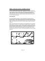
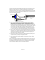
BUILDING AN ANTENNA (for your WSR-1 weather satellite receiver)
We will show you the dimensions and the connections required as well as the
materials we used to make a turnstile antenna, but if more information is
needed, we advise you to look into an ARRL handbook, or one of the many
antenna books out on the market.
Look at Fig A, the antenna wiring diagram. You'll notice that there are two
different types of coaxial cable involved. You must use the coax specified to
ensure proper phasing of the crossed dipoles.
Weather satellite transmissions are transmitted circularly polarized, meaning
the signals can be more easily received with antennas that are also circularly
polarized. When a signal is circularly polarized, it can be either right hand
polarized or left hand polarized. In the case of weather satellites, you will want
your antenna to be right hand polarized to receive the signal well. Wire your
antenna as shown in the diagram, and it will be right hand polarized. If you
mess up, it it easy to fix. You can either flip the antenna upside down, or
reverse the connections on any two opposing elements. For more information
and theory on polarized signals, you can consult a ARRL handbook or antenna
book.
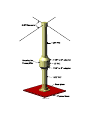
The four elements of our antenna will work best if they are on the same plane,
in other words, in the shape of a right angled X. You can make the elements
out of thin threaded stock found at the hardware store, stiff metal wire, or brass
or copper tubing. You can mount your elements onto a piece of circuit board or
fabricated holder that insulates the four elements from each other. Then mount
this into a piece of PVC pipe to use as a stand. Make a base for the other end
of the PVC using an end cap and some plywood. See the diagram for ideas.
You can also enhance this antenna design with a little ingenuity and silicon
sealant to make it weatherproof. If you wish, you can leave a center portion of
the mast unglued to allow you to repair or replace the preamp inside the pipe at
a later time.
If you have trouble receiving a satellite when one comes over, try flipping the
elements over to reverse the polarization. Otherwise check your cable lengths
and element lengths. They need to be fairly close to what we show you for best
reception.
WSR-1A• 28
13.13 in
TURNSTILE WIRING DIAGRAM
13.13 in
13.13 in
13.13 in
Fig A
(CLOSE UP)
Fig B
WSR-1A• 29
WSR-1A• 30
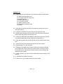
PREAMP INSTALLATION
This part assumes that you have completely assembled your preamp that came
with this kit. This preamp operates off of the power from your weather satellite
receiver through the antenna cable of your radio, so care has to be taken so
that you don’t short out any connections. Installation of the preamp is fairly
simple, yet there are a few considerations you will wish to look into before you
continue.
Any RF preamp should be located as close as possible to the antenna itself for
best performance. This is due to the losses involved in the cabling to the
antenna. Since a signal can be very weak at the antenna, it can be almost
nonexistent after it has gone through a length of cable. A non existent signal
doesn’t get amplified very well. If you boost the weak signal near the antenna, it
can be boosted to a high enough level that it can easily be sent down the length
of the cable.
THE WSR-LNA
<-- To Antenna
To WSR-1 -->
Hookup is simple if you are using coax cable such as RG-58 or better 50 ohm
cable. Just run a piece from your WSR-1 to the jack marked RCVR (J3) on the
WSR-LNA, and then another piece from the holes marked J1 or J2 or both
depending on the number of antenna elements. For the turnstile antenna just
use one of the holes. The center lead goes in these holes, and the outside
braid is soldered to the adjacent holes on the ground plain. The DC power is
transferred only to J3, so if you accidentally hook it up backwards, it just won’t
work at all. Make sure when you’re finished making connections to check for
12VDC on J3. If not there may be a break or poor connection in your cable
system.
Turn on your receiver when there is a satellite coming overhead (this is where
satellite predicting software comes in really handy). You should be able to pick
it up with little difficulty, especially after it climbs more that 10 degrees over the
horizon. If you are not receiving anything yet, wait until the satellite passes the
45 degree mark before jumping to conclusions. Some satellites are tougher
than others to receive. If you are still having troubles, first test for the twelve
volts present on the preamp, then check your antenna for proper polarization. If
both are correct, you may need to check your preamp for proper assembly, or
even possibly your WSR-1A. Consult the assembly instructions for some help
on these matters.
WSR-1A• 31
HOW TO RECEIVE A TRANSMISSION
The easiest way to receive a transmission is to know when one is coming, and
what format it will be in. There are several different satellite formats out there,
but the most common and useful is NOAA. For now we will describe how to get
NOAA transmissions and display them on a PC. Other satellites will follow as
you gain more insight into what is going on.
Every NOAA satellite seems to have a personality of its own, and there are
several of them floating around in outer space having a little party. All but the
newest satellites show up in the morning, and then again in the evening. The
newer satellites show up during odd times in the day. Some satellites come in
very strongly, others are weak. The newest NOAA satellite is so strong that it is
possible to pick it up right on the horizon!
There are a few programs available on bulletin boards that will allow you to
track various satellites and even show you the receivable area that they are
transmitting to. It is strongly recommended that you download one of these
programs because it makes life much easier. One of the best ones we have
found is called TRAKSAT. You can use this program to pin-point exactly where
satellites are, and when they will pass overhead, to name a few features.
Paul E. Traufler
111 Emerald Drive
Harvest, AL. 35749
(205)-726-5511 (Work)
(205)-830-8450 (Home)
Latest Updates, program, info, and Kepler Elements
R.P.V. Bulletin board (California)
Modem Settings: 9600,8,N,1
(310) 741-7299
CREDITS:
Thanks to Bill Schwittek, for information on the MultiFAX system and general
weather satellite information used in this manual.
MultiFAX
Route 1, Box 27
Peachland, NC 28133
PHONE (704) 272-9028
FAX (704) 272-9036
BBS (716) 425-8759
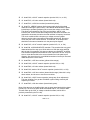
WSR-1A• 32
page 17, step110
page 22, step 140
WSR-1A• 33
SPECIFICATIONS
Sensitivity ...................................................... 1uV or -107dBm without preamp
-122dBm with preamp (15 dB
gain)
Outputs ......................................................... 1 adjusted speaker output
1 set line level output
1 tape recorder control output
Power ............................................................ 12VDC @ .20A
Filtering, input ............................................... Two section helical filter
Filtering, first IF ............................................. 150kHz wide, 10.7Mhz ceramic
Filtering, next IF ............................................ 15kHz wide, 450kHz ceramic
Filtering, Preamp .......................................... Two section helical
Stability ......................................................... 1ppm from 10ºC to 50ºC
Maximum resolution ...................................... Down to 2 Miles
Receivable
Frequencies:
CHANNEL FREQUENCY
1
136.77MHz
2
137.13MHz
3
137.30MHz
4
137.40MHz
5
137.50MHz
6
137.62MHz
7
137.77MHz
8
137.85MHz
FOR MORE INFORMATION
Taggart, Ralph E. Weather Satellite Handbook. 4th edition. American Radio
Relay League, 1990.
Dallas Remote Imaging Group (DRIG), PO Box 117088 Carrollton, TX 75011.
Building a Weather Satellite Ground Station: A Primer, Apr, 1992.
ARRL Handbook. American Radio Relay League, 225 Main St., Newington, CT
06111. Annual publications are available.
Dallas Remote Imaging Group (DRIG) Bulletin Board; (214) 394-7438
Dedicated to satellite imaging
R.P.V. Bulletin board (California) 9600,8,N,1 (310) 741-7299
Home of latest TRAKSAT software and Kepler elements
WSR-1A• 34
WSR-1A• 35
WSR-1A• 36
The Ramsey Kit Warranty
Please read carefully BEFORE calling or writing in about your kit. Most problems can be solved
without contacting the factory.
Notice that this is not a "fine print" warranty. We want you to understand your rights and ours too! All
Ramsey kits will work if assembled properly. The very fact that your kit includes this new manual is your
assurance that a team of knowledgeable people have field-tested several "copies" of this kit straight
from the Ramsey inventory. If you need help, please read through your manual carefully. All information
required to properly build and test your kit is contained within the pages!
1. DEFECTIVE PARTS: It's always easy to blame a part for a problem in your kit, Before you conclude
that a part may be bad, thoroughly check your work. Today's semiconductors and passive components
have reached incredibly high reliability levels, and it’s sad to say that our human construction skills have
not! But on rare occasions a sour component can slip through. All our kit parts carry the Ramsey
Electronics Warranty that they are free from defects for a full ninety (90) days from the date of
purchase. Defective parts will be replaced promptly at our expense. If you suspect any part to be
defective, please mail it to our factory for testing and replacement. Please send only the defective part
(s), not the entire kit. The part(s) MUST be returned to us in suitable condition for testing. Please be
aware that testing can usually determine if the part was truly defective or damaged by assembly or
usage. Don't be afraid of telling us that you 'blew-it', we're all human and in most cases, replacement
parts are very reasonably priced.
2. MISSING PARTS: Before assuming a part value is incorrect, check the parts listing carefully to see if
it is a critical value such as a specific coil or IC, or whether a RANGE of values is suitable (such as "100
to 500 uF"). Often times, common sense will solve a mysterious missing part problem. If you're missing
five 10K ohm resistors and received five extra 1K resistors, you can pretty much be assured that the '1K
ohm' resistors are actually the 'missing' 10 K parts ("Hum-m-m, I guess the 'red' band really does look
orange!") Ramsey Electronics project kits are packed with pride in the USA. If you believe we packed
an incorrect part or omitted a part clearly indicated in your assembly manual as supplied with the basic
kit by Ramsey, please write or call us with information on the part you need and proof of kit purchase.
3. FACTORY REPAIR OF ASSEMBLED KITS:
To qualify for Ramsey Electronics factory repair, kits MUST:
1. NOT be assembled with acid core solder or flux.
2. NOT be modified in any manner.
3. BE returned in fully-assembled form, not partially assembled.
4. BE accompanied by the proper repair fee. No repair will be undertaken until we have received the
MINIMUM repair fee (1 hour labor) of $36.00, or authorization to charge it to your credit card
account.
5. INCLUDE a description of the problem and legible return address. DO NOT send a separate letter;
include all correspondence with the unit. Please do not include your own hardware such as
non-Ramsey cabinets, knobs, cables, external battery packs and the like. Ramsey Electronics,
Inc., reserves the right to refuse repair on ANY item in which we find excessive problems or
damage due to construction methods. To assist customers in such situations, Ramsey
Electronics, Inc., reserves the right to solve their needs on a case-by-case basis.
The repair is $36.00 per hour, regardless of the cost of the kit. Please understand that our technicians
are not volunteers and that set-up, testing, diagnosis, repair and repacking and paperwork can take
nearly an hour of paid employee time on even a simple kit. Of course, if we find that defective in
manufacture, there will be no charge to repair your kit (But please realize that our technicians know the
difference between a defective part and parts burned out or damaged through improper use or
assembly).
4. REFUNDS: You are given ten (10) days to examine our products. If you are not satisfied, you may
return your unassembled kit with all the parts and instructions and proof of purchase to the factory for a
full refund. The return package should be packed securely. Insurance is recommended. Please do not
cause needless delays, read all information carefully.
WSR-1A• 37
WSR-1A Weather Satellite Receiver
Quick Reference Page Guide
Introduction to the WSR-1A ...................
Parts list .................................................
Circuit Description ..................................
Construction ..........................................
Schematic ..............................................
Initial Testing .........................................
Trouble Shooting ...................................
Antennas ...............................................
Building an Antenna ...............................
Preamp ..................................................
Parts Layout ..........................................
Specifications ........................................
4
6
9
11
20
25
27
28
30
33
35
36
REQUIRED TOOLS
• Soldering Iron Ramsey #RTS06, (Radio Shack #RS64-2072)
• Thin Rosin Core Solder Ramsey #RTS12, (RS64-025)
• Needle Nose Pliers Ramsey #RTS05, (RS64-1844)
• Small Diagonal Cutters Ramsey #RTS04, (RS64-1845)
<OR> Complete Soldering Tool Set (RS64-2801)
ADDITIONAL SUGGESTED ITEMS
Soldering Iron Holder/Cleaner (RS64-2078)
Holder for PC Board/Parts Ramsey #RTS13, (RS64-2094)
•
•
TOTAL SOLDER POINTS
430
Price: $5.00
Ramsey Publication No. MWSR-1A
Assembly and Instruction manual for:
RAMSEY MODEL NO. WSR-1A
RAMSEY ELECTRONICS, INC.
793 Canning Parkway
Victor, New York 14564
Phone (716) 924-4560
Fax (716) 924-4555
ESTIMATED ASSEMBLY
TIME
Beginner ...............11.3 hrs
Intermediate .........7.3 hrs
Advanced .............5.3 hrs
Printed on recycled
WSR-1A• 38