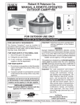
1
OWNER’S
MANUAL
05 Series Shown
OCBE-44 series
ROUND OUTDOOR CAMPFYRE CONTROL SYSTEM
INSTALLER & CONSUMER: These instructions MUST
be retained with this appliance for future reference.
WARNING: If the information in this manual
is not followed exactly, a fire or explosion
may result causing property damage,
personal injury or loss of life.
Important: Read these instructions carefully
before starting installation of the unit.
WARNING
Improper installation, adjustment, alteration,
service, or maintenance can cause property
damage, personal injury, or loss of life. Read
the installation, operating and maintenance
instructions thoroughly before installing or
servicing this equipment.
- Do not store or use gasoline or other
flammable vapors and liquids in the
vicinity of this or any other appliance.
WHAT TO DO IF YOU SMELL GAS:
• Do not try to light any appliance.
• Do not touch any electrical switch; do not
us any phone in your building.
• Immediately call your gas supplier from
a neighbor's phone. Follow the gas
supplier's instructions.
• If you cannot reach your gas supplier, call
the fire department.
This appliance is designed as an attended
appliance. Adults must be present when the
unit is operating. DO NOT leave this unit burning
when unattended. If this product is left burning
unattended, it may cause damage or serious injury.
CODE AND SUPPLY REQUIREMENTS:
This outdoor campfire kit must be installed in
accordance with local codes and ordinances,
or, in the absence of local codes, with the latest
National Fuel Gas Code, ANSI Z223.1.
Installation and service must be performed
by an NFI Certified or other qualified
professional installer, service agency, or
gas supplier.
WARNING: For Outdoor Use Only
ROBERT H. PETERSON CO. • 14724 East Proctor Avenue • City of Industry, CA 91746
REV 5 - 1209220850
1
L-A2-248
TABLE OF CONTENTS
3
4
5
5
6
6
6
7
8
8
8
8
9
10
11
11
13
15
16
17
18
19
19
20
PARTS LIST
PRE-INSTALLATION AND PREPARATION SAFETY GUIDELINES
INSTALLATION SAFETY GUIDELINES
OPERATING THE UNIT SAFELY AND CORRECTLY
IMPORTANT SAFETY INFORMATION
MINIMUM CLEARANCE TO COMBUSTIBLES
INSTALLATION
INSTALLATION SPECIFICATIONS
CONNECT TO THE GAS SUPPLY
CONNECT TO A POWER SUPPLY (05 Series Only)
LEAK TEST
CONTROL PANEL INTERIOR ACCESS (IF APPLICABLE)
INSTALLING/REPLACING BATTERIES (IF APPLICABLE)
CONVERTING TO A DIFFERENT GAS TYPE (PIEZO LIT)
DECORATIVE MEDIA OPTIONS
OPTIONAL CAMPFYRE LOGS
OPTIONAL BEACHWOOD LOGS AND/OR VOLCANIC STONE
OPTIONAL GLASS/GEMS OR RIVER ROCK ON GLASS/GEMS
MANUAL (PIEZO) LIGHTING INSTRUCTIONS
05 VALVE SERIES LIGHTING INSTRUCTIONS
NOTES PAGE
OPERATION
CLEANING & MAINTENANCE
PETERSON CAMPFYRE LIMITED WARRANTY
REV 5 - 1209220850
2
L-A2-248
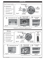
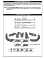
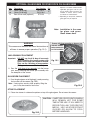
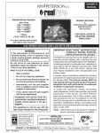
PARTS LIST
Piezo lit manual series
Flex connector
3
NO. DESCRIPTION
1
Burner pan
assembly
2
1. Burner pan assy
Control
panel
assembly
2. Control panel assembly
3. Flex connector (2)
Burner
rings
4. Ignitor assy
5. Lava granules (10 lbs)
& lava coals (6 lbs)
2
Ignitor
assembly
under screen
Fig. 3-1
Ignitor assembly
(under screen)
4
Control panel front view
Fig. 3-2
5
Fig. 3-3
Lava granules
& coals
Fig. 3-4
Contact your local dealer for replacement parts
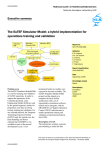
05 Series
NO. DESCRIPTION
1. Burner pan assy
2. Control panel assembly
3. Flex connector (2)
4. Remote handset
5.
Flex connector
3
6. Lava granules (10 lbs)
& lava coals (6 lbs)
2
Remote
handset
2
Control
panel
assembly
Pilot assembly
Fig. 3-5
Control panel front view
4
Burner rings
Pilot
assembly
under screen
1
Burner pan
assembly
Pilot assembly
(under screen)
5
6
Fig. 3-6
Lava granules
& coals
Pilot hood
Fig. 3-3
REV 5 - 1209220850
Control system
Flame
sensor and
Ignitor electrode electrode
Fig. 3-4
3
Fig. 3-5
L-A2-248
PRE-INSTALLATION AND PREPARATION SAFETY GUIDELINES
A. Before installing this unit, check the MINIMUM CLEARANCE TO COMBUSTIBLES section to ensure that
the surrounding area is properly sized for the installation.
B. The unit is for outdoor use only. DO NOT install or use this appliance inside a building, garage, or any
other enclosed area, including recreational vehicles and/or boats. This unit must be installed in such
a manner that the vent opening at the base of the unit remains clear and free of all obstructions
at all times and during all weather conditions.
C. CHECK GAS TYPE (natural gas or propane): The gas supply you intend to use may not be the same as
that stated on the unit rating plate as purchased. If the gas supply is different, convert the unit to the
gas type you intend to use. See the CONVERTING TO A DIFFERENT GAS TYPE SECTION. If you
are unsure, contact the dealer for assistance. ONLY PIEZO LIT MANUAL UNITS ARE CONVERTIBLE.
D. FOR NATURAL GAS: The minimum inlet gas-supply pressure for purposes of input adjustment is 5" water
column (w.c.), and the maximum inlet gas-supply pressure is 10.5 " w.c. FOR PROPANE: The minimum
inlet gas-supply pressure for purposes of input adjustment is 8" w.c., and the maximum inlet gas-supply
pressure is 13" w.c. DO NOT INSTALL THIS UNIT IF MINIMUM PRESSURE IS NOT AVAILABLE OR
IF MAXIMUM PRESSURE IS EXCEEDED.
E. Gas piping system must be sized to provide minimum inlet pressure at the maximum flow rate (BTU/hr).
Undue pressure loss will occur if the pipe is too small, or the run is too long.
F. For installations at elevations above 2,000 ft., contact your local dealer or gas supplier before installing.
Input ratings should be reduced approximately 4% for each 1,000 ft. above sea level. Refer to the National
Fuel Gas Code.
G. The unit and its individual shutoff valve must be disconnected from the gas-supply piping system during
any pressure testing of that system at test pressures in excess of 1/2 psi (3.5 kPa). This is accomplished
by closing the gas-supply line valve. The unit must be isolated from the gas-supply piping system by
closing its individual manual shutoff valve during any pressure testing of the gas-supply piping system at
test pressures equal to or less than 1/2 psi (3.5 kPa).
H. INSTALLER NOTE: This unit should be installed so that it can be removed if service is required.
I. GAS-SUPPLY PLUMBING REQUIREMENTS
Apply only joint compounds that are resistant to all gasses on all male pipe fittings. Make sure to tighten
every joint securely. Do not use pipe joint compound to connect flare fittings. Bring the gas-supply pipe
up from beneath the enclosure near its center (if applicable).
CAUTION:
Installation and maintenance must be done by an NFI Certified or other qualified professional
installer. Installer, read these instructions before installing this product. Be sure you understand
all safety precautions and warnings contained in this manual.
Note: An external on/off valve in the gas line is required for safety when the unit is not in use. It also
provides for convenient maintenance and repair.
4
INSTALLATION SAFETY GUIDELINES
A. Installation and repair should be done by a qualified service person. The appliance should be inspected
before use and at least annually by a qualified service person. More frequent cleaning may be required
as necessary. It is imperative that control compartment, burners and circulating air passageways of the
appliance be kept clean.
B. Carefully inspect for shipping damage. If any parts are damaged, call the dealer.
C. Correct installation and proper placement of the unit and decorative media is crucial to the safe performance
of the unit. See installation instructions for further information. NEVER COVER THE BURNER SCREEN
WITH DECORATIVE MEDIA OR ANY OTHER ITEM. THIS WILL IMPAIR ITS EFFICIENCY AND CAUSE
THE UNIT TO MALFUNCTION.
D. Ensure that the unit is installed in such a manner that the vent opening at the base of the unit remains
obstacle-free at all times and during all weather conditions.
E. Due to high temperatures, the unit must be located out of traffic areas and away from combustibles.
OPERATING THE UNIT SAFELY AND CORRECTLY
A. This appliance is only intented for operation in temperatures above 32°F.
B. When shutting the unit down—be sure to TURN THE CONTROL VALVE FULLY OFF.
C. Children MUST be carefully supervised when they are in the area of this appliance.
D. DO NOT sit or place any part of the body, clothing, or other flammable materials on or near the unit
surround. Children and adults should be alerted to the hazard of high surface temperatures and should
stay away to avoid burns or clothing ignition.
E. Every time you use the unit, make sure that:
1. The area around the unit is clear and free from combustible materials, gasoline and other flammable
vapors and liquids.
2. There is no blockage of the airflow through the vent openings located on the bottom of the unit.
3. THE SCREEN IS NOT COVERED OR BLOCKED WITH DECORATIVE MEDIA OR ANY OTHER ITEM.
F. WARNING: HOT WHILE IN OPERATION AND FOLLOWING OPERATION. Serious injury can occur!
DO NOT throw trash, paper, or other flammable materials onto the unit. DO NOT leave in operation when
unattended.
WARNING: DO NOT operate this unit in the rain.
G. SOLID FUEL MUST NOT BE BURNED in the unit.
H. DO NOT continue using if you smell unusual odors, or have headaches, nausea, or dizziness.
I. DO NOT store any combustible materials, gasoline, and any other flammable vapors/liquids in the vicinity
of the unit. Provide adequate clearance for servicing and operation.
J. Matches, paper, garbage, or any other material must not be thrown onto the unit or into the flame.
K. DO NOT use the unit if any part of it has been underwater. Immediately call a qualified professional service
technician to inspect the set and to replace any part of the control system that has been underwater.
5
IMPORTANT SAFETY INFORMATION
BE CAREFUL
If not installed and used correctly per these instructions,
this product can cause serious injury.
CAUTION:
Installation and maintenance must be done by an NFI Certified or other qualified professional
installer. Read these instructions before installing this unit. Be sure you understand all safety
precautions and warnings contained in this manual.
A. FOR OUTDOOR USE ONLY.
B. When shutting the unit down—be sure to TURN THE CONTROL VALVE FULLY OFF.
C. WARNING: CARBON MONOXIDE POISONING MAY LEAD TO DEATH. DO NOT MODIFY THIS unit OR
ITS CONTROLS, EXCEPT AS PROVIDED FOR IN THIS MANUAL. Any other change may be dangerous.
Improper installation or use of the unit can cause serious injury or death from fire, burns, explosions, or
carbon monoxide poisoning.
D. Check state and local codes to determine if the unit is permitted in your locality before installation.
E. The manual valve allows adjustable flame height and heat output. THESE SETTINGS MUST ALWAYS
BE HIGH ENOUGH FOR THE FLAME TO BE CLEARLY VISIBLE.
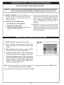
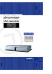
MINIMUM CLEARANCE TO COMBUSTIBLES
Fig. 6-1
Note:
(control panel
model shown)
Clearances to Combustible Construction:
Nothing should be above
the unit.
Side walls: 36" from each side of the enclosure.
Ceiling: Nothing should be above the unit.
Flooring: 0" - Can be installed on deck, slab, floor, etc.
36"
Clearance
36"
Clearance
From sides to
any combustible
construction
From sides to
any combustible
construction
Keep vent openings clear at all times for proper venting.
The dimensions shown in Fig. 6-1 are MINIMUM
CLEARANCES to maintain when you install this
unit. ALL SIDES of the enclosure opening MUST
BE AT LEAST 36" from any combustible side walls.
The unit MUST NOT BE installed under any type
of ceiling or overhang.
INSTALLATION
Important: Be sure you have read and understand all safety precautions and warnings contained in this
manual.
BEFORE PROCEEDING, CAREFULLY READ ALL OF THE IMPORTANT SAFETY INFORMATION
CONTAINED IN THIS OWNER’S MANUAL, INCLUDING:
A. IMPORTANT SAFETY INFORMATION.
B. INSTALLATION SAFETY GUIDELINES.
C. MINIMUM CLEARANCE TO COMBUSTIBLES.
BE SURE THE GAS SUPPLY FOR THE UNIT IS TURNED OFF.
Note: When installing the unit to natural gas or household propane, you must have a gas-supply line that
has been installed by a qualified professional technician in accordance with all local codes. Refer
to the PARTS LIST when installing the unit.
6
INSTALLATION (Cont.)
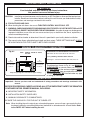
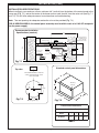
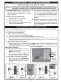
INSTALLATION SPECIFICATIONS
When installing in your enclosure, allow a minimum of 8" (vertical) from the bottom of the control panel to the
burner pan (Fig. 7-1), and set the center of the burner pan no more than 30" from the outer wall (see Fig. 7-1
and 7-2). This will allow adequate access for maintenance and troubleshooting.
Note: Two vent openings for adequate combustion air must be provided (Fig. 7-1).
FOR 05 SERIES MODELS; the control panel assembly must be within reach of a 110V GFI receptacle
(for the power supply).
Recommended Installation
Specifications (nominal)
3 - 5"
min
30"
max
Burner pan assy
Flex
connector
Center hole
for burner
Sub-plate
12"
min
Allow for draining
by drillling 4 holes
across sub-plate
(max. 1/8" in dia.)
8"
min
(to valve)
10 sq. in. (min.)
vent opening
2 required
05 series
burners
require a
110V GFI
receptacle
Flex
connector
Control
panel
assy
(from valve)
Gas supply
Power Supply
(05 series only)
Fig. 7-1
Standard control panel dimensions
Top view
The maximum distance from the
center of the burner pan, to the
outer wall, is 30".
A
Mounting
holes (4)
B
28"
dia.
18 3/8"
C
Fig. 7-2
D
18 3/8"
Fig. 7-3
Mounting holes (4)
Control Panel
Panel Dimensions
Dimensions
Control
A
A
B
B
C
C
D
D
Piezo Lit
Lit Manual
Manual 9-33/ " 5-33/ " 8-11/ " 8-55/ "
Piezo
9- /44" 5- /88" 8- /22" 8- /88"
Series
Series
05 Series
Series
01
7-17//28"" 55-33//88"" 88-11//22"" 76-37//88""
5-
05 Series
7-7/8" 5Table
13/8"
Table 1
7
8-1/2" 6-7/8"
INSTALLATION (Cont.)
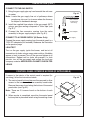
CONNECT TO THE GAS SUPPLY
1. Bring the gas-supply pipe up from beneath the unit near
its center.
Note: Locate the gas supply line out of pathways where
people may trip over it or in areas where the line may
be subject to accidental damage.
2. Install the supplied flare adaptor to the gas supply (NPT)
using a gas pipe sealing compound or Teflon tape (see
Fig. 8-1).
3. Connect the flex connector coming from the valve
assembly to the gas supply adaptor (see Fig. 8-1).
CONNECT TO A POWER SUPPLY (05 Series Only)
Fig. 8-1
Flex connector
(coming from
valve assy)
Flare adaptor
Gas supply
Connect the power supply coming from the control panel to a
110V GFI receptacle (not included). Reference the illustration
on the previous page.
LEAK TEST
Turn on the gas supply, ignite the burner, and test at all
connections for leaks using a soapy water solution. If bubbles
appear, a leak is present. Turn off the gas and tighten at all
connections. Repeat until no leaks are present. If a leak
persists, turn off the gas supply and contact the local gas
company or dealer. NEVER USE A FLAME TO CHECK FOR
LEAKS.
CONTROL PANEL INTERIOR ACCESS (IF APPLICABLE)
If access to the interior of the control panel is required (for
servicing), follow the instructions below:
1. The control panel bottom plate must be removed to allow
access to the transformer / valve assembly found inside.
Remove the screws found along the bottom of the control
panel sides (see Fig.8-2).
Note: There are 2-3 screws found on the bottom of each
side.
2. When service is completed, reposition the control panel
bottom plate in place and fasten using the existing screw.
8
Fig. 8-2
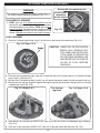
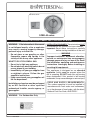
INSTALLING/REPLACING BATTERIES (IF APPLICABLE)
CAUTION: ENSURE THE UNIT IS CONNECTED
TO THE GAS LINE AND HAS BEEN
TESTED FOR LEAKS BEFORE YOU
INSERT BATTERIES.
I N S TA L L I N G / R E P L AC I N G T H E S PA R K
GENERATOR BATTERY FOR PIEZO LIT MANUAL
UNITS
To access the "AA" battery, unscrew the complete
generator cap (Fig. 9-1). Withdraw the existing battery
and spring (Fig. 9-2) and detach the "AA" battery.
Insert the new battery (negative end first) into the
spring. Insert the battery and spring into the generator
and replace the cap, screwing down until snug. Do
not overtighten.
Fig. 9-1
Fig. 9-2
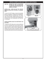
INSTALLING/REPLACING THE BATTERIES FOR
05 SERIES
To access the "AA" battery pack, unscrew and remove
the two (2) retaining screws on the control system.
Pull out the control system and then slide open the
battery pack lid as shown in Fig. 9-3. Replace the old
batteries with four (4) new "AA" batteries. Resecure
the battery pack lid and return the control system into
the control panel. Screw in the two (2) retaining screws.
Fig. 9-3
"AA" Battery pack exposed
INSTALLING/REPLACING THE BATTERIES FOR
01 SERIES
To access the "D" battery pack, unscrew the access
plate on the left side of the control panel. Only unscrew
the large retaining screw. Grip the top half of the
access plate and pull it out to expose the "D" battery
pack (Fig. 9-4). Replace the old batteries with two
(2) new "D" batteries. Return the access plate into
the control panel. Screw in the large retaining screw.
To access the "AA" battery pack, unscrew and remove
the two (2) retaining screws on the control system.
Pull out the control system and then slide open the
battery pack lid as shown in Fig. 9-5. Replace the old
batteries with four (4) new "AA" batteries. Resecure
the battery pack lid and return the control system into
the control panel. Screw in the two (2) retaining screws.
Fig. 9-4
"D" Battery pack exposed
Fig. 9-5
"AA" Battery pack exposed
9
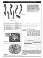
CONVERTING TO A DIFFERENT GAS TYPE (PIEZO LIT)
To convert PIEZO LIT MANUAL UNITS (only) from propane to natural gas or from natural to propane gas, carefully
follow the steps below:
1. SHUT OFF THE GAS SUPPLY TO THE UNIT AND ANY NEARBY ELECTRICAL SOURCES OR APPLIANCES.
2. If present, remove all decorative media from the unit.
3. If installed, remove the screws attaching the burner pan to your enclosure.
4. The control panel bottom plate must be removed to allow access to the valve assembly found inside. Remove the
screws found along the bottom of the control panel sides. (There are 2-3 screws found on the bottom of each side.)
5. Detach the thermocouple (taking care not to kink it) from the safety valve (see Fig. 10-2 for location). Detach the
ignitor wire from the piezo igniter (see Fig.10-3 for location).
6. Carefully detach the flex connector attached to the orifice holder (found on the end of the burner pipe, see Fig. 10-4),
6. Carefully
detach
flex
attached
to the
fuel(see
injector
air mixer (see Fig. 10-4) and unscrew the air mixer
Fig. or
10-5).
then unscrew
thethe
orifi
ceconnector
holder from
the burner
pipe
from the burner pipe.
7. Replace the fuel injector/air mixer with the proper air mixer/fuel injector for your requirement
Note:
you arethe
converting
andthe
using
you
MUST
install
thenow
air be
shutter
over
andIfreattach
connectortofrom
valve natural
(see Fig.gas
10-4).
The
regulator
must
converted
burner
pipe
to
cover
the
air
holes
(see
Fig.
10-5).
For
propane
(L.P.)
gas,
remove
the
air
to the new gas type.
shutter.
Read gas
type here
Replace the orifice holder and reattach the flex connector (coming from the valve, see Fig.
10-4). The regulator must now be converted to the new gas type.
(Showing propane)
8. The regulator is situated after the valve (see Fig. 10-2), inside the control panel. To convert
the regulator to the required gas type:
a) Unscrew and remove the cap (see Fig. 10-1) from the regulator, extracting the converter.
Note:
If necessary, carefully rotate the regulator to access the cap.
Regulator stalk removed
b) Remove the converter (the red plastic stalk, Fig. 10-1) by carefully pulling it away from
the center of the cap (it will snap out of its seating).
Fig. 10-1
c) Turn the converter around and replace carefully into the center of the cap (it will snap into place). Check that
you can read the type of gas the unit is set for.
Note:
EACH END OF THE PLASTIC CONVERTER IS EMBOSSED WITH EITHER THE LETTERS “NAT” OR “L.P.”
FOR THE RESPECTIVE GAS TYPE ("NAT." for natural - "L.P." for propane). WHEN THE CONVERTER
IS IN THE CAP AND THE CAP IS HELD UPPERMOST, THE LETTERS SEEN (AT THE BOTTOM OF THE
STALK) INDICATE THE GAS THAT THE REGULATOR IS SET UP FOR. (Fig. 10-1 shows the converter set
for propane gas.)
d) Replace the cap and converter into the regulator and screw down until snug.
9. Once the above steps are complete, reattach the thermocouple and ignitor wires. Reinstall the control panel bottom
plate.
10. Restore your gas supply and check for leaks per the INSTALLATION section. When no leaks are detected, fasten
the burner pan back into place on the enclosure and replace the decorative media.
Fig. 10-2
Valve
Thermocouple
wire
(Detach this when
changing gas type.
Reattach before use.)
Do not overtighten.
Ignitor module (interior view)
(Manual unit only)
Ignitor wire
(Detach when changing orifice
for different gas type. Replace
before use.)
Regulator
(Remove cap to convert
when changing gas type.
Replace before use.)
(Manual unit only)
Valve shown out of
control box for clarity
Fig. 10-3
Connector from valve attached to fuel injector/air
mixer on burner pipe
Fig.
Fig.10-5
10-4
Connector from valve attached to orifice holder
on burner pipe
Burner
pipe
Fig. 10-4
Orifice holder
Fuel
injector
Air shutter (Used only with
Detach connector from fuel injector/airnatural
mixer and
withfor
gas.replace
Removed
air mixer/fuel injector when changing to apropane
differentgas.)
gas.
Detach connector from orifice holder when
changing orifice to a different gas type.
10
DECORATIVE MEDIA OPTIONS
The unit has several options for decorative media, each with a different set of components and setup instructions.
These setup instructions are for your reference. None of these options come with the outdoor campfyre kit
and must be ordered separately.
Note: Lava media (included with burner) is always placed on the burner first in each option. This provides
an important base for the diffusion of gas and air. Depending on fire-pit size, more lava than supplied
may be required.
OPTIONAL CAMPFYRE LOGS
OCL-34
Item
1.
2.
3.
4.
5.
6.
7.
5
Part #
OCL-8YC
OCL-15BC
OCL-12T
OCL-13T
HRDL-12T
RDL-7T
WC-6
Description
“Y” center support log
Curved bottom log
12" top log with knothole
13" top log with knothole
12" top log
8" top log
Wood chips (6 pcs.)
Qty
1
2
1
1
2
4
1
4
3
1
2
5
2
6
Note: Photos NOT to scale.
7
11
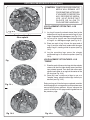
OPTIONAL CAMPFYRE LOGS (cont.)
Screen with lava on burner pan
WARNING
This screen must be clear and free of obstructions at
all times to ensure proper operation (Fig. 12-1).
DO NOT PLACE
LAVA MEDIA
ON THE SCREEN
LAVA MEDIA PLACEMENT
1. FIRST, pour the 10 lb bag of lava granules into the
burner pan, evenly covering the burner pan assembly
with the exception of the screen. THEN, pour the 6 lb
bag of lava coals into the burner pan, evenly covering
the burner pan assembly with the exception of the
screen. (Granules are smaller in size, coals are larger.)
Fig. 12-1
LOG PLACEMENT
1. Place the Y-shaped support log (Log #1) on the lava in the center of the enclosure (Fig.12-2).
Fig. 12-2 Steps 1 & 2
CAUTION: CAMPFYRE OR DECORATIVE
MEDIA WILL REMAIN HOT
FOR SOME TIME AFTER USE.
IF YOU NEED TO REPOSITION
ANY DECORATIVE MEDIA, USE
HEAT-RESISTANT GLOVES OR
ALLOW TO COOL BEFORE
HANDLING.
Scre
Screen
2
1
2
2. Place the two curved bottom logs (Logs #2) on opposite sides of the support log so as to keep the screen
clear (Log #1). (See Fig.12-2)
3. Rest the two (2) knothole top logs (Log #3, Log #4) against the center support log with one end in the lava.
4. Rest the next two top logs (Logs #5) against the support log with the other ends resting in the lava, forming
a teepee-type stack (Fig. 12-3).
The finished
log stack
Fig. 12-3 Steps 3 & 4
Fig. 12-4 Steps 5 & 6
4
3
5
5. Place the four (4) smallest logs (PARTS LIST, item #6) so they rest on the curved bottom logs as desired
(Fig. 12-4).
6. Place the six (6) wood chips (PARTS LIST, item #7) as desired around the log stack (Fig. 12-4).
12
OPTIONAL BEACHWOOD LOGS AND/OR VOLCANIC STONE
2
4
8
3
1
Fig. 13-1
5
7
6
OCBW-34
#
1.
2.
3.
4.
5.
6.
7.
8.
Description
Knotted log
Hooked log
Crooked log
Curved log
Stripped log
Long charred log
Short charred log
Volcanic stones (box)
Part Number
OCBWL-17
OCBWL-18
OCBWL-16
OCBWL-15
OCBWL-12
OCBWL-20
OCBWL-9
VS-25
Qty
1
1
1
1
1
1
1
1
Although log placement may vary, suggested log
placement for the Beachwood log set is provided below.
These log placements will allow for superior flame
pattern and appearance. Please read these instructions
completely and carefully before beginning.
LAVA AND STONE PLACEMENT
WARNING: Use only parts specifically approved
for use with this Real-Fyre® gas log
set. Failure to do so may result in
property damage or personal injury.
Check with your local Real-Fyre ®
dealer if you need more information.
Screen with lava on burner pan
DO NOT PLACE
LAVA MEDIA
ON THE SCREEN
1. FIRST, pour the 10 lb bag of lava granules into
the burner pan, evenly covering the burner pan
assembly with the exception of the screen. THEN,
pour the 6 lb bag of lava coals into the burner pan,
evenly covering the burner pan assembly with the
exception of the screen. (Granules are smaller in
size, coals are larger.)
Fig. 13-2
2. Pour the volcanic stones on top to fill the whole
burner pan.
With the ignitor screen clear of lava media and
volcanic stones distributed on top of the lava, nearly
any log placement is possible. It is also possible to
use only the Volcanic Stones and no logs at all.
2
Some general guidelines include always placing the
flat side of each log downward or inward and making
sure the logs are positioned so they are stable and
will not shift or roll. Logs must remain in the burner
pan when hot.
1
Fig. 13-3
13
OPTIONAL BEACHWOOD LOGS (cont.)
6
CAUTION: CAMPFYRE OR DECORATIVE
MEDIA WILL REMAIN HOT
FOR SOME TIME AFTER USE.
IF YOU NEED TO REPOSITION
ANY DECORATIVE MEDIA,
U S E H E AT- R E S I S TA N T
GLOVES OR ALLOW TO
COOL BEFORE HANDLING.
3
4
5
7
LOG PLACEMENT OPTION TWO - LOG
SQUARE
Fig. 14-1
1. Lay Log #1 across the volcanic stone, then lay the
hooked part of Log #2 over one end of Log #1 at an
angle of approximately 90 degrees (see Fig. 15-2).
Beachwood Log Set
p
Other options
2. Lay an end of Log #3 over the unattached end
of Log #2 at a 90-degree angle (see Fig. 14-2).
3
3. Place one end of Log #4 over the open end of
Log #3 and the other end underneath the open
end of Log #1, creating a kind of square (see Fig.
14-2).
2
4
4. Lay the remaining logs across the already
positioned logs in an attractive pattern (see Fig.
14-3).
1
LOG PLACEMENT OPTION THREE - LOG
"TEEPEE"
Fig. 14-2
1. Place the ends of three or four logs into the volcanic
stones with their flat sides facing inward and their
tops pointed upward. Then lean their other ends
against each other at an angle in the center of the
fire ring (see Fig. 14-4).
5
6
7
2. Once you have a stable set of logs to use as a
"teepee" frame, place the other logs similarly as
desired (see Fig. 14-5).
Enjoy your log set. After the logs are placed, consider
how changing their arrangement could produce even
more pleasing flame patterns. Always observe the
caution at the top of this page and the guidelines on
vious page.
the previous
Fig. 14-3
1
4
2
7
5
3
6
Fig
Fig. 14
14-4
4
Fig. 14-5
14
OPTIONAL GLASS/GEMS OR RIVER ROCK ON GLASS/GEMS
Item
1.
or
2.
Description
Glass (10 lb bag)
Gems (10 lb bag)
Box of river rock (optional)
Part Number
GL-10-x*
GLG-10-x*
STN-10
* Replace “x” in model number with the
applicable glass/gem code for your
chosen media. Glass and gems are
available in various colors; contact
your dealer for further details.
Qty
2**
1
** Depending on fire-pit size, additional
glass/gems may be required.
1
Note: Installation is the same
fo r g l a s s a n d g e m s .
Glass shown here.
2
Screen with lava granules on burner pan
WARNING
This screen must be clear and free of obstructions at
all times to ensure proper operation (Fig. 15-1).
DO NOT PLACE
LAVA GRANULES
ON THE SCREEN
LAVA GRANULE PLACEMENT
Important:
DO NOT use the 6 lb bag of lava coals
when installing this burner system with
glass. Set the lava coals aside or discard.
Only use the 10 lb bag of lava granules.
(The granules are smaller in size.)
Fig. 15-1
1. Pour the 10 lb bag of lava granules into the burner
pan, evenly covering the burner pan assembly with
the exception of the screen.
GLASS/GEM PLACEMENT
1. Pour the glass/gems out of the bag(s), evenly covering
the lava but not the screen (Fig. 15-2).
Note: If extra glass remains after properly filling the
pan, it may be stored for future use.
Fig. 15-2
STONE PLACEMENT
1. Place river stones in a decorative pattern on top of the glass/gems. Do not cover the screen.
Fig. 15-3
CAUTION: CAMPFYRE OR DECORATIVE MEDIA
WILL REMAIN HOT FOR SOME
TIME AFTER USE. IF YOU NEED TO
REPOSITION ANY DECORATIVE
M E D I A , U S E H E AT- R E S I S TA N T
GLOVES OR ALLOW TO COOL
BEFORE HANDLING.
15
OPERATING THE UNIT - LIGHTING AND EXTINGUISHING
FOR YOUR SAFETY, READ BEFORE LIGHTING
WARNING: IF YOU DO NOT FOLLOW THESE INSTRUCTIONS EXACTLY, A FIRE OR EXPLOSION MAY
RESULT, CAUSING PROPERTY DAMAGE, PERSONAL INJURY, OR LOSS OF LIFE.
A. BEFORE LIGHTING, smell all around the unit
area for gas. Be sure to smell next to the floor,
because some gas is heavier than air and will
settle on the floor.
B. WHAT TO DO IF YOU SMELL GAS
1. Shut off the gas to the appliance.
2. Extinguish any open flame.
3. If odor continues, immediately call your gas
supplier or the fire department.
C. Use only your hand to push in or turn the gas
control knob. Never use tools. If the knob will not
push in or turn by hand, DO NOT try to repair it.
Call a qualified professional service technician.
Force or attempted repair may result in fire or
explosion.
D. DO NOT use the unit if any part has been
underwater. Immediately call a qualified service
technician to inspect the unit and to replace any
part of the control system and any gas control that
has been underwater.
MANUAL (PIEZO) LIGHTING INSTRUCTIONS
1. STOP! Read the safety information above.
Fig. 16-1
2. Press and hold the electric ignitor button. The
ignitor will begin to spark with a rapid clicking
sound.
3. While holding the ignitor button in, push in the ON/
OFF control knob to open the gas valve.
4. Continue to hold the knob in for 10-15 seconds this
will allow the safety valve to engage, and the main
burner will ignite and remain lit. After releasing the
knob turn the ON/OFF control knob to adjust flame
height. If unit fails to light at step 4 after five (5)
seconds, STOP, turn control knob to OFF, wait 5
minutes, and repeat steps 2 & 3.
Note: If the burner will not stay lit after several tries, turn the gas control knob to OFF and call
your service technician or the gas supplier.
To turn the unit off, turn the ON/OFF valve fully to OFF.
16
OPERATING THE UNIT - LIGHTING AND EXTINGUISHING
FOR YOUR SAFETY, READ BEFORE LIGHTING
WARNING: IF YOU DO NOT FOLLOW THESE INSTRUCTIONS EXACTLY, A FIRE OR EXPLOSION
MAY RESULT, CAUSING PROPERTY DAMAGE, PERSONAL INJURY, OR LOSS OF LIFE.
C. Use only your hand to push in or move the
controls. Never use tools. If the control will not
push in or move by hand, DO NOT try to repair
it. Call a qualified professional service technician.
Force or attempted repair may result in fire or
explosion.
A. BEFORE LIGHTING, smell all around the unit
area for gas. Be sure to smell next to the floor,
because some gas is heavier than air and will
settle on the floor.
B. WHAT TO DO IF YOU SMELL GAS
1. Shut off the gas to the appliance.
D. DO NOT use the unit if any part has been
underwater. Immediately call a qualified service
technician to inspect the unit and to replace any
part of the control system and any gas control that
has been underwater.
2. Extinguish any open flame.
3. If odor continues, immediately call your gas
supplier or the fire department.
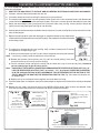
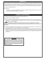
05 VALVE SERIES LIGHTING INSTRUCTIONS
Note: For any lighting method, no gas will flow to the main burner unless the pilot is lit and stable.
1. STOP! Read the safety information above.
2. Turn the gas valve to the ON position.
3. Lighting the unit using remote handset
a. Ensure the main switch is in the OFF/REMOTE position.
b. Slide the ON/REMOTE/OFF switch (O/R/O) to REMOTE setting (see Fig. 17-1).
c. Point the top of the remote handset toward the control panel and press the ON button on the handset. The valve
will begin its lighting sequence and the pilot will light. When the pilot flame becomes stable (about 10 seconds),
gas will flow to the main burner, and it will ignite.
4. Lighting the unit without using the remote
a. Slide the ON/REMOTE/OFF switch to the ON setting, OR, press the main switch to the ON position. The valve
will begin its lighting sequence and the pilot will light. When the pilot flame becomes stable (about 10 seconds),
gas will flow to the main burner, and it will ignite.
Fig. 17-1 control panel
SHUTTING OFF THE UNIT
5. Shutting off the unit using remote handset
a. Slide the ON/REMOTE/OFF switch (O/R/O) to
REMOTE position (center).
b. Point the top of the remote handset toward
the control panel and press the OFF button
(handset). Main burner and pilot will extinguish.
6. Shutting off the unit without using remote
a. With the main switch in the OFF/REMOTE
position; slide the ON/REMOTE/OFF switch
to the OFF setting. Main burner and pilot will
extinguish.
ON
ON
REMOTE
OFF
OFF/REMOTE
Fig. 17-1
Control
panel
main switch
OFF/REMOTE
ON
+
Set switch to REMOTE
& press ON (handset)
Fig. 17-2
O
R
+
O
R
Set to ON
Set to ON
Set switch to REMOTE &
press OFF (handset)
Fig. 17-3
Fig. 17-3
Fig. 17-4
17
O
R
+
Set to
OFF
Fig. 17-5
NOTES PAGE
Please use this page to record any information about your burner system that you may want to have at hand.
18
OPERATION
Each installation site for any unit presents its own unique combustion environment. Specific factors such as
weather, wind currents, yard debris, altitude, drafts, the size of the surrounding area, all have an influence
on the proper operation of the unit. A normally operating unit will demonstrate the following characteristics:
a) A lively, realistic yellow flame,
b) Odor-free.
• If the flame is not clean (identifiable by excessive sooting on the decorative media), refer to the
CLEANING AND MAINTENANCE section below.
CLEANING & MAINTENANCE
A. Always shut off the gas to the unit while performing service work.
B. Allow the unit to cool before servicing.
C. The unit should be inspected regularly. Excessive debris can build up on this unit from leaves, dirt, or
other debris. It is critical that all control components, burners, burner screen, and vent openings be kept
clean and free of all obstructions.
Keep the vent openings at the base of the enclosure clean and free of obstructions at all times.
Keep the screen on the burner pan clean and free of decorative media and other items that may cause
obstruction.
D. The burner assembly must be replaced prior to the unit being put into operation if it is evident that the
burner is damaged. Contact your local dealer for replacement parts.
E. Periodically perform visual checks of the burner flames, and pilot flames (if applicable). The burner flames
should be blue at the base with a combination of blue/yellow at the body and tips. The pilot (if applicable)
should be a steady flame, touching the electrode/thermocouple. Contact a qualified service person for
maintenance.
CAUTION
HOT DURING OPERATION AND AFTER USE.
Children must be supervised when in the vicinity of
this appliance. Serious injury may occur! Children
must be alerted to the hazard of high surface
temperatures and should stay away to avoid burns
or clothing ignition.
19
PETERSON CAMPFYRE LIMITED WARRANTY
THREE (3) YEAR LIMITED WARRANTY
All Peterson Outdoor Campfyre logs, enclosures, and burner component parts, (except valves and controls) are covered by a three
(3) year limited warranty.
All Peterson valves and controls are covered by a separate one (1) year limited warranty (excluding batteries).
PLEASE KEEP A COPY OF YOUR SALES SLIP FOR PROOF OF PURCHASE
This warranty applies to the original purchaser and to single family residential use only. It commences from date of purchase, and is valid only with
proof of purchase.
This warranty does not cover parts becoming defective through misuse, accidental damage, electrical damage, improper handling, lack of routine
maintenance, storage, and/or installation. Product must be installed (and gas must be connected) as specified in the instructions or operator’s
manual, by a qualified professional installer. Accessories, parts, valves, remotes, etc., when used must be Peterson Co. product.
This warranty does not apply to rust, corrosion, oxidation, or discoloration, unless the affected component becomes inoperable. It does not cover
labor or labor-related charges.
This warranty specifically excludes liability for indirect, incidental, or consequential damages. Some states do not allow the exclusion or limitation of
incidental or consequential damages, so the above exclusion may not apply to you. This warranty gives you specified legal rights, and you may have
other rights that may vary from state to state.
For additional information regarding this warranty, or to place a warranty claim, contact the R.H. Peterson dealer where the product was purchased.
TO REGISTER YOUR PRODUCT ONLINE GO TO: WWW.RHPETERSON.COM,
AND CLICK ON PRODUCT REGISTRATION. THANK YOU FOR YOUR PURCHASE.
Quality Check
Burner Orifices Nat.
Date:_________________
L.P.
Leak Test: ___________ Model#:
___________________
Main:
____ ____
Burn Test: ___________ Serial#:
___________________
Other:
____ ____
Gas Type:
Nat. / L.P.
Air Shutter: ___________________
Inspector:
___________________
Robert H. Peterson Co. • 14724 East Proctor Avenue • City of Industry, CA 91746
20