1
LCD
Projector
Owner's
Guide
X100
MODEL
LVP-X100A
1
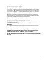
CAUTION
RISK OF ELECTRIC SHOCK
DO NOT OPEN
CAUTION: TO REDUCE THE RISK OF ELECTRIC SHOCK,
DO NOT REMOVE COVER (OR BACK)
NO USER-SERVICEABLE PARTS INSIDE
REFER SERVICING TO QUALIFIED
SERVICE PERSONNEL.
The lightning flash with arrowhead symbol, within an equilateral triangle, is intended to alert the user to the presence of
uninsulated “dangerous voltage” within the product’s enclosure
that may be of sufficient magnitude to constitute a risk of
electric shock.
The exclamation point within an equilateral triangle is intended to alert the user to the presence of important operating
and maintenance (servicing) instructions in the literature
accompanying the appliance.
WARNING:
TO PREVENT FIRE OR SHOCK HAZARD, DO NOT EXPOSE THIS
APPLIANCE TO RAIN OR MOISTURE.
CAUTION:
TO PREVENT ELECTRIC SHOCK DO NOT USE THIS (POLARIZED)
PLUG WITH AN EXTENSION CORD, RECEPTACLE OR OTHER OUTLET UNLESS THE BLADES CAN BE FULLY INSERTED TO PREVENT
BLADE EXPOSURE.
NOTE:
SINCE THIS PROJECTOR IS PLUGGABLE EQUIPMENT, THE
SOCKET-OUTLET SHALL BE INSTALLED NEAR THE EQUIPMENT
AND SHALL BE EASILY ACCESSIBLE.
2
F
COMPLIANCE NOTICE OF FCC
This equipment has been tested and found to comply with the limits for a Class A digital
device, pursuant to Part 15 of the FCC Rules. These limits are designed to provide reasonable protection against harmful interference when the equipment is operated in a commercial environment. This equipment generates, uses, and can radiate radio frequency energy
and, if not installed and used in accordance with the instruction manual, may cause harmful interference to radio communications. Operation of this equipment in a residential area
is likely to cause harmful interference in which case the user will be required to correct the
interference at his own expense.
This digital apparatus does not exceed the Class A limits for radio noise emissions from
digital apparatus as set out in the interference-causing equipment standard entitled “Digital Apparatus”, ICES-003 of the Department of Communications.
Changes or modifications not expressly approved by Mitsubishi could void the user's authority to operate this equipment.
COMPLIANCE NOTICE OF INDUSTRY CANADA
This Class [A] digital apparatus meets all requirements of the Canadian InterferenceCausing Equipment Regulations.
WARNING
Use the attached specified power-supply cord. If you use another cord, it may cause interference with radio and television reception.
Use the attached VGA cable, RS-232C cable with this equipment so as to keep interference
within the limit of a Class A device.
The projector automatically shuts off when the lamp is used up in
about 1,300 hours and not used until lamp replacement.
DO NOT LOOK DIRECTLY INTO THE LENS WHEN PROJECTOR IS IN THE POWER
ON MODE.
3
Contents
Important safeguards ........................................................................... 5
Overview of the projector ..................................................................... 8
Overview of the remote control .......................................................... 12
Battery installation ........................................................................................... 13
Preparing the projector for operation ................................................ 14
Basic connections................................................................................ 16
Cables and adapters .......................................................................................... 17
Projector + IBM PC or IBM PC compatibles (DOS) ......................................... 18
Projector + Macintosh ........................................................................................ 19
Projector + NEC PC-98 and EPSON PC series ................................................ 20
Projector + AV equipment ................................................................................. 21
To operate projector power ON .......................................................... 22
Menu operation................................................................................... 24
MENU layers ..................................................................................................... 24
Basic operation ................................................................................................... 25
NORMAL menu ................................................................................................. 26
GAMMA CORRECTION menu ......................................................................... 27
ENHANCED menu ............................................................................................ 28
POINTER menu ................................................................................................. 30
AUDIO menu ..................................................................................................... 30
OPTION menu ................................................................................................... 31
USER PRESET menu ........................................................................................ 32
Advanced feature for presentation .................................................... 33
Cursor operation ................................................................................................ 33
Expand ................................................................................................................ 34
Super impose ...................................................................................................... 35
PC-CARD ............................................................................................ 36
Advanced feature with PC ................................................................. 38
PCV ..................................................................................................................... 39
PCGC .................................................................................................................. 42
SpacePointer ...................................................................................................... 45
Maintenance ....................................................................................... 47
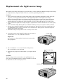
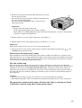
Replacing the lamp ............................................................................. 48
Indicators ............................................................................................ 50
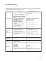
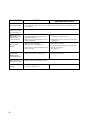
Troubleshooting .................................................................................. 51
Specifications ...................................................................................... 53
Replacement parts list ....................................................................... 54
Trademark, Registered trademark
Apple, Macintosh are registered trademarks of Apple Computer Inc.
IBM, VGA, PS/2, OS/2 are trademarks or registered trademarks of International Business Machines
Corporation.
Microsoft®, Windows®, Windows® 95, Windows NT® are registered trademarks of Microsoft in the U.S.
and other countries.
SpacePointer® is a registered trademark of ALPS ELECTRIC CO., LTD.
Other brand or product names are trademarks or registered trademarks of their respective holders.
4
Important safeguards
PLEASE READ ALL THESE INSTRUCTIONS REGARDING YOUR LCD PROJECTOR
AND RETAIN THEM FOR FUTURE REFERENCE. FOLLOW ALL WARNINGS AND
INSTRUCTIONS MARKED ON THE LCD PROJECTOR.
1.
Read instructions
All the safety and operating instructions should be read before the appliance is operated.
2.
Retain instructions
The safety and operating instructions should be retained for future reference.
3.
Warnings
All warnings on the appliance and in the operating instructions should be adhered to.
4.
Instructions
All operating instructions must be followed.
5.
Cleaning
Unplug this projector from the wall outlet before cleaning it. Do not use liquid aerosol
cleaners. Use a damp cloth for cleaning.
6.
Attachments and equipment
Never add any attachments and/or equipment without the approval of the manufacturer as such additions may result in the risk of fire, electric shock or other personal
injury.
7.
Water and moisture
Do not use this projector near water or in contact with water.
8.
Accessories
Do not place this projector on an unstable cart, stand, tripod, bracket or table. Use only
with a cart, stand, tripod bracket, or table recommended by the manufacturer or sold
with the projector. Any mounting of the appliance should follow the manufacturer's
instructions and should use a mounting accessory recommended by the manufacturer.
An appliance and cart combination should be moved with care. Quick stops, excessive
force and uneven surfaces may cause the appliance and cart combination to overturn.
5
Important safeguards (continued)
9.
Ventilation
Slots and openings in the cabinet are provided for ventilation, ensuring reliable operation of the projector and to protect it from overheating. Do not block these openings or
allow them to be blocked by placing the projector on a bed, sofa, rug, or bookcase. Ensure that there is adequate ventilation and that the manufacturer's instructions have
been adhered to.
10.
Power sources
This projector should be operated only from the type of power source indicated on the
marking label. If you are not sure of the type of power supplied to your office, consult
your appliance dealer or local power company.
11.
Power-cord protection
Power-supply cords should be routed so that they are not likely to be walked on or pinched
by items placed upon or against them. Pay particular attention to cords at plugs, convenience receptacles, and points where they exit from the appliance.
12.
Overloading
Do not overload wall outlets and extension cords as this can result in a fire or electric
shock.
13.
Object and liquid entry
Never push objects of any kind through openings of this projector as they may touch
dangerous voltage points or short-out parts that could result in a fire or electric shock.
Never spill liquid of any kind on the projector.
14.
Servicing
Do not attempt to service this projector yourself as opening or removing covers may
expose you to dangerous voltage or other hazards. Refer all servicing to qualified service personnel.
15.
Damage requiring service
Unplug this projector from the wall outlet and refer servicing to qualified service personnel under the following conditions:
(a) If the power-supply cord or plug is damaged.
(b) If liquid has been spilled, or objects have fallen into the projector.
(c) If the projector does not operate normally after you follow the operating instructions. Adjust only those controls that are covered by the operating instructions.
An improper adjustment of other controls may result in damage and may often
require extensive work by a qualified technician to restore the projector to its
normal operation.
(d) If the projector has been exposed to rain or water.
(e) If the projector has been dropped or the cabinet has been damaged.
(f)
If the projector exhibits a distinct change in performance - this indicates a need
for service.
16.
Replacement parts
When replacement parts are required, be sure that the service technician has used
replacement parts specified by the manufacturer or parts having the same characteristics as the original part. Unauthorized substitutions may result in fire, electric shock or
other hazards.
17.
Safety check
Upon completion of any service or repair to this projector, ask the service technician to
perform safety checks determining that the projector is in a safe operating condition.
6
WARNING:
Unplug immediately if there is something wrong with your projector.
Do not operate if smoke, strange noise or odor comes out of your projector. It might cause fire or
electric shock. In this case, unplug immediately and contact your dealer.
Never remove the cabinet.
This projector contains high voltage circuitry. An inadvertent contact may result in an electric
shock. Except as specifically explained in the Owner's Guide, do not attempt to service this
product yourself. Please contact your dealer when you want to fix, adjust or inspect the projector.
Do not modify this equipment.
It can lead to fire or electric shock.
If you break or drop the cabinet.
Do not keep using this equipment if you break or drop it. Unplug the projector and contact your
dealer for inspection. It may lead to fire if you keep using the equipment.
Do not face a lens to the sun.
It can lead to fire.
Use correct voltage.
If you use incorrect voltage, it can lead to fire.
Do not place the projector on uneven surface. Level stable surface only.
Please do not place equipment on unstable surfaces.
Do not look into a lens.
Do not look into the lens when it is operating. It may hurt your eyes.
Never let children look into the lens when it is on.
Do not turn off the main power abruptly or unplug the projector during
operation.
It can lead to lamp breakage, fire, electric shock or other trouble.
Place of installation
Refrain from setting the projector at any place subjected to high temperature and high humidity.
Precision devices are built into the projector. Please maintain an operating temperature, humidity,
and altitude as specified below for safety's sake.
•
•
•
•
•
Operating temperature: between +41°F (+5°C) and +95°F (+35°C)
Operating humidity: between 30 and 90%
Never put any heat-producing device under the projector so that the projector does not overheat.
Do not attach the projector to a place that is unstable or subject to vibration.
Do not install the projector near any equipment that produces a strong magnetic field. Also
refrain from installing near the projector any cable carrying a large current.
• Place the projector on a solid, vibration free surface: otherwise it may fall, causing serious injury
to a child or adult, and serious damage to the product.
• Do not stand the projector: it may fall, causing serious injury and damage to the projector.
7
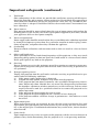
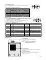
Overview of the projector
lamp lid
Caution:
Do not replace the lamp right after using
the projector. The lamp is very hot. Switch
the projector to stand-by mode, wait at least
120 seconds for the lamp and LCD panel to
cool. Then turn off the main power switch,
unplug from the outlet and wait for another
one hour or until the lamp is cool to the
touch.
exhaust slits
handle
Hold here to carry this projector.
control panel
temperature indicator
This informs you of the thermal condition inside the projector. When
the inside temperature is extremely high, the power automatically
shuts off while the indicator blinks red. See page 49.
lamp indicator
This informs you of the status of the light source lamp and its service
life. When the projector lamp is lit, the indicator lights up in green.
This indicator blinks red when the service life of the lamp is about to
expire (about 1,000 hours). When the lamp is used up to 1,300 hours,
the projector automatically shuts off. See pages 22 & 49.
The projector automatically shuts off when
the lamp is used up in about 1,300 hours and
not used until lamp replacement.
LAMP TEMP
FREEZE EXPAND
SOURCE /CAPTURE /PinP
power indicator
When the main power switch is on in stand-by
mode, this indicator lights up red. When the
projector is fully "ON", the indicator lights up
green. See pages 22 & 49.
power
Use to turn the projector on or off when MAIN POWER is on.
To turn the projector off, press this button twice. See page 22.
input source (input)
Use to select the input source you wish to watch.
See page 23.
freeze / capture
Use to freeze the image. When the PC card is inserted, you can record the “freezed” image. Press one
time to freeze. For the second time hold for 5 seconds to record the image into the card. See page 36.
expand / PinP
Use to change the mode, EXPAND, NATIVE or PinP (Picture in Picture).
See pages 23, 34 & 35.
8
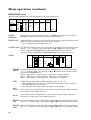
FINE, ADJUST, FOCUS/ZOOM and AUTO buttons
The operations of these buttons vary as follows depending on the modes selected:
FINE (
Normal
On Menu
On PC
card Menu
Adjust FINE (-)
FINE (
º
)
Adjust FINE(+)
ª
FOCUS / ZOOM
Adjust FOCUS or Adjust FOCUS or FOCUS or ZOOM
ZOOM (-)
ZOOM (+)
setting
AUTO
Adjust position
when incorrect
Select the setting Select the setting Set or select the
setting (Down)
item (Left)
item (Right)
Set or select the
setting (Up)
Enter the layer
setting
–
Select the image
(Down)
Select the image
(Up)
Select the
directory (-)
Select the
directory (+)
Select the image Select the image
(Right)
(Left)
–
PinP
EXPAND
)
–
Switch still pictures Switch still pictures Recapture of the
(main or sub)
(main or sub)
still image
Expand different Expand different Expand different Expand different
area (Down)
area (Right)
area (Left)
area (Up)
Set the expand
rate (-)
Select the input
source of PinP
Set the expand
rate (+)
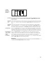
PC card indicator
When the PC card is inserted, these indicators light up. See page 36.
focus / zoom
Use to change the mode of the
adjust buttons, focus or zoom.
CARD1
MENU
CARD2
FINE
FOCUS
/ZOOM AUTO
ENTER
auto
Use to adjust the position of
the image, when the position
is incorrect. See page 23.
ª,º
Use to make FOCUS or ZOOM adjustments.
fine ( , )
Use to make FINE adjustment.
menu
Use to project menu display. See pages 24~32.
9
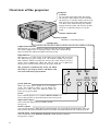
Overview of the projector (continued)
Left side
PC card eject
Press to eject the PC card.
See page 36.
PC card insert slot
This is where you insert the PC card.
(You can insert up to two cards.)
See page 36.
PC audio input (stereo mini jack)
Use to input PC audio signals.
See pages 18~20.
video/audio input
Use to input video and audio.
See page 21.
PC analog RGB input
(mini D-SUB 15P)
Use to input RGB signal for PC.
See pages 18~20.
INPUT 1
PC-1 IN
PC-AUDIO
INPUT 2
MAIN
AUDIO
MAIN power
L
PC-1 OUT
R
AC IN
VIDEO
PC-2 IN
S-VIDEO
RS-232C
power jack
LINE-OUT
S-video input
When connected to this input, S-video functions
automatically shut off normal video input.
See page 21.
RS-232 input (D-SUB 9P)
Use to control the projector
through PC. See page 42.
line output
Use to output PC audio if PC audio in, or Audio input
1 or 2 is connected. See pages 18~20.
PC analog RGB output
(mini D-SUB 15P)
Use to output RGB signal from PC-1 input.
See pages 18~20.
10
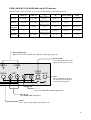
PC analog RGB input
5
1
Use to input video signals (analog RGB) of a personal computer.
6
10
(Pin assignment of Mini D-SUB 15P jack)
PIN NO.
1
2
3
4
5
6
7
8
SPEC
R(RED) / Cr
G(GREEN) / Y
B(BLUE) / Cb
GROUND
GROUND
GROUND
GROUND
GROUND
PIN NO.
9
10
11
12
13
14
15
15
SPEC
GROUND
GROUND
HD/CS
VD
-
RS-232C input
• Connect here when you control this Projector with a personal computer
using PCGC (personal computer graphic controller) or with a remote
controller using SpacePointer function.
• The Pin assignment is DTE (Data Terminal Equipment) type.
• Please use RS-232C crossover cable provided.
11
1
6
5
9
(Pin assignment of D-SUB 9P jack)
NAME
PIN NO. CODE
Carrier Detect
1
CD
Receive Data(RXD)
2
RD
Send Data(TXD)
3
SD
4
ER Equipment Ready(DTR)
5
SG
Signal Ground
6
DR
Data Set Ready(DSR)
7
RS
Request to Send(RTS)
8
CS
Clear to Send(CTS)
9
CI
Ring Indicator
I/O
INPUT
INPUT
OUTPUT
OUTPUT
OUTPUT
OUTPUT
INPUT
INPUT
NOTE
not connected
connected to inner circuit
connected to inner circuit
connected to inner circuit
connected to inner circuit
connected to inner circuit
connected to inner circuit
connected to inner circuit
not connected
Bottom side
foot adjustment
Use to adjust the angle of the projector.
See page 15.
Note: Be sure to retract them when
packing up the projector.
ventilation slots
Used to protect the projector from overheating.
See page 47.
ventilation air filter
This prevents dust from entering inside the
projector. See page 47.
11
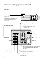
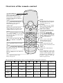
Overview of the remote control
operation indicator
When the operation button is
pressed, this indicator blinks. When
the PC mode or cursor operation
mode is on, this indicator lights up.
See pages 33, 45.
select
This operates in the same way as
the left button on the computer
mouse. See pages 33, 45.
cancel
This operates in the same way as
the right button on the computer
mouse. See pages 33, 45.
start/stop
Use to turn the PC control
mode or cursor operation mode
on or off. See pages 33, 45.
input source (input)
Use to select the input source
you wish to watch. See page 23.
menu, enter, , , ,
Used for MENU setting (see page
25), and used to make FOCUS,
ZOOM or FINE adjustments. See
the table as shown below.
PinP
Press to turn on the PinP
(Picture in Picture) image,
or to cancel it. See page 35.
native
Press to change the size of the
image to native or full screen. See
page 16.
SELECT
double click
This operates in the same way as
double clicking the left button on the
computer mouse. See pages 33, 45.
DOUBLE
CLICK
CANCEL
START/STOP
power
Use to turn the projector on or off
when MAIN POWER is on. To turn
the projector off, press this button
twice. See page 22.
focus / zoom
Use to change the mode of the or
buttons, FOCUS or ZOOM. See
page 23.
expand
Use to expand the image. See page
34.
capture
Use to freeze the image. When the
PC card is inserted, you can record
the image. See page 36.
icon
Press to display the icon menu. See
page 33.
POWER
SOURCE
MENU
FOCUS
/ZOOM
ENTER
EXPAND NATIVE
PinP
CAPTURE
+
-
ICON
AUTO
CURSOR
adjust - / +
See the table as shown below.
cursor
Press to display the cursor. Also
used to change the mode of PC
control or cursor operation, when
the projector is connected to a
personal computer with RS232C. See pages 33, 45.
auto
Use to adjust the position of the
image. See page 23.
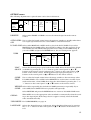
The operations of these buttons varies as follows depending on the modes selected:
$
Normal
On Menu
On PC
card Menu
PinP
EXPAND
12
Adjust FINE (-)
%
Adjust FINE(+)
}
{
Adjust FOCUS or Adjust FOCUS or
ZOOM (-)
ZOOM (+)
adjust -
adjust +
–
–
Select the setting Select the setting Set or select the
setting (Down)
item (Right)
item (Left)
Set or select the
setting (Up)
–
–
Select the image
(Down)
Select the image
(Up)
Select the
group (-)
Select the
group (+)
Select the image Select the image
(Right)
(Left)
–
–
Switch still pictures Switch still pictures Recapture of the
(main or sub)
(main or sub)
still picture
Expand different Expand different Expand different Expand different
area (Down)
area (Right)
area (Up)
area (Left)
Set the expand
rate (-)
Select the input
source of PinP
Set the expand
rate (+)
Important:
• The select, double click, cancel and start/stop buttons are used for PC control. See page 45.
• To save battery power, turn off the operation indicator by pressing the START/STOP button when
not in use.
• To save battery power, the operation indicator will turn off if the remote control is not operated
for a period of 5 minutes.
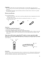
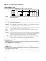
Battery installation
Use two AA size batteries.
1. Remove the back cover of the remote control by pushing the battery compartment door in the
direction of the arrow.
2. Load the batteries making sure that they are positioned correctly (+ to +, and - to -).
3. Replace the back cover.
1
2
3
Important:
1. Do not use a new battery with an old one.
2. Load batteries in the correct position.
3. Do not heat, take apart, or throw batteries into fire.
4. Do not try to recharge batteries. Do not use rechargeable batteries.
5. If the alkaline solution of alkaline batteries comes in contact with your skin or clothes, rinse with
water. If the solution comes in contact with your eyes, rinse them with water and then consult
your doctor.
Operation with remote control for PC mode or cursor operation mode
To move the cursor, press the START/STOP button to ON and move the head of the remote control in
the direction you want the cursor to move. This remote control gives you complete 360˚ control of the
cursor direction.
Move to left
Move to right
Move upward
Move downward
Important:
Point the remote control at the projection screen or at the front or rear of the projector. The range for
optimum operation is about 25 feet. If you point the remote at the projection screen, the distance to
the screen and back to the projector must be less than 25 feet.
13
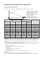
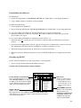
Preparing the projector for operation
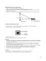
Orientation of the projector
Picture size can be set by changing the distance between the screen and the projector.
screen
To find the approximate distance
between the projector and screen:
Multiply the width of the screen
x 1.85 ⵑ 1.95 (max.) ,
Multiply the width of the screen
x 2.33 ⵑ 2.53 (min.) ,
• Refer to the chart to recommended distaces in maximum
zoom and minimum zoom.
H (height)
L (between the screen and center of the head of the lens-barrel)
Screen
Diagonal size Height inches
(inch)
(inch)
Width feet
(inch)
20 "
12 "
16"
40 "
24 "
32 "
60 "
36 "
48 "
80 "
48 "
64 "
100 "
60 "
80 "
120 "
72 "
96 "
140 "
84 "
112 "
160 "
96 "
128 "
180 "
108 "
144 "
200 "
120 "
160 "
300 "
180 "
240 "
Distance from screen (L) /
Height projected
(inches) (approximate)
image
(H) / (inches)
Maximum Minimum
(approximate)
zoom (min.) zoom (max.)
–
59"
91"
122"
154"
185"
217"
248"
280"
311"
468"
37"
78"
119"
160"
201"
242"
283"
324"
365"
406"
–
1.5"
3.0"
4.5"
6.0"
7.5"
9.0"
10.5"
12.0"
13.5"
15.0"
22.5"
Caution:
• Placing the projector on a carpet reduces ventilation from the fan on the bottom and might cause
problems. Place a hard board or similar item under the projector to facilitate ventilation of the
unit.
• Place the projector more than 8 in. from the wall to prevent blocking the intake, exhaust slots and
ventilation of this projector because hot air comes out of it.
• Do not use the projector under the following circumstances, which may cause fire or electric
shock.
• in a dusty or humid place
• while the projector is lying sideways or upside down.
• near a heater
• in a kitchen or oily, smoky or damp place
• in direct sunlight
• where the temperature is lower than 41°F or higher than 95°F
Important:
• Do not put stress on the lens or focus ring, as this may damage them.
• Keep your room dark while using the projector. The image cannot be seen clearly in a bright place.
14
Adjusting the angle of projection
• Screen on a flat wall with a 90˚ angle to the floor.
• Align projector to produce a full screen display as illustrated on page 14.
• Distance from projector to screen must be compatible with screen size chart on page 14. Note
distance from screen chart.
• If image is not square on screen, try adjusting the front feet of the projector for proper angle.
screen
foot adjustment
Getting ready for projection
1. Connect the power cord provided to this projector with the power jack of the projector.
2. Connect the power cord to the wall outlet.
Plug in the provided
power cord directly.
ground
terminal
3. Take off the lens cap.
4. Do not look directly into the lens when projector is “ON”.
Warning:
• A three-pin grounding type power plug is used with the projector. Do not remove the grounding
pin on the power plug. If you are unable to insert the plug into the outlet, contact your electrician
to replace your obsolete outlet.
• The supplied power cord is used for 120V only. Never connect to any outlet or power supply
having a different voltage or frequency. If you connect to the power supply having a different
voltage, please use the appropriate power cord.
• Do not place an object on the power cord and keep the projector away from heat source to avoid
breaking the power cord. A broken of power cord can cause fire or electric shock.
• Do not revise or alter the power cord otherwise it may cause fire or electric shock.
Contact your dealer if the cord is broken.
Caution:
• Plug in firmly and unplug by holding the plug, not by pulling the cable out.
• Do not plug in or out with wet hands. It may cause an electric shock.
15
Basic connections
This projector can be connected to equipment such as VCRs, video cameras, videodisc players, and
personal computers having analog RGB input.
Important:
• Make sure that your equipment is turned off before connection.
• Match the color of video and audio plugs on the AV cable with each terminal.
• Plug in firmly and unplug by holding the plug, not by pulling the cable out.
• If connected units are set too close to one another, the image may be affected. Setting connected
units too close to one another affects the image.
• Refer to the owner's guide of each component for details of connections, .
To connect to IBM PC or IBM PC compatibles.
To connect to Macintosh.
To connect to the series of PC-98, EPSON PC.
To connect to AV equipment.
Specification of RGB signals in each computer mode of this projector
signal mode
AT (VGA)
MAC (13 inch mode)
MAC (16 inch mode)
MAC (19 inch mode)
MAC (21 inch mode)
PC98
SVGA
XGA
SXGA
SXGA
SXGA
•
•
•
•
example of usable computer
resolution (H ✕ V)
horizontal frequency (KHz)
DOS machine
640 ✕ 480
60, 72, 75, 85
Apple Macintosh
640 ✕ 480
67
Apple Macintosh
832 ✕ 624
75
Apple Macintosh
1024 ✕ 768
75
Apple Macintosh
1152 ✕ 870
75
NEC PC98
640 ✕ 400
56, 70
Video card etc.
800 ✕ 600
56, 60, 72, 75, 85
Video card etc.
1024 ✕ 768
43, 60, 70, 75, 85
Video card etc.
1152 ✕ 864
70, 75, 85
Video card etc.
1280 ✕ 960
60, 75
Video card etc.
1280 ✕ 1024
60, 72, 75
The projector is not compatible with SYNC on G (Green) of an SXGA signal.
The projector is not compatible with an SXGA signal increased by the interlacing method.
The picture with a SYNC on G (Green) signal may be tinged with green.
The picture with a SYNC on G (Green) signal may vibrate.
Specification of RGB signals in each computer mode of the projector
By pressing the "NATIVE" button of the remote control, it will switch to the screen displaying the
picture as its original size (real screen display). In the real screen display, pictures will be blackframed when picture resolution is lower than 1,024 ✕ 768.
Any part of the picture will not be affected, if the picture resolution is higher than 1,024 ✕ 768.
Pressing the EXPAND/PinP button on the control panel also switches to the real screen display. Keep
holding the EXPAND/PinP button until the real screen display appears.
Important:
• Some computers may not be compatible with the projector.
• The projector's maximum resolution is 1,024 ✕ 768. pixel. It may not be displayed correctly for the
pictures of higher resolutions than 1,024 ✕ 768.
• For the signals of the other format than the above, please make setting in the preset menu. (See
page 32.)
16
Order of turning on / off
Turn on equipment in the following order to avoid trouble.
1. PC monitor
2. AV equipment
3. Projector
4. Personal computer
Turn off the equipment in the reverse order.
Important:
Some computers may not be compatible with this projector.
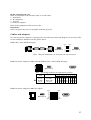
Cables and adapters
To connect personal computers to this projector, the following cables and adapters are necessary. The
overview might be different from the picture below.
RGB cables (mini D-SUB 15P plug)
PIN NO.
1
2
3
PIN NO.
1
2
3
•
•
MINI D-SUB 15P
•
•
•
•
13
14
15
13
14
15
MINI D-SUB 15P
Note: The pins numbered 5, 9, 12 and 15 are not connected.
RGB Conversion adapter for MAC (mini D-SUB 15P jack - mini D-SUB 15P plug)
ON
1
2
3
4
5
6
7
8
9
MINI D-SUB 15P
D-SUB15P
10
Note: Set the dip switch to the appropriate position.
%
Display
mode
13 inch
16 inch
19 inch
21 inch
Resolution
640 ✕ 480
832 ✕ 624
1024 ✕ 768
1152 ✕ 870
1
ON
ON
ON
ON
Dip switch
2 3 4 5 6
OFF OFF ON OFF ON
OFF ON OFF OFF ON
ON OFF OFF OFF ON
ON ON ON OFF ON
7
ON
ON
ON
ON
8 9 10
OFF OFF OFF
OFF OFF OFF
OFFOFF OFF
OFF OFF OFF
RGB Conversion adapter for NEC PC (Option)
MINI D-SUB 15P
PIN NO.
1
2
3
5
6
7
8
10
13
14
SHELL
PIN NO.
1
3
5
8
2
4
6
12
14
15
SHELL
D-SUB15P
17
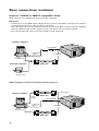
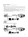
Basic connections (continue)
Projector + IBM PC or IBM PC compatibles (DOS)
Make sure that your equipment is turned off before connection.
Important:
• Connectors or analog RGB output adapters may be necessary depending on the personal computer
connected to this projector. Please contact your dealer.
• The audio input for a personal computer is the stereo mini-jack. There are some personal computers
that have different types of audio outputs or none at all. Please ask your dealer for details.
• For connection details, refer to the owner's guide of each component.
desktop computer
to PC-AUDIO
to PC audio
output
to PC-1 IN
to VGA
monitor port
RGB cable
notebook computer
to VGA
monitor port
When outputting to both a PC monitor and the projector
to PC-1 OUT
desktop computer
RGB cable
to PC
monitor
to PC-AUDIO
to PC audio
output
to PC-1 IN
to VGA
monitor port
RGB cable
18
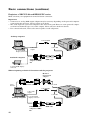
Projector + Macintosh
Make sure that your equipment is turned off before connection.
Important:
• A monitor output adapter is necessary for a Macintosh if it has no video port. Contact your dealer.
• If you use the RGB conversion adapter provided, set the dip switch to the appropriate position. See
page 17.
• Connectors or analog RGB output adapters may be necessary depending on the personal computer
connected to this projector. Please contact your dealer.
• The audio input for a personal computer is the stereo mini jack. There are some personal computers
that have different types of audio outputs or none at all. Please ask your dealer for details.
• For connection details, refer to the owner's guide for each component.
• When outputting to both a PC monitor and the projector, use an Apple Macintosh monitor or multiscan
monitor corresponding to Composite Sync.
desktop computer
to PC-AUDIO
to PC audio
output
to PC-1 IN
Power Book
1
ON
2
3
4
5
6
7
8
9
10
to video port
RGB Conversion
adapter for MAC
RGB cable
to video port
When outputting to both a PC monitor and the projector
Monitor
Conversion
adapter
to PC
monitor
Monitor cable
to PC-1 OUT
to PC-AUDIO
to PC audio
output
to PC-1 IN
ON
2
3
4
5
6
7
8
9
10
to video port
1
desktop
computer
RGB Conversion
adapter for MAC
RGB cable
19
Basic connections (continue)
Projector + NEC PC-98 and EPSON PC series
Make sure that your equipment is turned off before connection.
Important:
• Connectors or analog RGB output adapters may be necessary depending on the personal computer
connected to this projector. Please contact your dealer.
• The audio input for a personal computer is the stereo mini jack. There are some personal computers that have different type or no audio outputs. Please ask your dealer for details.
• For connection details, refer to the owner's guide of each component.
desktop computer
to PC-AUDIO
to PC-IN1
to PC audio
output
to analog RGB
display connector
notebook computer
RGB Conversion
adapter for NEC
PC
RGB cable
to analog RGB display
connector
When outputting to both a PC monitor and the projector
Monitor
Conversion
adapter
to PC
monitor
to PC-1 OUT
Monitor cable
to PC-AUDIO
to PC audio
output
to PC-IN1
desktop computer
to analog RGB
display connector
RGB Conversion
adapter for NEC
PC
20
RGB cable
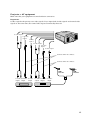
Projector + AV equipment
Make sure that your equipment is turned off before connection.
Important:
S-video signals take priority over video signals. If you input both S-video signals and normal video
signals at the same time, the normal video input automatically shuts off.
to audio input 2
to S-video
input 2
to video
input 2
to audio input 1
to S-video
input 1
to video input 1
Connect either one of these.
Connect either one of these.
UHF
antenna
to audio to S-video to video
output
output output
DVD player, others
VHF
antenna
to audio to S-video to video
output
output output
VCR, others
21
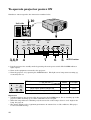
To operate projector power ON
Numbers 1~10 correspond to the instruction numbers below.
1, 10
Left side
INPUT 1
PC-1 IN
PC-AUDIO
INPUT 2
MAIN
AUDIO
L
PC-1 OUT
R
AC IN
VIDEO
PC-2 IN
4
S-VIDEO
RS-232C
LINE-OUT
LAMP TEMP
CARD1
FREEZE EXPAND
SOURCE /CAPTURE /PinP MENU
CARD2
FOCUS
/ZOOM AUTO
FINE
ENTER
3, 8, 9
4
7
6
5
AUTO button
1. Put the projector into standby mode by pressing the main power switch. The POWER indicator
lights up red.
2. Turn on the equipment connected to the projector.
3. Turn the projector on by pressing the POWER button. The light source lamp starts warming up,
eventually turn on.
indicator
condition
LAMP TEMP
FREEZE
SOURCE /CAPTURE
LAMP
POWER
stand-by
-
red
when light source lamp is on
green
green
when light source lamp does not light up
-
red
Important:
• A darkened image may be seen right after pressing the POWER button due to warming up of this
projector. When warming up, no other commands can be accepted.
• When the lamp indicator is blinking red, the service life of the lamp is about to end. Replace the
lamp. See page 48.
• The picture might not be of optimum performance in extreme hot or cold conditions. (The projector is not malfunctioning.)
22
4. Select the desired external input source by using the SOURCE button.
The source changes in the sequence shown below:
VIDEO1
(PC2)
VIDEO2
(PC1)
RGB1
RGB2
• The projector automatically selects the appropriate signal system. When the source is selected to
RGB1 or RGB2 and the image is not in the right place, set to display as blightest signal as possible, then press the AUTO button. If the image is still not in the right place, refer to USER
PRESETS on page 32.
• The projector automatically convert the image into full screen size. By pressing the NATIVE
button, the native size image will appear.
5. Press the FOCUS/ZOOM button to FOCUS. “FOCUS” will appear on the display.
6. Adjust with the ª or º buttons on the control panel (or { or } buttons on the remote control)
to get a fine picture.
7. Adjust with the FINE
or
buttons on the control panel (or $ or % buttons on the remote
control) to get a clear picture.
• Focus and zoom adjustment by using the buttons on the control panel or the remote control is
possible in the normal picture mode only. In PinP, EXPAND or cursor operation mode, the adjustment is impossible.
Turning off the projector
8. Press the POWER button.
The message “POWER OFF? YES : PRESS AGAIN” appears on the screen.
• To exit from this mode, press any button except POWER button.
9. Press the POWER button again.
The light source lamp will be turned off.
By pressing the POWER button again, shuts off the light source lamp, but the exhaust fan continues to operate for 120 seconds to cool down the light source lamp and LCD panels.
10. Turn off the main power switch. When turning off the main switch, the POWER indicator turns off.
Caution:
• When you have finished using this equipment, wait 120 seconds for the exhaust fans to stop. Then
turn off the main switch and unplug the power cable from the wall outlet, for safety purposes.
• After the lamp is turned off, the lamp cannot be switched on again for 60 seconds as a precautionary measure. It will take another 60 seconds before the lamp indicator goes off. If you wish to
turn on the projector again, wait until the indicator is off then press the POWER button.
• Focus or zoom adjustment by the projector or the remote control is possible in the normal picture
mode only. Ii is not possible to adjust when menu, PinP, zooming picture and cursor operation are
activated.
The projector automatically shuts off when the lamp is used up in about
1,300 hours and not used until lamp replacement.
23
Menu operation
Several settings can be adjusted using Menu. There are 5 modes. You can also make adjustments
using PCGC (personal computer graphic controller). See pages 42 ~ 44 for details.
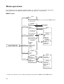
MENU layers
HELP
HELP
By selecting the HELP, you can view the MENU layers
on the screen.
NORMAL
See page 26.
CONTRAST
BRIGHTNESS
TINT
COLOR
GAMMA CORRECTION
ENHANCED
See page 28.
IMAGE REVERSE
ZOOM/SUPER
SOURCE ID
BLUE BACK
TEST PATTERN
POINTER
MAIN MENU
See page 30.
CURSOR
SELECT
SIZE
DEFAULT POS
CURSOR TRAILS
COLOR
WIDTH
R/G/B
R/G/B
USER
MASTER
R
G
B
ZOOM
FRAME MODE
SIZE
PAN
FRAME POS
FRAME SIZE
SUPER
IMPOSE
SOURCE
FRAME POS
FRAME SIZE
AUDIO
See page 30.
VOLUME
MUTE
USER
OPTION
See page 31.
RECIEVE
AUTO POWER OFF
PC CARD PLAY
SIGNAL
USER PRESETS
LANGUAGE
PLAY GROUP
SLIDE TIME
REPEAT SLIDE
USER
H-POS / V-POS
TRACKING
WIDTH / HEIGHT
FINE SYNC
CLAMP
RGB / Y, Cb, Cr
• If the menu operation is not working, simultaneously press the MENU and POWER button.
24
Basic operation
EXAMPLE:
Brightness adjustment
LAMP TEMP
CARD1
FREEZE EXPAND
SOURCE /CAPTURE /PinP MENU
CARD2
3
FOCUS
/ZOOM AUTO
FINE
POWER
ENTER
MENU
1, 5
1, 5 3
SOURCE
FOCUS
/ZOOM
2, 4
ENTER
2, 4
1. Press the MENU button onceto display the on-screen menu.
HELP
NORMAL
CONTRAST
BRIGHTNESS
0
0
R/G/B
TINT
0
R/G/B
COLOR GAMMA CORRECTION
0
USER
ENHANCED
POINTER
AUDIO
OPTION
QUIT
RESET
2. Press the ª or º buttons on the control panel (or { or }
buttons on the remote control unit) to select NORMAL.
HELP
CONTRAST
BRIGHTNESS
0
0
NORMAL
R/G/B
R/G/B
ENHANCED
POINTER
AUDIO
OPTION
QUIT
3. Press the
or buttons on the control panel (or$ or %
buttons on the remote control unit) to select BRIGHTNESS.
HELP
CONTRAST
BRIGHTNESS
0
0
NORMAL
R/G/B
R/G/B
ENHANCED
POINTER
AUDIO
OPTION
QUIT
4. Press the ª or º buttons on the control panel (or { or }
buttons on the remote control unit) to adjust brightness.
HELP
CONTRAST
0
NORMAL
BRIGHTNESS
-15
R/G/B
R/G/B
ENHANCED
POINTER
AUDIO
OPTION
QUIT
5. Exit the menu system by pressing the MENU button or the ENTER button to QUIT.
• To switch back to the factory preset of each menu, select RESET and press the ENTER button.
• When selecting RESET, the buttons cannot be operated for 2 to 18 seconds.
25
Menu operation (continue)
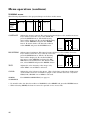
NORMAL menu
The following adjustments to the projected image can be done in this menu.
HELP
CONTRAST
BRIGHTNESS
0
0
NORMAL
R/G/B
TINT
0
R/G/B
COLOR GAMMA CORRECTION
0
USER
ENHANCED
POINTER
AUDIO
OPTION
RESET
QUIT
CONTRAST
Adjusts the picture contrast. The contrast becomes higher as the number increases.
If you wish to select the color, select R/G/B and
R
G
B
CONTRAST
press the ENTER button. (The R/G/B setting
0
0
0
menu will be displayed.) To exit the R/G/B setting
menu, select RETURN and press the ENTER
button. To switch back to the default condition,
select RESET and press the ENTER button.
RESET
RETURN
BRIGHTNESS Adjusts image brightness. The image becomes brighter as the number increases.
If you wish to select the color, select R / G / B and
press the ENTER button. (The R / G/ B setting
menu will be displayed.) To exit the R/G/B setting menu, select RETURN and press the ENTER button. To switch back to the default condition, select RESET and press the ENTER button.
BRIGHTNESS
RETURN
R
G
B
0
0
0
RESET
TINT
Adjusts the color intensity of the image (only
when NTSC or 4.43 NTSC is selected).
COLOR
Adjusts the color balance in the image. The color balance of the image shifts green
as the number increases and shifts to purple as the number decreases (only when
NTSC, PAL, SECAM or 4.43 NTSC is selected).
GAMMA
CORECTION
For GAMMA CORRECTION, see page 27.
• To switch back to the default condition of NORMAL, select RESET and press the ENTER button.
• When selecting RESET, the buttons cannot be operated for 2 to 18 seconds.
26
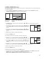
GAMMA CORRECTION menu
The proportion of the brightness of input signals to that of output signals can be corrected effectively
by adjusting GAMMA.
1. Select GAMMA CORRECTION of NORMAL menu and then press the ENTER button. (The
GAMMA CORRECTION menu appears on-screen display.)
GAMMA
CORRECTION
MASTER
R
G
B
RETURN
Horizontal axis:
Vertical axis:
Inclination:
RESET
brightness of the input signals
brightness of the output signals
GAMMA
2. Press the ª or º buttons on the control panel (or { or } buttons on the remote control) to
select MASTER.
3. Press the
or
buttons on the control panel (or $ or % buttons
on the remote control) to select the points brightness of the input
signals.
GAMMA
CORRECTION
MASTER
R
G
4. Press the ª or º buttons on the control panel (or { or } buttons on the remote control) to adjust the brightness of the output
signals.
B
RETURN
5. Repeat steps 3 and 4 for another point setting.
6. Press the ENTER button.
If you wish to change the color balance, follow the steps below.
7. Press the ª or º buttons on the control panel (or { or }
buttons on the remote control) to select the desired color R, G or B.
GAMMA
CORRECTION
MASTER
R
8. Press he
or
buttons on the control panel (or $ or % buttons
on the remote control) to select the points brightness of the input
signals.
G
B
RETURN
9. Press the ª or º buttons on the control panel (or { or }
buttons on the remote control) to adjust the brightness of the output signals.
10. Repeat steps 3 and 4 for another point setting.
11. Press the ENTER button.
12. Exit the menu system by pressing the MENU button.
• To switch back to the default condition of GAMMA CORRECTION, select RESET and press the
ENTER button when the GAMMA CORRECTION display appears.
• When selecting RESET, the buttons cannot be operated for 2 to 18 seconds.
27
Menu operation (continue)
ENHANCED menu
The following adjustments for enhanced items can be done in this menu.
HELP
IMAGE
REVERSE KEYSTONE
NORMAL
OFF
ENHANCED
POINTER
AUDIO
OPTION
QUIT
MIRROR
INVERT
MIRROR
INVERT
ZOOM/
SUPER
SOURCE ID BLUE BACK
0˚
3˚
6˚
9˚
ZOOM
TEST
PATTERN
ON
ON
OFF
OFF
OFF
1
2
SUPER
IMPOSE
3
12˚
4
15˚
5
RESET
IMAGE
REVERSE
Use to reverse or invert the projected image. MIRROR is usedfor rear projection.
INVERT is effective when the projector is ceiling-mounted.
KEYSTONE
Adjusts keystone correction of the image. If the image becomes keystone distortion,
select the approximate setting. For normal use, select 0˚.
• Do not adjust keystone in the PinP mode.
ZOOM/SUPER Sets the detail settings for zoom or super impose. Select the desired items by pressing the ª or º button on the control panel (or { or } button on the remote
control) and press the ENTER button. The desired setting menu appears.
(For more details for ZOOM and SUPER IMPOSE, refer to pages 34 and 35.)
ZOOM
ZOOM
FRAME
MODE
SIZE
H-POS
1
2
FRAME
POS
PAN
0
V-POS
0
FRAME
SIZE
1
1
2
2
3
3
4
3
RETURN
0
RESET
FRAME Selects the desired type of zoom. Select the desired type, 1, 2 or 3 by pressing the
MODE ª or º buttons on the control panel (or { or } buttons on the remote control)
and press the ENTER button.
Type 1 : Main image = normal picture , Sub image = zooming picture
Type 2 : Main image = zooming picture , Sub image = normal picture
Type 3 : Main image = zooming picture , Sub image = not appears.
SIZE
PAN
V-POS
H-POS
Adjusts zoming magnification. The selectable values are 1.0 - 5.0.
• The magnification for zooming is actually the magnification of the vertical or
horizontal direction, not the area.
• The selectable value may change according to other settings.
Use to make vertical adjustments to the position of the sub-image. The sub-image
moves down as the number increases.
Use to make horizontal adjustments to the position of the sub-image. The subimage moves to the right as the number increases.
FRAME Selects the desired position of the sub-image. Select the desired position by pressing
the ª or º buttons on the control panel (or { or } buttons on the remote control) .
POS
FRAME Selects the desired size of the sub-image. Select small, medium or large by pressing
the ª or º buttons on the control panel (or { or } buttons on the remote control).
SIZE
28
SUPER
IMPOSE
(Picture in
Picture)
SUPER
IMPOSE
RETURN
SOURCE
FRAME
POS
VIDEO1
1
1
VIDEO2
RGB1
RGB2
PC1
PC2
2
2
3
3
FRAME
SIZE
4
5
RESET
SOURCE Selects the desired input source of the sub-image. Select the desired input source
by pressing the ª or º buttons on the control panel (or { or } buttons on the
remote control).
FRAME Selects the desired position of the sub-image. Select the desired position by pressing
POS
the ª or º buttons on the control panel (or { or } buttons on the remote control).
FRAME Selects the desired size of the sub-image. Select the desired size: small, middle or
SIZE
large by pressing the ª or º buttons on the control panel (or { or } buttons on
the remote control). Selecting No. 5 of FRAME POS doesn’t change the frame size.
SOURCE ID
Use to set SOURCE ID on or off. If you select OFF, the mode display automatically
disappears after about four seconds. If you select ON, the mode display continues to
appear. The SOURCE ID is automatically set to OFF, when the power is turned off.
BLUE BACK
(VIDEO MUTE)
Use to set BLUE BACK on or off. When there is no input signal, the projector
displays a blue screen. Select OFF if you don’t want to display a blue background.
TEST
PATTERN
Use to display the built-in test pattern on the screen. There are five different
patterns. Select the desired pattern by pressing the ª or º buttons on the control
panel (or { or } buttons on the remote control).
Important:
To make the test pattern disappeared, press the buttons except FOCUS/ZOOM, + or
- buttons while the MENU display in not on screen.
29
Menu operation (continue)
POINTER menu
The following adjustments to the cursor and cursor trails can be done in this menu.
CURSOR
SELECT
HELP
NORMAL
ENHANCED
POINTER
AUDIO
1
2
3
4
5
SIZE
1
2
3
OPTION
DEFAULT POS
CURSOR TRAILS
COLOR
H-POS
V-POS
50
50
QUIT
CURSOR
SELECT
1
2
3
4
5
6
7
WIDTH
1
2
3
4
5
6
RESET
Selects the desired color of the cursor. Select the desired color by pressing the ª or
º buttons on the control panel (or { or } buttons on the remote control).
Selects the desired size of the cursor. Select the desired shape by pressing the ª or
º buttons on the control panel (or { or } buttons on the remote control).
SIZE
DEFAULT POS
V-POS
Use to make vertical adjustments to the position of the cursor. The cursor moves
down as the number increases.
H-POS
Use to make horizontal adjustments to the position of the cursor. The cursor moves
to the right as the number increases.
CURSOR TRAILS
COLOR
Selects the desired color for the cursor trail. Select the desired color by pressing the
ª or º buttons on the control panel (or { or } buttons on the remote control).
WIDTH
Selects the desired width of the cursor trail. Select the desired width by pressing
the ª or º buttons on the control panel (or { or } buttons on the remote control).
AUDIO menu
HELP
VOLUME
MUTE
30
NORMAL
ON
ENHANCED
OFF
POINTER
AUDIO
OPTION
QUIT
RESET
AUDIO
Adjusts the volume of sound. The volume becomes louder as the number increases.
MUTE
Use to set MUTE on or off. Select ON to switch off the sound. Select OFF to switch
the sound back on.
30
OPTION menu
The following adjustments to optional items can be done in this menu.
RECEIVE AUTO POWER OFF PC CARD PLAY
HELP
FRONT
NORMAL
USER
30
SIGNAL
MANUAL
AUTO
AUTO
NTSC
NO
Espanol
PAL
Deutsche
Francais
4.43NTSC
Italiano
USER
AUDIO
English
USER
SECAM
ENHANCED
POINTER
USER PRESETS LANGUAGE
OPTION
RESET
REAR
QUIT
RECEIVE
Select either FRONT or REAR to receive the infrared signal from the remote
control.
AUTO POWER Use to select the length of time before the projector switches to standby when there
is no input signal selected source. Select OFF to cancel this function.
OFF
PC CARD PLAY Select either MANUAL or AUTO mode to play back the PC CARD. If you select
MANUAL, the PC CARD will be played back according to the key operation. If you
select AUTO, the PC CARD will be played back according to the USER setting. If
you select USER and press the ENTER button, the user setting menu appears.
USER
PC CARD PLAY
PLAY GROUP
SLIDE TIME
REPEAT SLIDE
GRP1
SLOT 1
GRP2
DEFAULT
ON
OFF
USER
SLOT 2
1.0 min
RESET
RETURN
º
Selects the desired group to play back the PC CARD. Select the desired slot (SLOT1
PLAY
GROUP or SLOT2) by pressing the ª or º buttons on the control panel (or { or }
buttons on the remote control) and press the button on the control panel (or %
button on the remote control). Select the desired group by pressing the ª or º
buttons on the control panel (or { or } buttons on the remote control).
SLIDE
TIME
Use to select the length of time before the image switches to the next image when
PC CARD PLAY is set to AUTO. Select DEFAULT to set the time to 1.0 min. If you
wish another time, select USER, then select the desired time by pressing the ª or
º buttons on the control panel (or { or } buttons on the remote control).
REPEAT Select ON to repeatedly play back the PC CARD presentation repeatedly. If you
SLIDE select OFF, the PC CARD will not be played back repeatedly.
Select RETURN and press the ENTER button to return to PC CARD PLAY menu.
SIGNAL
When AUTO is set, the appropriate video standard is automatically selected according to the input signal. If the image does not appear correctly, select the desired
video standard manually.
USER PRESETS For USER PRESETS, see page 32.
LANGUAGE
Selects the desired language of the menu. Select the desired language by pressing
the ª or º buttons on the control panel (or { or } buttons on the remote control).
31
Menu operation (continue)
USER PRESETS menu
If you select USER and press the ENTER button, the user setting menu appear.
HELP
USER
PRESETS
H-POS / V-POS
TRACKING
WIDTH / HEIGHT
H-POS
NORMAL
FINE
SYNC
CLAMP
WIDTH
HEIGHT
ENHANCED
V-POS
POINTER
0
RGB/
Y,Cb,Cr
0
0
0
0
RGB
MEMORY
Y,Cb,Cr
AUDIO
0
OPTION
QUIT
0
RETURN
H-POS
Use to adjust the horizontal position of the image. The image moves to the right as
the number increases.
V-POS
Use to adjust the vertical position of the image. The image moves down as the
number increases.
TRACKING
Use to match the clock signals of the projector with the input signal to avoid image
noise such as wide stripes.
HEIGHT
Use to adjust the height of the image. The image size grows higher as the number
increases. (Normally, there is no need for adjustments.)
WIDTH
Use to adjust the width of the image. The image size grows wider as the number
increases. (Normally, there is no need for adjustments.)
FINE
SYNC
Use to synchronize the projector with PC input signals so that the image is not
blurred.
CLAMP
Use to adjust the level of luminance. The projector does not need this adjustment
for ordinary use. If you use a PC video card or something similar, the lighter colors
of the projected image may become blurred. In this case, adjust CLAMP.
When the equipment (DVD player system, etc.) with Y, Cb, Cr connectors is conRGB /
Y, Cb, Cr nected to the PC-1 or PC-2 connector, select [Y, Cb, Cr]. Depending on the DVD
player, the image may not be projected correctly with this projector.
The simple way of adjustment
1. Horizontal position:
Adjust the start position (the left end) using H-POS, and adjust the end position (the right end)
using TRACKING. Then repeat these steps.
2. Vertical position:
Adjust the start position using V-POS.
• If you change the settings of the USER PRESETS, you must select MEMORY and press the
ENTER button.
• The projector is able to memorize 2 signals setting. When reached over 2, settings of the signals
will be deleted in chronologic order.
• By pressing the + button, you can change the setting among the default condition and memorized
condition.
32
Advanced feature for presentation
Cursor operation
1. Press the CURSOR button.
The cursor appears on the screen.
• The default position where the cursor appears on the screen can be set by using this on-screen
menu.
2. Press the START/STOP button to ON.
The operation indicator will be illuminated.
(The operation indicator will turn off if the remote control is not used for a period of five minutes.)
3. Move the cursor by using the remote control.
Refer to page 13 for moving the cursor.
4. Press the START/STOP button to momentarily freeze the cursor movement. Press again to resume moving.
5. Press the CURSOR button to cause the cursor to disappear.
To draw a freehand line
1. Press the ICON button.
The pen, eraser, color of the cursor trails and the width of the cursor icons
appear on the screen.
2. Select the pen icon, then press the SELECT button.
• If necessary, change the color or width of the cursor trails by selecting
the icon and pressing the SELECT button repeatedly.
Width
Color
Pen Eraser
3. Position the cursor where you want the path to begin.
4. Press and hold the SELECT button, moving the cursor to draw a path.
To draw square lines
1. Move the cursor to where you want the point of one corner of the
square, and press the DOUBLE CLICK button. The cross mark appears.
2. Move the cursor to where you want the point of the opposite corner
and press the DOUBLE CLICK button again.
3. For more square lines, repeat steps 1 and 2.
• The cross mark will be disappeared by pressing the CANCEL button.
To erase lines
1. Press the ICON button.
The pen, eraser, color of the cursor trails and the width of the cursor icons appear on the screen.
2. Select the eraser icon, then press the SELECT button.
3. Press and hold the SELECT button, moving the cursor to erase lines.
• By pressing the CURSOR, MENU, EXPAND, NATIVE or PinP buttons, the cursor trails will
disappear.
• You can also select the color and width of the cursor trails by using the on-screen menu.
• When the MENU appears, the cursor will disappear.
• When the cursor appears, the source ID will disappear.
• You can not adjust the zoom/focus in the cursor operation mode.
33
Advanced feature for presentation (continued)
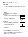
Expand
By pressing the EXPAND button on the remote control, you can view the detailed image of the
picture.
1. Press the MENU button once to display the on-screen menu.
2. Press the ª or º buttons on the control panel (or { or } buttons on the remote control) to
select ENHANCED.
3. Press the
or
buttons on the control panel (or $ or % on the remote control) to select PC
ZOOM/SUPER.
4. Press the ª or º buttons on the control panel (or { or } buttons on the remote control) to
select ZOOM and then press the ENTER button.
FRAME
MODE
ZOOM
SIZE
H-POS
1
2
FRAME
POS
PAN
0
V-POS
0
FRAME
SIZE
1
1
2
2
3
3
4
0
3
RESET
RETURN
5. Set the FRAME MODE, SIZE, PAN, FRAME POS and FRAME SIZE.
6. Press the
or
buttons on the control panel (or $ or % buttons on the remote control) to
select RETURN and then press the ENTER button.
7. Press the MENU button to exit the menu system.
8. Press the EXPAND button. Pressing the EXPAND button repeatedly will select on and off.
Normal picture
Normal
picture
Zooming
picture
Normal
picture
Zooming
picture
Zooming picture
• You can magnify different areas of the active picture by pressing the ª , º,
or
buttons on
the control panel (or {, }, $ or % buttons on the remote control). If you press and hold the {,
}, $ or % buttons on the remote control, the area is changed continuously.
• You can change the magnification of the zoomed area by pressing the + or - buttons. If you press
and hold the + or - buttons on the remote control, the magnification is changed continuously.
• When the source is selected to VIDEO1, VIDEO2, PC1 or PC2, the expand function will not work.
• If you press the CURSOR button, the expanded area will disappear.
• In EXPAND mode, do not display the test pattern.
• In EXPAND mode you cannot adjust the zoom/focus.
34
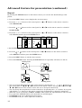
Super impose (Picture in Picture)
One of the special features of this unit is the picture-in-picture (PinP) mode. PinP allows you to view
different sources at the same time. The sub image will become a still picture.
1. Press the PinP button on the remote control. Pressing the PinP button repeatedly will select on
and off.
• In PinP mode, the sound will be switched off.
• When the main image is set to PC1 or PC2, the main and sub image will become still pictures.
• When the main image and sub image are set to RGB1, RGB2, VIDEO1 or VIDEO2, the sub image
is recaptured by pressing the ‘-’ button.
• When the sub image is set to PC1 or PC2, the sub image is not recaptured by pressing the ‘-’
button.
• The sub image may vibrate. If this is the case, select the image again by pressing the ‘-’ button.
• The super impose function won’t work if there isn’t an input signal.
• You can change the input source, the frame position and the frame size by using the on-screen
menu.
• You can change the input source of the PinP image by pressing the ‘+’ button.
• Pressing the ª or º buttons on the control panel (or { or } buttons on the remote control),
the main image will be in still mode and the sub image starts moving. Pressing the button again
will resume display.
• In PinP mode you cannot adjust the zoom/focus.
35
PC-CARD
The projector can record one frame at a time and play back an image by using the PC-CARD.
You can also play back the PC-CARD through the personal computer. See pages 39 - 41.
Using the PC-CARD
Use only the flash memory card of PCMCIA•ATA compatible type II.
• Due to PC-CARD type, some images can not be properly recorded.
• Before recording the images into the PC-CARD, prepare the group (GRP0) in the PC-CARD using
the attached utility software PCV (PC-CARD viewer).
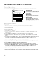
Setting up / replacing the PC-CARD
1. Set the projector into standby mode by pressing the main power switch. The POWER indicator
lights up red.
2. Open PC-CARD cover on the left side of the projector.
3. To replace the card, press the eject button to take the card out.
4. Insert the card, making sure the direction of the card is correct.
The PC CARD indicator will be illuminated.
5. Close the cover.
When the input source is set to PC1 or PC2, or during recording to the PC card, do not remove the
PC card. The projector may not work correctly.
Emergency capture from projector source
1. Set the projector into standby mode by pressing the main power switch.
2. Turn on the equipment connected to the projector.
3. Insert the card
4. Turn the projector on by pressing the POWER button on the top control panel.
5. Select the desired external input source by using the SOURCE button.
6. Press the CAPTURE button, when the desired image is selected for recording.
The image will freeze.
7. Press and hold the CAPTURE button for about three seconds before releasing.
The projector displays a blue screen and a time gauge appears.
• The recording takes about two minutes.
• When the recording ends, the blue screen will disappear.
• During recording, none of the buttons would operate.
• During recording, do not push any buttons on the control panel, remote control, or PCGC.
• When the image is not recorded correctly, the message “WRITE NG!” is appeared on the screen.
In case the above happens, delete the incomplete file using the PCV software to obtain the
memory storage capacity of the PC card.
• To record one picture, the memory storage capacity of 2.4 MB is necessary. Please check for
free space on the PCMCIA CARD before recording.
• When there is not enough capacity left in PC-CARD, the message "WRITE NG!" will appear on
the screen. In this case, turn the projector off and change PC-CARD.
• The picture modified by keystone cannot be recorded correctly. Please set the KEYSTONE to
0˚ before recording.
• We recommend to use the CAPTURE button on the remote control.
• When using the CAPTURE button on the control panel, the projector may record repeatedly. In
this case, press the
or
buttons on the control panel (or $ or % buttons on the remote
control) when the image is frozen. Then the unit will not record repeatedly.
8. To record another image, repeat steps 6 and 7.
Play back
1. Insert the prerecorded PC-card.
36
2. Press the MENU button once to display the on-screen menu.
3. Press the ª or º buttons on the control panel (or { or } buttons on the remote control) to
select OPTION.
4. Press the
or
CARD PLAY.
buttons on the control panel (or $ or % on the remote control) to select PC
5. Press the ª or º buttons on the control panel (or { or } buttons on the remote control) to
select MANUAL.
6. Press the MENU button to exit the menu system.
7. Press the SOURCE button repeatedly until PC-1 (or PC-2) appear on the screen.
The PC-CARD index display appears on the screen.
8. Press the ª , º,
or
buttons on the control panel (or { , } , $ or % buttons on the
remote control) to select the desired image.
• After pressing the FOCUS/ZOOM button, the ª or º buttons on the control panel (or { or
} buttons on the remote control) are worked for FOCUS or ZOOM adjustments. Pressing the
other button, the buttons worked for image selection.
• If the PC-CARD is recorded by using the personal computer, select the desired group by pressing the + or - button.
9. Press the º button on the control panel (or } button on the remote control) to enter the image
display mode.
10. Press the
or
buttons on the control panel (or $ or % buttons on the remote control) to
display another image.
11. Press the SOURCE button to quit the PC-CARD playback function.
• After pressing the FOCUS/ZOOM button, the ª or º buttons on the top control panel (or { or
} buttons on the remote control) would work for FOCUS or ZOOM adjustments. When ZOOM or
FOCUS disappears from the screen, the ª or º buttons wouldwork for image selection.
To automatically change the image, follow the steps as shown below.
1. Follow steps 1 to 4 from the previous instructions. (Select OPTION.)
2. Press the ª or º buttons on the control panel (or { or } buttons on the remote control) to
select USER and then press the ENTER button.
3. Set the PLAY GROUP, SLIDE TIME and REPEAT SLIDE. For more details of each items, see
page 31.
4. Press the
or
buttons on the control panel (or $ or % buttons on the remote control) to
select RETURN and then press the ENTER button.
5. Press the ª or º buttons on the control panel (or { or } buttons on the remote control) to
select AUTO.
6. Press the MENU button to exit the menu system.
7. Press the SOURCE button repeatedly until PC-1 (or PC-2) appear on the screen. The selected
image appears on the screen and the image automatically changes according your setting.
8. Press the SOURCE button to quit the PC-CARD playback function.
• The projector is able to playback only the PC-CARD recorded by the projector or PCV.
• When the ª , º,
or
buttons on the control panel (or {, }, $ or % buttons on the remote
control) or +, -, PinP or NATIVE buttons are pressed, the AUTO PLAY function will be cancelled.
• During auto play, the CAPTURE, ENTER, AUTO or EXPAND buttons cannot be operated.
• During PC-CARD playback, the sound is switched off.
• PC-CARD of the following manufacturers has been confirmed of operation;
EPSON, TDK, Logitec, Panasonic, Verbatim, I-O DATA
37
Advanced feature with PC
There are three types of application software provided.
1. PCV (PC Card Viewer)
2. PCGC (Personal Computer Graphic Controller)
3. SpacePointer (Driver for PC control by the remote controller)
Environment
The following system software and hardware are necessary to use the projector.
When you use Macintosh
PC
Macintosh series loading more than 68030 in CPU and a video card with
which more than 256 colors are available
System software
7.1 or newer
Note: You cannot use the PCV with Macintosh.
When you use Microsoft® Windows®
PC
Microsoft® Windows® Operating System Version 3.1 or newer with the CPU
loading more than 80386S and a display card with more than 256 colors are
available
System software
Microsoft® Windows® operating system Version 3.1 and the system software
that enables Windows® 3.1 to operate on your PC is needed.
EXPORT LAW ASSURANCES
You acknowledge and agree that the SOFTWARE is subject to restrictions and controls imposed by
the United States Export Administration Act (the “Act”) and the regulations thereunder. You agree
and certify that neither the SOFTWARE nor any direct product thereof is being or will be acquired,
shipped, transferred or reexported, directly or indirectly, into any country prohibited by the Act and
the regulations thereunder or will be used for any purpose prohibited by the same.
LIMITATIONS OF REMEDIES
Regardless of whether any remedy set forth herein fails of its essential purpose, in no event will
Mitsubishi be liable to you for any special, consequential, indirect or similar damages, including
any lost profits or lost data arising out of the use or inability to use the SOFTWARE or any data
supplied therewith even if Mitsubishi or anyone else has been advised of the possibility of such
damages, or for any claim by any other party.
Some states do not allow the limitation or exclusion of liability for incidental or consequential
damages so the above limitation or exclusion may not apply to you.
In no case shall Mitsubishi’s liability exceed the price for the SOFTWARE.
38
A.
PCV (PC Card Viewer)
PC-CARD viewer (PCV) is a utility software that lets you record and project an image to a PC-CARD
by using a personal computer.
Installation of software
1. Start up Microsoft® Windows®.
2. Insert the floppy disk labeled "PROJECTOR DRIVER (5/5) PCV (PC Card Viewer)" in the projector floppy disc drive.
If you use the Microsoft® Windows® 95 Operating System or a more recent version
3. Start up Program Manager.
Click the [Start] button and select the [Run (R)] command. Then the [Run] dialog box is displayed.
Move onto step 4.
If you use the Microsoft® Windows® Operating system Version 3.1 or a more recent version
3. Select the [Run (R)] command on the icon menu so that the dialog box [Run] is displayed.
4. If you inserted the floppy disk to drive A, type [A:\Setup] in the "command line" text box and click
the "OK" button. The letter [A] may be different according to the drive you use.
5. When the setup program starts up, follow the on-screen instructions.
6. When the message “Finished” appears on screen, click the [OK] button to complete the installation.
Starting up PC Card Viewer
1.
2.
Insert the PC card to the PC Card slot on the personal computer.
Double click the [PCV] icon to start up the PC Card Viewer.
Command reference
The command references are as shown below:
File
New presentation...
Create a new presentation.
Open presentation...
Open an existing presentation.
Close presentation...
Close the active presentation.
Save presentation...
Save the active presentation from the selected PC-CARD drive.
Delete presentation... Remove the active presentation from the selected PC-CARD drive.
Open image file...
Import an image from a Bitmap format file.
Exit
Quit the PC Card Viewer.
Edit
Cut
Remove the selected images of the active presentation and keep them
available to paste elsewhere.
Copy
Copy selected images from the active presentation for pasting elsewhere.
Paste
Paste the last image cut or copied to the clipboard into your current
presentation.
Capture...
Delete image...
Switch to the capture mode and open the capture dialog box.
Remove the selected image from the active presentation.
Tool
View
Tool Bar
Status Bar
Option
Select card drive...
Card drive Info...
Index image size...
Help
About PCV...
Display or hide the tool bar from the window.
Display or hide the status bar from the window.
Select (or change) the PC-CARD drive.
Display the information of the selected PC-CARD drive.
Select the size of index image.
Display the version of PCV.
39
Advanced feature with PC (continued)
Recording the image
When you wish to record the image of the display to a PC-CARD.
1. In the PCV main window choose [Select card drive...] under the [Option] menu and then choose
the PC-CARD drive.
2. Choose [New presentation...] under the [File] menu.
The new presentation window will open.
3. Choose [Capture...] under the [Tool] menu.
The PCV windows disappear and the capture dialog box appears.
4. Display the image you wish to record on the screen.
5. Click the capture button.
The Format setting window appears.
6. Select the Format, BMP or JPEG.
If you select JPEG, select the Quality.
You can confirm the compressed image by clicking the Preview
button.
Return button
Delay time button
Capture button
7. Click OK button.
8. Click the return button.
The presentation window will open. The recorded image appears on
the presentation window.
Depending on the personal computer, the recorded image can appear
incorrectly. In this case, set the delay time longer by using the Delay
time dialog box and repeat steps 5 to 7.
9. Repeat steps 4 to 8 for other images.
10. Choose [Save presentation...] under the [File] menu.
11. Choose [Exit] under the [File] menu to quit from PCV.
When you wish to record the image from existing files.
1. In the PCV main window choose [Select card drive...] under the [Option] menu and then choose
the PC-CARD drive.
2. Choose [New presentation...] under the [File] menu.
The new presentation window will open.
3. Choose [Open image file...] under the [File] menu.
The list box displays the names of the files.
4. Select the image you wish to record.
5. Click OK button.
6. The recorded image appears on the presentation window.
• The maximum number of images that can be recorded to a PC card is 160.
• The maximum number for the group (presentation) is 99.
• JPEG file cannot access.
40
7. Repeat steps 4 to 6 for other images.
8. Choose [Save presentation...] under the [File] menu.
9. Choose [Exit] under the [File] menu to quit from PCV.
Editing the presentation
Delete the image
1. Select the image to be deleted.
2. Choose [Delete image...] under the [File] menu.
Sequencing
A. Exchange images
You can exchange the images among images next to each other.
1. Select an image to be exchanged.
2. Drag the image and drop on the next or previous image.
B. Move images
You can move images to another position.
1. Select an image to be moved.
2. Drag the image and drop it on the other image (except next or
previous image).
The image will be moved to the previous position of the dropped
image.
Move images to another presentation file
You can move images to another presentation file.
1. Select an image to be moved.
2. Drag the image and drop on another presentation window.
The image will be moved to the last position of the dropped presentation.
• By using Cut, Copy & Paste, you can also edit the presentation.
Preview an image
1. Select an image to be previewed.
2. Double click the image.
The preview image appears on the displays.
Display image information
1. Click the image by using the right button of the mouse.
The image information window appears.
2. Choose OK to close the image information window.
41
Advanced feature with PC (continued)
B.
PCGC (Personal Computer Graphic Control)
By connecting to personal computer is RS-232C port, you can operate your computer with the projector remote control. Also you can set the menu setting of the projector by computer.
Connection
Control cable
• RS-232C cable (reverse)
• RS-232C adapter for Macintosh
• RS-232C adapter for NEC 98 series
Projector + IBM PC or IBM PC compatibles (DOS/V)
to RS-232C
terminal
to Com1
Comport
Note:
RS-232C cable
If your PC (IBM or IBM compatible) is equipped only with a 25-pin serial port connector,
a 25-pin serial port adapter is required. Contact your dealer for details.
Projector + Macintosh
to RS-232C terminal
to modem port
RS-232C adapter
for Macintosh
Note:
RS-232C cable
If the only serial port is a “modem/printer”, use it.
Projector + NEC PC 98 and EPSON series
to RS-232C terminal
to RS-232C terminal
RS-232C
adapter for NEC
(option)
42
RS-232C cable
Installation of software
For Macintosh
1. Insert the floppy disk of "PROJECTOR DRIVER (2/5) PCGC (Mac)" to the floppy disk drive.
2. Copy "PCGC” folder to anywhere on the hard disk.
For Microsoft® Windows®
1. Start up Microsoft® Windows®.
2. Insert the floppy disk labeled "PROJECTOR DRIVER (1/5) PCGC (Win)" to the floppy disk drive.
If you use the Microsoft® Windows® 95 Operating System or a more recent version
3. Click the [Start] button and select the [Run (R)] command. Then the [Run] dialog box is displayed. Move onto step 4.
If you use the Microsoft® Windows® Operating system Version 3.1
3. Select the [Run (R)] command on the icon menu so that the dialog box [Run] dialog box is displayed.
4. If you insert the floppy disk to drive A, type [A:\Setup] in the "command line" text box and click
the "OK" button. The letter [A] may be different according to the drive you use.
5. When the setup program starts up, follow the on-screen instructions.
6. When the message “Finished” appears on screen, click the [OK] button to complete the installation.
Starting up PCGC
Double click the [PCGC] icon in the setup folder to start up PCGC.
• Do not use SpacePointer during the PCGC operation.
A. Indicator and main menu control window
PCGC
File
Power button and indicator
Use to turn the projector on or off
when MAIN POWER is on. When in
standby mode, this indicator lights
up red. When the projector is fully
“ON”, the button lights up green.
Window
LAMP
Help
TEMP
CARD1
CARD2
VIDEO1
NORMAL
VIDEO2
ENHANCED
RGB1
RGB2
PC1
PC2
POINTER
AUDIO
OPTION
QUIT
Input selector
Click to select an input source.
The input sources are; VIDEO1, VIDEO2, RGB1, RGB2, PC1
and PC2. You can only select PC1 or PC2 when the PC card is
inserted in the projector.
Indicators
(Same as on the projector. See pages 8 and 9.)
• Each indicator may
not match the one of
those on the control
panel.
Main MENU selector
Click to select sub menu.
The sub menus are
NORMAL, ENHANCED,
POINTER, AUDIO and
OPTION. To quit this
software click QUIT.
43
Advanced feature with PC (continued)
B. Sub menu control window
The window is changed according to the selected position of the main menu selection.
PCGC
CONTRAST
BRIGHTNESS
0
0
R/G/B
TINT
COLOR
0
0
R/G/B
GAMMA CORRECTION
USER
RESET
C. Remote control window
Remote
FOCUS/ZOOM
FRAME
ENTER
REAL
PinP
CAPTURE
AUTO
Note:
• When you operate the PCGC, do not use SpacePointer.
• Make sure proper connection shave been made, or else the PCGC will not start up.
• When you operate the PCGC, switch off the menu display on the projector.
When you operate the PCGC, be sure not to press any buttons on the control panel on the projector (except the POWER button).
Caution:
• Mitsubishi is not responsible for any complications caused by the use of this PCGC software.
For improvement, Mitsubishi Electric America reserves the right to change or alter any or all
specification or design of this remote control and the content of the owner's guide without any
prior notice.
• No part of this software and owner's guide may be reproduced, transmitted, transcribed, stored in
a retrieval system, or translated into any language in any form by any means. Otherwise, this
will be considered as a copyright infringement.
44
C.
SpacePointer
The remote control provides remote PC operation for presentation from PC. (Space pointer)
Connection
The connection is the same as for PCGC. Refer to page 42.
Installation of software
For Macintosh
1. Insert the floppy disk of "PROJECTOR DRIVER (4/5) POINTER DRIVER (Mac)" to the floppy
disk drive.
2. Copy "Space pointer" in the “US” folder to the system folder.
3. Restart the Macintosh.
For Microsoft® Windows®
1. Start up Microsoft® Windows®.
2. Insert the floppy disk labeled "PROJECTOR DRIVER (3/5) POINTER DRIVER (Win)" to the
floppy disk drive.
If you use the Microsoft® Windows® 95 Operating System or a more recent version
3. Click the [Start] button and select the [Run (R)] command. Then the [Run] dialog box is displayed.
4. If you insert the floppy disk to drive A, type [A:\win95\Setup] in the "command line" text box and
click the "OK" button. The letter [A] may be different according to the drive you use.
5. When the setup program starts up, follow the on-screen instructions.
6. When the message “Finished” appears on screen, click the [OK] button to complete the installation.
If you use the Microsoft® Windows® Operating system Version 3.1
3. Select the [Run (R)] command on the icon menu so that the dialog box [Run] is displayed.
4. If you insert the floppy disk to drive A, type [A:\win31\Install] in the "command line" text box
and click the "OK" button. The letter [A] may be different according to the drive you use.
5. Select the [Installation (I)] command on the installation menu.
6. When the setup program starts up, follow the on-screen instructions.
7. When the message “Finished” appears on screen, click the [OK] button to complete the installation.
Operation of PC by remote control
The remote control provides remote PC operation for presentation from PC.
1. Press the SOURCE button to select RGB1 or RGB2.
2. Press the START/STOP button to ON.
The operation indicator will be illuminated.
3. Confirm that the cursor of the projector does not appear on the screen. If the cursor does appear,
press the CURSOR button to OFF.
You can use the SELECT, CANCEL and DOUBLE CLICK button in the same way as the button
on the mouse. You can also move the cursor of PC by using the remote control. For cursor moving,
see page 13.
4. Press the START/STOP button to exit from PC control mode.
45
Advanced feature with PC (Continued)
Setting of SpacePointer
You can set the several settings in the Space Pointer control panel in the control panel folder.
SpacePointer
SpacePointer
Enable/Disable
For normal use set to Enable. If you do
not use SpacePointer, set to Disable.
®
Enable/Disable
Enable
ReceiverCheck
ON
ConnectPort
COM1
COM2
Disable
OFF
COM3
SLOW
COM4
FAST
Help
Apply
OK
Cancel
Unselectable
Port selection
Used to select the port connected to
the projector.
Tracking speed
If you click Fast, the cursor moves
more than twice as fast as you move
the space pointer. When you first try
the remote control, set it to slow.
Uninstallation of software
For Macintosh
1. Move "Space pointer" in the control panel folder in the system folder to “Trash”.
2. Restart the Macintosh.
For Microsoft® Windows®
1. Start up Microsoft® Windows®.
2. Insert the floppy disk labeled "PROJECTOR DRIVER (3/5) POINTER DRIVER (Win)" to the
floppy disk drive.
If you use the Microsoft® Windows® 95 Operating System or a more recent version
3. Click the [Start] button and select the [Run (R)] command. Then the [Run] dialog box is displayed.
4. If you insert the floppy disk to drive A, type [A:\win95\Spuninst] in the "command line" text box
and click the "OK" button. The letter [A] may be different according to the drive you use.
5. When the setup program starts up, follow the on-screen instructions.
6. When the message “Finished” appears on screen, click the [OK] button to complete the installation.
If you use the Microsoft® Windows® Operating system Version 3.1
3. Select the [Run (R)] command on the icon menu so that the dialog box [Run] is displayed.
4. If you insert the floppy disk to drive A, type [A:\win31\Install] in the "command line" text box
and click the "OK" button. The letter [A] may be different according to the drive you use.
5. Select the [Uninstallation (U)] command on the installation menu.
6. When the setup program starts up, follow the on-screen instructions.
7. When the message “Finished” appears on screen, click the [OK] button to complete the installation.
46
Maintenance
Caution:
Be sure to turn off the projector and unplug the power cord from the wall outlet before you perform
any maintenance on the projector.
Cleaning the air-filter
Clean the air-filter frequently. If the filter or ventilation slots become clogged with dirt or dust, the
temperature inside of the projector may rise and shut of the power (the thermal indicator starts to
blink red).
1. Press and raise the air-filter cover with a screwdriver
(-).
2. Wash the air-filter.
Use water or a mild detergent diluted with water to clean the filter. Rinse the filter thoroughly
and let it dry completely. If the filter is damaged or becomes extremely dirty, contact your dealer
for replacement information.
3. Attach the air filter to the cover.
FILTER
4. Reinstall the air-filter cover.
FILTER COVER
Note: The power will notturn on if the air-filter cover is improperly installed.
Caution:
Be sure to use the projector with an air-filter. If not, dust may get inside the projector, causing a fire
or a breakdown.
Cleaning the projector and the ventilation slots
Use a soft cloth to clean the projector and the ventilation slots. When the slots become dirty, wipe
them with a soft cloth dampened with a diluted mild detergent, and then wipe them with a dry cloth.
To protect the surface of the projector from fading or deteriorating:
• Do not spray insecticide on or inside the projector.
• Do not use benzine or thinner to clean it.
• Do not let rubber or plastic materials come into contact with the projector.
Cleaning the lens
Use a standard lens-cleaning brush or a piece of lens tissue dampened with lens cleaning fluid. The
lens surface is fragile. Use only recommended, nonabrasive lens-cleaning materials. Do not touch the
lens with your fingers.
47
Replacement of a light source lamp
The light source lamp is designed to project the image on the LCD panel. When the light source lamp
no longer functions, replace it with a new one to ensure optimum performance.
Caution:
• Do not remove the light source lamp from inside of this equipment immediately after using the
projector, you may get burned because of the high temperature of the light source lamp.
• When you replace the light source lamp, press the power button to power off, then wait for 120
seconds in stand-by mode to cool down the lamp and LCD panels. Turn off the main switch,
unplug the power code from the outlet and wait one hour so that the lamp is cool to the touch.
• Do not remove the light source lamp except for replacement. Careless treatment can cause injury
or fire.
• Do not touch the lamp directly. It may be broken and may cause you to injure or burn yourself.
• Be sure not to drop the lamp lid screw into the projector. Also be sure also not to insert metal or
any flammable objects, it may cause fire or an electric shock. If any objects are inserted, please
unplug and contact your dealer.
• Install the lamp securely, failure to do so it may cause a fire.
Loosen here
1. Loosen the screw of the lamp lid on the top cover using a
screw driver(-) or a coin, and remove the lid.
Important:
Be careful not to damage the electric wire connected to
this equipment.
2. Use a screwdriver (+) to loosen the two lamp screws.
Use a soft cloth to cover the lamp.
Screws of the lamp
3. Hold onto the projector by the handle as your pull out the
lamp.
Caution:
For the lamp you have removed, do not spill liquid on it,
place it near flammable objects or where children can touch
it. Otherwise, it will cause injury or fire.
Handle
48
4. Hold onto the projector by the handle and insert it securely
into the projector body.
• Be sure that the projector guide is firmly inserted between
the right and left lamp guides.
Do not touch the lamp directly, place a cloth over the
replacement lamp.
Important:
• Replace with same type lamp rated.
• Avoid squeezing the light sources lamp or getting
finger prints on it. Mishandling the lamp can shorten the lamp life, cause it to burst during
operation or reduce its illumination.
5. Tighten up the two screws of the lamp using a screwdriver (+).
6. Tighten up the screw of the lamp lid using a screwdriver (-) or a coin.
Important:
The projector will not turn on if you do not secure the lamp lid.
7. Plug in the power cord, switch on the projector and reset lamp time by pressing the
POWER buttons simultaneously.
,
and
Purchase of the light source lamp
The expected life of the metal halide light source lamp is 1,300 hours. However, to maintain optimum performance, it is recommended that the light source lamp be replaced at 1,000 hour intervals.
When the lamp no longer works well, replace it with a new one specified for this projector. Consult
your dealer, for recommended replacement lamps.
The life of the lamp
The average life of the lamp for the projector is about 1,300 hours of consecutive use. The lamp
indicator will blink in red after approximately 1,000 hours. When the lamp has been used for about
1,200 hours, the message “PLEASE CHANGE THE LAMP.” will appear on the screen. When the
lamp has been used for about 1,300 hours, the projector will automatically shut off for the safety of
the lamp and the power indicator light up in red. The projector cannot be used until the lamp has
been replaced.
Caution:
• The light source lamp is fragile. Be careful not to cut yourself with the fragments.
• The lamp life depends on the environment. For replacement lamps, please contact your dealer.
The projector automatically shuts off when the lamp is used up in about
1,300 hours and not used until lamp replacement.
49
Indicators / TEMP, LAMP, POWER
The projector has three indicators each of which shows the working condition of the projector.
• Though the LAMP and TEMP indicators are on the main menu control window of PCGC, the each
indicator may not match the one of those on the control panel.
LAMP TEMP
FREEZE
SOURCE /CAPTURE
The following offers solutions to possible problems. If a problem persists, turn the projector off
and consult your dealer.
INDICATOR
TEMP
INDICATOR
SHOWS
blinking red
CONDITION
• Unusual temperature
The power is turned off
and the POWER indicator
lights up red.
• The ventilation slots or air
filter is clogged with dust
or debris.
• The fan has stopped due
to an impediment.
• The location temperature
is too high.
• The filter is dirty.
LAMP
INDICATOR
Steady green
Normal
Blinking red
Lamp is almost used up.
Steady red
• Lamp is used up.
• The power is not turned on.
(Power indicator lights up red.)
POWER
INDICATOR
50
POSSIBLE SOLUTIONS
• Remove the object from
the ventilation slot.
• Pull out the power
plug and remove the
object. If you cannot,
consult your dealer.
• Relocate the projector
to a cooler place.
• Clean the filter.
Replace the lamp.
Exchange with a new
lamp if the same
problem recurs.
Steady red
Standby
-
Steady green
Power-on
-
Troubleshooting
The following offers solutions to some of the common problems you may encounter. We suggest that
you consult this chart before contacting your dealer.
PROBLEMS
CAUSE
• The air intake vents, exhaust vents
or air filter is clogged with dust or
some object.
The power is off.
Power indicator does not light up.
• Power cord is unplugged from the
outlet.
• Power cord is disconnected from the
projector.
• The main switch is turned off.
• The lamp lid is open.
Power indicator blinks red.
• The projector has been turned on
again too soon after having been
turned off.
• The room temperature is too high.
(Does the lamp indicator show an
unusual condition?)
•The filter cover is not closed.
No picture appears
on the screen.
The image is
distorted.
POSSIBLE SOLUTIONS
• Remove the object.
• Plug the power cord into the outlet.
• Insert the power cord into the projector.
See page 15.
• Turn the main switch on.
• Close the lamp lid.
• Wait for the lighting sequence.
• Refer to "INDICATORS" on page 49.
• Close the cover correctly.
• Lens is covered by lens cap.
• Lamp is no longer working.
• Take the lens cap off.
• Replace the lamp with a new one.
• The equipment connected to this projector is not turned on.
• Hookup is not made correctly with
other equipment.
• The input source is not selected correctly.
• Turn on the connected equipment.
• The projector is not at a right angle to
the screen.
• Adjust the angle of the projector to make a
right angle to the screen. See page 15.
• Confirm the hookup.
• Select the correct source according to the
equipment connected to this projector.
The image is
dark.
• Brightness, tint and color are not • Adjust brightness, tint and color correctly.
adjusted correctly.
The image is
blurred.
• The projecting distance is beyond the
focused area.
• Lens is dirty.
• Brightness, contrast and DLE are not
adjusted correctly.
• FINE adjustment is not made correctly.
• Tracking is not adjusted.
• The projector is not at a right angle to
the screen.
• Adjust the projecting distance. See page 14.
• Clean lens.
• Adjust brightness, contrast.
• Make FINE adjustment.
• Adjust tracking.
• Adjust the angle of the projector to make a
right angle to the screen. See page 15.
51
PROBLEMS
CAUSE
POSSIBLE SOLUTIONS
The image
remains blurred.
• When you see the stationary image for a long time, it may remain on the screen if
you change the image. It is not a breakdown. The blurred image will disappear in a
few minutes.
Red, blue or green
dots are viewed on
the text of image.
• It is normal.
The image is
distorted on the
screen and
noise is heard.
• The cable for connection with other
equipment is not plugged securely
into the terminal.
• The projector is installed too close to
other equipment.
• Plug the connecting cable securely into the
terminal. See pages 17-21.
• Volume is not turned up.
• Mute function on PCGC is on.
• Turn up the volume.
• Cancel the mute function. See page 30.
• Connection to other equipment is not
made correctly.
• Check connections.
See page 21.
• The PC monitor is not turned on.
• Turn on the monitor.
No sound is
heard.
Nothing is
displayed on
the PC monitor.
• Install the projector far away from other
equipment.
Warm air comes out • This is typical of the LCD projector.
of the exhaust vents.
Adjustments cannot • The operation is incorrectly made due • Reset the mode and try again.
to noise or interference.
be made.
52
Specifications
Type
LCD projector
Model
LVP-X100A
Rated power supply
AC100 ~ 240V, 50 / 60Hz
Rated input
5.0A
LCD panels
1.3-inch LCD panel: 3 pieces (for R, G, B)
Pixels
1,024 × 768 = 786,432 pixels
Total 2,359,296 pixels
Active pixel rate: 99.99 % or more (each panel)
Projection lens
F 2.5~2.9
Light source lamp
280 W DC metal halide lamp
Picture size
aspect ratio 4:3 20~300 inch
Audio output
1 W + 1 W stereo
Speakers
6 cm round type (8Ω 1W) × 2 pcs.
S-video input
Luminance signal: 1.0 Vp-p 75Ω (negative sync.)
Chroma signal: 0.286 Vp-p 75Ω (burst signal)
Video input
1.0 Vp-p 75Ω (negative sync.)
Audio inputs
350 mVrms, 10kΩ or more
Analog RGB input
(mini D-SUB 15P)
PC audio inputs
f = 52.8 ~ 68.6 mm
RGB: 0.7Vp-p 75Ω (positive sync.)
YCbCr: Y:1.0Vp-p (negative sync.) Cb, Cr:0.7Vp-p
HD/CS : TTL level (positive)
VD : TTL level (positive)
350 mVrms, 10kΩ or more ø3.5mm stereo mini jack
Outside dimensions
330 × 145 × 385 mm
(width × height × depth)
Weight
21.5 lb (9.8kg)
Length of power code
70.8 inch (1.8m)
Temperature, humidity
(performance guarantee)
+41°F (+5°C) ~ +95°F (+35°C), 30~90%
Legs and lenses are not included.
53
Replacement parts list
What’s included in the box
1
1
1
1
1
1
1
1
1
1
1
1
1
1
AC power cable
RCA video cable
RCA/BNC adaptor
Audio cable
RGB cable for PC
MAC adaptor for RGB cable
RS-232C cable
MAC adaptor for RS-232C cable
Remote control
Lens cap
Warranty card
User‘s manual
Software disc set
Battery for remote
246C284-10
246C323-10
452D173-10
242C938-10
246C318-10
246C319-10
246C320-10
246C321-10
939P700-10
499B009-20
854B244-30
871D237-20
919P033-10
–
Accessories
1 Spare metal halide lamp
1 PC audio cable
54
499B011-10
242D493-10
MITSUBISHI ELECTRONICS AMERICA, INC.
5665 Plaza Drive
Cypress, CA 90630
871D237D2
Printed in Japan
55