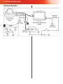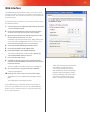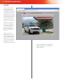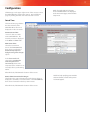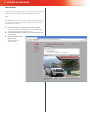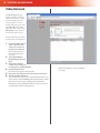
1
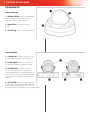
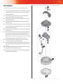
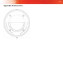
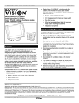
High Definition Stop Arm Camera System
SAFESTOP-HD User Guide
Important Notices
Title: SAFESTOP-HD User Guide
Firmware Version 5.40.9
Document Version 1.3
Safety Vision attempts to provide information contained in
this manual based on the latest product information available
at the time of publication. However, because of Safety Vision’s
policy of continual product improvement, Safety Vision
reserves the right to amend the information in this document
at any time without prior notice.
This material is confidential and the property of Safety Vision.
It is shared with your company for the sole purpose of helping
you with the operation of the described equipment.
Safety Vision makes no warranty of any kind with regard to this
material, including, but not limited to, the implied warranties
of merchantability and fitness for a particular purpose. Safety
Vision shall not be liable for errors contained herein or for
incidental or consequential damages in connection with the
furnishing, performance, or use of this material.
Safety Vision expressly disclaims all responsibility and liability
for the installation, use, performance, maintenance, and
support of third-party products. Customers are advised to
make their independent evaluation of such products.
No part of this document may be photocopied, reproduced,
or translated to another language without the prior written
consent of Safety Vision.
Safety Vision® is a registered trademark of Safety Vision, LLC. All
other products or name brands mentioned in this document are
trademarks of their respective
owners. For more information about Safety Vision and its
products, go to www.safetyvision.com or call 800-880-8855.
1
Components
Table of Contents
External Housing
Camera Module
2
2
2
Installation
Wiring Schematic
Web Interface
3
4
5
Configuration
7
Video Retrieval
Video Playback
10
11
Appendix A: Specifications
Appendix B: Dimensions
12
13
Live View
Date & Time
Focus & Zoom
6
7
8
2 SAFESTOP-HD User Guide
Components
External Housing
1 - Weather Shield - Protects the SAFESTOPHD from adverse weather conditions, tree
branches, and other outdoor hazards.
2 - Dome Cover - Protects the camera
module.
3 - Unit Casing - Houses the camera module.
Camera Module
1 - Camera Lens - Captures images. Can be
rotated 45 degrees when mounted sideways.
2 - I/O Connector - Receives a signal when
the stop arm is extended to begin recording.
3 - LAN Ethernet - Connects to a Power
over Ethernet (PoE) Injector to supply power
to the SAFESTOP-HD. Use an Ethernet cable to
connected to a PC to access the SAFESTOP-HD’s
web interface (see the Web Interface chapter on
page 5).
4 - SD Card Slot - Houses a pre-formatted SD
card for storing recorded video. Recorded video
is accessed through the Web Interface. There is
no need to remove the SD card from the camera module.
3
Installation
Use the following procedure to install the SAFESTOP-HD.
1. Using the included template, tap or otherwise mark the
screw holes and passage for the cables in the desired
mounting location.
2. Use self-tapping screws or rivets to secure the base
plate to the desired mounting location.
3. Connect the cable assembly to the I/O Connector and
LAN Ethernet ports.
4. Thread the cables through the base plate and drilled
cable passage.
5. Insert the camera module into the unit casing, ensuring
it is secure in the spring steel bracket, and secure it with
the two provided screws.
6. Place the unit casing with secured camera module onto
the base plate.
7. Loosen the security screws on the camera gimbal to adjust the camera angle to the desired field of view. This
might require the use of a PC connected to the Web
Interface (see the Web Interface chapter on page 5). Once
completed, tighten the security screws in place.
8. Place the dome cover over the base unit so that the
view of the camera is not obstructed.
9. Place the weather shield over the dome cover and secure the entire assembly with the four included security
screws.
10. Connect to the Web Interface and perform the focusing
procedure as described on page 8.
11. Consult the wiring schematic on the following page to
complete the installation.
4 SAFESTOP-HD User Guide
Wiring Schematic
5
Web Interface
The SAFESTOP-HD web interface includes a live camera view,
configuration and focus options, and allows recorded video to
be downloaded. The web interface must be accessed with a PC
and web browser.
Use the following procedure to access the web interface using
the default IP address:
1. Connect the PC to the SAFESTOP-HD’s Ethernet port with
a standard Ethernet cable.
2. Ensure the SAFESTOP-HD and PC are receiving power
and have started up (this may take a few seconds).
3. Open the Internet Protocol (TCP/IP) Properties window
for the LAN connection you are using.
In Windows, open Network Connections. Right-click the LAN
connection and select Properties. In the list of items, select
Internet Protocol (TCP/IP) and then click Properties.
4. Select the Use the following IP address option.
5. Enter 192.168.8.80 in the IP address field.
6. Enter 255.255.0.0 in the Subnet mask field.
This field normally defaults to 255.255.255.0. Ensure the
correct 255.255.0.0 subnet is entered.
7. Leave all other fields blank.
8. Click OK on the Internet Protocol (TCP/IP) Properties
window and then click OK on the Local Area Connection
Properties window.
Your PC’s IP address and subnet mask are now configured.
9. On a web browser, navigate to 192.168.8.70/local.
A Login prompt appears.
10. Enter the user name and password and click Login.
The default user name is root and the default password is
pass.
The configuration web interface launches.
Access different pages of the web interface by clicking on
the links on the left side of the screen. The SAFESTOP-HD’s
firmware version and MAC address are displayed below the
basic setup instructions.
NOTE: Steps 9 and 10 can be automated
with a link on your desktop. Go to
www.safetyvisionftp.com/software
and download the shortcut installation
program. Run this program to install a
link on your desktop. This link will open
your browser, navigate to the correct
address, and log in, all automatically.
6 SAFESTOP-HD User Guide
Live View
The Live View provides
a live image from the
camera, for the purposes
of adjusting the angle and
checking that the image
is unobstructed. The Live
View screen appears when
you first log in. It can also
be accessed by clicking
Live View on the upper
right corner of the screen.
The video compression
level can be selected in
the Stream profile field.
(This controls the Live
View screen only, and
does not configure the
camera.)
Click the icons in the
View size field to select
between a full size image
or one restricted to 800
pixels wide. The video
stream can be stopped by
clicking the Stop icon on
the lower left of the screen.
NOTE: Selecting different stream profiles
may prompt your browser to download
additional plugins.
7
Configuration
Click Manage on the upper right corner of the screen to access
the SAFESTOP-HD’s configuration menus. Access different
pages by clicking the links on the left side of the screen.
NOTE: The SAFESTOP-HD’s firmware
version and MAC address are displayed
on the Instructions page, under the Basic
Setup menu.
Date & Time
The Date & Time page defines
the date and time of the
SAFESTOP-HD and how it is
displayed on video it records.
Current Server Time
“Server” in this case refers
to the SAFESTOP-HD. The
currently set time is displayed
in the Date and Time fields.
New Server Time
Select the current time
zone in the Time zone field,
then select or unselect the
Automatically adjust for
daylight saving time changes
option.
In the Time mode field,
select either Synchronize
with computer time or
Set manually. Ensure the
computer’s date and time is set
correctly before synchronizing
with it.
When finished, click Save at the bottom of the screen.
Date & Time Format Used in Images
The fields in this section determine how the date and time is
displayed as metadata on recorded video. Select Predefined,
then select a format from the drop-down menus.
When finished, click Save at the bottom of the screen.
NOTE: For help specifying your own date
and time formats, contact Safety Vision
Technical Support.
8 SAFESTOP-HD User Guide
Focus & Zoom
The Focus & Zoom page provides an easy method to properly
adjust the focus and zoom of the SAFESTOP-HD’s camera.
Basic
The Basic tab provides a quick and simple method of focusing
the camera. Use the following procedure to focus the camera
using the Basic method:
1. Ensure the image is correctly aligned and centered.
2.
3.
Remove the weather shield and dome cover and adjust the
camera’s position until the image is correct.
Use the Zoom slider until the focus is on the correct part
of the image.
Click the Perform auto
focus button.
The camera focuses
automatically.
9
Advanced
The Advanced tab allows
access to a more advanced
focusing method involving
the camera’s iris. Using the
Advanced focus procedure
may allow the camera to
more accurately adjust to
varied lighting conditions
encountered on bus routes.
Use the following procedure
to focus the camera using the
Advanced method:
1. Ensure the image is
2.
3.
4.
5.
correctly aligned and
centered.
Remove the weather shield
and dome cover and adjust
the camera’s position until
the image is correct.
Click the Open iris
button.
Use the Focus position
slider until the focus is
on the correct part of the
image.
Click the Perform auto
focus button.
The camera focuses automatically.
Click the Enable iris button.
10 SAFESTOP-HD User Guide
Video Retrieval
The Recording List page
displays available recorded
video and provides a means
for downloading it to the
connected PC. To access
the Recording List page, first
click Manage in the upper
right side of the screen, then
Recordings in the menu on
the left side of the screen.
Use the following procedure
to download recorded video:
1. Under the Filter section,
2.
3.
4.
5.
6.
select a time that the
video was recorded in
the From and To fields.
Enter a date and time in
the displayed format if
necessary.
Select Ascending or
Descending in the Sort
field.
Select the maximum
number of recordings to
be displayed in the Results field.
Click the Filter button.
Recorded video segments appear below.
Select the recordings you want to download to the PC.
Click the Download button.
The selected video segments are automatically placed in a singular .zip file entitled recordings.zip and downloaded. Follow
your browser’s instructions regarding downloading files.
Alternatively, click the Remove button to delete the selected
recorded video off of the SAFESTOP-HD.
NOTE: “Bus Stopped” is the only available
event type.
11
Video Playback
Video is downloaded from the SAFESTOP-HD in a compressed
.zip file. Use your preferred file compression software to
uncompress or unzip the file. Safety Vision recommends
WinRAR.
Individual video files within the .zip file have a .safestop file
extension. Safety Vision recommends a multi-format media
player, such as VLC media player, to view these videos.
WinRAR and VLC media player are both available free. Links
to download these programs can be found at http://www.
safetyvisionftp.com/software.
12 SAFESTOP-HD User Guide
Appendix A: Specifications
SPECIFICATIONS
Image Sensor
Progressive scan RGB CMOS 1/3” (effective)
Minimum Illumination Color: 0.5 lux, F1.2, B/W: 0.08 lux, F1.2
Shutter Time
Automatic
Video Compressions
H.264 (MPEG-4 Part 10/AVC) Motion JPEG
Resolutions
1920x1080 (1080p) to 160x90
Supported Protocols
IPv4 and HTTP
Casing
Polycarbonate transparent cover, aluminum inner camera
module with encapsulated electronics, IP66- and NEMA 4Xrated, IK10 impact-resistant aluminum casing with integrated
dehumidifying membrane
Connections
RJ-45 10BASE-T/100BASE-TX PoE, terminal block for 1 alarm input
Recording
10-second pre-event, 1-second post event automatic upon stop
arm deployment
Storage
SD/SDHC memory card slot
Operating Conditions
Temperature: -40 °C to 55 °C (-40°F to 131°F)
Humidity
15 - 100% RH (condensing)
Dimensions (dia x h)
7in. x 4.6in. (without weather shield)
7in. x 4.8in. (with weather shield)
13
Appendix B: Dimensions
SAFESTOP-HD User Guide
Limited 5-Year New Product Warranty
Safety Vision, LLC (“SV”) makes the following limited warranty,
which is effective at the time of the original end-user
purchase.
Note: Optional warranty products are available for all SV
products and may be purchased at the time of the original enduser purchase or any time during the original Limited 5-Year New
Product Warranty period.
SV warrants this product against defects in materials for
a period of 5 year after the date of purchase. During this
period, SV will repair or replace a defective product or part
without charge to the customer. The customer must send the
defective product or part to SV or an authorized SV dealer.
The customer must pay for all transportation and insurance
charges for sending the unit to be repaired. SV’s total liability
is limited to the original product cost.
User Guide
The customer should thoroughly read this guide before
operating this product.
Customer’s Responsibility
The above warranty is subject to the following conditions:
• Customer must notify SV within 10 days of discovering
the defective product or part and provide a description of
the defect and complete information about the manner
of its discovery.
• All warranty servicing of this product must be performed
by SV or an authorized servicing agent.
• Warranty extends only to defects in materials as limited
above. Warranty does not extend to any product or
part that has been lost or discarded by the customer; to
damage to products or parts caused by misuse, accident,
improper installation, improper maintenance, or use
in violation of instructions furnished with the product;
to units that have been altered or modified without
authorization of SV; to damage to products or parts
thereof that have had the serial number removed, altered,
defaced, or rendered illegible; or to any failure of the
product to function caused by burglary, fire, flood, war,
riot, civil commotion, Acts of God, or any other condition
beyond the control of SV.
Obtaining Warranty Service
To obtain warranty service, the customer must contact
the SV Service and Warranty Manager at 713.896.6600 or
800.880.8855 to report a defective product. (The customer
must report the model number and serial number if
available.) The Service and Warranty Manager will assist in
troubleshooting the problem and, if necessary, issue a return
material authorization (RMA) number. The customer must
include this number on the outside of each package shipped
to SV.
Important Packing and Shipping Instructions
When a product requires service, only the affected component
must be returned. If returning the SAFESTOP-HD unit, please
include the SD card and HDD that was in use at the time the
issue occured. The customer must use proper packing material
to ensure against damage during shipping. Any shipping
damage caused by improper packing is not covered under
this warranty. In addition, the customer must include a return
material authorization (RMA) number on the outside of each
package shipped to SV and a letter explaining the defect with
the product.
FCC Compliance Statement
NOTE
This device has been tested and found to comply with the limits
for a Class B computing device, pursuant to subpart B of part 15 of
the FCC Rules. These limits are designed to provide reasonable
protection against harmful interference when the equipment
is operated in a commercial environment. Operation of this
equipment in a residential area is likely to cause interference,
in which case the user at his/her own expense will be required
to take whatever measures may be required to correct the
interference.
CAUTION
Any changes or modifications in construction of this device
which are not expressly approved by the party responsible for
the compliance could void the user’s authority to operate the
equipment.
15
Corporate Headquarters
6100 W. Sam Houston Pkwy. N.
Houston, TX 77041-5113
Toll Free: 800.880.8855
Main: 713.896.6600
Fax: 713.896.6640
www.safetyvision.com
Copyright © 2012 Safety Vision, LLC. All Rights Reserved.
9/12