1
D X - 8 0
Installation & Maintenance Manual
C O M D I A L
DX-80TM
Every effort has been made to assure the accuracy of the information in this document. The
manufacturer assumes no responsibility, express or implied, for errors or omissions.
© Copyright 2001
Information in product documentation is subject to change without notice and does not represent
a commitment on the part of Comdial®. No part of Comdial® manuals may be reproduced or
transmitted in any form or by any means, electronic or mechanical, including photocopying, for
any purpose other than the purchaser's personal use, without the written permission of Comdial®.
Products mentioned in this documentation that are not manufactured by Comdial® may be
trademarks or registered trademarks of their respective manufacturers.
© Copyright Comdial®, 2001.
All rights reserved.
DX-80 INSTALLATION AND MAINTENANCE MANUAL
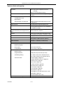
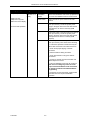
REVISION HISTORY
Version
03/01
05/01-1
Changes
Date
Initial version
03-28-2001
Formatting corrections:
05-10-2001
Tables in Overview chapter
Diagram layout in Installation chapter
PC-DBA screens in Maintenance chapter
Feature code corrections:
Alarm Clock – Extension
Attendant / Extension DSS Console Button Programming
Automatic Redial
Automatic Selection (CO/Intercom)
Call Forward – Extension
Database Administration – Via Any Digital Extension
Flash – CO Line
Flash – PBX Line
Memo Pad
Page Allow / Deny
Pause / Pause Insertion
Voice Mail – Analog Integration
Voice Mail – Digital Integration (optional)
Changes in Features chapter:
Account Code – Voluntary / Forced / Verified (Related Features and
Default Setting sections)
Conference, Supervised/Unsupervised (Programming via PC-DBA
section)
Enhanced Lettering Scheme (Related Features section)
UCD Agent Log Off/Log On (Operation section)
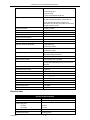
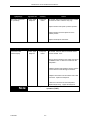
08/01-1
Addition of index entries for DSU II features
Feature code corrections:
Automatic Record
Busy Forward
External Call Forward
Changes in Features chapter:
Addition of Analog Ports (Single Line Telephones) information
Account Code – Voluntary / Forced / Verified (Programming via the
DET section)
Alarm Clock – Extension (Operation sections: Activate, Deactivate)
Answering Machine Emulation (Programming via PC-DBA section: VM
Monitor Time range added)
Attendant (Conditions section: default Extension User Password added)
Attendant / Extension DSS Console (Programming via the DET section;
Programming via PC-DBA section: default Attendant extension User
Password added)
Automated Attendant (Operation – Setup section: default Tenant Group
password added)
Automatic Hold (Operation – Cancel section)
Automatic Redial (Programming via the DET section – Attempts range)
Call Forward – Extension (Operation – Setup section: External Call
Forward)
CO Line Ring Assignment (Answer Position) – (Programming via the
DET section: Program CO Lines for Day Ringing Assignment)
Direct Inward Station Access (Operation section)
Do Not Disturb – Override (feature description and Related Features
section)
Feature / Directory Number Lookup (Operation section: addition of
Disable Codes)
Flexible Feature Button Programming (Operation section)
Night Service Mode / Activate (feature description)
P7290 IMM
RH-1
08-14-2001
DX-80 INSTALLATION AND MAINTENANCE MANUAL
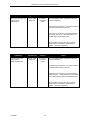
Version
Changes
Speed Dial – Extension/System (Programming via the DET section)
System Time and Date (Programming Abstract section)
Toll Restriction – Class of Service (Programming via the DET section)
UCD Agent Log Off/Log On (Conditions section deleted)
Voice Mail – Analog Integration (Programming via the DET section)
Changes in Maintenance chapter:
Event Selection screen (Start Event selections)
P7290 IMM
RH-2
Date
DX-80 INSTALLATION AND MAINTENANCE MANUAL
Table of Contents
1. Overview .............................................................................................................................................1-1
System Technology............................................................................................................................................. 1-1
Optional Equipment...................................................................................................................................... 1-1
Configuration ....................................................................................................................................................... 1-2
Voice Processing Modules ........................................................................................................................... 1-2
Configuration Table...................................................................................................................................... 1-4
Key Service Unit........................................................................................................................................... 1-5
Power Supply ............................................................................................................................................... 1-5
CPM (Central Processor Module) ................................................................................................................ 1-6
408M (KSU1 component)............................................................................................................................. 1-6
408E............................................................................................................................................................. 1-7
APM4 (Analog Port Module - 4 Circuits) ...................................................................................................... 1-8
DPM8 (Digital Port Module - 8 Circuits) ....................................................................................................... 1-8
COM4 (Central Office Module - 4 Circuits)................................................................................................... 1-9
MDM (Modem Module)............................................................................................................................... 1-10
AAM (Automated Attendant Module).......................................................................................................... 1-11
DET (Digital Executive Telephone) ............................................................................................................ 1-11
DSS (Direct Station Selection Terminal) .................................................................................................... 1-12
Specifications .................................................................................................................................................... 1-14
Current draw: ............................................................................................................................................. 1-14
System criteria and capacity: ..................................................................................................................... 1-15
Electrical data:............................................................................................................................................ 1-16
Environmental data: ................................................................................................................................... 1-17
Unit (Component) detail: ............................................................................................................................ 1-17
Wiring data: ................................................................................................................................................ 1-18
Signaling (Central Office-PSTN) data: ....................................................................................................... 1-18
Regulatory data:......................................................................................................................................... 1-19
Signaling (internal) data: ............................................................................................................................ 1-19
MTBF (Mean-Time Between Failure) data: ................................................................................................ 1-20
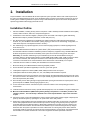
2. Installation ..........................................................................................................................................2-1
Installation Outline............................................................................................................................................... 2-1
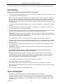
Site Planning ....................................................................................................................................................... 2-2
Tools and Supplies.............................................................................................................................................. 2-2
Preparing the Main Distribution Frame................................................................................................................ 2-3
KSU Wiring.......................................................................................................................................................... 2-5
MDF (Main Distribution Frame) .................................................................................................................... 2-5
No MDF........................................................................................................................................................ 2-5
Typical MDF Installation ...................................................................................................................................... 2-6
KSU Components................................................................................................................................................ 2-7
Replacing a 408 M / E ......................................................................................................................................... 2-7
KSU Assembly – Add-on Modules ...................................................................................................................... 2-8
Adding a DPM8 (Digital Port Module – 8 port) .................................................................................................... 2-9
Adding an APM4 (Analog Port Module – 4 port) ............................................................................................... 2-10
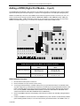
Adding a COM4 (CO Line Module – 4 port) ...................................................................................................... 2-11
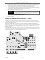
Adding an MDM (Modem Module)..................................................................................................................... 2-13
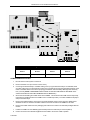
Adding an AAM (Automated Attendant Module)................................................................................................ 2-14
Adding a KSU2 (Key Service Unit-2, second cabinet)....................................................................................... 2-14
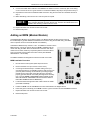
Adding a Music Source(s) ................................................................................................................................. 2-15
Adding an External Pager (paging system) ....................................................................................................... 2-16
Adding Loud Bell Control or Gate Control ......................................................................................................... 2-16
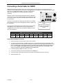
Connecting a Serial Cable for PC-DBA ............................................................................................................. 2-17
Connecting a Serial Cable for SMDR ................................................................................................................ 2-18
P7290 IMM
TOC-1
DX-80 INSTALLATION AND MAINTENANCE MANUAL
Power-up Initialization ....................................................................................................................................... 2-19
3. Features ..............................................................................................................................................3-1
Account Code – Voluntary / Forced / Verified
79........................................................................................ 3-1
Alarm Clock – Extension !92 .................................................................................................................. 3-3
Alarm Clock – System (System Reminder) ......................................................................................................... 3-5
Alphanumeric Display (Super Twist) ................................................................................................................... 3-7
Answering Machine Emulation/Record & Pickup (via DX-80 Hard Drive {in-skin} Voice Mail) ............................ 3-7
Attendant Administration (Admin.)
!-0 .................................................................................................. 3-9
Attendant - .................................................................................................................................................... 3-12
Attendant / Extension DSS Console.................................................................................................................. 3-15
Attendant / Extension DSS Console Button Programming !,4 ............................................................ 3-17
Automated Attendant (optional)......................................................................................................................... 3-19
Automatic CO Line Ringing Modes ................................................................................................................... 3-24
!94 ............................................................................................................................... 3-26
Automatic Record (via DX-80 Hard Drive Voice Mail) !67 ................................................................. 3-27
Automatic Redial !78 ............................................................................................................................ 3-29
Automatic Selection (CO/Intercom) !95 ............................................................................................... 3-31
Automatic Hold
Auxiliary Lamp / LED Status Bar ....................................................................................................................... 3-32
Background Music (BGM) 771/772 ............................................................................................. 3-33
Barge-In (Intrusion) ........................................................................................................................................... 3-34
Battery Back-Up (Memory) ................................................................................................................................ 3-34
Battery Back-Up (System)................................................................................................................................. 3-34
Busy Lamp Field – DSS .................................................................................................................................... 3-34
!,2 ................................................................................................................ 3-35
Call Operator / Attendant 0 ............................................................................................................................ 3-36
Busy Ring – Allow/Deny
Call Back – CO Line [cbck] ............................................................................................................................... 3-39
Call Back – Extension [cbck] ............................................................................................................................. 3-40
Call Duration Timer ........................................................................................................................................... 3-42
Call Forward – Extension !2 ..................................................................................................................... 3-42
Call Forward – CO Line Predefined (No Answer condition) .............................................................................. 3-48
Call Forward – Extension Predefined ................................................................................................................ 3-50
Call Park / Call Park Answer
!73 .......................................................................................................... 3-53
Call Pick Up – Group * ................................................................................................................................. 3-54
Caller ID to Analog Ports (Standard) ................................................................................................................. 3-55
Caller ID (Standard on all CO Lines) ................................................................................................................. 3-56
Caller Identification Table – Callback !6, ............................................................................................ 3-56
Camp On – Extension [camp].............................................................................................................................. 3-59
Class of Service – Extension............................................................................................................................. 3-60
CO Line Alternate Route ................................................................................................................................... 3-62
CO Line Assignment ......................................................................................................................................... 3-64
CO Line Calling & I-Use Indication .................................................................................................................... 3-66
CO Line Group .................................................................................................................................................. 3-67
CO Line Group Directory Number Swapping .................................................................................................... 3-69
CO Line Loop Supervision (Talk/Hold Abandon)............................................................................................... 3-70
CO Line Name / Label Programming ................................................................................................................ 3-73
CO Line Programming Copy ............................................................................................................................. 3-74
CO Line Queuing / Callback [cbck] ................................................................................................................... 3-77
CO Line Receive Assignment ........................................................................................................................... 3-77
CO Line Ring Assignment (Answer Position) .................................................................................................... 3-79
CO Line Ring Type Assignment ........................................................................................................................ 3-81
CO Line Ringing Modes !63 ................................................................................................................. 3-82
CO Line Signaling / Dialing Type (Tone/Pulse) ................................................................................................. 3-85
P7290 IMM
TOC-2
DX-80 INSTALLATION AND MAINTENANCE MANUAL
CO Line Type Assignment ................................................................................................................................ 3-86
Conference, Meet Me 390 ~ 397 .................................................................................................. 3-88
Conference, Supervised/Unsupervised !77 .......................................................................................... 3-90
Database Administration – Via PC-DBA............................................................................................................ 3-94
Database Administration – Via Any Digital Extension
!+* .................................................................. 3-103
!69 .................................................................................................................................. 3-104
Dial Pad Confirmation / Touch Tone !;1 ............................................................................................ 3-105
Default Set
Direct Inward System Access (DISA) (Optional AAM required) ...................................................................... 3-105
Direct Station Selection Console ..................................................................................................................... 3-108
Discriminating Ringing..................................................................................................................................... 3-110
Distinctive Ringing – CO Line.......................................................................................................................... 3-112
Distinctive Ringing – Extension
)7 .......................................................................................................... 3-113
!4 ................................................................................................................................... 3-114
Do Not Disturb – One Time !4 ............................................................................................................... 3-115
Do Not Disturb
Do Not Disturb – Override ............................................................................................................................... 3-115
End-To-End Signaling/Voice Mail Dialing Ratio .............................................................................................. 3-116
Enhanced Lettering Scheme ........................................................................................................................... 3-117
Extension Feature Status Check !.8 .................................................................................................. 3-119
Extension Paging Groups................................................................................................................................ 3-119
Extension Password........................................................................................................................................ 3-121
Extension Pick Up Groups .............................................................................................................................. 3-123
Extension Programming Copy......................................................................................................................... 3-124
Extension Swapping........................................................................................................................................ 3-126
Extension User Name ..................................................................................................................................... 3-127
External Music Source (Two Standard)
771/772 ........................................................................ 3-129
External Paging 777 ............................................................................................................................. 3-131
FAX Detection with Automatic Transfer........................................................................................................... 3-133
Feature Button Disable ! ............................................................................................................................ 3-134
!58 ....................................................................................................................... 3-136
Feature / Directory Number Lookup !/5 ............................................................................................. 3-136
Feature Key Reset
Flash – Analog Port (SLT) Flash Recognition ................................................................................................. 3-139
!3 ................................................................................................................................. 3-141
Flash – PBX Line !3 ............................................................................................................................... 3-142
Flexible Feature Button Inquiry !/3 .................................................................................................... 3-144
Flexible Feature Button Programming !/3 .......................................................................................... 3-144
Flash – CO Line
Flexible Numbering Plan ................................................................................................................................. 3-147
!4 ........................................................................................................... 3-151
Forced Intercom Tone Ring * ...................................................................................................................... 3-151
Forced Intercom Call Forward
Headset Jack................................................................................................................................................... 3-152
Headset Mode
Hidden Codes
!9/ .............................................................................................................................. 3-152
!61 ............................................................................................................................... 3-153
Hold – Common (System) & I-Hold Indication
................................................................................. 3-154
........................................................................................................................ 3-156
Hold – Exclusive
Hold Abandon.................................................................................................................................................. 3-158
Hold Reminder ................................................................................................................................................ 3-160
Holding Call Answer – Select
............................................................................................................ 3-161
!/6.............................................................................................................. 3-161
Hotel Mode – Alarm Clock Extension !92 .......................................................................................... 3-162
– Room Status !7/ .............................................................................................................................. 3-162
Hot Key Enable / Disable
P7290 IMM
TOC-3
DX-80 INSTALLATION AND MAINTENANCE MANUAL
Hotline !9* .......................................................................................................................................... 3-164
Hour Mode Selection (12/24) .......................................................................................................................... 3-166
Intercom Calling - Non Blocking ...................................................................................................................... 3-167
!65 .......................................................................................................................... 3-167
Intercom Mode Selection !98 .............................................................................................................. 3-168
- Intercom Button
Intrusion - Extension/CO Line ......................................................................................................................... 3-169
Last Number Redial
!8............................................................................................................................ 3-171
.................................................................. 3-172
LCD & Interactive Buttons
Loud Bell / External Page / Music Source – Control........................................................................................ 3-173
!59, /....................................................................................................................... 3-174
Memo Pad !5* .................................................................................................................................. 3-175
Messaging – Call Me, Text or Voice !96 ............................................................................................ 3-176
Messaging – Status Text !90 .............................................................................................................. 3-180
Meet Me Page
Modem (Optional MDM) .................................................................................................................................. 3-182
Monitor – Extension/CO Line .......................................................................................................................... 3-184
Music On Hold (Two Source) .......................................................................................................................... 3-186
Mute
.................................................................................................................................................. 3-187
Night Service Mode / Activate !63 ...................................................................................................... 3-187
Off Hook Voice Announce with Hands-free Answerback................................................................................. 3-189
On Hook Dialing .............................................................................................................................................. 3-190
Page Allow / Deny !#9 ........................................................................................................................ 3-190
Paging .......................................................................................................................................................... 3-190
Pause / Pause Insertion !70 ............................................................................................................... 3-193
PBX Compatibility............................................................................................................................................ 3-195
Phantom Lines / Virtual Numbers
700~729................................................................................ 3-197
Phone Lock / Unlock !97..................................................................................................................... 3-198
Privacy .......................................................................................................................................................... 3-199
Privacy Release .............................................................................................................................................. 3-199
Private Line ..................................................................................................................................................... 3-201
Pulse to DTMF Conversion * ...................................................................................................................... 3-203
Recall .......................................................................................................................................................... 3-203
Recorded Announcement Device.................................................................................................................... 3-204
Release Key !52 ................................................................................................................................ 3-206
Reminder Tones.............................................................................................................................................. 3-207
Remote Programming via PC-DBA ................................................................................................................. 3-207
Ringing Level / Muted Ringing ........................................................................................................................ 3-210
Ringing Line Priority ........................................................................................................................................ 3-211
Saved Number Redial !51 .................................................................................................................. 3-211
Single Line Telephone – Flash ........................................................................................................................ 3-212
Single Line Telephone – CO Line Flash /3 ............................................................................................. 3-214
Single Line Telephone / Analog Device Support ............................................................................................. 3-214
Speakerphone ................................................................................................................................................. 3-215
Speed Dial – Extension/System ...................................................................................................................... 3-215
Station Message Detail Recording (SMDR) .................................................................................................... 3-220
System Time and Date.................................................................................................................................... 3-223
Tenant Groups ................................................................................................................................................ 3-225
Toll Restriction – Class of Service................................................................................................................... 3-228
Tone / Pulse / Inter-digit Duration Selection .................................................................................................... 3-232
Touch Tone On/Off
Transfer
P7290 IMM
!/1....................................................................................................................... 3-234
............................................................................................................................................... 3-234
TOC-4
DX-80 INSTALLATION AND MAINTENANCE MANUAL
Transfer and Answer Call !68 ............................................................................................................. 3-236
UCD / Hunt Groups (1~24) 410~433 (Linear/Distributed/All Ring) ................................................................ 3-237
UCD Agent Log Off/Log On !91 ........................................................................................................ 3-243
UCD Overflow and Reroute............................................................................................................................. 3-243
UCD Voice Announce Group .......................................................................................................................... 3-245
!98 ............................................................................................ 3-248
Voice Call Recorder (via Voice Mail System) !67 .............................................................................. 3-248
Voice Mail – Analog Integration !64 .................................................................................................. 3-250
Voice Mail – Digital Integration (optional) !64 ..................................................................................... 3-257
Voice Announce – Hands-free Reply
Volume Control................................................................................................................................................ 3-261
Warning Tone / CO Line Call Limiter............................................................................................................... 3-262
4. Maintenance and Trouble Shooting.................................................................................................4-1
User Maintenance ............................................................................................................................................... 4-1
Technical Problem Solving.................................................................................................................................. 4-1
Maintenance Utilities ........................................................................................................................................... 4-7
P7290 IMM
TOC-5
DX-80 INSTALLATION AND MAINTENANCE MANUAL
P7290 IMM
TOC-6
DX-80 INSTALLATION AND MAINTENANCE MANUAL
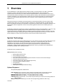
1. Overview
The Comdial DX-80 is a fully digital hybrid key telephone system. The DX-80 utilizes “Loop Start” central office
(Telephone Company) line interfaces and a mix of analog and digital extension ports to provide office
communications and connectivity to the Public Switched Telephone Network. The DX-80 delivers a vast array of
office productivity features and telephone use enhancing features including Caller Identification (required Telephone
Company subscription) in the standard package. Unlike most systems that support Caller ID, the DX-80 supports
Caller ID to DX-80 proprietary digital extensions and to third-party, Caller ID capable analog devices (cordless
telephones, etc.)
Although most features are standard, the DX-80 provides for several optional features to further enhance office
communications. Built-in voice processing integration packages are: Automated Attendant, Cost Effective FlashBased Voice Mail/Auto Attendant and Cost Effective, fully-featured Hard Drive-based Voice Mail/Auto Attendant. The
DX-80 platform allows the application of these voice processing platforms without loss of valuable system port
resources.
The DX-80 is comprised of an application configured, expandable Key Service Unit (KSU) platform. There is one fully
featured Digital Executive (display) Telephone that delivers access to all system functionality. The system
architecture provides an expandable interface for digital port growth and analog port growth. The basic configuration
supports both device types. (Analog ports might be used for plain old telephones, fax machines, modems, etc.) The
DX-80 is designed to meet the telecommunications needs of small to medium business offices.
System Technology
The DX-80 incorporates state of the art digital technology for voice switching and call processing utilizing Pulse Code
Modulation and Time Division Multiplexing (PCM/TDM). The DX-80 is a non-blocking switch, with no loss or
degradation of voice signals. The system is stored-program control and utilizes a 16-bit, 20 MHz main
microprocessor and peripheral devices (extensions and CO lines) processors in a distributed processing
configuration. Memory consists of 640K bytes of ROM (Read Only memory) and 384K bytes of RAM (Random
Access Memory) (RAM is lithium battery protected).
The DX-80 is factory equipped as follows:
KSU1 (PN 7201) with the following
•
•
•
•
•
•
•
•
•
•
Eight (8) digital extension ports
Four (4) analog device ports
Four (4) CID ready CO Line ports
Two music source inputs (can be assigned as desired to CO lines for hold music/messages
One power failure port (CO Line 1)
One control contact (LBC, Gate, External Page Control)
One external paging equipment interface
Two serial ports
PC-DBA programming
SMDR (Station Message Detailed Recording).
Optional Equipment
The optional equipment is listed below:
KSU2 (PN 7202) used to expand the system capacity beyond KSU1 limits. Includes eight (8) digital
extension ports, four (4) CO line ports and one power failure port (CO line circuit 1).
DPM8 (PN 7220) (Digital Port Module - 8 circuit) (installs into KSU1 or KSU2)
APM4 (PN 7230) (Analog Port Module - 4 circuit) (installs into KSU1 or KSU2)
COM4 (PN 7210) (CO line Module - 4 circuit with one power failure port on first CO line circuit) (installs into
KSU1 or KSU2)
MDM (PN 7249) (Modem Module) (for use with off-site programming) (installs into KSU1 only)
P7290 IMM
1-1
DX-80 INSTALLATION AND MAINTENANCE MANUAL
AAM (PN 7240) (Automated Attendant Module - 4 port, one menu for routing, 10 announcements for various
caller greetings) (installs into KSU1 only)
FL-4 (PN 7241) (Flash-based, 4-port Voice Mail with Auto Attendant, 1.5 hours storage and 100 mailboxes)
FL3HR (PN 7241E) (Flash-based Voice Mail storage expansion module adds 3 hours storage to the FL-4)
PC-8 (PN 7243) (Hard Drive-based, 8-port Voice Mail with Auto Attendant, 130 hours storage and 100
mailboxes)
The maximum system configuration is 16 CO lines, 56 extensions (48 digital and 8 analog) and 8 voice
processing channels.
Configuration
The Comdial DX-80TM platform is comprised of one full-featured key telephone model and two modular KSUs (Key
Service Unit). Several modules are available for enhanced system applications and configuration expandability.
KSU1 Components
n
n
n
CPM (Central Processor Module) with:
Two Serial Ports
Two Music Ports
One Control Contact (External Paging/LBC/Gate Control)
One External Page Equipment Interface Connection
Socket connectors for:
nd
...KSU2(labeled “2 Cabinet”), MDM, and VP modules (AAM, FL-4, and PC-8)
The CPM is installed inside of KSU1 to the 408M ribbon cable J4 (also labeled “To CPM”)
Standard 408M (part of 7201) with:
4 CO Line Ports
1 Power Failure Transfer Port for the first CO line circuit
8 Digital Ports
Ribbon cable (J1, also labeled “COM4”) for connection to the COM4 Module (PN 7210) in
KSU1
Ribbon cable sockets (J2 and J3, also labeled “To DPM8/APM4”) for connection of DPM8
(PN 7220) or APM4 (PN 7230) modules.
Standard APM4 (part of 7201) with:
4 Analog Device Ports (installed on ribbon cable J5, also labeled “APM4”)
KSU2 Components
n
Standard 408E (part of 7202) with:
4 CO Line Ports
1 Power Failure Transfer Port for the first CO line circuit
8 Digital Ports
Ribbon cable (J1, also labeled “COM4”) for connection to the COM4 Module (PN 7210)
Ribbon cable sockets (J2 and J3, also labeled “To DPM8/APM4”) for connection of DPM8
(PN 7220) or APM4 (PN 7230) modules.
nd
Shielded cable (J4) for connection to CPM socket JP2 (also labeled “2 Cabinet”) in KSU1
Voice Processing Modules
The DX-80 provides for several voice processing options. (Voice processors are commonly referred to as
Voice Mail systems. However this term is too generic to accurately describe the options available and how
they might be applied.) The optional Voice Processors that can be added to the DX-80 are fixed system
resources that do not require peripheral device ports (analog or digital). This significant advantage means
that the DX-80 VP options can be added to any DX-80 configuration without “port loss”. (Most
P7290 IMM
1-2
DX-80 INSTALLATION AND MAINTENANCE MANUAL
communications products interface voice processors of some sort but suffer the ill effects of reducing the
overall capacity of the system when the voice processor is connected.) Because the DX-80 doesn’t use
conventional peripheral ports to interface the VPs, we refer to the VP connectivity in terms of “channels.”
AAM (Automated Attendant Module): The AAM provides four channels for automated attendant operation
only. The AAM is then capable of handling four calls simultaneously. Callers answered by the AAM are
greeted by one of four (4) greetings associated to the DX-80 mode of operation (Day / Evening / Alternate /
Temporary). Various other announcements are also included for caller processing (see Automated
Attendant in the Features section of this manual for more details).
FL-4 (Flash-based, four port VM with Automated Attendant): The FL-4 provides four channels for
automated attendant and voice mail operation. The FL-4 is equipped to support up to 100 voice mailboxes
and 1.5 hours of message storage (including the various greeting announcements).
FL3HR (Flash-based, three-hour message storage expansion): The FL3HR is added to the FL-4 above
to increase the total message storage time from 1.5 hours to 4.5 hours.
PC-8 (PC-based, eight port VM with Automated Attendant): The PC-8 provides eight channels for
automated attendant and voice mail operation. The PC-8 is equipped to support up to 100 voice mailboxes
and 130 hours of message storage (including the various greeting announcements).
All of the above Voice Processors are connected to the DX-80 Central Processor Module (CPM) via specific
interface socket(s). (See install details for the various devices, AAM included in this manual, FL-4 and PC-8
included with the unit.)
P7290 IMM
1-3
DX-80 INSTALLATION AND MAINTENANCE MANUAL
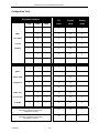
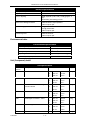
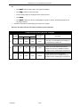
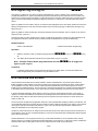
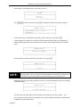
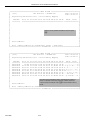
Configuration Table
Equipment Installed
COM4
DPM8
APM4
CO
Digital
Analog
Lines
Ports
Ports
4
8
4
KSU1
1
4
16
4
(one APM4
2
4
24
4
8
8
4
included
1
standard)
1
1
8
16
4
1
2
8
24
4
1
1
8
16
8
4
8
1
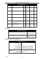
KSU2
1
4
16
adds to KSU1
2
4
24
8
8
configuration
1
1
1
8
16
(KSU2 does
1
2
8
24
not come with
1
2
1
8
24
4
an APM4)
1
1
2
8
16
8
16
48
8
Maximum configuration using 100%
of digital port capacity
16
Maximum configuration using 100%
of analog port capacity
P7290 IMM
1-4
32
16
DX-80 INSTALLATION AND MAINTENANCE MANUAL
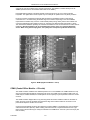
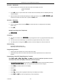
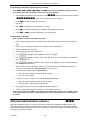
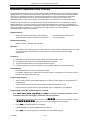
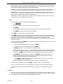
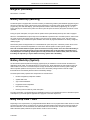
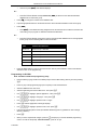
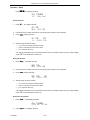
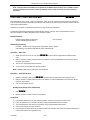
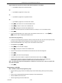
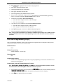
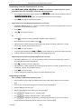
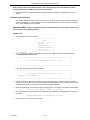
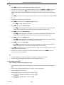
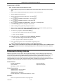
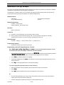
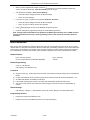
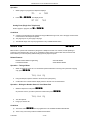
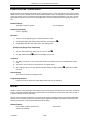
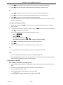
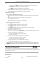
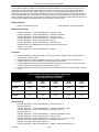
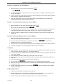
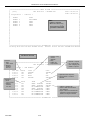
Key Service Unit
The DX-80 Key Service Unit (KSU) is a modular flat-pack design. Two KSU’s (KSU1 and KSU2) may be
equipped to achieve the total system capacity of 16 CO lines, 56 Extensions (48 digital and 8 analog) and 8
Voice Processing Channels. KSU1 is factory equipped with one 408M, one APM4 and the CPM (Central
Processor Module). KSU2 is factory equipped with one 408E. Each KSU is a self-contained cabinet with
internal power supply. The power supply AC transformer can be hard-wire selected for either 117vac or
230vac operation. (It is shipped wired for 117vac operation.) The KSU is designed to be mounted on the
wall and is shipped with a wall mounting template. The compact KSU weighs less than 20 pounds and is UL
Listed.
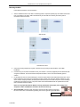
Panels installed over various KSU openings may be removed or repositioned to accommodate exterior
connection requirements. Three such panels are present. One may be removed to route a serial cable
through the KSU outer housing for connection of ancillary SMDR equipment. Another may be removed to
route a serial (NULL Modem) cable through the KSU outer housing for direct connection of a PC for on-site
PC-DBA programming. One KSU opening panel may be removed or repositioned to accommodate cable
entry requirements through the outer housing for connection of station/extension cables or to the MDF.
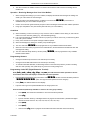
From the exterior, with covers in place, KSU1 and KSU2 look identical. However, KSU1 contains the Central
Processor Module (CPM) (system call processing).
COMDIAL
Figure 1: DX-80 Key Service Unit
Power Supply
The power supply circuitry of the DX-80 incorporates a linear design AC transformer with a choice of input
voltage taps. The transformer primary windings are shipped wired for 117vac applications. A factory
insulated tap wire may alternately be connected for 230vac applications. Since the power supply is linear in
design the output voltage varies between 21.6vdc and 32vdc depending on load and stability of the input
voltage. The output voltage is delivered to the 408M (in KSU1, 408E in KSU2) for voltage regulation. All
system operation and logic voltages are produced at the 408M/E.
Two fuses are equipped on the power supply board, one for ac input over-voltage protection and one for DC
output over-current protection. A main power switch is accessible when the KSU cover is in place. In the
event battery backup operation is desired the KSU power cord can be connected to a external (ancillary)
UPS (Un-interruptible Power Supply). It is the responsibility of the installer to match the battery
requirements/UPS requirement to the specific needs of the equipment owner.
To determine the battery requirement needs and UPS requirement use the chart in Specifications (this
section) to find the current draw and necessary Amp/Hour back up support that the battery/UPS is to supply.
P7290 IMM
1-5
DX-80 INSTALLATION AND MAINTENANCE MANUAL
CPM (Central Processor Module)
The CPM module is equipped standard in KSU1. This board contains all circuitry required to control the fully
equipped DX-80. All digital voice switching and call processing data switching is accomplished via the CPM.
The CPM has one ribbon cable connector for connection to the KSU1 408M and five (5) connector sockets
nd
for connection of the system built-in modem, voice processor and 2 Cabinet (KSU2). Since the CPM
comes installed inside of KSU1 the CPM ribbon cable is already in place and connected to the KSU1-408M
J5 socket. Assuming the orientation of the KSU1 cabinet is installed on the wall; the two horizontal
connector sockets in the upper right corner of the CPM are for the MDM (Modem Module). The connector
socket labeled “2nd Cabinet” is for connection to the KSU2-408E if that expansion is required. The
remaining two connector sockets on the CPM, one at the left side, the other at the right side are for the voice
processor solution. (The voice processor solution can be any of three possible choices; AAM, FL-4 or PC-8.)
The CPM also provides the following standard connectors:
•
•
•
•
•
•
Music Channel 1 - On Hold/Background Music Interface
Music Channel 2 - On Hold/Background Music Interface
Control Contact (Loud Bell / Door / External Page Control)
External Paging Equipment Interface
RMP Serial Port - for on-site PC-DBA system database programming
SMDR Serial Port - for connection to ancillary SMDR/Call Accounting equipment
The CPM has two Option Strap jumpers one for database start-up (J11) and one for Music Channel One
source (internal/external) selection (JP30).
J11 Cold Start/Normal: J11 is used to force load database default factory settings. This jumper will
normally never require operation after the initial power up sequence is completed. However should the need
arise to return the site database to the factory settings this jumper is used to accomplish the task.
JP30 Internal/External: JP30 is used to select the Music Channel 1 source. The DX-80 provides a
synthesized music source for music on hold in applications where no music source is available. The
synthesized tune is repeated. JP30 is in the “External” position when it ships from the factory.
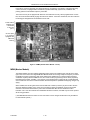
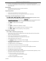
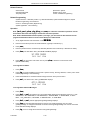
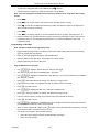
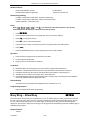
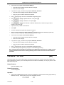
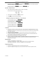
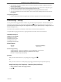
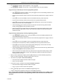
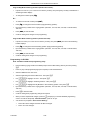
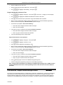
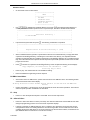
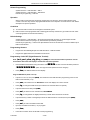
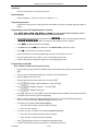
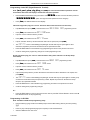
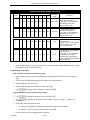
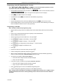
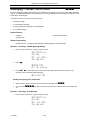
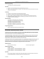
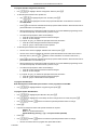
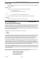
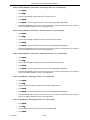
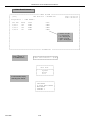
408M (KSU1 component)
The 408M is the large circuit board that is packaged inside of KSU1. The 408M provides interface for up to 4
loop-start CO Lines and 8 Digital Extension Ports. Additionally the 408M regulates the 24 volt DC power
from the source to produce all required logic voltages and operations voltages. There is also a Power Failure
Port located on the 408M that is connected to the first CO Line circuit. Whenever power fails this port
becomes active with dial tone from the CO line connected to the first CO line port.
The 408M is equipped with a Heart-beat LED that indicates processing activity on the PCB. (The 408M
peripheral processor is operating when the Heartbeat LED is flashing.) The KSU1 operation LED (located
next to the power switch) is tied to the 408M Heartbeat LED. Therefore, when the LED next to the power
switch is flashing, the 408M is active.
The KSU1-408M has three ribbon cables; one at the upper right and oriented in a horizontal position (J1) is
used to interface a COM4 if required to expand the system CO Line capacity. The other two ribbon cables
located at the upper center and oriented in a vertical position. J4 is used to interface the DX-80 CPM. J5
connects to the standard APM4 installed in KSU1.
Each CO line circuit incorporates over-voltage protection, ring detector, loop detector, loop/pulse-dial relay,
current sink circuit, coupling/isolation transformer (impedance 600:600), hybrid circuit, CODEC & filter,
polarity guard circuit and Radio Frequency noise filter.
P7290 IMM
1-6
DX-80 INSTALLATION AND MAINTENANCE MANUAL
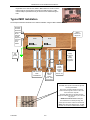
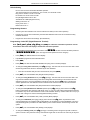
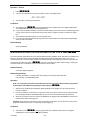
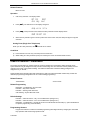
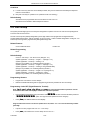
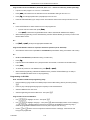
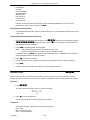
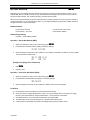
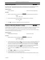
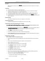
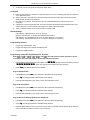
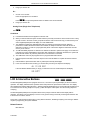
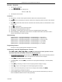
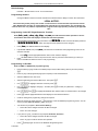
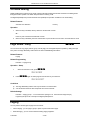
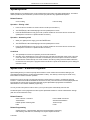
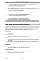
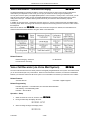
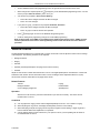
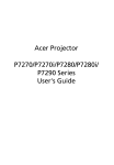
COM4
ribbon cable
APM4 ribbon
cable
CPM ribbon
cable
Four Loop Start
CO Line ports
Eight digital
ports
Power Failure
port
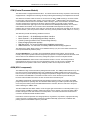
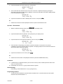
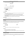
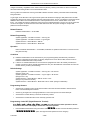
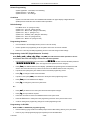
Figure 2: KSU1 shown with cover, CPM and APM4 removed. (408M exposed)
The fourth CO Line port is equipped with CNG Fax Tone Detection circuitry. When programmed as a “FAX”
line, this circuit will automatically engage the FAX Tone detector. If FAX tone is detected, the call is routed to
the analog port designated as the destination for fax calls.
Each digital port (connects to Digital Executive Telephones and DSS Consoles) is comprised of a
proprietary octal ASIC (Application Specific Integrated Circuit) transceiver. There are three data channels in
operation at each digital port via the octal transceiver. One channel is used for call processing control of
digital terminal functions/operations and two channels are used for the digital voice channel requirements.
Each digital station interface is protected against circuit wiring shorts by an over-current protection
Polyswitch. The digital station circuit requires only one cable pair to operate and is not polarity sensitive.
Physical connection of digital extensions, power failure telephones and CO lines to the 408M module is
made through convenient RJ-11 connectors along the bottom edge of the module.
408E
The 408E is very similar to the 408M, however it is unique to KSU2. The 408E (KSU2 component) provides
interface for up to 4 loop-start CO Lines and 8 Digital Extension Ports. Additionally the 408E regulates the
24 volt DC power from the source to produce all required logic voltages and operations voltages. There is
also a Power Failure Port located on the 408E that is associated to the first CO Line circuit. Whenever
power fails this port becomes active with dial tone from the CO line connected to the first CO line port.
The 408E is equipped with a Heartbeat LED that indicates processing activity on the PCB. (The 408E
peripheral processor is operating when the Heartbeat LED is flashing.) The KSU2 operation LED (located
next to the power switch) is tied to the 408E Heartbeat LED. Therefore, when the LED next to the power
switch is flashing, the 408E is active.
The KSU2-408E connections are almost identical to those on the 408M (KSU1). The exception is the long
shielded cable used to connect KSU2 to the CPM inside of KSU1. (Also notice: that there is no standard
APM4 installed inside of KSU2.)
Each CO line circuit incorporates over-voltage protection, ring detector, loop detector, loop/pulse-dial relay,
current sink circuit, coupling/isolation transformer (impedance 600:600), hybrid circuit, CODEC & filter,
polarity guard circuit and Radio Frequency noise filter.
The fourth CO Line port is equipped with CNG Fax Tone Detection circuitry. When programmed as a “FAX”
line, this circuit will automatically engage the FAX Tone detector. If FAX tone is detected, the call is routed to
the analog port designated as the destination for fax calls.
P7290 IMM
1-7
DX-80 INSTALLATION AND MAINTENANCE MANUAL
Each digital port (connects to Digital Executive Telephones and DSS Consoles) is comprised of a
proprietary octal ASIC (Application Specific Integrated Circuit) transceiver. There are three data channels in
operation at each extension port via the octal transceiver. One channel is used for call processing control of
digital terminal functions/operations and two channels are used for the digital voice channel requirements.
Each digital station interface is protected against circuit wiring shorts by an over-current protection
Polyswitch. The digital station circuit requires only one cable pair to operate and is not polarity sensitive.
Physical connection of digital extension terminals, power failure telephones and CO lines to the 408M
module is made through convenient RJ-11 connectors along the bottom edge of the module.
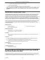
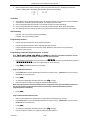
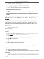
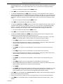
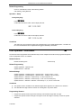
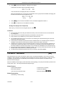
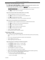
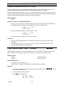
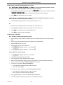
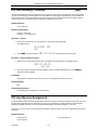
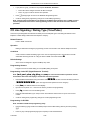
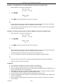
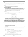
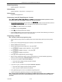
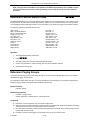
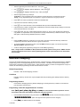
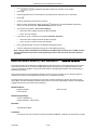
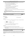
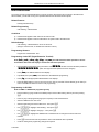
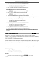
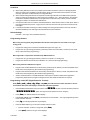
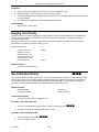
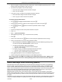
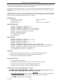
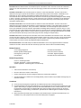
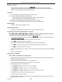
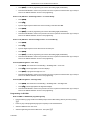
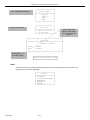
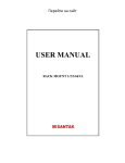
APM4 (Analog Port Module - 4 Circuits)
The APM4 provides four separate analog device ports. This allows the DX-80 to support auxiliary office
equipment found on the business premises such as fax machines, PC/Mac modems and analog telephones
(single line telephones). The APM4 generates -30VDC and 20-25Hz, 50V square wave ringing for operation.
The APM4 is equipped with a Heartbeat LED that indicates processing activity on the PCB. (The APM4
peripheral processor is operating when the Heartbeat LED is flashing.)
The APM4 provides DTMF receivers for each analog port. Ancillary analog devices connected to APM4
analog ports must generate DTMF signaling. (Pulse dial (rotary-dial) telephones/equipment are not
supported.) All connections are via RJ-11 connectors along the bottom edge of the module. KSU1 is
delivered with one APM4 installed on Ribbon Connector J5 as standard equipment.
APM4’s may be installed on 408M/E-J5 (standard in KSU1:408M-J5), 408M/E-J2 or 408M/E-J3. (Note it is
not possible to install an APM4 on both J2 and J3 on any one 408.)
When an APM4 is installed via J2 or J3, they take the place of DPM8 modules that might be installed in
those locations. Therefore APM4 modules installed using J2 or J3 will reduce the total number of Digital Port
Modules (DPM8) possible.
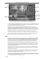
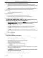
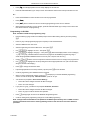
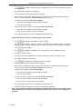
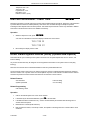
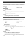
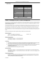
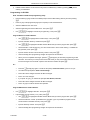
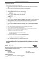
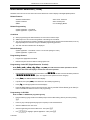
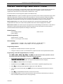
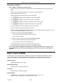
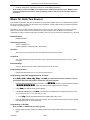
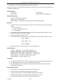
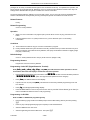
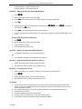
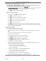
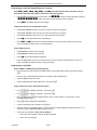
Figure 3: APM4 (Analog Port Module - 4 Circuits)
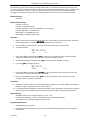
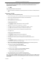
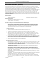
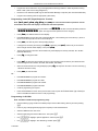
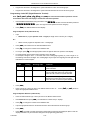
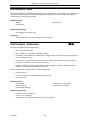
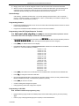
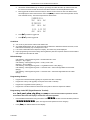
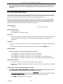
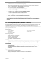
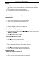
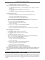
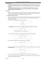
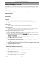
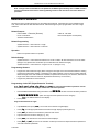
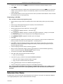
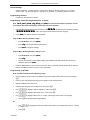
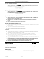
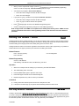
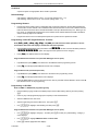
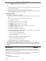
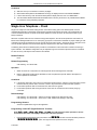
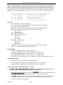
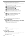
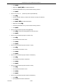
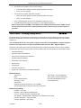
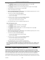
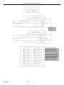
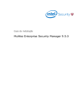
DPM8 (Digital Port Module - 8 Circuits)
The DPM8 module expands the DX-80 system capacity of digital ports DET (Digital Executive Telephones)
and DSS Consoles. Each digital port is comprised of a proprietary octal ASIC (Application Specific
Integrated Circuit) transceiver. There are three data channels in operation at each digital port via the octal
transceiver. One channel is used for call processing control of digital terminal functions/operations and two
P7290 IMM
1-8
DX-80 INSTALLATION AND MAINTENANCE MANUAL
channels are used for the digital voice channel requirements. The DPM8 is controlled directly from the
408M/E (therefore there is no heartbeat LED located on the DPM8.)
Each digital station interface is protected against circuit wiring shorts by an over-current protection
Polyswitch. The digital station circuit requires only one cable pair to operate and is not polarity sensitive.
Physical connection of digital port terminals (DET and DSS) to the DPM8 module is made through
convenient RJ-11 connectors along the bottom edge of the module. Depending on the site installation
requirements the installer may choose to route terminal (station) wiring directly into the KSU cabinet and
connect the individual terminal cables to the RJ-11 extension port desired via field crimped RJ-11 plugs.
This streamlined installation capability can eliminate the traditional cross-connect field hence reduce costs of
installation. (Be advised that we do not recommend this practice since it is inherently difficult to
service. When using field-crimping tools, use quality tools. Cheap tools yield bad connections.)
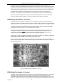
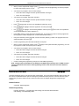
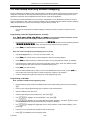
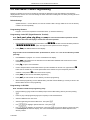
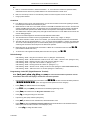
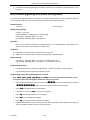
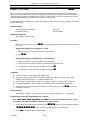
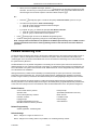
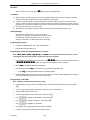
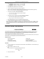
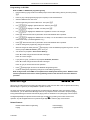
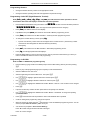
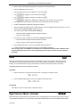
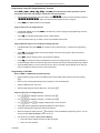
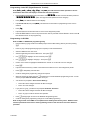
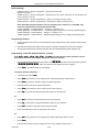
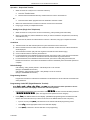
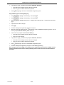
Figure 4: DPM8 (Digital Port Module - 8 Port)
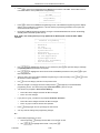
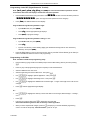
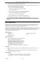
COM4 (Central Office Module - 4 Circuits)
The COM4 module is installed in the dedicated position via J1 of the 408M/E. The COM4 interfaces 4 loopstart CO (Central Office [Telephone Company]) lines. Since one COM4 may be installed in KSU1 and one
COM4 may be installed in KSU2, the DX-80 system CO line capacity may be expanded to interface 16 total
CO lines.
The COM4 module is shipped with four (4) mounting stand-offs used to install the board into the KSU1 or
KSU2. Five RJ11 jacks are provided along the bottom edge of the COM4 module for connection of one
power failure telephone and the four CO lines.
CO lines are terminated at the site by the Telephone Company (RBOC or equivalent) at a point of interface
called the Demarcation (Demarc). When ordering CO lines for the site, request termination on RJ11 type
jacks. Doing so allows CO line(s) to easily be extended to the COM4 RJ11 connector. (One CO line per jack
and connector.)
P7290 IMM
1-9
DX-80 INSTALLATION AND MAINTENANCE MANUAL
Each CO line circuit incorporates over-voltage protection, ring detector, loop detector, loop/pulse-dial relay,
current sink circuit, coupling/isolation transformer (impedance 600:600), hybrid circuit, CODEC & filter,
polarity guard circuit and Radio Frequency noise filter.
The fourth CO Line port is equipped with CNG Fax Tone Detection circuitry. When programmed as a “FAX”
line, this circuit will automatically engage the FAX Tone detector. If FAX tone is detected, the call is routed to
the analog port designated as the destination for fax calls.
Power Failure
Transfer port
– associated
to CO Line
port 1
CO Line ports
1~4. (Circuit 4
equipped with
CNG FAX
Detect)
Figure 5: COM4 (Central Office Module - 4 Port)
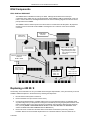
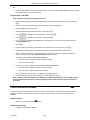
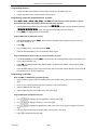
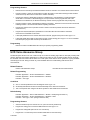
MDM (Modem Module)
The Modem Module is a self-contained integrated modem unit that is installed at JP5 and JP6 in the upper
right corner of the CPM. The integrated Modem Module allows the servicing Telephone Company to access
the telephone system programming and remote maintenance utilities from an off-site location (password
verification required). When the MDM is used, the remote location programming is done via the proprietary
DOS-based PC program “PC-DBA.” This program can be obtained free of charge at the Comdial Web site
www.comdial.com or from the Comdial Customer Services Department. (Diskette and shipping charges may
apply.)
When installed, the servicing technician uses PC-DBA and a modem (in the PC) to place a call to the site
where the DX-80 is installed. If one of the voice processing systems are installed, routing to the modem
extension is automated. Otherwise the person who answered this data call must transfer the call to
Extension 199*. Once the modems have established the data connection, PC-DBA may be used to perform
all servicing operations.
(*The MDM default extension number is 199. This number can be changed and therefore may be different
for some DX-80 systems.)
P7290 IMM
1-10
DX-80 INSTALLATION AND MAINTENANCE MANUAL
Figure 6: MDM (Modem Module)
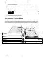
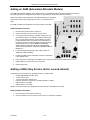
AAM (Automated Attendant Module)
The Automated Attendant Module is a self contained integrated module that adds automatic answering of
selected CO lines and a single-level menu for greeting callers and routing them to DX-80 system
destinations. The AAM is a wonderful low cost voice processing system that can handle all call traffic or act
as a backup to the primary answering system attendant.
The AAM is installed at JP3 and JP4 of the CPM (centered above the board).
The AAM provides 10 greetings for the various modes of system/action operation. They are: Day Greeting,
Alt Greeting, Night Greeting, Waiting Message, Invalid Message, Busy Message, No Answer Message,
Goodbye Message, Inquiry Message and Temporary Message.
Figure 7: AAM (Automated Attendant Module)
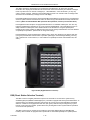
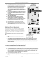
DET (Digital Executive Telephone)
The DX-80 has one model digital telephone. The Digital Executive Telephone is equipped with a half-duplex
speakerphone for hands-free conversations and has a two-row by sixteen column (32-character), dot-matrix,
Super Twist, Liquid Crystal Display (LCD). Directly under the LCD are three Interactive Buttons to enhance
system features operation. During the various features operations these Interactive Buttons take-on
functions to aid in feature use.
The Super Twist LCD eliminates the need for contrast adjustment and enhances angled viewing position
clarity of displayed data. Since the DX-80 includes Caller ID as a standard feature, the LCD also enables
every designated ringing extension to receive Caller Identification* data for incoming CO line calls. (*Note:
This feature requires a subscription from the servicing telephone company.)
P7290 IMM
1-11
DX-80 INSTALLATION AND MAINTENANCE MANUAL
The display provides a visual reference to call progress and call duration, as well as time and date
information. The display also enables the user to send and receive visual advisory and callback messages.
Users may select from six “canned” messages (i.e., “IN A MEETING,” “OUT OF OFFICE”), or they may
create a custom message. Calls from other DX-80 telephone users to an extension with a message active
will receive the visual advisory message on their LCD display.
Each digital speakerphone has thirty (30) Programmable Feature Buttons to aid the user by providing direct
access to system features and resources. There are also three (3) Interactive Buttons and 8† fixed function
buttons. (†Note: the Volume Button Bar represents two operations; volume up and volume down.)
Each Digital Executive Telephone is equipped standard with a 2.5 millimeter headset jack. The user may
toggle his speakerphone operation into an out of a special “Headset Mode”. This mode allows the user to
easily activate the headset jack via the ON/OFF button as an alternative to using the speakerphone.
Headset mode is easily enabled or disabled so that the user may quickly select between use of the headset
or speakerphone operations. (Must be idle to change this setting.)
Each speakerphone is also equipped with a Status Lamp to aid in user operations. The lamp is dual color
(red / green) and indicates various modes of operation. (Messages / Voice Messages Waiting, Incoming
calls - distinctive for CO and intercom, in-use indication for speakerphone mode and headset mode, and
others.)
Figure 8: DET (Digital Extension Terminal)
DSS (Direct Station Selection Terminal)
The DSS Console is a digitally interfaced component of the DX-80. It connects to the system via any
available digital port (408M/E or DPM8 digital port). The DSS is equipped with 60 Programmable Buttons. 12
of these buttons are intended for features code storage only and do not have LED indications associated
with them. 48 buttons are equipped with dual color (red / green) LEDs and may be assigned any system
Feature Code or Directory Number. (These buttons may be assigned for either system features operations
or CO line access operations.)
The DSS Console may be mounted in two positions (Lower Profile Desk Position and Wall Mounted
Position). DSS Consoles are programmed to operate with an associated speakerphone. Speakerphones
P7290 IMM
1-12
DX-80 INSTALLATION AND MAINTENANCE MANUAL
may be assigned up to 4 DSS Consoles each if required. The maximum DSS Consoles supported by the
DX-80 is 12. Each equipped DSS Console requires one digital port therefore the total number (system
capacity) of speakerphones possible is reduced by one for each DSS console installed.
Figure 9: Direct Station Selection Console (Not available at the time of printing)
P7290 IMM
1-13
DX-80 INSTALLATION AND MAINTENANCE MANUAL
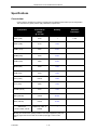
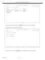
Specifications
Current draw:
Use this chart to calculate the Amphour requirements of the DX-80 system based upon its configuration.
This information is typically used to apply UPS battery requirements.
Component
Current Draw
(Amps)
@ 117 VAC
Quantity
Extended
Total Amps
KSU1 (7201)
0.18A
1
0.18A
KSU2 (7202)
0.17A
1 max.
COM4 (7210)
0.02A
2 max.
DPM8 (7220)
0.01A
4 max.
APM4 (7230)
0.08A
3 max.
MDM (7249)
0.01A
1 max.
AAM (7240)
0.01A
1 max.
PC-8 (7243)
0.015A
1 max.
FL-4 (7241)
0.02A
1 max.
FL3HR (7241E)
0.01A
1 max.
DET (7260-00)
0.016A
48 max.
DSS (7266-00)
0.016A
12 max.
0.02A every 100 ft. of
24AWG
?
Station wire:
per DET, DSS, and IST
Multiply the unit times the quantity installed in the subject application (site) and
add the right column for the total current draw (Amps) @ 117VAC for this
site……
P7290 IMM
1-14
DX-80 INSTALLATION AND MAINTENANCE MANUAL
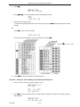
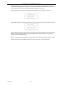
System criteria and capacity:
Time Slots:
PCM - 32 time slots x 4 Highways (128 voice
channels)
TDM 64 Time Slots (data processing)
Customer Database memory protection
300 hours via on-board lithium battery (no charging
required)
Ports:
CO/PBX/Centrex Lines
16
Digital Stations
48
Standard Single Line Telephones
16 (Note: 32 total possible Digital extensions in this
configuration.)
DTMF Receivers:
One dedicated per single line telephone port.
DTMF Senders:
Unlimited. (DTMF signal generation is derived from
the core system tone resource. Tone combinations
are available as needed.)
Tone Detectors: (Used to monitor call
progress tones; Busy Tone, Ring-back Tone,
etc.)
2 (Shared for advanced call processing system
features; DISA, ECF, ABR. etc.)
Contacts:
1 LBC can be programmed as associated to a CO
line or dialed by an extension to actuate the contact.
Conference circuits:
8 - 4 party conference circuits.
DISA circuits:
Any number of CO lines may be programmed for
DISA operation. (AAM required for operation.)
System Attendants:
1Attendant + 1 Alternate per Tenant Group
Tenant Groups
3
UCD/Hunt Groups:
24
Members per group:
24
Group Types:
UCD or Voice Announcer
Hunting Method:
Linear, All Ring or Distributed
Voice Mail Groups:
1 per Tenant (uses 1 UCD Group per VM system)
Members (ports):
24
Integration Method:
Digital (ICD Voice) and In-band (for other)
VM Message Waiting:
#96 + station number to turn VM button LED on.
#*96 + station number to turn VM button LED off.
VM Control codes:
Disconnect Digit(s): 8 digits max.
Subscriber Calling via Intercom: 4 digits max.
Transfers to VM : 4 digits max.
Busy Forward: 4 digits max.
No Answer Forward: 4 digits max.
Direct Call Forward: 4 digits max.
CO Line Recall: 4 digits max.
CO Line Ringing: 4 digits max.
UCD Overflow: 4 digits max.
Record Digits for Voice Recorder function: 4 max.
Delete Digits: 4 digits max.
Suffix for transferred calls: 2 max.
CO Line Loop Current sensing:
P7290 IMM
Interrupt programmable from 50ms to 2500ms.
1-15
DX-80 INSTALLATION AND MAINTENANCE MANUAL
Paging:
8 Internal Page Extension Groups
1 External Page Port
1 Internal All Call
1 System (Internal/External) All Call
Speed Dialing:
1000 total bins, dynamically allocated.
200 bins at default allocated for system-wide use.
20 bins at default allocated for extension use
(extensions 101-148 only) (50 possible per extension)
16 digits maximum per bin.
Last Number Redial:
16 digits per station
Save Number Redial:
16 digits per station
User Saved Number (Memo Pad):
20 digits per station
Callback request per station:
1
Camp On by a busy station:
1
Stations Camped on to a station:
1
Stations Camped on to a busy line:
1
Message - Executive Notification:
6 preprogrammed
1 personal per station
Message - Executive Preprogrammed:
6 preprogrammed
1 personal per station
Message Waiting:
40 simultaneous maximum per system (does not
affect VM message indications)
Name in Display:
1 per station, 7 characters max.
Class Of Service (COS):
8 (0-7) per Day, 8 (0-7) per Night
Toll Restriction To/From Tables:
100 Tables per tenant, 10 digits per entry, Day and
Evening COS assignable per entry per CO Line and
Extension.
Forced Verified Account Codes:
600 codes, 2-8 digits max., each assigned a COS
Unverified Account Codes:
8 digits max.
Call Pick Up Groups:
8 Extension Groups.
Station Lock Password:
4-8 digits per extension.
CDB Programming Password:
8 digits (“________” at default).
System Reminder Alarm:
8 time settings per Tenant Group.
Station Alarm:
1 per station repeating or one time.
Ring Schemes:
8
Distinctive Ring Tones:
8 per station.
External Call Forward:
Via Extension Call Forward settings.
Electrical data:
Electrical Specifications
AC Power source:
Dedicated 117/230vac + 15%, 47-63Hz single phase
Power consumption:
1.5A maximum @ 120vac (180 watts)
Power Supply fuse:
AC input:
2A 250v
DC output:
1A 125v
Idle Channel Noise
-74 dB
Cross Talk Attenuation
75 dB (@ 1kHz)
P7290 IMM
1-16
DX-80 INSTALLATION AND MAINTENANCE MANUAL
Electrical Specifications
Ringing Sensitivity
40v RMS 25 Hz
Ringer Equivalence Number
1.5
CO Line Signaling
DTMF amplitude (-5 dB,-7 dB) +- 2 dB, @ approx. 2
Vpp
Pulse Dialing ratio 60/40 @ 10 PPS
Music source / Background Music
0 dBm at 600 ohm input impedance
1/8th inch phono jack
Contact rating (Option Module LBC):
1A @ 30VDC
0.5A @ 90VAC 30Hz
1/8th inch phono jack
External Page Port
0 dBm at 600 ohms
1/8th inch phono jack
Environmental data:
Environmental Specifications
o
o
o
o
Operating Temperature:
0 to 40 C, 32 to 95 F
Recommended Operating Temperature:
70 to 78 F
Storage Temperature:
32 to 104 F
Operating Relative Humidity:
5% to 90% (non-condensing)
Heat Dissipation (BTU):
300
o
o
o
o
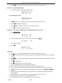
Unit (Component) detail:
Unit Specifications
Part
Number
Description
Dimensions:
7201/7202
KSU1/KSU2
L
460 mm
18.4 in.
W
270 mm
10.8 in.
H
105 mm
4.2 in.
L
210 mm
8.25 in.
W
138 mm
4.5 in.
H
18 mm
¾ in.
L
210 mm
8.25 in.
W
138 mm
4.5 in.
H
18 mm
¾ in.
L
210 mm
8.25 in.
W
138 mm
4.5 in.
H
18 mm
¾ in.
L
210 mm
8.25 in.
W
138 mm
4.5 in.
H
18 mm
¾ in.
L
210 mm
8.25 in.
W
138 mm
4.5 in.
H
21 mm
7/8 in.
L
210 mm
8.25 in.
7200
7248
7210
7220
7230
7240
P7290 IMM
CPM Central Processor Module
408M Standard 4 CO Line x 8 Digital
Extension Module
COM4 Central Office Module – 4 Port
DPM8 Digital Port Module – 8 Port.
APM4 Analog Port Module – 4 Port.
AAM Automated Attendant Module
1-17
Weight
4.0Kg
0.4Kg
0.4Kg
0.3Kg
0.4Kg
1.2Kg
1.7Kg
DX-80 INSTALLATION AND MAINTENANCE MANUAL
Unit Specifications
7241
FL-4
7241E
7243
FL3HR
PC-8
7249
7266-00
138 mm
4.5 in.
H
21 mm
7/8 in.
L
210 mm
8.25 in.
W
138 mm
4.5 in.
H
21 mm
7/8 in.
L
210 mm
8.25 in.
W
138 mm
4.5 in.
H
21 mm
7/8 in.
L
210 mm
8.25 in.
W
138 mm
4.5 in.
H
21 mm
7/8 in.
L
234 mm
9.36 in.
W
188 mm
7.52 in.
H
64.5 mm
2.58 in.
DET – BK
L
230 mm
9 in.
Digital Executive Telephone – Black
(LCD Speakerphone)
W
182 mm
7.25 in.
H
140 mm
5.5 in.
DSS Console – Black
L
241 mm
9.5 in.
W
202 mm
8 in.
H
93 mm
3.75 in.
MDM Modem Module
7260-00
W
0.5Kg
0.3Kg
1.7Kg
1.2Kg
1.7Kg
1.7Kg
Wiring data:
Maximum Cable Length
Digital Key Telephone
26 AWG - 255m (850 ft.)
(Distance measures in linear feet of cable from KSU to DET.)
24 AWG - 425m (1416 ft.)
22 AWG - 700m (1983 ft.)
Standard Single Line Telephone
26 AWG - 195m (650 ft.)
(Distance measures in linear feet of cable from KSU to IST.)
24 AWG - 340m (1133 ft.)
22 AWG - 476m (1586 ft.)
Signaling (Central Office-PSTN) data:
Dialing Specifications
DTMF Dialing mode:
Frequency deviation:
Rise time:
+ 1%
3ms
Duration of DTMF signal:
programmable 50-150ms (70ms default)
Inter-digit time:
programmable 50-150ms (70ms default)
VM Port DTMF duration:
programmable 60-150ms (120ms default)
VM Port Inter-digit time:
programmable 60-150ms (120ms default)
Pulse Dialing mode:
Pulse dial rate:
Pulse Make/Break ratio:
P7290 IMM
10 pulses per second
60/40
1-18
DX-80 INSTALLATION AND MAINTENANCE MANUAL
Regulatory data:
FCC Registration Numbers
For systems configured for Key System operation (each CO line appears
on its own dedicated button).
D6XTAI-40144-KF-T
For systems configured for hybrid operation (CO lines may be accessed
by dial codes and Pool/Loop buttons).
D6XTAI-40145-MF-T
Signaling (internal) data:
Audible Signals
Signal
Frequency
Cadence
Scheme 0
N/A
300ms On, 400ms Off, 300ms On, 4 seconds Off
Scheme 1
N/A
1 second On, 3 seconds Off
Scheme 2
N/A
1 second On, 3 seconds Off
CO Line Ringing:
Scheme 3
follows ring cadence of Ring Scheme selected
Scheme 4
follows ring cadence of Ring Scheme selected
Scheme 5
follows ring cadence of Ring Scheme selected
Scheme 6
Scheme 7
follows ring cadence of Ring Scheme selected
-SLT bell-
follows ring cadence of Ring Scheme selected
Scheme 0
N/A
1 second On, 3 seconds Off
Scheme 1
N/A
1 second On, 3 seconds Off
Scheme 2
N/A
300ms On, 400ms Off, 300ms On, 4 seconds Off
Distinctive 1
Distinctive 2
Distinctive 3
Distinctive 4
SLT
Intercom Ringing:
Scheme 3
follows ring cadence of Ring Scheme selected
Scheme 4
follows ring cadence of Ring Scheme selected
Scheme 5
follows ring cadence of Ring Scheme selected
Scheme 6
follows ring cadence of Ring Scheme selected
Scheme 7
-SLT bell-
follows ring cadence of Ring Scheme selected
Distinctive 1
Distinctive 2
Distinctive 3
Distinctive 4
SLT
Message Wait Callback
P7290 IMM
follows ring cadence of Ring Scheme selected
1-19
DX-80 INSTALLATION AND MAINTENANCE MANUAL
MTBF (Mean-Time Between Failure) data:
Mean-Time Between Failure Analysis
System components
Cabinet Assembly
86.0
Power Supply Unit
170.0
CPM
2915.7
408M
11407.3
DPM8
3560.8
COM4
6146.5
APM4
6860.2
MDM
761.0
AAM
2337.3
Method:
1.
Use the figures above for each unit installed (or to be
installed) and calculate the total for this system
configuration.
2.
Use the total from step 1 in place of the variable “x” in the
formula at the right to calculate MTBF for this system
configuration.
P7290 IMM
1-20
(1 ÷ x)(10 ) = MTBF hours
9
DX-80 INSTALLATION AND MAINTENANCE MANUAL
2. Installation
Proper installation of the Comdial DX-80 will assure optimum system operation and the best overall experience for
the users of the DX-80 telephone system. Since the DX-80 system provides communications functions for its users,
following these installation guidelines is required. Doing so will streamline the process and reduce the potential of
experiencing problems while bringing the DX-80 on-line.
Installation Outline
1.
Plan the installation, including the Key Service Unit (KSU1 or KSU1 & KSU2) and main distribution frame (MDF)
location, station locations, cable runs, and optional equipment.
2.
Assemble the correct tools and supplies. (Telephony tools of the trade. UTP telephony grade cable/wiring.
Miscellaneous telephony hardware; 66 blocks, modular wall jacks, etc.)
3.
Run DX-80 extension cable/wiring for speakerphones, DSS Consoles and analog devices (FAX machines,
modems, etc.) from the MDF to each location. (Wiring topology is referred to as “star-wiring” configuration; no
cable should loop from one telephone location to another.)
4.
Run cable/wiring to any optional equipment, such as external paging equipment, loud bell signaling devices,
music sources, etc.
5.
Mount the MDF backboard and attach the “punch-down” (“66”) terminal block(s) on the backboard. This
documentation adheres to traditional installation practices of telephony equipment using a dedicated MDF with
66 block wiring field to promote full serviceability of the system and connections using proven techniques.
Alternately, the extension cable/wiring may be routed directly into the DX-80 KSU1/KSU2 housing for
connection directly to the appropriate interface module (408M, DPM8, APM4, COM4, CPM). If extension cables
are routed into the KSU, each will require termination of one cable pair into standard crimping modular
connectors. This method is not recommended due to the inherent lack of serviceability once compete.
6.
Terminate extension cables on modular jack assemblies at the terminal locations.
7.
Mount the KSU(s) on the MDF backboard. Mounting template provided.
8.
Ground the KSU1 (and KSU2 if applicable) to a known “good” earth ground.
9.
Install optional expansion modules (COM4, DPM8, APM4) inside the KSU as required.
10. Install optional features modules (AAM, VP1, VP2, VP3, MDM) inside the KSU as required.
11. Route telephone and CO line port interface connections through the appropriate KSU opening (lower left corner)
and connect to them to the interface port. The four pair modular plug pre-terminated DX-80 cable can be used to
aid in this requirement (PN-724PR).
12. Route ancillary device cabling through the appropriate KSU1 opening and terminate as required (music source,
printer/computer for SMDR, external paging equipment, etc.)
13. Cross-connect the CO lines and extension ports to extension cables on the corresponding punch-down
terminal block.
14. Install the terminal instruments and any optional terminal equipment, such as headsets or single line telephones.
15. Move the Cold-Start/Normal (RAM memory battery backup) strap from the “Cold Start” position to the
“Normal” position. This critical step is detailed in the “Power Up Initialization” topic at the end of this
chapter.
16. Plug the AC power cord into the dedicated AC outlet (or UPS if system battery backup support is required) and
power up the DX-80 system by operating the AC power switch to the “ON” position.
17. Observe the power/peripheral processor heartbeat LED for flashing status after 10-20 seconds. This indicates
that the main peripheral board is active and that its processor is running. During the first power-up sequence
(Cold-Start strap moved to Normal position), default data is loaded which can take as long as 2 minutes. The
main processor LED located on the Central Processor Module may be monitored during the boot-up stage to
determine when the system is operational. A series of flash rates occur during this process. When default is
successfully loaded or whenever the system becomes functional following a power failure, the CPM Heart-beat
LED maintains a consistent fast flash rate. The terminal equipment should be operational at this time.
P7290 IMM
2-1
DX-80 INSTALLATION AND MAINTENANCE MANUAL
18. Refer to the specific feature descriptions section of this manual for operation and programming information.
Site Planning
Establishing Suitable Environmental Conditions for the System
•
Place KSU1 (and KSU2 if applicable) within 5 feet (1.5 meters) of an isolated, dedicated, 105-125VAC, 57-63Hz,
15A, single-phase commercial power source.
Note: This must be an isolated, dedicated AC circuit for proper operation. All three wires (power, neutral, and
ground) must be run separately from the outlet to the breaker panel without being bonded to any other wire or
circuit. Do not plug any other equipment into this outlet. To maintain the protection provided by the isolated,
dedicated circuit, the length of the AC power cord limits the distance between the KSU and the outlet. Do not use
an extension cord.
•
To protect the system from lightning damage or other AC power line disturbances, a surge protector should be
installed.
•
Select the KSU location to minimize cable run length. Terminal Equipment connected to the system must not
exceed specified limits (see overview Specifications).
•
The KSU location should not be exposed to direct sunlight, high humidity, heat, dust, or strong magnetic fields
(such as those generated by heavy motors, copy machines and some kitchen appliances).
IMPORTANT! The DX-80 system must be installed in a climate controlled environment. When equipped with
optional voice processing modules, the system takes on the characteristics of a mechanically driven computing
storage device. (A computer with a hard disk drive.)
This equipment cannot function in environments above 95 degrees Fahrenheit ambient temperature.
•
The MDF should consist of a 3/4-inch plywood backboard large enough to mount all hardware and equipment
allowing all components ample space for adequate ventilation and servicing. Allow additional room for external
apparatus, if used.
•
For cooling purposes, ample air space (at least four inches on the top, bottom, left and right sides) should be
provided for the KSU.
•
SMDR/SMDA output device(s) must be placed within 50 feet (15 meters) of the KSU (limited by RS-232C
standard wiring practices).
The equipment should be located in a climate-controlled room adhering to the Environmental
Specifications listed in the Overview section of this manual.
Note: When installing the KSU and station instruments, allow a sufficient margin for error in case of air
conditioning failure, routine maintenance, plant shutdown, etc. As a general rule, if conditions are suitable for
office personnel, they are also suitable for KSU and terminal equipment operation. A properly controlled
environment will help to extend the operating life of the equipment.
From UL 1459, a product safety specification governing telephone equipment:
•
Never install telephone wiring during a lightning storm.
•
Never install telephone jacks in wet locations unless the jack is specifically designed for wet locations.
•
Never touch non-insulated telephone wires or terminals unless the telephone line has been disconnected at the
network’s interface.
•
Use caution when installing or modifying telephone lines.
Tools and Supplies
•
Assemble the correct supplies and tools to install the Comdial DX-80 as it is intended.
•
Use UTP (Unshielded, Twisted-Pair) three or four pair (recommended) cable to run from the MDF (Main
Distribution Frame) to all extension terminals (speakerphones, DSS Consoles and analog devices). Digital
terminals only need one twisted pair to operate. (Additional pairs are always recommended to allow for future
potential uses.)
P7290 IMM
2-2
DX-80 INSTALLATION AND MAINTENANCE MANUAL
•
Six conductor modular jack assemblies for all station instruments (recommended).
•
Standard punch-down terminal block(s) (66M1-50 type) as required.
•
Four or six conductor crimping modular plug assemblies for each port interface. Or, a better choice is to use
DX-80 PN “RJ11-4P” cables to extend DX-80 ports to the MDF.
•
AC voltage surge/spike protector.
•
Standard telephone hand tools and mounting hardware for the KSU(s), MDF backboard, punch-down terminal
block(s), modular jack assemblies for CO lines, etc.
Preparing the Main Distribution Frame
The Main Distribution Frame (MDF) is the point at which the KSU, terminal equipment, CO lines, and miscellaneous
equipment are connected to one another. It is extremely important that the connections be made carefully and
accurately.
Assembling the MDF
Follow these steps to assemble the MDF.
1.
Mount a sufficiently sized 3/4-inch plywood backboard at the proper location for use as the MDF termination
and equipment mounting board.
2.
Plan the layout of all required MDF components allowing for expansion. This may include: KSU1, KSU2,
66M1-50 termination blocks, cable fastening hardware, and miscellaneous third-party communications
equipment (paging equipment, etc.)
3.
Locate the Telco provided CO/Centrex lines at the DEMARC (Demarcation) and extend them to the MDF
location.
4.
Locate a suitable, known-good earth ground preferably within 10 feet of the MDF and route a #10AWG
grounding wiring from the point of grounding to the MDF for connection to the KSU.
5.
Install all terminal device wiring (telephone cabling) and route to the MDF location for termination.
6.
Mount all equipment and termination hardware as required to complete interconnection of terminal devices
and KSU modules.
KSU Components and Installation
The Key Service Units are shipped in their own protective master carton and contain the following
components:
KSU1
•
1 mounting template
•
1 System Installation & Features Manual
•
1 Quick Start-up Guide
•
1 Programming Guide
•
Standard 408M (Module) equipped with 8 digital extension ports, 4 CO Line ports, and 1 CO Line PFT
(Power Failure Transfer) port.
•
Standard CPM (Central Processor Module)
•
Standard APM4 (Analog Port Module – 4 port)
KSU2
•
1 mounting template
•
Standard Expansion Cabinet 408M (Module) equipped with 8 digital extension ports, 4 CO Line ports,
and 1 CO Line PFT (Power Failure Transfer) port.
Open the carton(s) and verify that all items are complete and undamaged. Remove all packing material and
store for future use in the event that return shipment is required.
P7290 IMM
2-3
DX-80 INSTALLATION AND MAINTENANCE MANUAL
Mounting the KSU
Follow these instructions to mount the KSU.
1.
Select a suitable location for the KSU1 considering that the expansion (KSU2) may be installed at the same
time or sometime in the future. KSU1 and KSU2 may be mounted such that they are side-by-side or
mounted one above the other.
Side-by-side
One above the other
2.
Using the mounting template as a guide, mark the two (2) mounting screws locations on the MDF
backboard.
3.
Pre-drill two (2) screw holes and install the two, pan-head No. 10 screws (supplied) into the backboard with
a regular screwdriver. The screw heads should protrude about 1/4-inch from the backboard plywood
surface.
4.
Lift the KSU over the two screws allowing the screws to extend into the KSU slotted mounting holes. As the
KSU is allowed to rest in place on the mounting screws it will slip over the screw shanks until the top of the
slot is reached. Properly installed, the KSU power transformer (where the KSU AC power cord is located) is
positioned in the upper left corner. The power switch and Power/Heartbeat LED are positioned at the left
side of the KSU toward the bottom.
Note: It is very important that the KSU be correctly mounted to allow proper power supply heat
dissipation. KSU1 and KSU2 are intended to be wall mounted only.
5.
Ground the KSU. Extend the earth ground #10 wire into the KSU opening at the lower
left corner of the KSU. Terminate the grounding wire onto the ground lug provided there.
Ground LUG
P7290 IMM
2-4
DX-80 INSTALLATION AND MAINTENANCE MANUAL
KSU Wiring
Note: System power should be OFF before plugging in the station cable or while servicing port connections
at the punch-down block (66M1-50). (Although each port is over-current protected, unnecessary shorting
should be avoided.)
The 408M/E, APM4 (Analog Port Module), COM4 (CO Line Module) and DPM8 (Digital Port Module) are equipped
with RJ-11 modular jacks for each of the interfaced ports. This connection scheme allows for two methods of
installation. The first method (traditional “MDF”) is recommended whenever possible to allow for maximum
serviceability.
MDF (Main Distribution Frame)
Whenever the various ports of the DX-80 are extended to the MDF, modular ended cables must be
extended from the KSU module port to the MDF connection block. The installer has many choices when
completing these connections and it is left to the installer’s discretion to use the most suitable industry
standard wiring practice for the particular installation.
Note:
Whenever field-crimped modular connectors are used, USE A QUALITY
CRIMPING TOOL to fasten the modular connector to the cable pair.
Use a cheap tool…expect bad connections!
Many third-party vendor products are available to aid in this installation procedure. The examples below are
readily available at communications equipment / accessories supply houses. Although this example denotes
®
product of The Siemon Company , the installer is urged to investigate the various products available and
make decisions for use based on his / her own assessment. (Comdial is not responsible for the performance
of any product provided by a third-party (outside) vendor.)
The examples in the following chart are 25 pair (UTP), USOC, 24 AWG cables pre-fitted with modular
®
connectors on one end of the cable and a male or female AMP type connectors on the other end for
®
termination on a specially equipped, 66-block with mating AMP type connector.
The Siemon Company® Hydra Cable Assemblies
Product Number
Length (feet)
Wiring Scheme - End 1
HYD-F-24U1-03
3
25-Pair, Female
HYD-F-24U1-07
7
25-Pair, Female
HYD-F-24U1-10
10
25-Pair, Female
HYD-M-24U1-03
3
25-Pair, Male
HYD-M-24U1-07
7
25-Pair, Male
HYD-M-24U1-10
10
25-Pair, Male
When the KSU wiring is complete, each port of the DX-80 system may individually be isolated for
independent maintenance needs. The wiring in place is then terminated onto a 66M1-50 – connector
block(s). From this connector block - ports are extended to station cables using standard jumper wire.
No MDF
Since the Comdial DX-80 is equipped with RJ-11 interfaces for all port connections, it is possible to route
station cables into the KSU directly without use of 66M1-50 connector blocks. Using quality modular
connectors and crimping tool, each terminal cable can be connected directly to the port required. This
method of installation although initially convenient and less expensive, is not recommended due to the
inherent lack of serviceability.
P7290 IMM
2-5
DX-80 INSTALLATION AND MAINTENANCE MANUAL
Regardless of the method used, station / MDF cables are routed out of the
KSU through the opening at the lower left of the KSU housing. A cable
restraint clamp is provided and may be used to secure cables exiting the
KSU.
Typical MDF Installation
The example install below illustrates a two-cabinet installation using the MDF installation method.
Dedicated
AC Outlet.
(Dedicated
means that
this AC
outlet has
no other
equipment
connected
on this
circuit
breaker.
“Station”
Cables from
telephones
DX-80
DX-80
KSU1
KSU2
#10
AWG
ground
Paging
Equipment,
other
ancillary
(third-party)
equipment.
66M1-50 blocks
KSU
terminations
66M1-50
blocks
66M1-50
blocks
ancillary
equipment
(Paging,
music
sources, etc.)
“Station”
phone cable
terminations
66M1-50
The 66M1-50 is split into a left half and right half
for wiring terminations.
Each row is conductive between the left two
columns and the right two columns. This is the
source of the term “Split 50.”
Terminate cable pairs from the KSU and from
telephone locations on outer column pins, one lead
only per pin.
NEVER terminate two wires on one pin!
This is referred to as “double-punching” and
causes poor connection of wires on the terminal.
(Note: When used with “Bridging Clips,” the Split
50 block can be used to isolate trouble in wiring.)
P7290 IMM
2-6
DX-80 INSTALLATION AND MAINTENANCE MANUAL
KSU Components
KSU1 408M and KSU2 408E
The 408M module is installed at the factory into KSU1. Although this module has the same port
configuration as the 408E, they are not interchangeable. Each 408M and 408E is equipped with 4 CO Line
Ports, 1 Power Failure Port, and 8 Digital Extension Ports. See the following diagram to locate the various
ports provided on the 408M/E.
The 408M/E is also the interface point for the various add-on modules of the DX-80 system. All peripheral
modules connect to the DX-80 via the 408M/E. See Diagram X as a reference of the various interface
connectors.
APM4 ribbon
connector (J4)
COM4 ribbon
connector
408M: CPM ribbon cable
Voice Processor
Power Connector
408E: CPM connector cable
(approximately one meter
long to extend out of KSU2
into KSU1)
Extension Expansion module
connectors.
DPM8 or APM4
Eight Digital
Extension Ports.
KSU1: 101-108
KSU2: 125-132
Power Failure
Transfer Port.
KSU1: 740
KSU2: 748
J2
Four CO Line
circuits.
KSU1: 740~743
KSU2: 748~751
J3
Replacing a 408 M / E
Occasionally, when instructed to do so by a Comdial technical support representative, it may be necessary to remove
a 408M or 408E and replace it in the field. Do this by following the steps below.
1.
Be sure that the entire system is turned off.
2.
Remove the KSU cover (four screws at each corner).
3.
Connect grounded wrist strap to a suitable earth ground. (If a grounded wrist strap is not available, bleed
any static charge from your body before touching circuit modules by touching the gold-painted surface of the
inside of the KSU cabinet. If the KSU is properly grounded this will momentarily discharge static electricity
from your body. NOTE: A GROUNDED WRIST STRAP IS THE ONLY METHOD OF ASSURING THAT
STATIC CHARGE DOES NOT DAMAGE CIRCUIT MODULES.)
4.
Remove all circuit modules from the KSU cabinet. All modules are fastened in place using standoff
hardware. Notice: be sure that stand off placement is re-constructed when the various modules are re-
P7290 IMM
2-7
DX-80 INSTALLATION AND MAINTENANCE MANUAL
installed. (APM4 modules must be installed using 2.5 cm stand offs. These specific length standoffs are
steel color for easy identification.)
5.
Install the replacement 408M/E using the brass (2.0cm) standoffs removed from the original.
6.
Install all other remaining modules in the order that they were removed, connecting them to the appropriate
408M/E connector.
7.
Reconnect CO Line and Station cabling connections as required.
NOTE:
The FCC requires that wiring of CO Lines into a Key Service Unit be separated from
wiring of station apparatus into a Key Service Unit. Therefore the installer must use a
separate cable for wiring of stations and CO Lines.
8.
Replace the KSU cover and secure with cover screws.
9.
Restore KSU power when all wiring is complete.
KSU Assembly – Add-on Modules
Whenever the DX-80 system is expanded, a module must be installed into one of the KSU cabinets. Modules are
connected to the various connectors on the 408M/E. Modules are mounted using standoff posts. Two standoff post
sizes are used in the DX-80. The APM4 modules must be installed using the nickel color 2.5 cm standoffs. All other
modules use brass color 2.0 cm standoffs. Proper use of standoff is imperative to assure proper system operation.
408E Connector
MDM
Connectors
408M Connector
AAM Connector /
VP Connector
CPM
AAM Connector
SLOT 4
SLOT 3
SLOT 2
SLOT 1
P7290 IMM
SLOT 5
408 M / E
2-8
SLOT 1
DX-80 INSTALLATION AND MAINTENANCE MANUAL
Adding a DPM8 (Digital Port Module – 8 port)
Two DPM8 (Digital Port Module, 8-port) modules can be added to each KSU of the DX-80 system. These modules
expand the DX-80 system extension capacity to a maximum of 24 digital ports in each KSU (48 total digital ports).
DPM8’s are installed by connection to the 408M/E via the Extension Expansion module connectors (“J2” and “J3.”)
These connectors have the logical system address of SLOT 2 and SLOT 3 in both Cabinet 1 (KSU1-408M) and
Cabinet 2 (KSU2-408E). (APM4 and DPM8 modules may be connected to the system via these two connectors.)
DPM8’s are installed using four (4), 2.0 cm brass color standoffs included with the DPM8 module.
DPM8
DPM8
J2 J3
DPM8 Extension Number Matrix Per Installed Location
KSU Connector Used
Extension Numbers in
KSU1
Extension Numbers in
KSU2
J2 Extension Expansion
109,110,111,112,
113,114,115,116
133,134,135,136,
137,138,139,140
J3 Extension Expansion
117,118,119,120,
121,122,123,124
141,142,143,144,
145,146,147,148
DPM8 Installation Procedure
1.
Be sure that the entire system is turned off.
2.
Remove the KSU cover (four screws at each corner).
3.
Connect grounded wrist strap to a suitable earth ground. (If a grounded wrist strap is not available, bleed
any static charge from your body before touching circuit modules by touching the gold-painted surface of the
inside of the KSU cabinet. If the KSU is properly grounded this will momentarily discharge static electricity
from your body. NOTE: A GROUNDED WRIST STRAP IS THE ONLY METHOD OF ASSURING THAT
STATIC ELECTRICITY DOES NOT DAMAGE CIRCUIT MODULES.)
4.
Remove the DPM8 module from the packaging and locate the four brass-color standoffs packaged with the
module.
5.
Position the DPM8 over the left-hand side of the 408M/E and any other extension modules already installed.
(When installing DPM8 modules, it is recommended that they be installed closest to the 408M/E. That is, if
P7290 IMM
2-9
DX-80 INSTALLATION AND MAINTENANCE MANUAL
an APM4 module is installed move it outward (toward cabinet cover) and install the add-on DPM8 first then
reinstall the APM4.)(Extension modules are always installed on the left-hand side, in the KSU.)
6.
Use the four brass-color standoffs supplied with the DPM8 to secure the DPM8 in position.
7.
Connect the DPM8 ribbon cable to the 408M Extension Expansion Module Connector closest to the DPM8.
Press firmly (but not forcefully) on the connector to secure a good connection.
8.
Make connections to the 8 digital ports as required.
NOTE:
9.
The FCC requires that wiring of CO Lines into a Key Service Unit be separated from
the wiring of station apparatus into a Key Service Unit. Therefore the installer must
use a separate cable for wiring of stations and CO Lines.
Replace the KSU cover and secure with cover screws.
10. Restore KSU power.
Adding an APM4 (Analog Port Module – 4 port)
One APM4 (Analog Port Module, 4-port) can be added to KSU1 and two APM4’s can be added to KSU2. These
modules expand the DX-80 system extension capacity to a maximum of 8 analog ports in each KSU (16 total analog
ports when used in both KSU 1 & 2).
When adding an APM4 to KSU1, it is installed by connection to the 408M via an available Extension Expansion
module connector (either “J2” or “J3” but not both). These connectors have the logical system address of SLOT 2 and
SLOT 3 in both Cabinet 1 (KSU1-408M) and Cabinet 2 (KSU2-408E). APM4’s are installed using four (4), 2.5 cm
nickel-color standoffs.
When adding APM4 modules to KSU2, one may be installed on either of the Extension Expansion module connectors
and one may be installed on the dedicated APM4 Module Connector. This connector has the logical system address
of SLOT 4 in both Cabinet 1 (KSU1-408M) and Cabinet 2 (KSU2-408E).
APM4
APM4
408M
P7290 IMM
2-10
DX-80 INSTALLATION AND MAINTENANCE MANUAL
Extension Number Matrix Per Installed Location
KSU Connector
used
Extension numbers
in KSU1
Extension Numbers
in KSU2
Notes
149,150,151,152
153,154,155,156
KSU1 analog ports are standard
109,110,111,112
133,134,135,136
APM4 Connector
(SLOT 4)
J2 Extension
Expansion
(SLOT 2)
J3 Extension
Expansion
117,118,119,120
141,142,143,144
Since the profile of the APM4
module is higher than the other
modules, only one Extension
Expansion connector can be
used for APM4 modules.
(SLOT 3)
APM4 Installation Procedure
1.
Be sure that the entire system is turned off.
2.
Remove the KSU cover (four screws at each corner).
3.
Connect grounded wrist strap to a suitable earth ground. (If a grounded wrist strap is not available, bleed
any static charge from your body before touching circuit modules by touching the gold-painted surface of the
inside of the KSU cabinet. If the KSU is properly grounded this will momentarily discharge static electricity
from your body. NOTE: A GROUNDED WRIST STRAP IS THE ONLY METHOD OF ASSURING THAT
STATIC ELECTRICITY DOES NOT DAMAGE CIRCUIT MODULES.)
4.
Remove the APM4 module from the packaging and locate the four nickel-color standoffs packaged with the
module.
5.
Position the APM4 over the left-hand side of the 408M/E and any other extension modules already installed.
(Extension modules are always installed on the left-hand side, in the KSU.)
6.
Use the four nickel-color standoffs supplied with the APM4 to secure the APM4 in position.
7.
Connect the APM4 ribbon cable to the 408M/E Extension Expansion Module Connector closest to the
APM4. Or in KSU2, connect the dedicated APM4 ribbon cable from the 408E to the APM4 module (and
discard the packaged ribbon cable). Press firmly (but not forcefully) on the connector to secure a good
connection.
8.
Make cable/wiring connections to the 4 analog ports as required.
NOTE:
9.
The FCC requires that wiring of CO Lines into a Key Service Unit be separated from
wiring of station apparatus into a Key Service Unit. Therefore the installer must use a
separate cable for wiring of stations and CO Lines.
Replace the KSU cover and secure with cover screws.
10. Restore KSU power.
Adding a COM4 (CO Line Module – 4 port)
One COM4 (CO Line Module, 4-port) can be added to KSU1 and one COM4 can be added to KSU2. These modules
expand the DX-80 system CO Line interface capacity to a maximum of 8 CO Line ports in each KSU (16 total CO
Line ports when used in KSU 1 & 2).
When adding a COM4 to either KSU, it is installed by connection to the 408M/E via the COM4 module ribbon cable.
This ribbon cable has the logical system address of SLOT 5 in both Cabinet 1 (KSU1-408M) and Cabinet 2 (KSU2408E). COM4 modules are installed using four (4), 2.0 cm brass-color standoffs. The COM4 module should always
be installed beneath the CPM module (in KSU1) by first removing that module, installing the COM4 then reinstalling
the CPM. (This is required whenever the PC-8 Voice Processor is installed.)
P7290 IMM
2-11
DX-80 INSTALLATION AND MAINTENANCE MANUAL
COM4
408M
CPM
CO Line Directory Number Matrix Per Installed Location
408M in KSU1
COM4 in KSU1
408E in KSU2
COM4 in KSU2
SLOT 1
SLOT 5
SLOT 1
SLOT 5
740,741,742,743
744,745,746,747
748,749,750,751
752,753,754,755
COM4 Installation Procedure
1.
Be sure that the entire system is turned off.
2.
Remove the KSU cover (four screws at each corner).
3.
Connect grounded wrist strap to a suitable earth ground. (If a grounded wrist strap is not available, bleed
any static charge from your body before touching circuit modules by touching the gold-painted surface of the
inside of the KSU cabinet. If the KSU is properly grounded this will momentarily discharge static electricity
from your body. NOTE: A GROUNDED WRIST STRAP IS THE ONLY METHOD OF ASSURING THAT
STATIC ELECTRICITY DOES NOT DAMAGE CIRCUIT MODULES.)
4.
We recommend installing the COM4 closest to the 408M/E. This means that the CPM must be temporarily
removed then repositioned above the COM4 once it is installed (in KSU1). For KSU2 installation skip step 5
and proceed with step 6.
5.
Remove the installed CPM by removing the four brass standoffs used to secure the board. Retain these
standoffs for later use. Remove the ribbon cable that connects the CPM to the 408M then set aside.
6.
Remove the COM4 module from the packaging and locate the four brass-color standoffs packaged with the
module.
7.
Position the COM4 over the 408M/E (right-hand side) where the CPM was just removed (KSU1).
8.
Use the four brass-color standoffs supplied with the COM4 to secure the COM4 in position.
P7290 IMM
2-12
DX-80 INSTALLATION AND MAINTENANCE MANUAL
9.
Connect the COM4 ribbon cable from the 408M/E to the COM4 connector. Press firmly (but not forcefully)
on the connector to secure a good connection. For KSU2 installation, skip step 10 and proceed to step 11.
10. Reposition the CPM over the installed COM4 and secure using the four brass-color standoffs removed in
step 4.
11. Make cable/wiring connections to the 4 CO Line ports as required.
NOTE:
The FCC requires that wiring of CO Lines into a Key Service Unit be separated from
wiring of station apparatus into a Key Service Unit. Therefore the installer must use a
separate cable for wiring of stations and CO Lines.
12. Replace the KSU cover and secure with cover screws.
13. Restore KSU power.
Adding an MDM (Modem Module)
One MDM (Modem Module) can be added to KSU1. The Modem Module will allow remote access to
the DX-80 telephony system database and Maintenance functions using the PC-DBA utility. (The MDM
does not provide access to the DX-80 DX-SO Voice Mail/AA.)
MDM
At default the MDM directory number is “199.” To establish a connection to the
MDM remotely, call into the system (where the MDM is installed) from the
remote site using PC-DBA. Ask to be transferred to extension 199. When
modem tone is heard, initiate any required keystrokes to link the modems.
Then proceed with usual PC-DBA connection routines (see Database
Administration – via PC-DBA).
The MDM is installed onto designated connectors located on the CPM.
MDM Installation Procedure
1.
Be sure that the entire system (KSU 1&2) is turned off.
2.
Remove the KSU cover (four screws at each corner).
3.
Connect grounded wrist strap to a suitable earth ground. (If a
grounded wrist strap is not available, bleed any static charge from
your body before touching circuit modules by touching the goldpainted surface of the inside of the KSU cabinet. If the KSU is
properly grounded this will momentarily discharge static electricity
from your body. NOTE: A GROUNDED WRIST STRAP IS THE
ONLY METHOD OF ASSURING THAT STATIC ELECTRICITY
DOES NOT DAMAGE CIRCUIT MODULES.)
4.
Locate the CPM at the right-hand side of KSU1 above the 408M
(and COM4 if installed).
5.
Position the MDM over the CPM-MDM connectors as illustrated in the diagram above.
6.
Press firmly (but not forcefully) on the MDM to secure a good connection into the CPM-MDM connectors.
7.
Replace the KSU cover and secure with cover screws.
8.
Restore KSU power.
P7290 IMM
2-13
CPM
DX-80 INSTALLATION AND MAINTENANCE MANUAL
Adding an AAM (Automated Attendant Module)
One AAM (Auto Attendant Module) can be added to KSU1. The AA Module adds automated attendant functionality to
the DX-80 system with 10 integrated announcements. (The AAM does not provide voice mail functions.)
Refer to the specific feature description “Automated Attendant” for information
about announcements and programming CO Lines to be answered by the
AAM.
The AAM is installed onto designated connectors located on the CPM.
AAM
AAM Installation Procedure
1.
Be sure that the entire system is turned off.
2.
Remove the KSU cover (four screws at each corner).
3.
Connect grounded wrist strap to a suitable earth ground. (If a
grounded wrist strap is not available, bleed any static charge
from your body before touching circuit modules by touching
the gold-painted surface of the inside of the KSU cabinet. If
the KSU is properly grounded this will momentarily discharge
static electricity from your body. NOTE: A GROUNDED
WRIST STRAP IS THE ONLY METHOD OF ASSURING
THAT STATIC ELECTRICITY DOES NOT DAMAGE CIRCUIT
MODULES.)
CPM
4.
Locate the CPM at the right-hand side of KSU1 above the
408M (and COM4 if installed).
5.
Position the AAM over the CPM-AAM connectors as illustrated
in the diagram above.
6.
Press firmly (but not forcefully) on the AAM to secure a good connection into the CPM-AAM connectors.
7.
Replace KSU cover and secure with cover screws.
8.
Restore KSU power.
Adding a KSU2 (Key Service Unit-2, second cabinet)
One KSU2 (Key Service Unit-2) can be added to KSU1. The KSU2 adds:
•
•
•
•
•
•
8 (eight) digital DX-80 extension ports
4 (four) CO Line ports
1 (one) Power Failure Transfer port
Extension Expansion connectors for 2 addition DPM8 or 1 APM4
Ribbon cable for one APM4
Ribbon cable for one COM4
KSU2 is connected to KSU1 via a designated connector located on the CPM inside of KSU1.
KSU2 Installation Procedure
1.
Be sure that the entire system is turned off.
2.
Remove the KSU cover (four screws at each corner) on both KSU1 and KSU2.
P7290 IMM
2-14
DX-80 INSTALLATION AND MAINTENANCE MANUAL
3.
“2nd Cabinet
Connector”
Connect grounded wrist strap to a suitable earth ground. (If a
grounded wrist strap is not available, bleed any static charge
from your body before touching circuit modules by touching
the gold-painted surface of the inside of the KSU cabinet. If the
KSU is properly grounded this will momentarily discharge
static electricity from your body. NOTE: A GROUNDED
WRIST STRAP IS THE BEST METHOD OF ASSURING
THAT STATIC ELECTRICITY DOES NOT DAMAGE CIRCUIT
MODULES.)
4.
Locate the long cable attached to the 408E of KSU2 and route
it out of the KSU cabinet into the KSU1 cabinet for connection
on the CPM.
5.
Locate the CPM at the right-hand side of KSU1 above the
408M (and COM4 if installed).
Cable from KSU2-408E
CPM
nd
6.
Position the KSU2 connection cable over the CPM-“2
Cabinet Connector” as illustrated in the diagram above.
7.
Press firmly (but not forcefully) on the KSU2-Cable connector
nd
to secure a good connection into the CPM-“2 Cabinet
Connector.
8.
Replace the KSU cover and secure with cover screws.
9.
Restore KSU power by powering both KSU cabinets at the
same time. (Operate both cabinet power switches to the “ON”
position simultaneously.
Adding a Music Source(s)
Two sources of music can be connected to the CPM of the DX-80
system for use with the features: Music On Hold and Background
Music. (Optionally, an internal musical tune or tone can be used for
callers on hold. When this option is used, the MC1 connector is not
used.)
To select the internal music tune for use on music channel
MC1:
CPM
“MC1” & “MC2”
External Music source
connectors
1.
Remove the KSU cover (four screws at each corner) of
KSU1.
2.
Connect grounded wrist strap to a suitable earth ground. (If
a grounded wrist strap is not available, bleed any static charge from your body before touching circuit
modules by touching the gold-painted surface of the inside of the KSU cabinet. If the KSU is properly
grounded this will momentarily discharge static electricity from your body. NOTE: A GROUNDED WRIST
STRAP IS THE BEST METHOD OF ASSURING THAT STATIC ELECTRICITY DOES NOT DAMAGE
CIRCUIT MODULES.)
3.
Locate the CPM and “MUSIC” option strap.
4.
Move the “MUSIC” option strap (JP30) from the “EXT” (factory position) to the “INT” position.
To install an external music source to either MC1 or MC2 or both:
1.
Remove the KSU cover (four screws at each corner) of KSU1.
2.
Connect grounded wrist strap to a suitable earth ground. (If a grounded wrist strap is not available, bleed
any static charge from your body before touching circuit modules by touching the gold-painted surface of the
inside of the KSU cabinet. If the KSU is properly grounded this will momentarily discharge static electricity
from your body. NOTE: A GROUNDED WRIST STRAP IS THE BEST METHOD OF ASSURING THAT
STATIC ELECTRICITY DOES NOT DAMAGE CIRCUIT MODULES.)
3.
Locate the CPM and the “MUSIC” option strap.
4.
Make sure that the “MUSIC” option strap is in the “EXT” position. (Required for external source to operate on
MC1.)
P7290 IMM
2-15
DX-80 INSTALLATION AND MAINTENANCE MANUAL
5.
Locate CPM the “MC1” and “MC2” connector jacks on the CPM.
6.
Using an eighth-inch mini plug, connect the output of the external music source to
the appropriate MC1 or 2 connector. (At default MC1 is used for Music On Hold.)
This is easily accomplished using a prefabricated mini-plug to mini-plug cable
available at Radio Shack.
7.
Adjust the music volume level at the external music source. When adjusting the music for Music On Hold,
place a call into the system on one of the CO Lines. Place this call on hold so that the external music source
is heard by the calling party (you). Adjust the volume level of the external music source until a desirable level
is reached. (Background Music is then adjusted at the telephone using the instrument volume control.)
Adding an External Pager (paging system)
One port is provided at the CPM of the DX-80 system for use with external paging system apparatus. When DX-80
users dial the external pager code (“777” at default) or dial the Tenant Group All Page code (“400” at default), voice
announcements can be made over the external paging equipment.
The DX-80 External Page port does not provide any amplification.
Interface at the amplifier should be matched to approximately 600
ohms for the best performance.
CPM
External Pager Installation Procedure
1.
Remove the KSU cover (four screws at each corner) of
KSU1.
2.
Connect grounded wrist strap to a suitable earth ground. (If
a grounded wrist strap is not available, bleed any static
External “PAGE”
charge from your body before touching circuit modules by
connector (goes to
external amplifier)
touching the gold-painted surface of the inside of the KSU
cabinet. If the KSU is properly grounded this will
momentarily discharge static electricity from your body.
NOTE: A GROUNDED WRIST STRAP IS THE BEST METHOD OF ASSURING THAT STATIC
ELECTRICITY DOES NOT DAMAGE CIRCUIT MODULES.)
3.
Locate the CPM and “PAGE” connector jack on the CPM.
4.
Using an eighth-inch mini plug, connect the DX-80 Page port to the external
amplifier input.
5.
Adjust the voice volume level at the external paging amplifier. When adjusting the volume level, dial access
to the External Pager port at any DX-80 telephone (“777”). Then adjust the volume control associated to the
amplifier input selected for this purpose.
Adding Loud Bell Control or Gate Control
One “dry-connection” is provided at the CPM of the DX-80 system for use
with external ringing devices or door opening apparatus. The DX-80 can be
programmed to activate the dry contact whenever certain CO Lines ring or
whenever the LBC code is dialed to actuate a door opener.
CPM
Loud Ringing Bell Installation Procedure
1.
Remove the KSU cover (four screws at each corner) of KSU1.
2.
Connect grounded wrist strap to a suitable earth ground. (If a
grounded wrist strap is not available, bleed any static charge from your body before
touching circuit modules by touching the gold-painted surface of the inside of the KSU
cabinet. If the KSU is properly grounded this will momentarily discharge static electricity
from your body. NOTE: A GROUNDED WRIST STRAP IS THE BEST METHOD OF
ASSURING THAT STATIC ELECTRICITY DOES NOT DAMAGE CIRCUIT MODULES.)
3.
Locate the CPM and “BELL” connector jack on the CPM.
P7290 IMM
2-16
“BELL” control connector
(wires to bell and power
supply)
DX-80 INSTALLATION AND MAINTENANCE MANUAL
4.
Using an eighth-inch mini plug, wire the DX-80 BELL contact in series with an external 24vdc power supply
and 24vdc bell or ringing device. Important: Use only 24v or less voltage supply and Direct Current
(dc).
5.
Program LBC operation for CO Line ringing according to CO Line Group
assignments. See Loud Bell Control in the features description section of this
manual.
6.
To control a gate or door:
7.
Remove the KSU cover (four screws at each corner) of KSU1.
8.
Connect grounded wrist strap to a suitable earth ground. (If a grounded wrist
strap is not available, bleed any static charge from your body before touching
circuit modules by touching the gold-painted surface of the inside of the KSU
cabinet. If the KSU is properly grounded this will momentarily discharge static
electricity from your body. NOTE: A GROUNDED WRIST STRAP IS THE
BEST METHOD OF ASSURING THAT STATIC ELECTRICITY DOES NOT
DAMAGE CIRCUIT MODULES.)
9.
Locate the CPM and “BELL” connector jack on the CPM.
10. Using an eighth-inch mini plug, wire the DX-80 BELL contact in series with an
external 24vdc power supply and 24vdc door opening device. Important: Use
only 24v or less voltage supply and Direct Current (dc).
11. Program LBC operation for External Page operation. Door/Gate operation is
accomplished by dialing the External Page code (this code can be
programmed onto an available Flexible Feature Button). See Loud Bell Control
in the features description section of this manual.
Connecting a Serial Cable for PC-DBA
PC-DBA (PC-Database Administration) can be connected the to DX-80 system for use
to set all user database programable features and system operations. (See Database Administration – via PC-DBA.)
This connection is rarely permanent and is typically performed only during routine systems database updates and
changes by a qualified technician. Connection of the PC to the DX-80 is accomplished through the serial data port on
the CPM labeled “PCDBA.” Connection is simplified by means of a straight-through, 9-pin, female to male, serial
cable. (Use Radio Shack model 26-117B for good results.)
Connection to the PC is made via an available 9-pin serial port connector that is designated as COM1 or COM2 in the
PC configuration.
Once the cable is linked between the PC and the DX-80 CPM, PCDBA port, PC-DBA can be used to program the
DX-80 system and backup the user database.
Serial Cable Installation Procedure
Follow these steps to connect a serial cable for PC-DBA:
1.
Remove the KSU cover (four screws at each corner) of
KSU1.
2.
Connect grounded wrist strap to a suitable earth ground. (If
a grounded wrist strap is not available, bleed any static
charge from your body before touching circuit modules by
touching the gold-painted surface of the inside of the KSU
cabinet. If the KSU is properly grounded this will
momentarily discharge static electricity from your body.
NOTE: A GROUNDED WRIST STRAP IS THE BEST
METHOD OF ASSURING THAT STATIC ELECTRICITY
DOES NOT DAMAGE CIRCUIT MODULES.)
CPM
“PCDBA” serial port connector
(straight-through, 9-pin, maleto-female cable required)
3.
Locate the CPM and “PCDBA” serial port on the CPM.
4.
Connect the male end of the 9-pin serial cable into this PCDBA port.
5.
Connect the other end (female) of the 9-pin serial cable to the PC serial port to be used with PC-DBA.
6.
Refer to the instructions for operating PC-DBA in the features section of this manual.
P7290 IMM
2-17
DX-80 INSTALLATION AND MAINTENANCE MANUAL
Connecting a Serial Cable for SMDR
SMDR (Station Message Detail Recording) can be output from the DX-80 system for use with serial printers of
collection in call accounting devices. Connection of the SMDR device to the DX-80 is accomplished through the serial
data port on the CPM labeled “SMDR.” Connection to serial printers
may require customization of the serial cable used to make the
connection.
Whenever a call accounting system (third-party device) is deployed,
connection is often no more complicated than using a straight-through,
9-pin, female to male, serial cable. (Use Radio Shack model 26-117B
for good results.)
Connection to the PC/call accounting system is made via an available
9-pin serial port connector that is designated as COM1 or COM2 in the
PC configuration.
CPM
“SMDR” serial port connector
(straight(Dedicated means that this AC
outlet has no other equipment
connected on this circuit
breaker.
Once the cable is linked between the collection device and the DX-80
CPM-SMDR port, the collection device must be programmed for
compatible link protocol (baud rate). (At default the SMDR port baud
rate is set at 9600 bps.)
SMDR 9-pin Serial Cable Pin Designations
1
2
3
4
5
6
7
8
9
DCD
RXD
TXD
DTR
GND
DSR
RTS
CTS
RI
Serial Cable Installation Procedure
1.
Remove the KSU cover (four screws at each corner) of KSU1.
2.
Connect grounded wrist strap to a suitable earth ground. (If a grounded wrist strap is not available, bleed
any static charge from your body before touching circuit modules by touching the gold-painted surface of the
inside of the KSU cabinet. If the KSU is properly grounded this will momentarily discharge static electricity
from your body. NOTE: A GROUNDED WRIST STRAP IS THE BEST METHOD OF ASSURING THAT
STATIC ELECTRICITY DOES NOT DAMAGE CIRCUIT MODULES.)
3.
Locate the CPM and “SMDR” serial port on the CPM.
4.
Connect the male end of the 9-pin serial cable into this SMDR port.
5.
Connect the other end (female) of the 9-pin serial cable to the PC/collection device serial port.
6.
Replace the KSU cover.
P7290 IMM
2-18
DX-80 INSTALLATION AND MAINTENANCE MANUAL
Power-up Initialization
Proper operation of the DX-80 system requires that the system be initialized at the time of start up. The installation
of the DX-80 is complete only when this critical operation is performed. Occasionally it may be required to
perform this initialization process after the original installation, but this is rare.
Initialization causes the operational customer database to be established and organized for system operation and
future updating. At the time this procedure is complete the default database contents are loaded into operational
memory. The system is ready to run on this database configuration. Customized changes may be made to this
database according to the allowable program settings for the various features.
Initialization Procedure
1.
System power must be OFF.
2.
Remove the KSU cover (four screws at each corner) of KSU1.
3.
Connect grounded wrist strap to a suitable earth ground. (If a grounded wrist strap is not available, bleed
any static charge from your body before touching circuit modules by touching the gold-painted surface of the
inside of the KSU cabinet. If the KSU is properly grounded this will momentarily discharge static electricity
from your body. NOTE: A GROUNDED WRIST STRAP IS THE BEST METHOD OF ASSURING THAT
STATIC ELECTRICITY DOES NOT DAMAGE CIRCUIT MODULES.)
4.
Locate the CPM and “NORMAL/COLD START” option strap on the CPM (J11).
5.
Move this strap to the “COLD START” position and allow it to remain in this position for 5 seconds. (Note:
New systems are shipped with this strap in the “COLD START” position, therefore this step can be skipped.)
6.
Move the strap to the “NORMAL” position.
7.
Turn ON the power supply to the system by moving the ON/OFF switch to the ON position on KSU1 and
KSU2 (if two installed) simultaneously.
CAUTION!
A qualified telephony technician only should perform this procedure
since hazardous voltages are present inside the KSU cabinet!
DO NOT TOUCH exposed terminals or fuse connections at or
around the power supply and fuse area while the system is powered
and the KSU (cabinet) cover is removed!
8.
Observe the LED on the CPM (at the left side of the module). The LED should begin to flash slowly.
9.
The LED located at the ON/OFF button of the KSU follows the operation of the LED on the 408M. Both of
these LED’s indicate the operation of the peripheral processors on the 408M.
10. The LED on the APM4 will also begin to flash indicating that its peripheral processor is running.
11. As the main CPU comes on-line it will detect the Cold Start status of a specially blocked memory address.
Once this is detected, default data is forced into operational memory. (Note: This procedure overwrites
all customized customer programming.) During this detection and force loading of data, the CPM LED
will flash at various fast rates then stabilize again at a consistent rhythmic rate. Once this consistent rate is
reached the system has begun operations and the telephones should be functional.
Default data is now loaded and operational. In this status all CO Lines will ring at extension 101, all
extensions may take and place calls and all systems features are operational per their default configuration.
Custom programming of features may now begin to meet the specific needs of this user.
P7290 IMM
2-19
DX-80 INSTALLATION AND MAINTENANCE MANUAL
P7290 IMM
2-20
DX-80 INSTALLATION AND MAINTENANCE MANUAL
3. Features
The DX-80 system has a variety of features designed to provide maximum call handling efficiency and flexibility. This
section details these features, which appear alphabetically.
Account Code – Voluntary / Forced / Verified
79
Account Codes can be entered at any extension voluntarily to record an association of the call in progress in detailed
records output from the DX-80 system (SMDR). Alternatively, an extension may be Forced to enter an account code
to make certain LINE calls or before any LINE calls can be made. The account code length is predetermined and
programmed to be from 2 to 8 digits. When Forced to use an account code, the extension is restricted to certain call
criteria via that extension’s programmed Class of Service. This initial Class of Service is bypassed by entering an
Account Code that is assigned a new Class of Service. This Class is in effect for the duration of consecutive use at
this extension. (Note: This new Class may itself have some level of restriction.) When Forced, Account Codes are
verified against those codes listed in the Account Codes Table.
Related Features
Extension Toll Restriction
Auto Line Select
SMDR (Station Message Detail Recording)
Related Programming
Restriction – Toll Restriction – Digit Intervals
Restriction – Toll Restriction – Account Codes
Extension – Day/Eve Class
System Application – Numbering Plan – Account Code
Operation
1.
Dial the Account Code Directory number 79. The display will prompt you to enter a valid account code.
2.
Enter a valid account code (considering digits programmed and programmed length of account code).
3.
The DX-80 system will automatically access an idle CO Line and assign the Class of Service associated to
the entered account code for use on this call.
4.
Dial the appropriate telephone number. (If this number is allowed by the entered account code, the call will
be completed. Otherwise, error tone will be heard and the call will be terminated.)
Conditions
a)
b)
If you dial an invalid account code, you will hear error tone and the account code procedure will be
terminated.
When you dial a valid account code, the call is monitored for toll restriction against the Class of Service
associated to the entered Account Code.
Programming Abstract
•
Designate the length for account codes. This single setting determines the length of account codes for the
entire system. The account code length can be from 2 to 8 digits.
•
Assign Account Codes. Up to 600 unique account codes may be assigned. Each is given a specific Class of
Service to allow the associated dialing criteria established in that Class Of Service (see Toll Restriction).
Default Setting
Account Code length - 2 digits (Range is 2-8.)
Account Codes - None programmed (Range is any numeral 0-9, maximum of 8 digits.)
Account Code Class of Service - 0
Account Code Disabled - N
P7290 IMM
3-1
DX-80 INSTALLATION AND MAINTENANCE MANUAL
Extension Classes of service - all calls allowed
Account Code Access Code - 79
Programming via the DET (Digital Extension Terminal)
Note: [back], [next], [show], [chg], [bksp], and [save] are interactive LCD button operations. Use the
three buttons below the LCD display to actuate the associated operation.
•
Enter Database Administration using the feature code !
* and then enter the DB Admin password
“########.” (Note: This eight-character password can be changed.)
•
Press [show]. The DB Item Select screen displays.
•
Input 05-02.
•
Press [save].
•
Press [show]. The Account Code database item “LENGTH” displays.
•
Press [chg] (change) until the appropriate account code length displays.
•
Enter the new length and then press [save].
•
Press [next]. The account code database item “PASSWORD” displays.
•
Press [show]. The ID Number of the account code to be changed is required.
•
Enter the account code number 001-600 to change/display.
•
Press [show]. The existing programming displays. (“NULL” = empty.)
•
Press [chg].
•
Enter the account code using the digits 0-9 on the dial pad. When the correct number of digits are entered
(according to the designated length), press “save.” This database item is then updated.
•
Press [next]. The Class of Service for this account code displays.
•
Press [chg] until the appropriate Class displays for this account code password.
•
Press [next]. The item “DISABLED” displays. This setting is used temporarily disable the use of a particular
Account Code without removing its programming. “DISABLED” means that this account code is active.
•
Press [chg] to select “Y” or “N” to disable this account code password.
•
Press [next] to continue programming other account codes. Or exit programming.
Programming via PC-DBA
Note: PC-DBA is a DOS-based programming utility.
•
Enter PC-DBA by typing “DX-80” at the DOS prompt in the PC-DBA working directory and then pressing
«. The program title page displays.
•
Press any key at the program title page to enter the Main Menu.
•
Select PC-DBA from the Main Menu. The PC-DBA menu is then shown.
•
Select Programming from the PC-DBA menu.
•
Use ¢£¤¥ to highlight “RESTRICTION” and then press «.
•
Use ¢£¤¥ to highlight “Account Code Table” and then press «. The cursor is now positioned on
the database item - account code “LENGTH.”
•
Press « to change this item. Or move the cursor to another item. Note: Changing the account code length
will delete all previously programmed account codes!
•
Move the cursor as required to the database item to be changed.
P7290 IMM
3-2
DX-80 INSTALLATION AND MAINTENANCE MANUAL
•
Press « to select database items for input. Database items that toggle will indicate the new settings each
time « is pressed.
•
When you have completed all changes, press the ° (escape) key to exit this database programming
screen. You will see the prompt: “Exit This Feature”; press “Y” for yes.
•
You will then be prompted to “Save Current Setting?”
•
•
•
Press “N” to abort changes and leave all data unchanged.
•
Press “Y” to save changes.
If you press “Y” (yes), you will then be prompted “File Exists, Override?”
•
Press “N” to abort changes and leave all data unchanged.
•
Press “Y” (yes) to continue with the save operation.
Press ° (escape) again to return to the Database Programming menu.
•
Continue making other programming changes or exit PC-DBA programming.
Note: changes made via PC-DBA are NOT updated to the DX-80 system memory until a “SEND” function
has been performed. Please refer to the Programming Guide section of this manual to learn more about
this procedure.
!92
Alarm Clock – Extension
You may activate your own private alarm on your telephone to remind you of special appointments, events, etc.
When the alarm activates you will hear tone ringing for a programmable period from 10 - 600 seconds. After the
programmable period the alarm is automatically canceled. You may program the alarm for one time or always. When
programmed for always, the alarm will sound at the same time everyday.
Related Features
Distinctive Ringing
Related Programming
Attendant System Mode – Time
Call Handling - Alarm Play Time
Operation – Activate
Note: [chg], [bksp], [save], [one], [always], [del] and [ack] are interactive LCD button operations. Use
the three buttons below the LCD display to actuate the associated operation.
1.
Press !92.
2.
Enter an extension number and press [show]. If an alarm alert time is not programmed, it will display
(NULL=none).
3.
Press [chg], to enter a new alarm alert time.
4.
Enter time for alarm alert, HHMM, where HH is hour, MM is minute (24 - hour clock).
5.
Press [save]
6.
Select [one], for a one- time alarm, or [always], for repeated operation at the selected time on a daily
basis. You hear the confirmation tone and soon the display returns to idle.
Analog Ports (Single Line Telephones)
1.
Dial #92.
2.
Enter time for alarm alert, HHMM, where HH is hour, MM is minute (24 - hour clock).
3.
Enter 1 for once or 2 for repeated daily.
P7290 IMM
3-3
DX-80 INSTALLATION AND MAINTENANCE MANUAL
Operation – Notification
1.
When the alarm time is reached, the alert tone is heard and the display will show:
ALARM REACHED
ack
2.
3.
Press [ack] button to stop the alarm alert or the alert will end automatically when the database [Alarm Play
Time] has expired.
When the alarm alert has ended automatically, the display will continue to show [ALARM
REACHED], [ack]
until the user invokes some other action or presses the [ack] button.
Operation – Deactivate
1.
Press !92.
2.
Enter an extension number and press [show]. If an alarm alert time is not programmed, it will display
(NULL=none).
3.
Press [del].
Analog Ports (Single Line Telephones)
Dial #*92.
Conditions:
b)
The Alarm Clock feature code (!92) may be programmed under any programmable flexible feature
button.
The alarm clock will be automatically canceled after the programmed Alarm Play Time is reached.
c)
The display will be unchanged until [ack] is pressed or when the telephone is used for another call.
a)
Default Setting:
No Extension Alarm times are set.
Alarm Play Time is set at 30 seconds.
Programming Abstract:
•
Set the system time and date to the correct local time and date.
•
Set the Alarm Play Time for the time that the alert tone should be repeated when the set alarm time is
reached.
Programming via the DET (Digital Extension Terminal)
Note: [back], [next], [show], [chg], [bksp], and [save] are interactive LCD button operations. Use the
three buttons below the LCD display to actuate the associated operation.
•
Enter Database Administration using the feature code !#* and then enter the DB Admin password
“########.” (Note: This eight-character password can be changed.)
•
Press [show]. The DB Item Select screen displays.
•
Input 03-19.
•
Press [save].
•
Press [chg] (change) until the appropriate Alarm Play Time displays (in seconds).
•
Press [back] or [next] to continue programming. Or exit programming.
P7290 IMM
3-4
DX-80 INSTALLATION AND MAINTENANCE MANUAL
Programming via PC-DBA
Note: PC-DBA is a DOS-based programming utility.
•
Enter PC-DBA by typing [DX-80] at the DOS prompt in the PC-DBA working directory and then pressing
«.
•
Press any key at the program title page (as it requests) to enter the Main Menu.
•
Select PC-DBA from the main menu.
•
Select Programming from the PC-DBA menu.
•
Use ¢£¤¥ to highlight [CALL HANDLING], then press «.
•
Use ¢£¤¥ to highlight [Category 3, then press «. The cursor is now positioned on the database
item - [Dial Delay Time].
•
Use ¢£¤¥ to highlight [Extension Alarm Play Time], then press « until the appropriate play time is
reached.
•
When you have completed all changes, press the ° (escape) key to exit this database programming
screen. You will see the prompt: [Exit This Feature]; press [Y] for yes.
•
You will then be prompted to [Save Current Setting?]
•
•
•
Press [N] to abort changes and leave all data unchanged.
•
Press [Y] to save changes.
If you press [Y] (yes), you will then be prompted [File Exists, Override?]
•
Press [N] to abort changes and leave all data unchanged.
•
Press [Y] (yes) to continue with the save operation.
Press ° (escape) again to return to the Database Programming menu.
•
Continue making other programming changes or exit PC-DBA programming.
Note: changes made via PC-DBA are NOT updated to the DX-80 system memory until a [SEND] function
has been performed. Please refer to the Programming Guide section of this manual to learn more about
this procedure.
Alarm Clock – System (System Reminder)
The DX-80 system may be set to alert all Digital Extensions at predetermined intervals during the day. Eight (8)
intervals are available for predetermined operation. The “Play Time” is also predetermined and set in the system
programming. Play Time dictates how long the music source will be played over the digital extensions (the time
period is adjustable from 1 to 10 minutes). The music source connected to the “MC1” music connector is used for the
System Reminder (unless the internal music source is selected by option strap on the CPM--see Installation).
Related Features
MC1 Music Source
Related Programming
System Application - System Time, (PC-DBA: ALT-T)
System Resource - System Reminder
Operation
No user operation is required. When the programmed time interval(s) are reached, the internal music source
or MC1 music source is heard over all digital extensions for the duration of the “Play Time.”
Conditions
a)
b)
A System Reminder in progress is canceled at an extension when another function is invoked.
The music source connected to the MC1 music input is used for the System Reminder.
P7290 IMM
3-5
DX-80 INSTALLATION AND MAINTENANCE MANUAL
c)
d)
Extensions monitoring Background Music channel MC1 will not recognize the System Reminder.
The music alarm will not play at an extension that is busy on a call (handset or speakerphone), or in Do Not
Disturb (DND) mode.
Default Setting
No System Reminder times are set for any system Tenant Group.
Alarm Play Time is set at one (1) minute.
Programming Abstract
•
Set the system time and date to the correct local time and date.
•
Set the System Reminder Time(s) for the appropriate time and for each Tenant Group.
Programming via the DET (Digital Extension Terminal)
Note: [back], [next], [show], [chg], [bksp], and [save] are interactive LCD button operations. Use the
three buttons below the LCD display to actuate the associated operation.
•
Enter Database Administration using the feature code !#* and then enter the DB Admin password
“########.” (Note: This eight-character password can be changed.)
•
Press [show]. The DB Item Select screen displays.
•
Input 03-19.
•
Press [save]. The database item “ALARM PLAY” displays.
•
Press [chg] (change) until the appropriate Alarm Play Time displays (in seconds.)
•
Press [back] or [next] to continue programming. Or exit programming.
Programming via PC-DBA
Note: PC-DBA is a DOS-based programming utility.
•
Enter PC-DBA by typing “DX-80” at the DOS prompt in the PC-DBA working directory and then pressing
«. The program title page displays.
•
Press any key at the program title page to enter the Main Menu.
•
Select PC-DBA from the Main Menu. The PC-DBA menu is then shown.
•
Select Programming from the PC-DBA menu.
•
Use ¢£¤¥ to highlight “Call Handling” and then press «.
•
Use ¢£¤¥ to highlight “System Reminder, then press «. The cursor is now positioned on the
database item - “Tenant1 - Reminder 1.”
•
Press « to allow entry into this database item.
•
Enter the time for this alert interval in 24hr format. Then press «.
•
Move the cursor to the next alert interval time (if necessary) and press « to input this data.
•
Move the cursor to the “Play Time” data item.
•
Press « until the appropriate play time displays.
•
When you have completed all changes, press ° (escape) to exit System Reminder programming. You will
be prompted to confirm exit request; press “Y” for yes.
•
You will then be prompted to “Save Current Setting?”
•
•
Press “N” to abort changes and leave this data unchanged.
•
Press “Y” to save changes.
You will then be prompted “File Exists, Override?”
P7290 IMM
3-6
DX-80 INSTALLATION AND MAINTENANCE MANUAL
•
Press “N” to abort changes and leave this data unchanged.
•
Press “Y” to save changes.
•
Continue making other programming changes or exit PC-DBA programming.
Note: Changes made via PC-DBA are not updated to the DX-80 system memory until a “SEND” function
has been performed. Please refer to the Programming section of this manual to learn more about this
procedure.
Alphanumeric Display (Super Twist)
The Digital Speakerphone provides a two line, sixteen column Super Twist LCD that supports thirty-two (32) alphanumeric characters. Super Twist technology provides greatly enhanced viewing from most viewing angles and
eliminates the need for contrast adjustment. The LCD is very useful for sending and receiving preprogrammed
messages. Since Caller ID is a standard DX-80 feature this valuable identification feature (if subscribed from the local
telephone company) will greatly enhance the way outside callers are handled. The LCD enhances many system
features as well; since User and CO Line names may be programmed in the system, the display will help identify
these callers. When programming is required, any Digital extension may be used for System Database Programming.
The LCD is interactive and will prompt the user with various choices concerning call set-up, handling and completion.
The LCD provides help screens for feature button programming, password and security control, and status of
incoming calls. All messages, call status, operation prompts and related indications will be displayed in a logical,
preset order and priority.
Related Features
Extension User Name
Enhanced Lettering/Letter Type
CO Line Name Programming
Related Programming
System Resource - CO Line Name, User Names
System Application - Category 1 - Letter Type
Operation
Since the alphanumeric display enhances most feature operation, its use is discussed in the text of the
related features.
Conditions
a)
b)
c)
Display messages each have their own display priority depending on various call/feature operations.
The message with the highest priority will be displayed on the LCD at any time.
In reference to the time and date message display, the extension number or extension name will be
displayed as well as the active system service mode (Day, Eve, Alt.).
Default Setting
See Extension User Name and CO Line Name.
Programming Abstract
No programming is required.
Answering Machine Emulation/Record & Pickup (via DX-80
Hard Drive {in-skin} Voice Mail)
Answering Machine Emulation requires the DX-80 Hard Drive Voice Mail (in-skin voice mail). This feature ‘mimics’
the call screening feature of a simple analog answering machine. Within a specified time after a call is answered by
an extension user’s Voice Mail Box, that user can monitor/screen callers as they leave a message.
P7290 IMM
3-7
DX-80 INSTALLATION AND MAINTENANCE MANUAL
The extension user will receive a warning tone that indicates when a caller has been answered by their voice mail
box. They then have the option to monitor the caller or ignore the alert and allow the caller to leave a message. Once
the user has selected to monitor the caller, they then have the option to leave the caller undisturbed (leaving a
message) or to retrieve the caller from the voice mail box and be connected to the caller for a live conversation.
Related Features
Voice Mail
Related Programming
Extension - Port Type
Extension - Predefined Forward
Extension Application - Uniform Call Distribution - Hunt Group 24
Extension Application - Voice Mail Table
Call handling - Voice Mail Monitor Time
Call handling - Predefined Forward Time
Operation
1.
When a caller has been answered by an extension user’s voice mailbox, an alert tone is heard. The feature
button programmed for Voice Mail (!64) will flash green at a fast rate.
2.
Press the flashing Voice Mail button. The button LED will now flash green at a slower rate.
3.
The display will show:
MONITOR VM CALL
yes
no
4.
Press the left Display Interactive button [yes] to monitor call. The LED of the voice mail button will light
steady green. At this time you are monitoring the caller and message in progress.
5.
Or press the right Display Interactive button [no] to exit this mode and abandon monitoring.
6.
If you select [yes], the display will show:
MONITORING
answer
exit
7.
Press the left Display Interactive button [answer] to be connected to the caller and remove him from the
voice mailbox. The voice mail button LED will extinguish.
8.
Press the right Display Interactive button [exit] to leave the caller in the voice mail box to record her
message and return your DET to idle status.
Conditions
a)
b)
To Monitor or Answer a call, action must be taken before the “Monitor Time” expires. (Monitor Time starts at
the time the caller is connected to the user’s voice mail box.)
For Answering Machine Emulation to operate the extension must be forwarded to a DX-80 Voice Processing
Module (voice mail). (Predefined Call Forward or Extension Call Forward can be used for this purpose.)
Default Setting
VM Monitor Time is set at 10 seconds. (Range is 10, 20… 60.)
Feature Key Programming – Button 12 is programmed as a Voice Mail button (F64).
Voice Mail is set to UCD Group 24 (directory number 433).
Programming Abstract
•
Change Monitor Time if required.
•
Program Predefined Call Forward for each extension if calls should always be directed to voice mail from
that extension.
P7290 IMM
3-8
DX-80 INSTALLATION AND MAINTENANCE MANUAL
Programming via the DET (Digital Extension Terminal)
Note: [back], [next], [show], [chg], [bksp], and [save] are interactive LCD button operations. Use the
three buttons below the LCD display to actuate the associated operation.
•
Enter Database Administration using the feature code !#* and then enter the DB Admin password
“########.” (Note: This eight-character can be changed.)
•
Press [show]. The DB Item Select screen displays.
•
Input 03-34.
•
Press [save]. This advances to the VM Monitor_T screen.
•
Press [chg] (change) until the appropriate VM Monitor Time displays (in seconds.)
•
Press [back] or [next] for other programming. Or exit programming.
Programming via PC-DBA
Note: PC-DBA is a DOS-based programming utility.
•
Enter PC-DBA by typing “DX-80” at the DOS prompt in the PC-DBA working directory and then pressing
«.
•
Press any key at the program title page (as it requests) to enter the Main Menu.
•
Select PC-DBA from the main menu.
•
Select Programming from the PC-DBA menu.
•
Use ¢£¤¥ to highlight “CALL HANDLING” and then press «.
•
Use ¢£¤¥ to highlight “Category 3, then press «. The cursor is now positioned on the database
item - “Dial Delay Time.”
•
Use ¢£¤¥ to highlight “VM Monitor Time” and then press « until you reach the appropriate play
time. (Range is 10-60 seconds.)
•
When you have completed all changes, press the ° (escape) key to exit this database programming
screen. You will see the prompt: “Exit This Feature”; press “Y” for yes.
•
You will then be prompted to “Save Current Setting?”
•
•
•
Press “N” to abort changes and leave all data unchanged.
•
Press “Y” to save changes.
If you press “Y” (yes), you will then be prompted “File Exists, Override?”
•
Press “N” to abort changes and leave all data unchanged.
•
Press “Y” (yes) to continue with the save operation.
Press ° (escape) again to return to the Database Programming menu.
•
Continue making other programming changes or exit PC-DBA programming.
Note: Changes made via PC-DBA are not updated to the DX-80 system memory until a “SEND” function
has been performed. Please refer to the Programming section of this manual to learn more about this
procedure.
Attendant Administration (Admin.)
!-0
Attendant Administration (Admin.) is used to set or modify the features; Service Mode (Day/Alt/Eve/Time), Auto
Attendant Messages (optional Auto Attendant Module required), Temporary Mode, System Speed Dial and FWD
AUXI LAMP. Attendant Administration (Admin.) can be performed at any user extension, but the assigned Attendant
Extension user password is required.
P7290 IMM
3-9
DX-80 INSTALLATION AND MAINTENANCE MANUAL
Related Features
Service Mode
Automated Attendant
Temporary Mode
Speed Dial - System
Auxiliary Lamp - CFW
Tenant - Attendant Programming
Related Programming
System Resource - Attendant (Tenant 1-3), Alternate Attendant, System Number Assignment, Speed
Number Programming, User Password
CO Line - Answering Position (Day/Evening)
System Application - Time Switching
Operation
Note: [back], [next], [show], [chg], [bksp], and [save] are interactive LCD button operations. Use the
three buttons below the LCD display to actuate the associated operation.
Note: Before Attendant Administration (Admin.) can begin, you must enter the User Password of the
programmed Attendant extension for the Tenant Group to be administered.
1.
At any digital extension enter the Admin. Code !(0.
2.
Enter the Tenant Group number to be Administered. (Typically Tenant Group 1.)
3.
Press [save].
4.
Enter the password for this Tenant Group Attendant (default for the Tenant Group 1 Attendant is “9999”).
5.
Press [show]. The first Admin. item (“SVC MODE CHANGE”) displays.
SVC MODE CHANGE
back next show
6.
Press [next] to move to the next Admin. item or press [show] to show the current service mode
(DAY/ALT/EVE/TIME).
To change Service Mode:
1.
Press [show]
2.
Press [chg] to toggle and set the service mode. Options are Day, Evening, Alternate, or Time (“Time” mode
follows programming of Time Switching).
3.
Press the Hold button to exit Service Mode Change and return to the previous menu.
4.
Press [next]. The Admin. item “AUTO_A MESSAGE” displays.
AUTO_A MESSAGE
back next show
To change Auto Attendant Messages:
1.
Press [show]
2.
Press [back] or [next] to toggle the ten (10) programmable greetings and messages. These are: 1. DAY
GREETING, 2. ALT GREETING, 3. EVE GREETING, 4. WAITING MSG., 5. INVALID MSG., 6. BUSY
MSG., 7. NO_ANS. MSG., 8. BYE MSG., 9. INQUIRY MSG., 10. TEMP MSG.
3.
Press [back] or [next] until the appropriate greeting/message displays.
4.
Press [show] for selected greeting/message to record a new greeting/message, play the current
greeting/message, or change the maximum record time for that greeting/message. The current record time
for the selected message displays.
5.
Press [chg] to set or change the record time of the greeting/message.
P7290 IMM
3-10
DX-80 INSTALLATION AND MAINTENANCE MANUAL
6.
Dial 1 - 99 to set the maximum seconds allowed to record the specific greeting/message. (Keep in mind that
the maximum length of auto-attendant greeting/messages is 120 seconds.)
7.
Press [save]. The new maximum record time for this greeting/message is now stored.
8.
Press [play] to hear the current greeting/message.
9.
Press the Hold button to return to the previous Admin. level.
10. Press [record] to record this greeting/message.
11. Press [stop] to end recording.
12. Continue this process for each Automated Attendant greeting/message.
13. When finished recording greetings/messages, exit Admin. by pressing the On/Off button twice. Or return to
the previous Admin. level by pressing the Hold button.
14. Press [next]. The Admin. item Temporary Mode displays.
To change Temporary Mode:
Note: Temporary Mode is available for special circumstances that may arise such as holidays and bad
weather days so that callers can be informed of unusual business hours adjustments. While active,
Temporary Mode “Y” plays the Temporary Greeting in place of the “DAY,” “ALT” and “EVE” Greeting.
1.
Press [chg]. Temporary Mode is toggled On/Off each time [chg] is pressed.
2.
Press [next]. The Admin. item System Speed Number displays.
To change System Speed Numbers:
1.
Press [show]
2.
Dial a valid System Speed Dial directory number (500-699).
3.
Press [show] to view the current System Speed Dial number. Display will read "EMPTY" if no number is
currently programmed.
4.
Press [chg] to change the current number.
5.
Dial the telephone number to store in this speed dial directory number.
6.
Press [save]
7.
Press [next] or [back] to return to additional System Speed Number programming.
8.
When finished making changes, exit Admin. by pressing the On/Off button twice. Or return to the previous
Admin. level by pressing the Hold button.
9.
Press [next]. The Admin. item “Forward Auxiliary Lamp” displays.
To enable/disable the Call Forward indication of the Auxiliary Lamp for a particular extension:
Note: Extensions that use Call Forward frequently may not wish to have their Auxiliary Lamp indicate the
status of Call Forward “Active.” Therefore the attendant has the ability to disable this function of the
Auxiliary lamp.
1.
Press [show].
2.
Dial the directory number for the extension to be programmed.
3.
Press [show].
4.
Toggle [chg] to turn on and off the Auxiliary Lamp/Status bar functionality for Call Forward status of that
extension. "Y" = yes, "N" = no.
5.
Press [back] or [next] to program another extension.
P7290 IMM
3-11
DX-80 INSTALLATION AND MAINTENANCE MANUAL
6.
When finished making changes, exit Admin. by pressing the On/Off button twice. Or return to the previous
Admin. level by pressing the Hold button.
Conditions
Speed Dial:
a)
To enter a CO Line Flash (“hook-flash”) in a System Speed number, press !3. A stored “hook-flash” is
indicated by a “/” character. For example to enter “FLASH-1389” in a system speed number the entry would
be: “!+ 3 + 1389 + [save].” The displayed system speed number would be “/1389”
b)
To enter a Pause in a System Speed Dial, press !70. A stored pause is indicated by a “P”
character. For example to enter “9pause18008778000” into a system speed number the entry would be “9
+ !+ 70 + 18008778000 + [save].” The displayed system speed
number would be “9P18008778000.”
c)
To chain one speed dial number to another, press !1 + the speed dial number location to dial. For
example; if a very long telephone number will not fit into one speed number location, split the number into
two locations. To store the number “123-456-7890-123-456-7890-123-456-7890” into locations 500 and 501,
enter into location 500: “123-456-7890 + !+ 1 + 501 + [save]”
(where 501 is the second speed number location). Enter into 501: “123-456-7890-123-456-7890.”
To dial this number access only location “500.”
-
Attendant
One primary attendant may be assigned in each of the DX-80 system’s three (3) Tenant Groups. The standard Digital
Speakerphone will serve as the attendant telephone. When assigned as attendant, this extension supports general
system functions like Line Recall, Forced Incoming ICM Call Forward and manual evening or alternate service mode
operation. The attendant will receive all intercom calls directed to the Attendant Directory Number, (“0” at default).
The attendant extension has an internal call queue that allows multiple intercom calls to be directed to the attendant
at the same time.
A second (alternate) attendant position may be designated in each tenant group for common sharing of incoming CO
line calls or load sharing during peak traffic periods.
The attendant’s extension password allows for control of the system service mode (Day/Evening/Alternate/Time),
time of day settings, System Speed Dial number programming, and recording of the optional Auto Attendant
greetings. The attendant extension may be connected to any system station port and be assigned any intercom
extension number in the numbering plan.
Related Features
Do Not Disturb (i.e., forced DND)
Hotel Mode
Room Status (F7#)
Attendant Administration (F#0):
• Service Mode Change
• Auto Attendant Message Record/Review
• Temporary Service Mode
• System Speed Dial
• Call Forward Auxiliary Lamp
Extension User Password (F97)
Caller ID Table (review) (F6#)
Ring Mode (F63)
Related Programming
System Resource - Attendant, Attendant - Alternate, User Password
System Application - Operator Code
Operation
1.
Any extension may dial 0 to reach the programmed system attendant extension.
2.
All unanswered transferred calls will route to the attendant extension.
P7290 IMM
3-12
DX-80 INSTALLATION AND MAINTENANCE MANUAL
3.
When multiple internal calls are waiting in queue for the attendant extension, the display indicates the
number of waiting calls in the display (the illustration shows two calls waiting):
LINE 3
-->> 2
01:45
Conditions
a)
b)
c)
d)
The Extension User Password programmed for the Attendant extension is required for entry into Attendant
Administration, Caller ID Table and Ring Mode. The default password is 9999.
Only the designated Attendant extension can manually change the system Ring Mode.
Only the designated Attendant extension can manually change extension Room Status (Hotel Mode).
The Attendant extension receives all calls via any extension that invokes Forced Intercom Call Forward.
Default Setting
Extension 101 is the system programmed Attendant.
Extension 101 User Password is 9999.
Programming Abstract
•
Program the selected extension as the Attendant extension.
•
Program the selected extension as the Alternate Attendant extension.
•
Program Attendant extension User Password. (Note: Reference User Password for programming
instructions of this feature.)
Programming via the DET (Digital Extension Terminal)
Note: [back], [next], [show], [chg], [bksp], and [save] are interactive LCD button operations. Use the
three buttons below the LCD display to actuate the associated operation.
•
•
Enter Database Administration using the feature code !#* and then enter the DB Admin password
“########.” (Note: This eight-character can be changed.)
Press [show]. The DB Item Select screen displays.
Program Attendant Extension
•
Enter 04-02-1-01 to program the attendant extension for Tenant Group 1. (04-02-2-01 for Tenant 2 Group,
04-02-3-01 for Tenant Group 3.)
•
Press [save].
•
To change the designated attendant extension press [chg] (change).
•
Enter the extension number to be assigned as the Attendant Extension.
Note: Only valid extension directory numbers can be assigned as tenant group attendants. Extensions
that are programmed as Attendant for another Tenant Group or Alternate Attendant cannot be
programmed as the attendant.)
•
Press [save].
Program Alternate Attendant Extension
•
Return to the Database Item Select screen by pressing the Volume button (up or down).
•
Enter 04-02-1-06 to program the attendant extension for Tenant Group 1. (04-02-2-06 for Tenant 2 Group;
04-02-3-06 for Tenant Group 3.)
•
Press [save].
•
To change the designated attendant extension press [chg] (change).
•
Enter the extension number to be assigned as the Attendant Extension.
P7290 IMM
3-13
DX-80 INSTALLATION AND MAINTENANCE MANUAL
Note: Only valid extension directory numbers can be assigned as tenant group attendants. Extensions
that are programmed as Attendant for another Tenant Group or Alternate Attendant cannot be
programmed as the attendant.)
•
Press [save].
Program Attendant Extension User Password
•
Reference “Extension User Password” for programming instructions of this feature. The default password is
9999.
Programming via PC-DBA
Note: PC-DBA is a DOS-based programming utility.
•
Enter PC-DBA by typing “DX-80” at the DOS prompt in the PC-DBA working directory and then press «.
•
Press any key at the program title page (as it requests) to enter the Main Menu.
•
Select PC-DBA from the main menu.
•
Select “Programming” from the PC-DBA menu.
Program Attendant Extension
•
Use ¢£¤¥ to highlight “System Resource” and then press «.
•
The cursor is now positioned on the database item - “Attendant.”
•
Press «. The cursor is now positioned on the database item “Attendant - Tenant 1.”
•
Press « to select this data item for change. The data item is ready for input.
•
Enter the extension directory number to be assigned as the Attendant Extension.
•
Press « continue.
Program Alternate Attendant Extension
•
Use ¢£¤¥ to highlight Alternate Attendant database item.
•
Press « to select this data item for change. The data item is ready for input.
•
Enter the extension directory number to be assigned as the Alternate Attendant Extension.
•
Press «.
•
Use ¢£¤¥ to highlight the next database item to be changed and follow the conventions used in the
previous steps to complete any other changes required.
•
When you have completed all changes, press the ° (escape) key to exit this database programming
screen. You will see the prompt: “Exit This Feature”; press “Y” for yes.
•
You will then be prompted to “Save Current Setting?”
•
•
•
Press “N” to abort changes and leave all data unchanged.
•
Press “Y” to save changes.
If you press “Y” (yes), you will then be prompted “File Exists, Override?”
•
Press “N” to abort changes and leave all data unchanged.
•
Press “Y” (yes) to continue with the save operation.
Press ° (escape) again to return to the Database Programming menu.
•
Continue making other programming changes or exit PC-DBA programming.
Note: changes made via PC-DBA are NOT updated to the DX-80 system memory until a “SEND” function
has been performed. Please refer to the Programming Guide section of this manual to learn more about
this procedure.
P7290 IMM
3-14
DX-80 INSTALLATION AND MAINTENANCE MANUAL
Attendant / Extension DSS Console
The Attendant/Extension DSS Console is a self contained digital terminal that interacts with a predetermined digital
speakerphone. The console has 60 programmable buttons that can be used for easy access to the DX-80 systems
many CO lines, extensions and features. The first forty-eight buttons have dual colored LED’s that allow status
monitoring of system resources such as CO Lines and Extensions. The remaining twelve buttons on the
Attendant/Extension Console may be used for any system feature or resource but are not equipped with LED’s.
Although usually considered to be an attendant feature benefit, the DSS Console can be assigned to any DX-80
digital speakerphone. A maximum of twelve (12) sixty-button Attendant/Extension Consoles may be added to the
system. Each requires its own dedicated digital port and therefore reduces the number of digital speakerphones that
can be connected to the system on a one-to-one basis. Any digital extension may be assigned four
Attendant/Extension DSS Consoles maximum.
Related Features
Direct Station Selection (DSS)/Busy Lamp Field (BLF)
Attendant/Extension DSS Console Button Programming
Speed Dial (System and Extension)
CO Line Assignment
Related Programming
System Resource - Attendant, DSS Allocation
Operation
The operation of each feature/directory number button will correspond with the associated feature. The DSS
Console adds 60 direct feature/resource access buttons to the 30 buttons provided on the digital
speakerphone.
Conditions
a)
b)
c)
d)
Each DSS Console has 48 dual-color LED buttons and 12 buttons without LEDs.
Each DSS Console required its own dedicated cable pair from the KSU.
12 maximum DSS Consoles can be assigned in the DX-80 system.
4 maximum DSS Consoles can be assigned to any one digital speakerphone (extension/attendant)
Default Setting
No Attendant/Extension Consoles are assigned in default.
Each DSS is “mapped” with a default button arrangement. Refer to Configuration in the Overview section of
this manual to view the DSS button map.
Programming Abstract
•
Assign a DSS Console to the designated digital port via directory number (extension number assigned to
that digital port).
•
Assign the DSS Console to operate with the designated digital speakerphone (owner).
•
Program buttons on DSS Console as required if default map is not adequate for your application.
Programming via the DET (Digital Extension Terminal)
Note: [back], [next], [show], [chg], [bksp], and [save] are interactive LCD button operations. Use the
three buttons below the LCD display to actuate the associated operation.
•
Enter Database Administration using the feature code !#* and then enter the DB Admin password
“########.” (Note: This eight-character password can be changed.)
•
Press [show]. The DB Item Select screen displays.
•
Input 04-14-01-01 to program the Owner of DSS Console #1.
•
Press [save]. The current programming of the DSS Console #1 Owner displays.
P7290 IMM
3-15
DX-80 INSTALLATION AND MAINTENANCE MANUAL
•
To change the designated DSS Console Owner press [chg] (change).
•
Enter the extension number to be assigned as the DSS Console Owner.
Note: Only valid (equipment installed) extension directory numbers can be assigned as DSS Console
Owners.
•
Press [save].
•
Press [next]. The current directory of the DSS Console is display (“NULL” if empty).
•
Press [chg] to enter the new DSS Console directory number (the extension number of the digital port to
which the DSS Console is connected).
•
Press [save].
•
Press [next]. The display prompts you for the next DSS Console # to program. Valid entries are 1-12.
•
Enter the number of the next DSS Console to program or press the Hold button to return to the previous
programming menu for other programming requirements. Or, press the On/Off button twice to exit
programming mode.
Programming via PC-DBA
Note: PC-DBA is a DOS-based programming utility.
•
Enter PC-DBA by typing “DX-80” at the DOS prompt in the PC-DBA working directory and then pressing
«. The program title page displays.
•
Press any key at the program title page to enter the Main Menu.
•
Select PC-DBA from the Main Menu. The PC-DBA menu is then shown.
•
Select Programming from the PC-DBA menu.
Program DSS Console Owner/Port:
•
Use ¢£¤¥ to highlight “System Resource” and then press «.
•
The cursor is now positioned on the database item - “Attendant.”
•
Use ¢£¤¥ to highlight the database item “DSS Allocation.” The cursor is positioned on the database
item “DSS Unit 1, DIR No.”
•
Press « to select this data item for change. The data item is ready for input.
•
Input the directory number of the digital port to which the DSS Console is connected.
•
Press «. The data is stored.
•
Use ¢£¤¥ to highlight the DSS Unit 1, DSS Owner database item.
•
Press « to select this data item for change. The data item is ready for input.
•
Enter the extension directory number of the extension with which this DSS will operate.
•
Press «. The data is stored.
•
Use ¢£¤¥ to highlight the next database item to be changed and follow the conventions used in the
previous steps to complete any other changes required.
•
When you have completed all changes, press ° (escape) to exit System Reminder programming. You will
be prompted to confirm exit request; press “Y” for yes.
•
You will then be prompted to “Save Current Setting?”
•
Press “N” to abort changes and leave System Reminder unchanged.
•
Press “Y” to save changes.
P7290 IMM
3-16
DX-80 INSTALLATION AND MAINTENANCE MANUAL
•
•
You will then be prompted “File Exists, Override?”
•
Press “N” to abort changes and leave System Reminder unchanged.
•
Press “Y” to save changes.
Continue making other programming changes or exit PC-DBA programming.
Program Attendant Extension User Password:
•
The default password is 9999. Reference “Extension User Password” for programming instructions of this
feature.
Note: Changes made via PC-DBA are not updated to the DX-80 system memory until a “SEND” function
has been performed. Please refer to the Programming section of this manual to learn more about this
procedure.
Attendant / Extension DSS Console Button Programming
!,4
The Attendant/Extension DSS Console has 60 buttons that may be programmed for any of the available DX-80
system directory numbers. Forty-eight of the sixty buttons have dual colored LED’s and are user and/or system
programmable for any system directory number; System Speed Dial, CO Lines and DSS/BLF extensions. The
remaining twelve buttons on the Attendant/Extension DSS Console are not equipped with an LED and are better
suited for directory numbers of features that don’t require status indication (like Background Music).
Related Features
Attendant / Extension DSS Console
Related Programming
None
Operation
Note: [back], [next], [show], [chg], [bksp], and [save] are interactive LCD button operations. Use the
three buttons below the LCD display to actuate the associated operation.
1.
Press !+4.
2.
Press the programmable feature button on the console you wish to view or change.
3.
Press [show] to view more details.
Or…
4.
[chg] to change the directory number for the selected button.
5.
Input the valid Directory Number for the selected function.
6.
Press [save] to store the change.
7.
Press a different button to make additional changes or exit button programming by toggling the On/Off
button, or by going off hook and back on hook with the handset.
Conditions
a)
b)
Only directory numbers can be programmed on DSS Console buttons.
The Attendant/Extension DSS Console must be assigned to operate with your extension in order to program
buttons.
Default Setting
The button map of each DSS Console is defaulted for extensions 101-148, Auto Dial (System Speed Dial)
500-507, All Page, Page Zones 1 and 2, External Page, Music Channels 1 and 2, and Pick Up Groups 1 and
2.
P7290 IMM
3-17
DX-80 INSTALLATION AND MAINTENANCE MANUAL
Programming Abstract
•
The DSS buttons cannot be programmed from Database Administration via the digital speakerphone.
•
Via PC-DBA, the DSS buttons may be programmed for directory numbers.
Programming via PC-DBA
Note: PC-DBA is a DOS-based programming utility.
•
Enter PC-DBA by typing “DX-80” at the DOS prompt in the PC-DBA working directory and then pressing
«.
•
Press any key at the program title page (as it requests) to enter the Main Menu.
•
Select PC-DBA from the main menu.
•
Select Programming from the PC-DBA menu.
•
Use ¢£¤¥ to highlight “Feature Key Programming” and then press «.
•
The cursor is now positioned on the database item - “EXT’s Feature Key.”
•
Use ¢£¤¥ to highlight “DSS Set” database item.
•
Press «. The DSS Console number (1-12) must now be input. (If this information is not known, use the
Attendant/Extension DSS Console programming to determine the DSS Unit #.)
•
Press « to select this DSS unit feature button programming. The cursor is now positioned on the first
button (upper left corner of the DSS unit).
•
Use ¢£¤¥ to highlight the appropriate button for programming.
•
Press «. The cursor is now positioned on “NULL.”
•
Press « to select NULL. This effectively deactivates this button. Or...
•
Use ¢£¤¥ to highlight DIR No. and press «. You are now required to enter the directory number to
store on this button.
•
Enter the directory number (e.g., ”150” for extension 150, or “400” for All Page)
•
Press «. This data is now stored. Move the cursor to the next button to be programmed using the same
sequence to program any button of the DSS Console.
•
When you have completed all changes, press the ° (escape) key to exit this database programming
screen. You will see the prompt: “Exit This Feature”; press “Y” for yes.
•
You will then be prompted to “Save Current Setting?”
•
•
•
Press “N” to abort changes and leave all data unchanged.
•
Press “Y” to save changes.
If you press “Y” (yes), you will then be prompted “File Exists, Override?”
•
Press “N” to abort changes and leave all data unchanged.
•
Press “Y” (yes) to continue with the save operation.
Press ° (escape) again to return to the Database Programming menu.
•
Continue making other programming changes or exit PC-DBA programming.
Note: changes made via PC-DBA are NOT updated to the DX-80 system memory until a “SEND” function
has been performed. Please refer to the Programming Guide section of this manual to learn more about
this procedure.
P7290 IMM
3-18
DX-80 INSTALLATION AND MAINTENANCE MANUAL
Automated Attendant (optional)
The DX-80 Auto Attendant option can greatly enhance business office productivity by providing either a full-duty
automated attendant to handle all incoming system calls or a part-duty automated attendant to handle overflow traffic
only when the primary attendant cannot handle calls or after hours when the position may not be staffed.
The optional Automated Attendant Module (AAM) may be added to the DX-80 System. The AAM is installed inside of
KSU1 and provides a maximum of 120 seconds of programmable voice announcements. The AAM provides four
ports to handle four (4) simultaneous callers. These voice announcements include: Day, Evening, Noon and
Temporary greeting messages; Waiting, Invalid, Busy, No Answer, Good-Bye and Inquiry prompts/instructions. The
maximum recording time for each greeting/message and the actual recording for each voice announcement is setup
via Attendant Administration.
Related Features
Attendant Administration
DISA (Direct Inward System Access)
Related Programming
Call Handling - Auto Attendant (Category 1, 2 and 3)
System Application - Time Switching
Operation – Setting up the Auto-Attendant Greetings and Messages
Proper setup of the automated attendant will require some planning prior to entering the setup session.
Adequate planning of announcements and the required results are essential to deploying a successful
automated attendant operation. Consider the ten (10) messages/greetings and any specific telephone
system dialing operations that have been established for your DX-80 application.
Consider the following:
•
What are the extension numbers that should be listed in the greeting, if any?
•
Should any UCD Group directory numbers be announced? (For example, dial 410 for Sales.)
•
Will you be using the “Inquiry” message? (The Inquiry “*” may be dialed during the DAY, ALT, or EVE
Greeting to provide a recorded announcement to the caller – for example, directions to the office: “To get
recorded directions to our office, dial *. Otherwise, stay on the line and we’ll be with you soon.”)
•
Do you want to advise callers of the “Waiting Code”? (The Waiting Code, “#” may be dialed when the called
party’s extension is busy. When the caller hears the “BUSY MSG” she may dial the Waiting Code to wait 10
seconds. When ten seconds have expired the DX-80 system will automatically try the extension again.)
•
Prepare a written announcement for each message/greeting.
Messages/Greetings are as follows:
DAY GREETING - This is the greeting the callers hear when they are answered while the system is in “DAY”
mode of operation. (For example, “Hello, this is xyz company. If you know your party’s extension number,
dial it now. Dial ‘0’ for the system attendant. For sales, dial ‘410.’ To get recorded directions to our office, dial
‘*’. Otherwise stay on the line, we will be with you shortly.”)
ALT GREETING - This is the greeting that callers hear when they are answered while the system is in
“ALTernate” mode of operation.
EVE GREETING - This is the greeting that callers hear when they are answered while the system is in
EVEning mode of operation. (For example, “Hello, this is xyz company. You have reached us after our
regular business hours. If you know your party’s extension number, dial it now. To get recorded directions to
our office, dial ‘*’. Thank you for calling.”)
WAITING MSG. - This is the message that callers hear after their call has been processed. (E.g., “Your call
is being transferred.”)
INVALID MSG. - This is the message that callers hear when they have dialed a number that is not defined in
the DX-80 system directory. (E.g., “We’re sorry that is not a valid extension on our system.”)
BUSY MSG. - This is the message that callers hear when they have dialed an extension number that is
busy. (E.g., “We’re sorry, that extension is currently busy. To wait for this extension, dial “#” or dial another
extension now.”)
P7290 IMM
3-19
DX-80 INSTALLATION AND MAINTENANCE MANUAL
NO_ANS MSG. - This is the message that callers hear when the extension they entered does not answer
the call. Another extension request may be made at this time. (E.g., “Your party does not answer, please
enter another extension number or dial 0 for the system attendant.”)
BYE MSG. - This is the message that callers hear when the DX-80 system is about to disconnect them. This
occurs when the caller dials nothing after a Busy Message or No Answer Message has been played.
INQUIRY MSG. - This is a special message that can provide callers with information without ever having to
be handled by a live person. (E.g., directions to the office... “From SR101, take the Via deVentura exit West, 2 blocks to Hayden - North to 14645 N. Hayden Road”)
TEMP MSG. - This is a message that can be used to announce periodic planned or planned events. (E.g.,
“Our offices are closed in observance of the holiday.”)
Setup:
•
Enter Attendant Administration from any digital speakerphone.
•
Press !#0.
•
Enter the Tenant Group (1,2, or 3) for which settings will be made.
•
Press [save].
•
Enter the Attendant Password for the selected Tenant Group. The default password is 9999.
•
Press [show]. The display shows "SVC MODE CHANGE.”
•
Press [next]. The display shows “AUTO_A MESSAGE.”
•
Press [show]. The display shows “1.DAY GREETING.” This is the greeting that callers will hear when they
are answered by the DX-80 Automated Attendant and the system is in the “DAY” mode of operation. (Notice
that the button LED is lit during the Automated Attendant setup session. This indicates that the
speakerphone microphone will be active during the record portions of setup. Alternatively, the handset may
be used for recording.)
•
To record this greeting, press [show]. The display will show “RECORD TIME :xx” (where “xx” is the current
time allotted to this message).
•
To change the total length allotted to this message, press [chg].
Ø
•
Enter the new time in seconds (00-99) then press [save].
Press [play] to hear the current contents of this greeting/message.
The display shows “AUTO_ATT NO. :1” indicating that you will hear the recorded greeting for the first
port. (Keep in mind there are four ports. Each recorded simultaneously during the “record” operation.
You may use the [chg] function to playback each individual port to test each for proper operation.
•
Press [record] to begin recording this greeting. Once [record] has been pressed, the record
operation is immediately begun. (Note: The length of the message/greeting to be recorded cannot
exceed the allotted time length for this greeting/message.)
Ø
•
Press [stop] to end the recording of this message. (Note: If the Record Time is exceeded, the
record operation will end automatically.)
Press the Hold button to return to the previous level of setup. (“1.DAY GREETING”)
•
To skip to the next greeting/message, press [next]. The display will show “2.ALT GREETING”
•
Use the conventions described for “1.DAY GREETING” to playback and record all greeting/messages.
•
When finished with setup of the automated attendant, press or hang up the handset to end the setup
session.
Conditions
a)
b)
Automatic CO Line Ringing time settings must be programmed in Time Switching and completely set for a
seven (7) day week for Automatic CO Line Ringing Modes to properly follow a automatic switching schedule.
The optional AAM must be installed for automated attendant to function.
P7290 IMM
3-20
DX-80 INSTALLATION AND MAINTENANCE MANUAL
Default Setting
No CO Lines are set for automated attendant operation.
The Answer Position is set to Extension “101” for DAY, ALT and EVE modes.
Ring Time to Answer is set at “0” seconds.
No Answer Time is set at “20” seconds.
Drop No digits Dialed is set to “No.”
XFR Mode set to RBT (Ring Back Tone).
Waiting Code set to “#.”
Inquiry Code set to “*.”
DISA Code set to “9.”
Programming Abstract
•
Set the system time and date to the correct local time and date (for Time mode operation).
•
Program the CO lines to be answered by the automated attendant and for the service modes that they
should be answered.
•
Program the various timers and settings. (See default list.)
Programming via the DET (Digital Extension Terminal)
Note: [back], [next], [show], [chg], [bksp], and [save] are interactive LCD button operations. Use the
three buttons below the LCD display to actuate the associated operation.
•
Enter Database Administration using the feature code !#* and then enter the DB Admin password
“########.” (Note: This eight-character password can be changed.)
•
Press [show]. The DB Item Select screen displays.
•
Input 03-43 to program the Automated Attendant.
•
Press [save].
•
Press [show]. The first Auto Attendant database item (Ring Time To Answer) displays.
•
To change the Ring Time To Answer press [chg] (change). This timer sets the amount of time that a caller
will hear ring-back before the line is answered by the auto attendant.
•
Enter the new answer delay time from 0-20 seconds, then press [save].
•
Press [next]. The next database item (Ring No Answer) displays.
•
To change the Ring No Answer timer press [chg] (change). This timer sets the amount of time that a call
rings the auto attendant before being routed to the designated Answer Position in the event that all auto
attendant ports are in use and unavailable to handle the call. Each time the [chg] button is pressed the
value is updated to the next valid time interval. Valid times are 10-90 seconds in 10 second increments.
•
Press [next]. The next database item (Drop No Extension # Dialed) displays.
•
To change the Drop No Extension # dialed operation press [chg] (change). Each time that the [chg]
button is pressed the value changes (Y/N). When set to “Y” (yes), the caller will be automatically dropped by
the system if they do not make a selection or dial a valid extension directory number. When set to “N” (no), if
a caller does nothing he is routed to the designated Answering Position.
•
Press [next]. The next database item (“XFR” {Transfer} Mode) displays.
•
To change the XFR Mode press [chg] (change). Each time that the [chg] button is pressed the value
changes between the two available settings (Ring-Back Tone and Music On Hold), (RBT/MOH). This is the
call processing that is provided to the caller after they have made a selection and are being routed in the
system.
•
Press [next]. The next database item (Waiting Code) displays.
•
To change the Waiting Code press [chg] (change). The Waiting Code is assigned to provide a caller the
option to wait for a busy extension and try that extension again after 10 seconds. The code may be any dial
P7290 IMM
3-21
DX-80 INSTALLATION AND MAINTENANCE MANUAL
pad single-digit from 0-9, *, or #. (Note: The system will not allow any digit to be assigned to more than one
function. Therefore the Inquiry Code and DISA Codes must be considered when changing the Waiting
Code.)
•
Enter the new Waiting Code digit and press [save] to store.
•
Press [next]. The next database item (Inquiry Code) displays.
•
To change the Inquiry Code press [chg] (change). The Inquiry Code is assigned to provide a caller the
option to hear a general announcement (company hours, directions to the office, etc.). The code may be any
dial pad single-digit from 0-9, *, or #. (Note: The system will not allow any digit to be assigned to more than
one function. Therefore the Waiting Code and DISA Codes must be considered when changing the Inquiry
Code.)
•
Enter the new Inquiry Code digit and press [save] to store.
•
Press [next]. The next database item (DISA Code) displays.
•
To change the DISA Code press [chg] (change). The DISA Code is assigned to provide a caller access to
any DX-80 system resource (e.g., extensions, CO lines, etc.). The code may be any dial pad single-digit
from 0-9, *, or #. (Note: The system will not allow any digit to be assigned to more than one function.
Therefore the Waiting Code and Inquiry Codes must be considered when changing the DISA Code.)
•
Enter the new DISA Code digit and press [save] to store.
•
Press [next]. The next database item (Answer Position) displays.
•
To change the Answer Position press [show]. Since Answering Positions may be assigned as unique
destinations per Tenant Group, the system requires this input now.
•
Enter the tenant group for which programming changes are to be made (1-3) (usually “1”) then press
[show]. The current Day Mode - Answer Position for the selected tenant group displays.
•
Press [chg] (change) to enter a new destination for the Day Mode for this tenant group.
•
Enter the appropriate DX-80 system directory number (extension, UCD group, Virtual Number) where
callers should be routed when they cannot be routed automatically.
•
Press [save].
•
Press [next]. The current ALT (Alternate) Mode - Answer Position for the selected tenant group
displays.
•
Press [chg] (change) to enter a new destination for the ALT Mode for this tenant group.
•
Enter the appropriate DX-80 system directory number (extension, UCD group, Virtual Number) where
callers should be routed when they cannot be routed automatically.
•
Press [save].
•
Press [next]. The current EVE (Evening) Mode - Answer Position for the selected tenant group
displays.
•
Press [chg] (change) to enter a new destination for the EVE Mode for this tenant group.
•
Enter the appropriate DX-80 system directory number (extension, UCD group, Virtual Number) where
callers should be routed when they cannot be routed automatically.
•
Press [save].
•
Press [next]. The DX-80 system prompts for changes to another tenant group if necessary. If so, enter
that group number and follow the previous steps to complete programming for the selected tenant
group. Otherwise press to return to the previous programming level (Answer Position).
•
Press [next]. The next database item (Auto Attendant Line) displays. Notice that the display prompts you
for the CO line directory number (740-755).
•
Enter the CO line directory number (740-755) to be programmed for use with the automated attendant.
•
Press [show]. The next database item for Automated Attendant operation of this CO line (Auto_A Line)
displays.
P7290 IMM
3-22
DX-80 INSTALLATION AND MAINTENANCE MANUAL
•
Press [chg] (change) to change this value. Each time the [chg] button is pressed the value changes from
Y/N. (“Y,” yes indicates that this CO line will be answered by the automated attendant. “N,” no indicates that
it will not.)
•
Press [next]. The next database item (Service) and the current setting displays.
•
Press [chg] (change) to select the appropriate operation mode for automated attendant for this CO line.
(Available options are: ALWAYS, NEVER, DAY, and EVE.)
•
Press [next]. The system prompts for the next CO line to be programmed automated attendant answering.
You may continue programming other CO lines for automated attendant use or exit the programming mode.
Programming via PC-DBA
Note: PC-DBA is a DOS-based programming utility.
•
Enter PC-DBA by typing “DX-80” at the DOS prompt in the PC-DBA working directory and then pressing
«. The program title page displays.
•
Press any key at the program title page to enter the Main Menu.
•
Select PC-DBA from the Main Menu. The PC-DBA menu is then shown.
•
Select Programming from the PC-DBA menu.
•
Use ¢£¤¥ to highlight “Call Handling” and then press «.
•
The cursor is now positioned on the database item - “Call Handling - Category 1.”
•
Use ¢£¤¥ to highlight Automated Attendant then press «. The cursor is now positioned on the
database item “AAT - Category 1.”
•
Press « to select this Category or move the cursor to the appropriate data Category for changes to be
made.
•
Press « to select the specific data item to be changed. The following data items have fixed values that
are scrolled each time the « button is pressed:
•
•
Category 1: No Answer Time, Drop No Dial, XFR Mode
•
Category 2: Auto Attendant Line, Service
All other Automated Attendant database items require input from the keyboard. When the « button is
pressed, the data item value is removed and is ready for the new value to be entered. When the necessary
(and valid) data is input, press «.
•
Continue programming all those database items where changes are required.
•
When you have completed all changes, press ° (escape) to exit System Reminder programming. You will
be prompted to confirm exit request; press “Y” for yes.
•
You will then be prompted to “Save Current Setting?”
•
•
Press “N” to abort changes and leave System Reminder unchanged.
•
Press “Y” to save changes.
You will then be prompted “File Exists, Override?”
•
Press “N” to abort changes and leave System Reminder unchanged.
•
Press “Y” to save changes.
•
Continue making other programming changes or exit PC-DBA programming.
Note: Changes made via PC-DBA are not updated to the DX-80 system memory until a “SEND” function
has been performed. Please refer to the Programming section of this manual to learn more about this
procedure.
P7290 IMM
3-23
DX-80 INSTALLATION AND MAINTENANCE MANUAL
Automatic CO Line Ringing Modes
The system can be programmed to follow a seven day twenty-four hour time schedule that will automatically switch
incoming CO lines to their programmed Day, Evening or Alternate ringing status and destinations. The programmed
timed switching of ringing modes is flexible and can be broken down into individual tenant groups. For manual
changing of ringing modes (Day, Evening, Alternate), see CO Line Ringing Modes (Feature 63) or Attendant
Administration.
Related Features
CO Line Ringing Modes
Attendant Administration
Night Service Mode
Night Service Activate
CO Line Ring Type Assignment
Related Programming
CO Line - Answering Position
Call Handling - Auto Attendant (Alternate Mode)
System Application - Time Switching
Operation
Once programmed the function of Automatic CO Line Ringing Modes needs no user intervention. The
current mode of operation will be displayed for easy identification and verification. Service Modes are
displayed as follows:
Day Mode Display:
JUN 22 THU 5:13
EXT
105
Alternate Mode Display:
JUN 22 THU 5:13
EXT
ALT 105
Evening Mode Display:
JUN 22 THU 5:13
EXT
EVE 105
Conditions
a)
b)
c)
Automatic CO Line Ringing time settings must be programmed in Time Switching and set for seven day a
week
The system Ringing Mode must be set to Time Mode for Automatic CO Line Ringing.
When programming Time – Service Mode switching, the input time represents the time of day that the
service mode will change to the associated Service Mode.
Default Setting
The system is set to Day Mode Operation.
The Time Switching programming is set to operate (when “Time” mode selected) in Day Mode from 8am to
5pm, Monday through Friday; Alternate Mode from 12noon to 1pm, Monday through Friday; and Evening
Mode at all other times.
Programming Abstract
•
Set the Time and Date to the correct local time and date. (See System Time and Date.)
•
Set the system in “Time” mode. (See Attendant Administration.)
P7290 IMM
3-24
DX-80 INSTALLATION AND MAINTENANCE MANUAL
•
Program the various CO lines to ring at the appropriate Answering Positions in either Day Mode, Evening
Mode or both. (See CO Line Ring Assignment.)
•
Record the Auto Attendant (AAM only) for Alternate Mode Message is required. (See Automated Attendant.)
•
Program Time Switching times as appropriate. (See below.)
Programming via the DET (Digital Extension Terminal)
Note: [back], [next], [show], [chg], [bksp], and [save] are LCD interactive button operations. Use the
three buttons below the LCD display to actuate the associated operation.
•
Enter Database Administration using the feature code !+* and then enter the DB Admin password
“++++++++.” (Note: This eight-character password can be changed.)
•
Press [show]. The DB Item Select screen displays.
•
Enter 08-15-1-02 to program Auto CO Line Ringing Modes - Time Switching for Tenant Group 1. (08-15-202 for Tenant Group 2, 08-15-3-02 for Tenant Group 3)
•
Press [save]. The first day of the week (Sunday) displays.
•
If changes are necessary for this day press [show]; otherwise, press [next] until the day of the week for
which changes must be made displays. Then press [show].
•
The first time period for which the Service Mode may switch displays for the day selected; “ALT START”
(Alternate Start Time).
•
Press [chg] to change this data.
Or…
•
Press [next] to select the Service Mode for which a time schedule must be entered. (The data items that
can be changed are ALT START, ALT END, EVE START, EVE END.)
•
When the Service Mode to be changed displays press [chg] and input the new value in 24-hour format (e.g.,
1:00 PM is entered as 13:00).
•
Press [save] to store this data.
Or…
•
Enter 08-15-1-02-01 to program ALT START.
•
Enter 08-15-1-02-02 to program ALT END.
•
Enter 08-15-1-02-03 to program EVE START.
•
Enter 08-15-1-02-04 to program EVE END.
•
Continue programming as required.
•
Press the Hold button to return to the previous menu level or press the Volume button (up or down) to
return to the DB Item Selection screen or exit programming.
Programming via PC-DBA
Note: PC-DBA is a DOS-based programming utility.
•
Enter PC-DBA by typing “DX-80” at the DOS prompt in the PC-DBA working directory and then pressing
«.
•
Press any key at the program title page (as it requests) to enter the Main Menu.
•
Select PC-DBA from the main menu.
•
Select Programming from the PC-DBA menu. Then press «.
•
Use ¢£¤¥ to highlight “System Application” and then press «.
•
Use ¢£¤¥ to highlight “Time Switching” and then press «.
P7290 IMM
3-25
DX-80 INSTALLATION AND MAINTENANCE MANUAL
•
Use ¢£¤¥ to highlight Service Mode for which a time must be input. This screen is read as “FROM’
and “TO” for each day of the week and for the switch modes Alternate and Evening. (It is also split into the
three groups for each of the Tenant Groups.)
•
Press «.
•
Input the time when this service mode should become active in the left column and when it should stop
being active in the right column. When the time has been input, press « to store.
•
When you have completed all changes, press the ° (escape) key to exit this database-programming
screen. You will see the prompt: “Exit This Feature”; press “Y” for yes.
•
You will then be prompted to “Save Current Setting?”
•
•
•
Press “N” to abort changes and leave all data unchanged.
•
Press “Y” to save changes.
If you press “Y” (yes), you will then be prompted “File Exists, Override?”
•
Press “N” to abort changes and leave all data unchanged.
•
Press “Y” (yes) to continue with the save operation.
Press ° (escape) again to return to the Database Programming menu.
•
Continue making other programming changes or exit PC-DBA programming.
Note: Changes made via PC-DBA are not updated to the DX-80 system memory until a “SEND” function
has been performed. Please refer to the Programming section of this manual to learn more about this
procedure.
!94
Automatic Hold
You may enable this feature on your telephone to simplify call handling and avoid accidental “lost” calls. Automatic
Hold will automatically place any call that is currently connected at your telephone on hold whenever a CO line button
is pressed. For instance, if you are currently on a call on line 1 and you press line 2, the call on line 1 will be placed
on Exclusive Hold automatically. Similarly, if you are currently on an intercom call and talking with another DX-80
extension then press a CO line button, the intercom call will be placed on Exclusive Hold. The need to press Hold is
eliminated, unless you want to place a call on System Hold.
Related Features
CO Line Group
Exclusive Hold
Related Programming
Call Handling - Hold Reminder, Hold Recall
Operation – Setup
1.
Press !94.
2.
You hear the confirmation tone and the condition is set. The display shows:
AUTO HOLD ALLOW
3.
The extension is returned to an idle state.
Operation – Auto Hold (enabled)
1.
While connected to a call (intercom or CO Line). Press another CO Line button.
2.
The current connection is placed on hold and then next connection is established.
P7290 IMM
3-26
DX-80 INSTALLATION AND MAINTENANCE MANUAL
Operation – Cancel
1.
Press !*94.
2.
You hear the confirmation tone and the condition is reset. The display shows:
AUTO HOLD DENY
3.
The extension is returned to an idle state.
Conditions
a)
b)
c)
d)
The Feature Code (!94) may be programmed under a flexible button on a Digital Speakerphone.
To enable/disable the feature, press the flexible button.
If you access an idle line and skip to another line before dialing, the first line will not be automatically placed
on Hold. (A line must be connected with an active call; either you dialed a number or answered a ringing
line.)
The Automatic Hold feature places a call on Exclusive Hold.
If you have the Automatic Hold feature programmed on a feature button, the feature button lamp will light
when the feature is enabled.
Default Setting
Auto Hold Disabled
Automatic Record (via DX-80 Hard Drive Voice Mail)!67
The system permits eight extensions to have the Automatic Recording capability. When this feature is enabled for an
extension, the system will record all conversations at that extension automatically whenever the user is on an
internal/external call. The record will be deleted automatically after the call is released or placed on hold unless the
user presses Voice Recorder button (!67) to save the recorded conversation before ending or holding the
call. When saved, the conversation is stored in the extension user’s mailbox.
Related Features
Voice Mail - Digital Integration
Related Programming
Extension Application - Voice Mail Table, Record Digit, and Automatic Record Member
Call Handling - Voice Mail Dialing Ratio
Operation
Note: The extension(s) assigned for Automatic Record must have a Voice Record button programmed.
(See Flexible Feature Button Programming and Voice Record !67).
1.
Whenever the Automatic Record Member digital speakerphone is engaged in a call, the Auto Record
function is initiated.
2.
Prior to recording the conversation, the connection to the voice mail box must be set up. During this setup
time, the display will show “RECORDER SETUP” and the Voice Record button will be lit steady red.
3.
When the connection to the voice mail box is established, the display reads “RECORDING” and the Voice
Record button LED is lit steady green.
Important: If the extension user wishes to retain the recorded conversation, he must press the Voice Record
programmed feature button prior to completing the call (hanging up).
Conditions
a)
The Feature Code !67 must be programmed under a flexible feature button on the digital
speakerphone to be used with the Auto Record feature.
P7290 IMM
3-27
DX-80 INSTALLATION AND MAINTENANCE MANUAL
b)
c)
d)
e)
Outgoing call recording begins after the Call Duration Timer has expired.
Placing a call on hold constitutes completing a call and ends the recording function. If the recorded
conversation prior to pressing hold is to be kept, the Voice Record button must be pressed prior to pressing
Hold.
Auto Record and Voice Record occupy one voice channel on the DX-80 Voice Mail system during the record
operation. This resource consuming function should be deployed with careful consideration of the total
available voice mail channels and the overall impact on other voice mail/auto attendant related functions.
Only eight (8) digital speakerphones may be assigned for use with the Auto Record feature.
Default Setting
Auto Record is disabled at default for all extensions.
Programming Abstract
•
Program the extension(s) to be used with Automatic Record for Record Allow.
•
Program the extension(s) to be used with Automatic Record as Auto Record Member(s).
Programming via the DET (Digital Extension Terminal)
Note: [back], [next], [show], [chg], [bksp], and [save] are interactive LCD button operations. Use the
three buttons below the LCD display to actuate the associated operation.
•
Enter Database Administration using the feature code !#* and then enter the DB Admin password
“########.” (Note: This eight-character password can be changed.)
•
Press [show]. The DB Item Select screen displays.
•
Input 01-101~156-20 (101~156 = extension) to program Record Allow for the selected extension.
•
Press [save]. The display will show the current setting for Record Allow for this extension.
•
Press [chg] (change) to select Y/N (yes/no). Yes will set this extension as a Record Allow extension.
•
Press the Volume button (up or down) to return the index entry to program another extension 01-101~15620 or...
•
Exit the programming mode.
Programming via PC-DBA
Note: PC-DBA is a DOS-based programming utility.
•
Enter PC-DBA by typing “DX-80” at the DOS prompt in the PC-DBA working directory and then pressing
«. The program title page displays.
•
Press any key at the program title page to enter the Main Menu.
•
Select PC-DBA from the Main Menu. The PC-DBA menu is then shown.
•
Select Programming from the PC-DBA menu.
Program the extension(s) for Record Allow:
•
Use ¢£¤¥ to highlight “Extension” and then press «.
•
Use ¢£¤¥ to highlight “Category 3” and then press «.
•
Use the ³´ (Page Up/Page Down) buttons on the PC keyboard until the extension number you wish to
program can be seen under the “DIR#” column.
•
Use ¢£¤¥ to highlight the “Y/N” database item under the Record Allow column for the extension to
be programmed. (As you move the cursor it can be positioned horizontally in association with the extension
number under the vertical “Record Allow” column.
•
Press « to change the value of the database item (Y/N).
•
Continue programming all those database items where changes are required.
P7290 IMM
3-28
DX-80 INSTALLATION AND MAINTENANCE MANUAL
•
When you have completed all changes, press ° (escape) to exit this programming. You will be prompted
to confirm exit request; press “Y” for yes.
•
You will then be prompted to “Save Current Setting?”
•
•
Press “N” to abort changes and leave System Reminder unchanged.
•
Press “Y” to save changes.
You will then be prompted “File Exists, Override?”
•
Press “N” to abort changes and leave System Reminder unchanged.
•
Press “Y” to save changes.
•
Press ° (escape) again to return to the “Database Programming” menu.
•
Use ¢£¤¥ to highlight “Extension Application” and then press «.
•
Use ¢£¤¥ to highlight “Auto Recording Member” and then press «. The cursor is now positioned
on the first database item, “Mem1” (Member 1).
•
Press « to change or enter data for this database item. (If an extension number is already programmed
into this position it will be displayed here. If not the data will show “NULL.”)
•
Using the numeral keys of the keyboard, enter the extension (directory) number to be programmed for the
selected member, then press «.
•
Continue programming other Auto Record Member as required.
•
When you have completed all changes, press ° (escape) to exit System Reminder programming. You will
be prompted to confirm exit request; press “Y” for yes.
•
You will then be prompted to “Save Current Setting?”
•
•
Press “N” to abort changes and leave this data unchanged.
•
Press “Y” to save changes.
You will then be prompted “File Exists, Override?”
•
Press “N” to abort changes and leave this data unchanged.
•
Press “Y” to save changes.
•
Continue making other programming changes or exit PC-DBA programming.
Note: Changes made via PC-DBA are not updated to the DX-80 system memory until a “SEND” function
has been performed. Please refer to the Programming section of this manual to learn more about this
procedure.
!78
Automatic Redial
Automatic Redial (AR) may be used to dial the last number dialed. The system will automatically dial the number and
then wait for a predetermined time period. Following this predetermined time period if no action is taken the system
will then hang up and the redial cycle will continue until the number of attempts designated in programming is
reached.
Related Features
Voice Mail - Digital Integration
Related Programming
Extension Application - Voice Mail Table, Record Digit, and Automatic Record Member
Call Handling - Voice Mail Dialing Ratio
P7290 IMM
3-29
DX-80 INSTALLATION AND MAINTENANCE MANUAL
Operation
1.
After a CO line call has been made and the distance party is busy, hang up.
2.
Press !78. The extension will access a CO Line or CO Line group and dial the last number dialed.
3.
The display will show the current attempt cycle and the total number of attempts for which the system has
been programmed.
Conditions
a)
b)
The Feature Code !78 can be programmed under a flexible feature button on the digital
speakerphone to be used with the Auto Redial feature.
If a Flexible Feature button has been programmed for use with Automatic Redial, the button may be used to
invoke the feature. While the feature is active the LED of that button will be lit steady red. During dialing
attempts the LED of that button will flash red.
The system will continue redial attempts until:
•
Call rings through and caller picks up,
Or...
•
The maximum number of attempts is reached,
Or...
Any other feature is used on the telephone.
The number of redial attempts and the timed interval between attempts are set in system programming and
are not changeable at the extension level.
If all extension accessible CO Lines or the CO Line group are busy at the time of an Automatic Redial
attempt, that attempt will count as a valid attempt and reduce the remaining number of attempts.
Default Setting
Attempts is set at 8 seconds
Interval is set at 60 seconds
Waiting Time is set at 15 seconds
Programming Abstract
Adjust timers as required.
Programming via the DET (Digital Extension Terminal)
Note: [back], [next], [show], [chg], [bksp], and [save] are interactive LCD button operations. Use the
three buttons below the LCD display to actuate the associated operation.
•
Enter Database Administration using the feature code !#* and then enter the DB Admin password
“########.” (Note: This eight-character password can be changed.)
•
Press [show]. The DB Item Select screen displays.
•
Input 03-31 to program Auto Redial.
•
Press [save]. This advances to the Call Handling – Automatic Redial database item.
•
Press [show] to enter into these data items.
•
Use the [back] and [next] interactive buttons to select the appropriate data item to be changed. Available
data items in Auto Redial are: “Attempts,” “Interval,” and “Waiting Time.”
•
When the appropriate data item for change displays press [chg].
•
“Attempts” will allow any number to be entered from 0-2. (Note: “0” disables Auto Redial.)
Ø
•
P7290 IMM
When the number has been entered, press [save]
“Interval” may be selected from the following choices: 30, 60, 90, 120. Each time that [chg] is pressed
the selection is incremented through the available choices.
3-30
DX-80 INSTALLATION AND MAINTENANCE MANUAL
•
“Waiting Time” may be selected from the following choices: 10, 15, 20, 25, 30. Each time that [chg] is
pressed the selection is incremented through the available choices.
Programming via PC-DBA
Note: PC-DBA is a DOS-based programming utility.
•
Enter PC-DBA by typing “DX-80” at the DOS prompt in the PC-DBA working directory and then pressing
«. The program title page displays.
•
Press any key at the program title page to enter the Main Menu.
•
Select PC-DBA from the Main Menu. The PC-DBA menu is then shown.
•
Select Programming from the PC-DBA menu.
•
Use ¢£¤¥ to highlight “Call Handling.” Then press «.
•
Use ¢£¤¥ to highlight “Category 2.” Then press «.
•
Use ¢£¤¥ to highlight one of the three Automatic Redial data items and press «.
•
•
•
“Attempts” requires input from the keyboard. Once you press «, you must input the appropriate value
from 0-2. (Note: “0” disables Auto Redial.) After the data has been input, « must be pressed again to
store the new data move on to the next database item.
“Interval” can be set to one of the available choices, which are selected in sequence with each press of
the « key.
“Waiting Time” can be set to one of the available choices, which are selected in sequence with each
press of the « key.
•
Continue programming other database items as required.
•
When you have completed all changes, press ° (escape) to exit System Reminder programming. You will
be prompted to confirm exit request; press “Y” for yes.
•
You will then be prompted to “Save Current Setting?”
•
•
Press “N” to abort changes and leave System Reminder unchanged.
•
Press “Y” to save changes.
You will then be prompted “File Exists, Override?”
•
Press “N” to abort changes and leave System Reminder unchanged.
•
Press “Y” to save changes.
•
Continue making other programming changes or exit PC-DBA programming.
Note: Changes made via PC-DBA are not updated to the DX-80 system memory until a “SEND” function
has been performed. Please refer to the Programming section of this manual to learn more about this
procedure.
!95
Automatic Selection (CO/Intercom)
This feature allows you to access a specific outside line or intercom (ICM) automatically when you lift the handset or
press the On/Off speakerphone button on a Digital Extension.
A line will not be accessed automatically when your telephone is receiving an incoming call (outside or intercom) or a
line is recalling at your telephone. However, you may override this incoming call priority operation by pre-selecting an
outgoing line before lifting the handset.
Related Features
Private Line
Ringing Line Priority
P7290 IMM
CO Line Group
3-31
DX-80 INSTALLATION AND MAINTENANCE MANUAL
Related Programming
Extension - Line Assignment
CO Line - Tenant Group, CO Line Group
System Application - Numbering Plan 1 - CO Group, Numbering Plan 4 - CO Line Directory No.
Operation
Note: [icm], [co], [co gp], [back], [next], [show], [chg], [bksp], and [save] are interactive LCD button
operations. Use the three buttons below the LCD display to actuate the associated operation.
Setup
1.
Press !95. The display will show the current selection. (“ICM” = Intercom).
2.
Press [icm] to select Intercom dial tone as the appropriate operation when the handset is lifted.
3.
Press [co] to select a specific CO Line number to access when the handset is lifted. The system will prompt
you for the CO line directory number to select.
4.
Input the valid CO line Directory Number (e.g., 740 for CO Line 1, 755 for CO line 16).
5.
Press [save].
6.
Press [co gp] to select a specific CO line group number to access when the handset is lifted. The system
will prompt you for the CO Line Group directory number to select.
7.
Input the valid CO Line Group Directory Number (e.g., 9 for CO Line Group 1, 800 for CO Line Group 2, 806
for CO Line Group 8).
8.
Press [save].
9.
You hear the confirmation tone when the selection is made after [save] is pressed.
Operation
Lift the handset to access the selection.
Conditions
a)
b)
c)
The system will not allow invalid directory numbers to be programmed during setup.
When a CO Line or CO Line Group is programmed for Automatic Selection that CO line or group must be
programmed as available for access by the extension in the system programming.
The feature code (!95) may be programmed under a flexible button on a Digital Speakerphone.
Default Setting
Default Setting: ICM
Programming Abstract
•
Program CO Line Group directory numbers as necessary.
•
Program CO Line directory numbers as necessary.
•
No specific programming is required to set up or operate Automatic Selection.
Auxiliary Lamp / LED Status Bar
Each Digital Speakerphone is equipped with a dual colored LED Auxiliary Lamp/LED Status Bar to assist users in
recognizing the extensions’ status. The LED will operate and indicate active CO line ringing, Intercom ringing, Mute,
Message Waiting, Speakerphone/Headset Mode and Call Forward conditions.
P7290 IMM
3-32
DX-80 INSTALLATION AND MAINTENANCE MANUAL
Operation
The Auxiliary Lamp/LED Status Bar will operate and give visual indications as follows:
Flash Rate
Fast
1
Slow
2
Steady 3
Priority Red Lamp
Incoming CO Line Ringing
Mute
Speakerphone/Headset in use
Green Lamp
Incoming Intercom Ringing
Message Waiting
Call Forward
Conditions
a)
b)
The lamp may have more than one indication flashing or steady at one time as features are utilized in the
system. Both colors of LED (green and red) may be lit at the same time to indicate more than one feature or
function is active.
The Call Forward, steady green indication may be turned off via Attendant Administration programming.
This is helpful if a permanent call forward option such as Voice Mail forwarding is required at an extension
and the user chooses not to have a the lamp constantly lit.
Default Setting
All LED indications active.
Programming Abstract
No database programming is required.
Call Forward Lamp indication may be eliminated via Attendant Administration if necessary.
771/772
Background Music (BGM)
The DX-80 system has two (2) standard external music source inputs for Music On Hold and Background Music.
When a Digital telephone is idle and this feature is activated, you can monitor background music (BGM) through the
telephone speaker. You can use the feature code or press the programmed feature button to select BGM Channel 1
(771), BGM Channel 2 (772).
This is a standard feature of the system, no additional equipment is required other than your choice of Music sources.
Related Features
Music on Hold
Alarm Clock - System
Related Programming
System Application – Music Source Length
System Application – Music Source Leading 1, 2 and 3
Conditions
a)
b)
c)
d)
One feature button is already setup for BGM operation at the factory.
The feature button LED will not light when BGM is activated.
BGM automatically turns off when you receive or make a call.
BGM turns on again when the telephone return to idle status.
Default Settings
System Application – Music Source Length set at “3.” (Range is 1-4.)
System Application – Music Source Leading 1 set at “771.” (Range is any available digits.)
System Application – Music Source Leading 2 set at “772.” (Range is any available digits.)
Programming Abstract
Make changes as required to music channel numbering. See Flexible Number Plan for information on
specific programming details.
P7290 IMM
3-33
DX-80 INSTALLATION AND MAINTENANCE MANUAL
Barge-In (Intrusion)
See Intrusion – Extension
Battery Back-Up (Memory)
The DX-80 system is equipped with a Lithium Ion battery for maintaining volatile system database programming and
extension programming during commercial AC power interruption. The memory back-up will maintain the database
programming, time and date displays, personal speed dial numbers, feature button programming, etc., for up to
seven (120) days of continuous AC power loss. When system AC power is restored, the system will resume normal
operation.
During AC power interruption, the system will not operate unless System Battery Back-Up via a UPS is equipped.
When the “Cold Start/Normal” option strap on the CPM Module is operated to the “Cold Start” position, with the KSU
AC power turned off, the memory back-up battery is removed from the volatile memory circuit. This option strap
condition is used only to initialize the system database and restore all programmable data to the factory configured
default program.
New DX-80 systems are shipped with the “Cold Start/Normal” option strap in the “Cold Start” position. When a new
DX-80 system is received this strap MUST be moved to the “Normal” position to allow system operation.
Note: We recommend that the system power be restored in a timely manner since the Lithium Ion battery is
not recharged. Continued discharging of the Lithium Ion battery will render the battery inoperable for the
intended purpose. Considering normal system use and periodic loss of commercial AC power, the Lithium
Ion battery life expectancy is 5 years. When necessary, replace with a like battery.
Battery Back-Up (System)
An external UPS (Uninterruptible Power Supply) (Optional) may be installed to connect between the KSU and a
dedicated 110VAC outlet. The approximate time, in back-up hours, will be determined by size (amp/hour rating) of
UPS installed. In the event of a commercial power outage, the UPS will provide the necessary system voltage to
allow full system operation until AC power is restored or the UPS battery voltage reaches minimum voltage
thresholds and is automatically disconnected to avoid battery damage.
The UPS system battery operation time is dependent on several factors:
•
Number of Digital key telephones installed
•
System traffic load
•
Age of external batteries
•
Equipment Room Temperature
•
UPS Amp/hour rating
•
Recovery time since last AC power interruption
For further information, see Specifications and Installation sections for more details about how to calculate the power
consumption of your DX-80 system application and apply this to the UPS requirement.
Busy Lamp Field – DSS
Depending on user requirements, any Programmable Feature Button can be programmed as a BLF button to monitor
an extension’s status. When an extension is off hook the programmed BLF button LED for that extension lights red.
When that extension is in Do-Not-Disturb, the LED will flash red. This same button is used as a one-button Direct
Station Selection (DSS) call button for quick transfer of calls or intercom calling.
P7290 IMM
3-34
DX-80 INSTALLATION AND MAINTENANCE MANUAL
Related Features
Direct Station Selection Console
Flexible Feature Button Programming
Do Not Disturb
Transfer and Answer Call
Related Programming
PC-DBA – Feature Key Programming – Extension Feature Keys
PC-DBA – Feature Key Programming – DSS Console Feature Keys
System Application - Feature Key Copy
Setup
Note: [chg], [bksp], [save], [next], and [dir] are interactive LCD button operations. Use the three
buttons below the LCD display to actuate the associated operation.
•
Press !,3.
•
Press the feature button that is to be programmed. The current function displays.
•
Press [chg] to change the function.
•
Select [dir] via the LCD interactive button.
•
Input the directory number of the extension that is to be programmed on this feature button.
•
Press [save].
•
Press the On/Off button twice to exit programming and return to idle condition.
Operation
1.
Press the button programmed for the extension to be called.
2.
Lift the handset to talk privately.
3.
Hang up when the conversation is completed.
Conditions
a)
b)
c)
d)
e)
BLF/DSS buttons may be assigned to any of the 30 User Programmable Feature Keys.
Extensions in Do Not Disturb mode will cause the LED associated to that extension to flash red.
Extensions that are busy will cause the LED associated to that extension to light steady red.
The DSS function can be used to transfer calls to other extensions.
Each Digital Speakerphone has a default feature button mapping, refer to the Description and Installation
sections for additional default mapping information.
Default Setting
All extensions are programmed for BLF/DSS buttons for extensions 101~112.
Programming Abstract
Refer to Flexible Feature Button Programming.
!,2
Busy Ring – Allow/Deny
This feature allows the extension user the ability to turn on or off muted ringing of incoming or transferred calls when
the user is in a busy status. When a CO line is ringing or transferred to a busy extension and Busy Ring is allowed,
the user will hear muted ringing. When a CO line is ringing or transferred to a busy extension and Busy Ring is
denied, the user will hear a single burst of warning tone. All programmed call forwarding and recall conditions apply in
either Busy Ring condition.
Related Features
Transfer
P7290 IMM
3-35
DX-80 INSTALLATION AND MAINTENANCE MANUAL
Related Programming
CO Line - Call Abandon, Route, and Answering Position
Call Handling - XFER_B Recall
Operation – Setup
To deny Busy Ring:
Press !,2
Confirmation tone will be heard, and the display will read:
BUSY RING DENY
To allow Busy Ring:
Press !,2
Confirmation tone will be heard and the display will read:
BUSY RING ALLOW
Conditions
This feature may be programmed (F#3) under a flexible button on the Digital Speakerphone. No LED’s will
be in use and the button can be depressed and toggled to allow/deny this feature.
0
Call Operator / Attendant
The extension that is programmed as the Attendant may receive multiple internal calls via the programmed Operator
Code. The Operator Code is “0” at default.
Related Features
Flexible Numbering Plan
Tenant Group
Related Programming
System Application - Operator Code
System Resource - Attendant
Default Settings
System Application – Numbering Plan – Operator Code – “Length” is set to 1 (one).
System Application – Numbering Plan – Operator Code – “Leading” is set to 0 (zero).
System Resource – Attendant – Tenant Group “1” is set to extension 101.
System Resource – Attendant – Tenant Group “2,” and “3” is set to Null (none).
System Resource – Attendant – Alternate - Tenant Group “1,””2,” and “3” is set to Null.
Conditions
a)
b)
The Operator Code is in addition to the default assigned three-digit intercom number for the extension.
The attendant three-digit extension number can be assigned to any feature button.
Programming Abstract
•
Program the Operator Code Length if the necessary code should be longer than one digit.
•
Program the Operator Code if the length is changed or some other digit is necessary to reach the system
attendant.
P7290 IMM
3-36
DX-80 INSTALLATION AND MAINTENANCE MANUAL
•
Program the extension to be assigned the system Attendant for each of the tenant groups.
•
Program the extension to be assigned the system Alternate Attendant for each of the tenant groups.
Programming via the DET (Digital Extension Terminal)
Note: [back], [next], [show], [chg], [bksp], and [save] are LCD interactive button operations. Use the
three buttons below the LCD display to actuate the associated operation.
•
•
Enter Database Administration using the feature code !+* and then enter the DB Admin password
“++++++++.” (Note: This eight-character password can be changed.)
Press [show]. The DB Item Select screen displays.
Program Operator Code (Index 08-09-14):
•
Input:
•
08-09-14-01 to program Operator Code – Length (the length of this code may be 1-4 digits).
Or…
•
08-09-14-02 to program the Operator Code – Leading Digit.
•
Press [save]. This advances to the selected database item.
•
Press [chg] to change the contents of this database item.
•
For Length: press [chg] until the appropriate number of digits to dial for the operator code displays.
•
For Leading Digit: input the actual code necessary for the attendant.
For example, if Length is set to “1,” the entire code is the “Leading Digit” (typically “0.”) If the “Length” is “2,”
the resulting code will be two digits. The “Leading Digit” may be input as a single digit or both digits. See the
table below for some examples:
Length
Leading
Resulting Code
Comments
1
0
0
Usual assignment. Users dial “0” to reach the
system attendant.
2
0
00
System assigns the second digit beginning with
0 since no digit was input for the second digit.
Users dial “00” to reach the system attendant.
4
0123
0123
All digits for the four digit long code are input.
Therefore the code is fixed to the input digits.
Users dial “0123” to reach the system attendant.
•
Press [save].
•
Press (volume up or down) to return to the DB Item Select screen. Or… use the [back] or [next] button to
skip to the appropriate database item.
Program Operator Extension (Index 04-02):
•
Press the Volume button (up or down) to return to the DB Item Select screen.
•
Enter 04-02-1-01 then press [save]. The Attendant for Tenant Group 1 displays.
•
Press [chg] to change the contents of this database item.
•
Input the appropriate extension number that will serve as the Attendant for this tenant group.
•
Press [save].
•
Press [next], the DSS console(s) assigned to operate with the extension are displayed. (Note: These are
display information only and cannot be changed in this programming parameter).
P7290 IMM
3-37
DX-80 INSTALLATION AND MAINTENANCE MANUAL
•
Continue to press [next] until Alternate displays.
Or…
•
Press the Volume button and input 04-02-1-06, [save] to advance to the Alternate Attendant
database item for this tenant group.
•
Press [chg] to change the contents of this database item.
•
Input the appropriate extension number that will serve as the Alternate Attendant for this tenant group.
•
Press [save].
•
Press [next] to view DSS Console(s) assignments for this extension and to advance and select the
next tenant group to program an Attendant and Alternate Attendant.
Or…
•
•
Press the Volume button and enter the Index for the appropriate database item for the appropriate
tenant group. Use the following table for Index information:
Index
Database Item Selected
04-02-1-01
Tenant Group 1 Attendant
04-02-1-06
Tenant Group 1 Alternate Attendant
04-02-2-01
Tenant Group 2 Attendant
04-02-2-06
Tenant Group 2 Alternate Attendant
04-02-3-01
Tenant Group 3 Attendant
04-02-3-06
Tenant Group 3 Alternate Attendant
Press the Hold button to return to the previous menu level or press Volume to return to the DB Item
Selection screen or exit programming.
Programming via PC-DBA
Note: PC-DBA is a DOS-based programming utility.
•
Enter PC-DBA by typing “DX-80” at the DOS prompt in the PC-DBA working directory and then pressing
«.
•
Press any key at the program title page (as it requests) to enter the Main Menu.
•
Select PC-DBA from the main menu.
•
Select Programming from the PC-DBA menu. Then press «.
•
Use ¢£¤¥ to highlight “System Application.” Then press «.
•
Use ¢£¤¥ to highlight “Category 2.” Then press «.
•
Use ¢£¤¥ to highlight “Operator Code – Length.”
•
Press « until the appropriate code length displays.
•
Use ¢£¤¥ to highlight “Operator Code.” Then press «.
•
Input the appropriate Operator Code. (See Flexible Numbering Plan for guidelines on how to assign
directory numbers.)
•
Press «.
•
When you have completed all changes, press the ° (escape) key to exit this database programming
screen. You will see the prompt: “Exit This Feature”; press “Y” for yes.
P7290 IMM
3-38
DX-80 INSTALLATION AND MAINTENANCE MANUAL
•
•
You will then be prompted to “Save Current Setting?”
•
Press “N” to abort changes and leave all data unchanged.
•
Press “Y” to save changes.
If you press “Y” (yes), you will then be prompted “File Exists, Override?”
•
Press “N” to abort changes and leave all data unchanged.
•
Press “Y” (yes) to continue with the save operation.
•
Press ° (escape) again to return to the Database Programming menu.
•
Use ¢£¤¥ to highlight “System Resource.” Then press «.
•
Use ¢£¤¥ to highlight “Attendant.” Then press «.
•
Use ¢£¤¥ to highlight the Attendant or Alternate Attendant for the Tenant Group you wish to
program. Then press «.
•
Input the directory number of the extension.
•
Press «.
•
Continue making other programming changes as required.
•
When you have completed all changes, press the ° (escape) key to exit this database-programming
screen. You will see the prompt: “Exit This Feature”; press “Y” for yes.
•
You will then be prompted to “Save Current Setting?”
•
•
•
Press “N” to abort changes and leave all data unchanged.
•
Press “Y” to save changes.
If you press “Y” (yes), you will then be prompted “File Exists, Override?”
•
Press “N” to abort changes and leave all data unchanged.
•
Press “Y” (yes) to continue with the save operation.
Press ° (escape) again to return to the Database Programming menu.
•
Continue making other programming changes or exit PC-DBA programming.
Note: Changes made via PC-DBA are not updated to the DX-80 system memory until a “SEND” function
has been performed. Please refer to the Programming section of this manual to learn more about this
procedure.
Call Back – CO Line
[cbck]
This feature allows you to queue a busy CO line and reserve that CO line for use when it becomes available. This
feature eliminates the need for you to continually observe the line status for availability. You may only have one Call
Back active at any time.
Related Features
Delete all Call Back ( F##)
Related Programming
CO Line Assignment
Operation
1.
Press a busy (solid Red LED) CO Line or CO Line group button, or dial a CO Line access group number (9,
800-806, 740~755). While the busy tone sounds, the display will read:
CO LN BUSY
P7290 IMM
XXX
3-39
DX-80 INSTALLATION AND MAINTENANCE MANUAL
2.
Press [cbck] Interactive Soft Button or Dial [#] on the dial pad.
Confirmation tone will be heard and the display will read:
CBCK TO LINE
XXX
A few moments later, the display will return to an idle state.
When the selected CO Line, or a CO Line in the selected CO Line group becomes available, fast ringing will
be heard at the extension and the display will read:
CBCK TO LINE XXX
reply
del
3.
Press [reply] to be connected to available CO Line, and dial the appropriate number or
4.
Press [del] to delete the CO Line callback if necessary.
Analog Ports (Single Line Telephones)
When you try to access a CO Line and get a busy tone, dial #.
Conditions
a)
b)
c)
d)
e)
f)
g)
h)
During call back alert tones, lifting the handset will directly connect the extension user to the selected CO
Line calling back.
Every CO line can have Call Back requests by all extensions at the same time.
Every extension may Call Back only one busy CO line at the same time.
The Call Back Alerting Ring Time is 10 seconds. If the call back goes unanswered during the 10 seconds
ring time the call back is canceled.
CO lines that have Call Back requests will recall the Call Back initiator. The Call Back CO line will become
available to other extensions if the call back extension doesn’t answer within 10 seconds.
Call Back from an extension using a Pooled Group button for access of CO lines will set the call back to all
the lines in the Pooled Group. When any one of the lines in the Pooled Group becomes available the user
must lift the handset or press the reply soft key to be connected to the available line from the Pooled Group.
During the time that the Call Back is recalling the initiator, a new incoming call will take precedence over Call
Back and will be answered when the extension goes off hook.
To delete all active Call Back requests sent from your extension, dial Feature ##(F##).
Call Back – Extension
[cbck]
This feature allows you to queue an extension, which is busy, in Do Not Disturb (DND), or idle. When you send a
Call Back to a busy extension, the Call Back process will begin when the busy extension hangs up. When you send
a Call Back to an idle extension, the Call Back process will begin once the user performs an operation at that
extension and then hangs up.
When the Call Back process begins you will hear bursts of tone signaling you to pick up the handset or press the LCD
soft key under ‘reply’. Then the queued extension begins ringing.
Related Features
Intercom Mode Selection
Direct Station Selection
Forced Intercom Tone Ring
Interactive Soft Buttons
Voice Announce Hands-free Reply
Delete all Call Back (!,,)
Related Programming
Call Handling – Tenant Calling
P7290 IMM
3-40
DX-80 INSTALLATION AND MAINTENANCE MANUAL
Operation
1.
Dial the extension directory number of the busy extension.
If the extension you are calling is in Tone Ringing Mode, the display will show:
EXT XXX
Cbck msg
If the extension you are calling is busy, the display will show:
EXT XXX BUSY
cbck msg next
2.
Press [cbck]
You hear the confirmation tone and Display will read
CBCK TO EXT XXX
Your extension will return to idle status.
To Answer a Call Back:
1.
When the Call Back begins (called extension is now available), your extension will ring a special Call Back
alert ring for 30 seconds and the display will show:
CALL BACK TO XXX
reply
del
2.
Lift the handset or press the On/Off button.
Or…
3.
Press [reply] to activate the Call Back.
To Cancel all Active Call Backs Prior to Receiving Call Back Alert Ringing:
1.
Press !,,.
Operation – Analog Ports (Single Line Telephones)
When you try to access a CO Line and get a busy tone, dial
# to send a Call Back to the extension.
Conditions
a)
If you press [del] during the Call Back Alert ringing, the Call Back will be cancelled and the display will
read.
CBCK DELETE XXX
Your extension will return to an idle status.
b)
c)
d)
To invoke a Call Back at an extension that is in the Voice Announce mode, you must first Force Tone
Ringing (').
If the Call Back is not answered during the reply alert ringing, the response message will be displayed until
you press either [reply], or [del].
The Call Back process begins when both your extension and the called party’s extension are in an idle, onhook mode.
P7290 IMM
3-41
DX-80 INSTALLATION AND MAINTENANCE MANUAL
Call Duration Timer
This feature is enabled in the Database Programming on a per extension basis. When enabled, any outgoing CO line
will be automatically timed and then dropped after the system “Warning Tone” time is exceeded. This feature is
normally used to control outgoing call traffic.
Related Features
SMDR
Warning Time
Warning Tone
Related Programming
Call Handling - Call Duration Time
Conditions
The Call Timer begins after the Call Duration Time has expired.
!2
Call Forward – Extension
There are many Extension Call Forward choices:
•
All – Forward all of your calls.
•
Busy – Forward your calls when your telephone is busy.
•
Follow Me – Forward calls at your extension to the extension where you are currently working (conference
room, associates office, etc.)
•
Follow Preset – Invoke call forward at your extension so that it can be changed from another extension.
•
No Answer – Forward your calls in no answer conditions.
•
External – Forward your calls to another location or different telephone number. (This feature must be
enabled for your extension in database administration.)
Forward conditions may be set as follows for each call forward type:
•
Intercom calls only.
•
Intercom and CO Line (including transferred CO Lines) calls.
•
CO Line calls only.
Related Features
Do Not Disturb
Message Waiting
Intercom Mode Selection
Forced Intercom Call Forward
Forced Intercom Tone Ring
Related Programming
Extension - Receive Assignment
CO Line - Line Assignment
Call Handling - XFR_I Recall, XFR_B Recall, CO Line Preset CFW
P7290 IMM
3-42
DX-80 INSTALLATION AND MAINTENANCE MANUAL
Operation – Setup
Press !2. The display will show:
CALL FORWARD
all busy next
All Call Forward
1.
Press [all]. The display will read:
ALL FWD.
_
bksp save chg
2.
Input the directory number (extension or Hunt Group) where calls are to be forwarded.
3.
Press [save]. Display will show:
ALL FWD
XXX
co icm/co icm
4.
Select the type of calls to forward.
•
co = CO Line incoming or transferred calls
•
icm/co = both intercom and CO Line calls
•
icm = intercom calls only.
You hear the confirmation tone, the extension returns to idle, the Auxiliary Lamp is lit green, and the display
shows FWD in the middle of the bottom row.
Busy Call Forward
1.
Press [busy]. The display will read:
BUSY FWD. _
bksp save chg
2.
Input the directory number (extension or Hunt Group) where calls are to be forwarded.
3.
Press [save]. Display will show:
BUSY FWD
XXX
co icm/co icm
4.
Select the type of calls to forward.
•
co = CO Line incoming or transferred calls
•
icm/co = both intercom and CO Line calls
•
icm = intercom calls only.
You hear the confirmation tone, the extension returns to idle, the Auxiliary Lamp is lit green, and the display
shows FWD in the middle of the bottom row.
No Answer Call Forward
1. Press [next]. The display will read:
CALL FORWARD
n_ans ext follow
2.
Press [n_ans]. The display will read:
P7290 IMM
3-43
DX-80 INSTALLATION AND MAINTENANCE MANUAL
NO_ANS FWD. _
bksp save chg
3.
Input the directory number (extension or Hunt Group) where calls are to be forwarded.
4.
Press [save]. Display will show:
NO_ANS FWD. XXX
co icm/co icm
5.
Select the type of calls to forward.
•
co = CO Line incoming or transferred calls
•
icm/co = both intercom and CO Line calls
•
icm = intercom calls only.
You hear the confirmation tone, the extension returns to idle, the Auxiliary Lamp is lit green, and the display
shows FWD in the middle of the bottom row.
External Call Forward
Note:
1.
You cannot External Call Forward station 101.
Press [next]. The display will read:
CALL FORWARD
n_ans ext follow
2.
Press [ext]. The display will read:
_
bksp save chg
3.
Input the telephone number (cell phone, other office, etc.) where calls are to be forwarded.
4.
Press [save].
You hear the confirmation tone and the display briefly shows the telephone number where CO Line transfers
will be routed. The extension returns to idle, the Auxiliary Lamp is lit green, and the display shows FWD in
the middle of the bottom row.
Follow Call Forward
1.
Press [next]. The display shows:
CALL FORWARD
n_ans ext follow
2.
Press [follow]. The display will read:
FOLLOW ME
preset
remote
Follow Me From another extension to this extension:
1.
Press [remote]. The display shows:
REMOTE SELECTION
del set
P7290 IMM
3-44
DX-80 INSTALLATION AND MAINTENANCE MANUAL
2.
Press [set]. The display shows:
FOLLOW FM _
bksp save chg
3.
Input the extension number where calls are to be forwarded from.
4.
Press [save]. The display shows:
FOLLOW FM XXX
co icm/co icm
5.
Select the type of calls to forward.
•
co = CO Line incoming or transferred calls
•
icm/co = both intercom and CO Line calls
•
icm = intercom calls only.
The display shows:
PSWD :_
bksp save chg
6.
Input the password of the extension where the calls are to be forwarded from.
7.
Press [save]. You hear the confirmation tone, the extension returns to idle, and the display shows
FORWARD FROM XXX.
Follow Me from this extension to another extension:
1.
Press [preset]. The display shows:
FOLLOW TO _
bksp save chg
2.
Input the extension number where calls are to be forwarded from.
3.
Press [save]. The display shows:
FOLLOW FM XXX
co icm/co icm
4.
Select the type of calls to forward.
•
co = CO Line incoming or transferred calls
•
icm/co = both intercom and CO Line calls
•
icm = intercom calls only.
You hear the confirmation tone, the extension returns to idle, and the display shows FORWARD
FROM
XXX.
Analog Ports (Single Line Telephones) – Activate
Call Forward may be invoked for several operation modes. Each mode may also be invoked for these call
conditions:
1 = CO calls only, 2 = CO and Intercom calls, 3 = Intercom calls only.
Immediate Forward: dial
Busy Forward: dial
/22, (extension #), 1/2/3 option.
/21, (extension #), 1/2/3 option.
No Answer Forward: dial /24, (extension #), 1/2/3 option, t , t .
1
2
1
(t + t are time settings. t is - time the first call to your extension following inactivity at your extension will
2
ring before forwarding. t is the time all calls after the first to your extension will ring before forwarding.)
1
P7290 IMM
3-45
2
DX-80 INSTALLATION AND MAINTENANCE MANUAL
Follow Me Forward: dial /23, (your extension #), 1/2/3 option, your extension password.
(Calls to your extension will ring at this extension.)
Follow To Forward: dial
/25, (extension #), 1/2/3 option.
Operation – Delete Forward
1.
Press middle Interactive Soft Button (under the “FWD” in the display).
Each active mode of forward will be displayed, e.g.:
BUSY FWD.
del more
XXX
2.
If this forward is to be deleted, press [del]. Otherwise…
3.
Press [more] for other active forward settings.
Analog Ports (Single Line Telephones) – Cancel Forward
/*22.
Cancel Immediate Forward: dial
Cancel Busy Forward: dial
/*21.
Cancel No Answer Forward: dial
/*24.
Cancel Follow Me Forward: dial
/*23.
Cancel Follow To Forward: dial
/*25.
Conditions
a)
b)
c)
d)
e)
Regardless of whether the extension where calls are being forwarded is a Digital Speakerphone or single
line telephone, the user at the forwarded extension will hear special Intercom Reminder tone signifying that
Call Forward is activated.
The Auxiliary Lamp will not light green in call forward mode if that function has been disabled via the
attendant in Attendant Administration.
If a Flexible Feature Button has been programmed for Call Forward mode. The LED associated tot hat
button will light red indicating the telephone is in call forward mode.
External Call Forward will forward only transferred CO Line calls.
Extension invoked call forwarding overrides any applicable Predefined Call Forward database programming
while in effect. When the extension forward mode has been released the Predefined Call Forward
programming is active again.
Default Settings
Extension – ECF Operation = N. (Range is Y/N.)
Call Handling – External CFW – Service = Always. (Range is Never, Day, Evening, Always).
Call Handling – External CFW – Talk Time = 5 (Range is 1,2,3,5,10,15 minutes).
Programming Abstract
•
Program the appropriate extension for the use of External Call Forward.
•
Program the appropriate changes (if any) to the Talk Time and Service modes of operation for ECF.
P7290 IMM
3-46
DX-80 INSTALLATION AND MAINTENANCE MANUAL
Programming via the DET (Digital Extension Terminal)
Note: [back], [next], [show], [chg], [bksp], and [save] are LCD interactive button operations. Use the
three buttons below the LCD display to actuate the associated operation.
•
•
Enter Database Administration using the feature code !+* and then enter the DB Admin password
“++++++++.” (Note: This eight-character password can be changed.)
Press [show]. The DB Item Select screen displays.
Program an extension for External Call Forward (Index 01-101~156-18):
•
Input 01-101~156-18 (for the extension number to program).
•
Press [save]. This advances to the selected extension ECF database item.
•
Press [chg] until the appropriate value displays.
•
Press the Volume button (up or down) to return to the DB Item Select screen.
Program the various system External Call Forward parameters:
•
Input 03-32-01 to program the appropriate Service Mode for use with External Call Forward.
•
Press [save]. This advances to the ECF Service Mode database item.
•
Press [chg] to until the appropriate value displays.
•
Press [next] to advance to External Call Forward Talk Time.
•
Press [chg] until the appropriate value displays.
•
Continue making other database changes.
•
Exit programming mode when changes are complete.
Programming via PC-DBA
Note: PC-DBA is a DOS-based programming utility.
•
Enter PC-DBA by typing “DX-80” at the DOS prompt in the PC-DBA working directory and then pressing
«.
•
Press any key at the program title page (as it requests) to enter the Main Menu.
•
Select PC-DBA from the main menu.
•
Select Programming from the PC-DBA menu.
Program the extension for the ability to use External Call Forward:
•
Use ¢£¤¥ to highlight “Extension.” Then press «.
•
Use ¢£¤¥ to highlight “Category 2.” Then press «.
•
Use ¢£¤¥ to highlight “ECF Operation.”
•
Then press « until the appropriate value displays.
•
Continue making changes for other extensions as required.
•
When you have completed all changes, press the ° (escape) key to exit this database programming
screen. You will see the prompt: “Exit This Feature”; press “Y” for yes.
•
You will then be prompted to “Save Current Setting?”
•
Press “N” to abort changes and leave all data unchanged.
•
Press “Y” to save changes.
P7290 IMM
3-47
DX-80 INSTALLATION AND MAINTENANCE MANUAL
•
•
If you press “Y” (yes), you will then be prompted “File Exists, Override?”
•
Press “N” to abort changes and leave all data unchanged.
•
Press “Y” (yes) to continue with the save operation.
Press ° (escape) again to return to the Database Programming menu.
Program the various system External Call Forward parameters:
•
Use ¢£¤¥ to highlight “Call Handling.” Then press «.
•
Use ¢£¤¥ to highlight “Category 2.” Then press «.
•
Use ¢£¤¥ to highlight either database item “External CFW – Service” or “External CFW – Talk Time.”
Then press « until the appropriate value displays for the data item.
•
When you have completed all changes, press the ° (escape) key to exit this database programming
screen. You will see the prompt: “Exit This Feature”; press “Y” for yes.
•
You will then be prompted to “Save Current Setting?”
•
•
•
Press “N” to abort changes and leave all data unchanged.
•
Press “Y” to save changes.
If you press “Y” (yes), you will then be prompted “File Exists, Override?”
•
Press “N” to abort changes and leave all data unchanged.
•
Press “Y” (yes) to continue with the save operation.
Press ° (escape) again to return to the Database Programming menu.
•
Continue making other programming changes or exit PC-DBA programming.
Note: Changes made via PC-DBA are not updated to the DX-80 system memory until a “SEND” function
has been performed. Please refer to the Programming section of this manual to learn more about this
procedure.
Call Forward – CO Line Predefined (No Answer condition)
Incoming CO Lines can be designated to forward via a system timed setting to a predefined system resource. The
predefined forward destination can be an extension, UCD Group (includes Voice Mail and Hunt Groups) or Virtual
Number. One predefined location is available per CO Line regardless of status of ringing mode - Day, Evening,
Alternate or Timed. The line will forward to the predefined destination after the programmed CO Line Preset FWD
timer has expired.
Call Forward – CO Line Predefined is a No Answer condition forward.
Related Features
Call Forward – Extension
Call Forward - Extension – Predefined
CO Line Answering Position
Uniform Call Distribution Groups
Related Programming
CO Line - Line Type, Answering Position
Call Handling - CO Line Predefined CFW
Extension Application - Uniform Call Distribution
Extension - Line Assignment, Receive Assignment
Conditions
a)
Call Forward - CO Line Predefined is a system programmed feature and will follow the programmed
conditions unless an extension call forward has been enabled and the timer for the extension call forwarding
is programmed at a shorter time than the Predefined timer.
P7290 IMM
3-48
DX-80 INSTALLATION AND MAINTENANCE MANUAL
b)
c)
Ringing at the “DAY” and “EVE” assigned locations continues until the CO Line has been answered.
When CO Lines are Call Forwarded – Predefined to the DX-80 Voice Mail system, special handling of the
ringing line occurs. The directory number of the CO Line (740-755) is sent to the VM system so that
automated attendant handling can be customized for the CO Line to be answered.
Default Settings
Call Handling – Predefined Forward Time = 10 seconds. (Range is 6-30 seconds in 2 sec. Increments.)
CO Line – Answering Position – Pre-CFW NoAns = “NULL” (no destination) for all CO lines. (Range is any
Extension, UCD, or Virtual directory number.)
Programming Abstract
•
Program the Predefined Forward Time for the amount of time that should elapse before CO lines are routed
to the Predefined destination.
•
Program the Predefined Forward destination for each CO line to be forwarded.
Programming via the DET (Digital Extension Terminal)
Note: [back], [next], [show], [chg], [bksp], and [save] are LCD interactive button operations. Use the
three buttons below the LCD display to actuate the associated operation.
•
Enter Database Administration using the feature code !+* and then enter the DB Admin password
“++++++++.” (Note: This eight-character password can be changed.)
•
Press [show]. The DB Item Select screen displays.
•
Enter 02-ccc-13- 03 to program the Predefined No Answer destination for each CO Line to be forwarded
(where “ccc” = the CO Line directory number).
CO Line 1 = 740
CO Line 2 = 741
CO Line 3 = 742
CO Line 4 = 743
CO Line 5 = 744
CO Line 6 = 745
CO Line 7 = 746
CO Line 8 = 747
CO Line 9 = 748
CO Line 10 = 749
CO Line 11 = 750
CO Line 12 = 751
CO Line 13 = 752
CO Line 14 = 753
CO Line 15 = 754
CO Line 16 = 755
•
Press [save]. This advances to the selected CO Line Predefined Call Forward No Answer database item.
•
Press [chg] to change the value of this data item.
•
Input the appropriate destination. Valid entries are extension directory number (101-156), UCD/Hunt Group
Directory Numbers (410-433), or Virtual Directory Numbers (700-729)
•
Press [save] to store this new data.
•
Continue making other changes as required.
•
Exit programming mode when changes are complete.
Programming via PC-DBA
Note: PC-DBA is a DOS-based programming utility.
•
•
Enter PC-DBA by typing “DX-80” at the DOS prompt in the PC-DBA working directory and then pressing
«.
Press any key at the program title page (as it requests) to enter the Main Menu.
P7290 IMM
3-49
DX-80 INSTALLATION AND MAINTENANCE MANUAL
•
Select PC-DBA from the main menu.
•
Select Programming from the PC-DBA menu.
•
Use ¢£¤¥ to highlight “CO Line.” Then press «.
•
Use ¢£¤¥ to highlight “Answering Position.” Then press «.
•
Use ¢£¤¥ to highlight “Pre-CFW NoAns.” Then press «.
•
Press Enter to change the data item value.
•
Input the appropriate No Answer destination for this CO Line. Then press «.
•
Continue making other programming changes as required.
•
When you have completed all changes, press the ° (escape) key to exit this database programming
screen. You will see the prompt: “Exit This Feature”; press “Y” for yes.
•
You will then be prompted to “Save Current Setting?”
•
•
•
Press “N” to abort changes and leave all data unchanged.
•
Press “Y” to save changes.
If you press “Y” (yes), you will then be prompted “File Exists, Override?”
•
Press “N” to abort changes and leave all data unchanged.
•
Press “Y” (yes) to continue with the save operation.
Press ° (escape) again to return to the Database Programming menu.
•
Continue making other programming changes or exit PC-DBA programming.
Note: Changes made via PC-DBA are not updated to the DX-80 system memory until a “SEND” function
has been performed. Please refer to the Programming section of this manual to learn more about this
procedure.
Call Forward – Extension Predefined
Extension Predefined Call Forwarding will forward calls directly to the associated directory number for the
programmed condition. Extension Predefined Call Forward affects ringing intercom calls and transferred calls. The
programmed Extension Predefined Forward is a single step only forward destination. (No secondary or tertiary steps
can be assigned.) Two destinations may be assigned based on station status, Busy and No Answer. That is, the first
step destination may be different for busy calls and calls that go unanswered.
The condition “Wrong Number Destination” is provided for routing of calls to directory numbers that are unequipped.
That is, the programmed destination is where calls will be routed when the associated directory number is dialed.
Related Features
Call Forward – Extension
Call Forward – CO Line Predefined
Related Programming
Call Handling - CO Line Preset Call Forward
Conditions
a)
b)
Calls that are forwarded to the DX-80 Voice Mail system via any extension call forward include special
handling. The extension directory number is sent to the VM system with the call to identify the mailbox
where this call should be routed.
Call Forward – Extension settings (user invoked call forward) supersede Call Forward – Predefined settings.
Default Setting
Extension – Predefined FWD – Wrong # = Null for all extensions. (Range: any extension or directory
number.)
Extension – Predefined FWD – Busy = Null for all extensions. (Range: any extension or directory number.)
P7290 IMM
3-50
DX-80 INSTALLATION AND MAINTENANCE MANUAL
Extension – Predefined FWD – No Answer is set at Null for all extensions. (Range: any extension or
directory number.)
Call Handling – Predefined FWD Time is set at 10 seconds (Range is 6-30 seconds in 2 second
increments).
Programming Abstract
•
Program the appropriate destination for Wrong #, Busy and No Answer conditions as required for each
extension.
•
Program the appropriate No Answer Predefined FWD Time if required.
Programming via the DET (Digital Extension Terminal)
Note: [back], [next], [show], [chg], [bksp], and [save] are LCD interactive button operations. Use the
three buttons below the LCD display to actuate the associated operation.
•
•
Enter Database Administration using the feature code !+* and then enter the DB Admin password
“++++++++.” (Note: This eight-character password can be changed.)
Press [show]. The DB Item Select screen displays.
Program the appropriate extension(s) for Predefined Call Forward (Wrong #, Busy and No Answer):
•
Input 01-101~156-29 (for the extension number) to program the appropriate extension Wrong #
Destination.
Or…
•
Input 01-101~156-30 (for the extension number) to program the appropriate extension Busy
Destination.
Or…
•
Input 01-101~156-31 (for the extension number) to program the appropriate extension No Ans
Destination.
•
Press [save]. This advances to the selected extension Predefined Forward database item.
•
Press [chg] to change the value of this data item.
•
Input the appropriate destination (this may be an extension number or UCD/Hunt Group number).
•
Press [save].
•
Press the Volume button (up or down) to return to the DB Item Select screen.
Or…
•
Use [back] or [next] to go to the appropriate database item for change.
Program the Predefined Forward Time as required:
•
Press Volume button (up or down) to return to the DB Item Select screen.
•
Input 03-39 to program the system Predefined (No Answer) Call Forward Time.
•
Press [save]. This advances to the Predefined FWD Time database item.
•
Press [chg] until the appropriate value displays.
•
Continue making other database changes, or... exit programming mode when changes are complete.
P7290 IMM
3-51
DX-80 INSTALLATION AND MAINTENANCE MANUAL
Programming via PC-DBA
Note: PC-DBA is a DOS-based programming utility.
•
Enter PC-DBA by typing “DX-80” at the DOS prompt in the PC-DBA working directory and then pressing
«.
•
Press any key at the program title page (as it requests) to enter the Main Menu.
•
Select PC-DBA from the main menu.
•
Select Programming from the PC-DBA menu.
Program the appropriate extension for the Predetermined Call Forward modes required:
•
Use ¢£¤¥ to highlight “Extension.” Then press «.
•
Use ¢£¤¥ to highlight “Predetermined FWD.” Then press «.
•
Use ¢£¤¥ to highlight “Wrong # Dest.,” “Predef FWD Busy Dest.,” or “Predef FWD NoAns Dest.” for
the appropriate extension (extensions are listed along the left side of the screen under the column “DIR#).
•
Press « select this database item for change.
•
Input the destination directory number (extension or UCD/Hunt Group) then press «.
Note: Frequently the destination for a predefined forward – no answer condition will be to the VM
UCD/Hunt Group, that directory number is 433.
•
When you have completed all changes, press the ° (escape) key to exit this database programming
screen. You will see the prompt: “Exit This Feature”; press “Y” for yes.
•
You will then be prompted to “Save Current Setting?”
•
•
•
Press “N” to abort changes and leave all data unchanged.
•
Press “Y” to save changes.
If you press “Y” (yes), you will then be prompted “File Exists, Override?”
•
Press “N” to abort changes and leave all data unchanged.
•
Press “Y” (yes) to continue with the save operation.
Press ° (escape) again to return to the Database Programming menu.
Program the Predefined Forward Time as required:
•
Use ¢£¤¥ to highlight “Call Handling.” Then press «.
•
Use ¢£¤¥ to highlight “Category 3.” Then press «.
•
Use ¢£¤¥ to highlight “Predefined Forward Time.”
•
Press « until the desire time displays.
•
When you have completed all changes, press the ° (escape) key to exit this database programming
screen. You will see the prompt: “Exit This Feature”; press “Y” for yes.
•
You will then be prompted to “Save Current Setting?”
•
•
Press “N” to abort changes and leave all data unchanged.
•
Press “Y” to save changes.
If you press “Y” (yes), you will then be prompted “File Exists, Override?”
•
Press “N” to abort changes and leave all data unchanged.
•
Press “Y” (yes) to continue with the save operation.
•
Press ° (escape) again to return to the Database Programming menu.
•
Continue making other programming changes or exit PC-DBA programming.
P7290 IMM
3-52
DX-80 INSTALLATION AND MAINTENANCE MANUAL
Note: Changes made via PC-DBA are not updated to the DX-80 system memory until a “SEND” function
has been performed. Please refer to the Programming section of this manual to learn more about this
procedure.
!73
Call Park / Call Park Answer
This feature allows you to “Park” a call at any extension. It also is used to retrieve a parked call from any extension.
Calls are parked and retrieved by dialing the Call Park code (Feature 73) followed by the extension number where the
call is to be/has been parked.
Call Park is very similar to Transfer except there is no ringing at the park destination.
The DX-80 Call Park method eliminates multiple call park codes by using the same code followed by the user
extension number for multiple calls parked to one extension number.
Related Features
Flexible Feature Button Programming
Transfer (Idle/Busy Recall Timers)
Pick up Groups
Related Programming
Extension - Tenant Group, Paging Group, Paging Allow, Pick Up Groups
Call Handling - Hold Recall, Hold Abandon Time, (Park Remind)
Operation – Park Call
1.
While connected to a CO Line call, press !73 or press a button programmed for this Call Park
code.
2.
Dial the extension number where this call is to be parked, or press the DSS button of the extension where
this call is to be parked.
3.
The CO Line call is parked at that extension.
4.
Go on-hook or proceed with other system functions.
Note: Multiple calls may be parked on one extension.
Operation – Call Park Answer
1.
While the extension is idle, press !73 or press a button programmed for this Call Park code.
2.
Dial the extension number where this call is to be parked, or press the DSS button of the extension where
this call is to be parked.
3.
You are connected to the call.
Analog Ports (Single Line Telephones)
1.
Dial #73.
2.
Dial the extension number where the call is parked.
Conditions
a)
b)
c)
d)
e)
Each telephone/extension has one personal extension number used to park one CO line call.
From your telephone you can park a call at any assigned and installed extension number.
The Call Park feature code may be programmed on any programmable feature button.
Calls can be retrieved from any extension.
CO lines that have been parked are on Transfer Hold at the extension that where the call was parked and on
I-Hold at the extension that parked the call.
P7290 IMM
3-53
DX-80 INSTALLATION AND MAINTENANCE MANUAL
f)
g)
h)
i)
Any extension can retrieve a “parked” CO line, even if the extension is normally not allowed to access or
receive a call on that line.
A user invokes “Call Park Answer” and has no CO line button for the line retrieved from call park may use
Hold Call Answer to place the call on hold and retrieve the call from hold.
The Call Park Answer feature code may be programmed on any programmable feature button.
Calls that are parked follow the Transfer Recall Timer and will ring the initiating extension when that timer
has elapsed.
Programming Abstract
Use the related feature definition programming instructions to program the various related operations.
*
Call Pick Up – Group
You may answer calls ringing at another extension using the Call Pick Up Group feature. This feature allows you to
easily access calls ringing in your group via the single digit code *. Calls ringing at extensions in other pick up
groups may also be answered using the code assigned to that pick up group. (Pick Up Group 1 is assigned “440,” PU
Group 8 is assigned “447.”)
Use Call Park Pick Up (reference Call Park) to retrieve calls in a Directed Call Pick Up manner.
If multiple calls are ringing at an extension, a priority list determines which call will be answered first:
Call Pick Up Priority List
Camped - On CO Line Calls
Recalling CO Line Calls
Transferred CO Line Calls
Incoming CO Line Calls
Tone Ringing Intercom Calls
Related Features
Call Park
Transfer
Intercom Tone Ringing
Tenant Group
Related Programming
System Application - Extension DIR Number, CO Line DIR Number, Virtual Number
System Application - Extension Pickup Group, Extension Hunt Groups
Extension - Tenant Group, Pickup Group,
Operation
When you hear another extension in your pickup group ringing, press *.
Or…
When you hear an extension in another pickup group ringing, dial that Pick Up Group number (440-447).
Analog Ports (Single Line Telephones) – Extension (Direct) Call Pickup
1.
Dial the extension number of the ringing extension.
2.
Dial 6.
P7290 IMM
3-54
DX-80 INSTALLATION AND MAINTENANCE MANUAL
Analog Ports (Single Line Telephones) – Group Call Pickup
When you hear another extension in your pickup group ringing, press *.
Or…
When you hear an extension in another pickup group ringing, dial that Pick Up Group number (440-447).
Conditions
a)
b)
c)
d)
If the call at the dialed extension has stopped ringing, you will hear error tone and the display on a Digital
Speakerphone will show “PICKUP FAILURE.”
A extension that doesn’t have the outside line appearing on a button or doesn’t have CO Line Receive
programmed may still answer the ringing line by the Call Pick Up procedure.
The Call Pick Up feature code may be programmed on any programmable feature button.
If several calls of the same priority are ringing at the extension, the calls are answered in the order they are
received.
Default Settings
System Application – Numbering Plan – Ext. Pickup Group – Length is set to 3.
(Range is 1-4.)
System Application – Numbering Plan – Ext. Pickup Group – Leading 1 is set to 44. (Range is any available,
non-conflicting directory number.)
System Application – Numbering Plan – Ext. Pickup Group – Leading 2 and 3 are set to Null (none). (Range
is any available, non-conflicting directory number.)
Programming Abstract
•
Program the Ext. Pickup Group Length if the necessary code is not three digits long.
•
Program the Ext. Pickup Group Leading Digits (1,2,3) if the necessary code is not 440-446.
•
Refer to Flexible Numbering Plan for programming instructions.
Caller ID to Analog Ports (Standard)
The Caller ID feature requires Incoming Caller Identification as facilitated by the local telephone company. This
telephone company feature requires a subscription to the telephone company service to operate.
When Caller ID data is received on CO Lines connected to the DX-80 system this caller ID data is re-broadcast to
analog devices connected to analog ports of the DX-80 system. This means that standard analog telephones that
support the telephone company enabled Caller ID will function for this purpose even when connected “behind” the
DX-80 system as a system extension.
Since the equipment to interface this telephone company feature is standard on CO lines, the DX-80 will display this
caller ID information when delivered from the telephone company to all extensions programmed to ring on incoming
calls. All Analog Port devices will also be delivered this data in standard CID format.
In addition to displaying telephone company CID, the DX-80 enhances analog port interface by providing call
progress data to analog ports for system internal calling. Calls to an analog port will be delivered to the analog port
with CID format data identifying the internal extension (and user name if programmed) placing the call.
Related Features
Caller ID
Caller Identification Table
SMDR
Conditions
a)
b)
Caller ID will supersede internal calls. That is, when an extension transfers a call to an analog port the
display at the analog device will indicate the CO Line caller ID data, not the internal extension data.
CID follows transferred calls.
P7290 IMM
3-55
DX-80 INSTALLATION AND MAINTENANCE MANUAL
Caller ID (Standard on all CO Lines)
The Caller ID feature requires Incoming Caller Identification as facilitated by the local telephone company. This
telephone company feature requires a subscription to the telephone company service to operate.
The DX-80 system is equipped standard to receive Type 1Caller ID data from the telephone company on all CO Line
interfaces. This data when received by the telephone company will be displayed on all ringing digital speakerphones,
Caller ID equipped wireless/wired Single Line Telephones and Voice Mail ports.
Related Features
SMDR
Operation – Options at a Digital Speakerphone
1.
When CO Lines with CID data have been answered, the left LCD Interactive button can be used to toggle
the displayed data between Name received and Number received. An example follows:
LINE 5
00:44
JAMES SCOTT
2.
Press the Left Interactive button to view the telephone number:
LINE 5
00:44
8135551401
3.
Press the Left Interactive button to return to the name display.
Conditions
a)
b)
CID data will only be displayed when it is received from the telephone company as part of the service
subscription.
The center interactive button can be used while active on a CO line call to momentarily view the idle
extension display information (time and date, etc.)
!6,
Caller Identification Table – Callback
Caller Identification information for one hundred (100) calls is stored in a Call Table. While reviewing the calls, you
will have the option to dial the number, obtain more information for the particular call, and delete the call.
Related Features
Caller ID
Attendant
Extension Password
SMDR Call Output
Related Programming
Call Handling - CID Programming Code
System Resource - CID Name Table Assignment, CID Name Table Programming
Operation
1.
While in an idle condition (not involved in any calling), press the CID Table code !6,. You are
prompted to enter a password.
2.
Input the attendant extension password.
3.
Press [show]. The display shows:
CID CALL TABLE
USE VOL +/- KEYS
P7290 IMM
3-56
DX-80 INSTALLATION AND MAINTENANCE MANUAL
4.
Use the the Volume button (up or down) to go through the Caller ID Table. Up reviews the list from
the most recent. Down reviews the list from the oldest recorded. The default password is 9999.
5.
Each logged call has three screens that may be viewed. The first screen in view is the Name screen,
which displays the name received for this call. Press [more] to view the next screens (Number screen,
Time and Date screen). The screen sequences are shown below:
JOHNSON BILL
dial more del
8135551401
dial more del
9/19 4:32 PM
dial more del
6.
Press [del] to delete a logged call.
7.
Press [dial] to dial a logged call.
Conditions
a)
b)
c)
d)
You can at any time exit the Caller ID Call Table mode.
Any Digital Speakerphone user can review the Caller ID Table if the Attendant Password is known, but the
table can be reviewed by only one telephone at a time.
If no name is delivered from the telephone company, the number only will be displayed.
Proper programming of local area code(s) and long distance prefix are required to assure accurate redial of
CID numbers from the Caller ID Table.
Default Settings
Call Handling – CID Programming Code – International Prefix = Null.
(Range is – any 4 digits.)
Call Handling – CID Programming Code – Country Code = Null.
(Range is – any four digits.)
Call Handling – CID Programming Code – Long Distance Prefix = Null. (Empty.)
Call Handling – CID Programming Code – Local Area Code – Area Code eight tables are set at Null.
(Empty.)
Call Handling – CID Programming Code – Local Area Code – Area Prefix eight tables are set at Null.
(Empty.)
Programming Abstract
•
Program the International Prefix (typically not required in the USA or Canada).
•
Program the Country Code (typically not required in the USA or Canada).
•
Program the Long Distance Prefix (usually 1).
•
Program the Local Area Codes and enter them as the prefix to dial if it is required for callback.
Programming via the DET (Digital Extension Terminal)
Note: [back], [next], [show], [chg], [bksp], and [save] are LCD interactive button operations. Use the
three buttons below the LCD display to actuate the associated operation.
•
•
Enter Database Administration using the feature code !+* and then enter the DB Admin password
“++++++++.” (Note: This eight-character password can be changed.)
Press [show]. The DB Item Select screen displays.
P7290 IMM
3-57
DX-80 INSTALLATION AND MAINTENANCE MANUAL
Program CID codes required for seamless CID callback operations in the DX-80:
•
Input 03-25 to program the International Prefix.
Or…
•
Input 03-26 to program the Country Code.
Or…
•
Input 03-27 to program the Long Distance Prefix.
Or…
•
Input 03-28 to program the Local Area Code Tables.
•
Press [save]. This advances to the selected database item.
•
Press [show] to view the contents of this database item.
•
Press [chg] (change) the contents of this database item.
•
Input the actual code required for the selected function. (For example, “011” for international code.)
•
Press [save].
•
Press the Volume button (up or down) to return to the DB Item Select screen. Or… use the [back] or
[next] button to skip to the appropriate database item.
Local Area Code programming:
•
Local Area Code Programming requires two entries; first the local area code, then the code required (usually
the same code) as a prefix when this telephone number is dialed from CID memory.
•
Press the Volume button (up or down) to return to the DB Item Select screen.
•
Enter 03-28 then press [save].
•
Press [show], Area Code table 1 displays.
•
Press [chg] to change the contents of this database item.
•
Input the actual local area code that will be received with CID from the local calling area.
•
Press [save].
•
Press [next], This area code prefix displays.
•
If the area code must be dialed to complete local calls within that area code, press [chg].
•
Enter the prefix code here (usually the same digits as the area code) so that local calls dialed from
redial/callback operations to telephone numbers received via CID include this code.
Note: The Area Prefix may be left empty (Null) for callbacks to a local area code – that do not require the
area code to be dialed.
•
Press [save].
Programming via PC-DBA
Note: PC-DBA is a DOS-based programming utility.
•
Enter PC-DBA by typing “DX-80” at the DOS prompt in the PC-DBA working directory and then pressing
«.
•
Press any key at the program title page (as it requests) to enter the Main Menu.
•
Select PC-DBA from the main menu.
•
Select Programming from the PC-DBA menu.
P7290 IMM
3-58
DX-80 INSTALLATION AND MAINTENANCE MANUAL
•
Use ¢£¤¥ to highlight “Call Handling.” Then press «.
•
Program CID codes required for seamless CID callback operations in the DX-80:
•
Use the cursor positioning arrows to highlight “Call Handling.” Then press «.
•
Use ¢£¤¥ to highlight “CID Prog. Code.” Then press «.
•
Use ¢£¤¥ to highlight the code to be programmed; “Inter. Prefix Code,” “Country Code,” “Long Dist
Prefix Code,” or “Local Area Code.”
•
Press « to change the data item value.
•
Input the required Telephone Company code then press «.
•
Continue programming other database items as required.
Local Area Code programming
•
Local Area Code Programming requires two entries:
The local area code.
The same code if it is required for dialing back calls from that area code.
•
For example, for local calls from area code 480 that must be dialed with that area code whenever this
number is called back:
“480” must be programmed as a Local Area code so that the callback operation will not preface the number
with the long distance code (typically “1”).
“480” must be programmed as the Area Prefix for Local Area Code “480” so that the digits “480” are dialed
whenever this local number is called back.
•
Use ¢£¤¥ to highlight Local Area Code then press «. The Local Area Code Table displays.
•
Use ¢£¤¥ to highlight the appropriate Area Code/Area Prefix to program.
•
Press « to select this database item.
•
Input the required area code or prefix for the area code selected then press «. This data is now stored on
this active screen.
•
Continue making other changes as required.
•
When you have completed all changes, press the ° (escape) key to exit this database programming
screen. You will see the prompt: “Exit This Feature”; press “Y” for yes.
•
You will then be prompted to “Save Current Setting?”
•
•
•
Press “N” to abort changes and leave all data unchanged.
•
Press “Y” to save changes.
If you press “Y” (yes), you will then be prompted “File Exists, Override?”
•
Press “N” to abort changes and leave all data unchanged.
•
Press “Y” (yes) to continue with the save operation.
Press ° (escape) again to return to the Database Programming menu.
•
Continue making other programming changes or exit PC-DBA programming.
Note: Changes made via PC-DBA are not updated to the DX-80 system memory until a “SEND” function
has been performed. Please refer to the Programming section of this manual to learn more about this
procedure.
Camp On – Extension
[camp]
Camp-On is used to privately alert a busy extension for immediate consultation. Camp-On alert tone is heard at the
busy extension when the initiator invokes the Camp On. The party currently speaking with the busy extension does
not hear the tone.
P7290 IMM
3-59
DX-80 INSTALLATION AND MAINTENANCE MANUAL
Related Features
Music On Hold
Operation
1.
Call a busy extension. The display shows:
EXT 102
BUSY
cbck msg next
2.
Press [next]. The bottom line on the display changes to:
camp voice intru
3.
Press [camp]. Camp On alert tone is heard at the busy extension and the display shows:
CAMP ON EXT 103
4.
When the busy extension goes on hook or places the current call on hold, the Camp On begins to ring that
extension.
Analog Ports (Single Line Telephones)
When you call a busy extension, dial 4 and wait for an answer.
Conditions
a)
b)
Each extension can have only one Camp On at the same time.
While waiting for a busy extension (Camp On invoked), the music connected to MC2 is heard.
Class of Service – Extension
The system provides eight (8), Classes of Service (COS) for assignment of outside line dialing-privileges. Each
system Extension may be assigned one Day COS and one Evening COS. The Extension COS is primarily used for
restriction and control of long distance dialing. Toll restriction tables allow customized dialing privileges to be
assigned to any or all COS.
System Speed Dial is specially linked with an Extension’s COS such that all speed dial numbers may override toll
restriction programming if designated to do so in Call Handling programming.
Related Features
Toll Restriction
Account Code
Related Programming
Restriction – Toll Restriction, Account Code
Extension – Day Class of Service
Extension – Evening Class of Service
Call Handling – System SPD Toll Check
Default Settings
Extension – Class Of Service – Day = 0 for all Extensions. (Range is 0-7.)
Extension – Class Of Service – Eve = 0 for all Extensions. (Range is 0-7.)
Restriction – Toll Restriction – Interval 001 is set for all calls allowed and all COS (0-7). (See Toll Restriction
for specific programming of the toll tables.)
Programming Abstract
Program the Extension to follow the toll table programming Allow Digit Interval by assigning the associated
Day operation COS and Evening operation COS.
P7290 IMM
3-60
DX-80 INSTALLATION AND MAINTENANCE MANUAL
Programming via the DET (Digital Extension Terminal)
Note: [back], [next], [show], [chg], [bksp], and [save] are LCD interactive button operations. Use the
three buttons below the LCD display to actuate the associated operation.
•
•
Enter Database Administration using the feature code !+* and then enter the DB Admin password
“++++++++.” (Note: This eight-character password can be changed.)
Press [show]. The DB Item Select screen displays.
Program Extension COS per Extension and system operating mode (Day/Evening) (Index 01-101~156,
where “101~156” = the Extension directory number):
•
Enter 01-101-05 to program Extension 101 Day COS. (COS can be 0-7.)
Or…
•
Enter 02-101-06 to program Extension 101 Evening COS. (COS can be 0-7.)
•
Enter 02-101-06 to program Extension 101 Evening COS. (COS can be 0-7.)
•
Press [save]. This advances to the selected database item.
•
Press [chg] until the appropriate OCS displays.
Programming via PC-DBA
Note: PC-DBA is a DOS-based programming utility.
•
Enter PC-DBA by typing “DX-80” at the DOS prompt in the PC-DBA working directory and then pressing
«.
•
Press any key at the program title page (as it requests) to enter the Main Menu.
•
Select PC-DBA from the main menu.
•
Select Programming from the PC-DBA menu.
•
Use ¢£¤¥ to highlight “Extension.” Then press «.
•
Use ¢£¤¥ to highlight “Category 1.” Then press «.
Program Extension COS as required:
•
Use ¢£¤¥ to highlight “Day Class” or “Eve Class.”
•
Press « until the appropriate COS displays.
•
Continue programming other database items as required.
•
When you have completed all changes, press the ° (escape) key to exit this database programming
screen. You will see the prompt: “Exit This Feature”; press “Y” for yes.
•
You will then be prompted to “Save Current Setting?”
•
•
Press “N” to abort changes and leave all data unchanged.
•
Press “Y” to save changes.
If you press “Y” (yes), you will then be prompted “File Exists, Override?”
•
Press “N” to abort changes and leave all data unchanged.
•
Press “Y” (yes) to continue with the save operation.
•
Press ° (escape) again to return to the Database Programming menu.
•
Continue making other programming changes or exit PC-DBA programming.
P7290 IMM
3-61
DX-80 INSTALLATION AND MAINTENANCE MANUAL
Note: Changes made via PC-DBA are not updated to the DX-80 system memory until a “SEND” function
has been performed. Please refer to the Programming section of this manual to learn more about this
procedure.
CO Line Alternate Route
CO Line Alternate Route works with the DX-80 system CO Line Groups. When this feature is invoked users may be
routed over CO Line groups that they did not necessarily access. This feature is useful in high traffic environments
when the use of secondary and tertiary CO Line selections may periodically be required.
When a user accesses a CO Line Group and all of the CO Lines in this group are in use, the user is automatically
ported-over to the defined secondary and then to the defined tertiary CO Line group. Special handling of calling is
accommodated with Delete Digits and Insert Digits to actuate any CO Line specific call handling required on the
secondary and tertiary CO Lines if used with the telephone number dialed.
Related Features
CO Group
CO Line Class of Service
Related Programming
CO Line - CO Group
CO Line Application - Alternate CO Group
Operation
Dial access (or press pre-programmed Flexible Feature Button) to the primary CO Line group for placing the
call. If this CO Line Group is unavailable another will be selected according to the Alternate Group
programming.
Conditions
a)
When CO Lines in all groups are busy, busy tone will be heard and a busy message will be displayed in the
LCD.
b)
A user may invoke callback to the first selected CO Line group by pressing the [cbck] button.
Default Settings
All CO Line Groups are set as follows for Alternate assignments:
CO Line Application – Alternate CO Line Group 1 is set to 0 (no alternate).
CO Line Application – Alternate CO Line Group 2 is set to 0 (no alternate).
CO Line Application – Alternate CO Line Group 1 and 2 – Delete Digits is set to 0 (delete nothing).
CO Line Application – Alternate CO Line Group 1 and 2 – Inserted Digits” is set to Empty (insert nothing).
Programming Abstract
•
Program the CO Group for an alternate route (via another group) if required.
•
Program the Alternate Route for digit insertion/deletion as required to place the dialed call over the selected
alternate route.
Programming via the DET (Digital Extension Terminal)
Note: [back], [next], [show], [chg], [bksp], and [save] are LCD interactive button operations. Use the
three buttons below the LCD display to actuate the associated operation.
•
•
Enter Database Administration using the feature code !+* and then enter the DB Admin password
“++++++++.” (Note: This eight-character password can be changed.)
Press [show]. The DB Item Select screen displays.
P7290 IMM
3-62
DX-80 INSTALLATION AND MAINTENANCE MANUAL
Program CO Line Groups for Alternate CO Line Groups (Index 07-01-xx-03, where “xx” = the CO Line
Group for which Alternate Routing must be setup):
•
Input 07-01-xx-03 to program Alternate Routing for CO Line Group “xx.”
•
Press [save]. This advances to Alternate CO Group.
•
Press [show]. The display shows ALTER.
•
Input the Alternate Route to program (1 for first alternate, or 2 for second alternate) for this CO Line Group.
•
Press [show]. The display shows CO
means no alternate route.
•
To change this Alternate Route selection, press [chg].
CO GP :_.
GP NUMBER : x. (Where “x” is the current programming, “0”
•
Input the CO Line Group that is to be used as the (1 or 2 ) Alternate Route for this CO Line Group.
•
Press [save].
st
nd
•
Press [next] to advance to the Delete Digits for this Alternate Route selection.
•
If it is necessary to delete digits from the dialed digits when calls are routed to this alternate, put in the
number of digits to delete here.
•
Press [chg]. Input the quantity of digits to delete from the beginning of the number dialed. (0-9)
•
Press [save].
•
Press [next] to advance to the Inserted Digits for this Alternate Route selection.
•
If it is necessary to insert digits before sending the dialed digits when calls are routed to this alternate, input
the actual digits required here.
•
Press [chg]. Input the required digits. (Up to 16 digits may be inserted.)
•
Press [save].
•
Press [next]. The display shows “ALTER. CO GP :_.” The next Alternate Route may now be programmed
for this CO Line Group (if required).
•
Input the Alternate Route to program (1 for first alternate, or 2 for second alternate) for this CO Line Group.
•
Press [show] and continue programming as per the first alternate programming.
•
When finished programming Alternate CO Line Routes, press the Volume button (up or down) to return to
the DB Item Select screen. Or… use [back] or [next] button to skip to the appropriate database item.
Programming via PC-DBA
Note: PC-DBA is a DOS-based programming utility.
•
Enter PC-DBA by typing “DX-80” at the DOS prompt in the PC-DBA working directory and then pressing
«.
•
Press any key at the program title page (as it requests) to enter the Main Menu.
•
Select PC-DBA from the main menu.
•
Select Programming from the PC-DBA menu.
•
Use ¢£¤¥ to highlight “System Application.” Then press «.
•
Use ¢£¤¥ to highlight “Category 2.” Then press «.
Program CO Line Groups for Alternate CO Line Groups:
•
Use ¢£¤¥ to highlight “CO Line Application.” Then press «.
•
Use ¢£¤¥ to highlight “Alternate CO Group.” Then press «. (Notice the display header “CO Line
Application - Alternate CO Group1: [1/2].” The “[1/2],” indicates that this is the first of two pages for this
P7290 IMM
3-63
DX-80 INSTALLATION AND MAINTENANCE MANUAL
database programming. Page 1 is Alternate Route 1 for this CO Line Group. Page 2 is Alternate Route 2 for
this CO Line Group.)
•
Use ¢£¤¥ to highlight the database item to be changed: “CO Group Number,” “Delete Digits,”
“Inserted Digits.”
•
Press « to change the data item value.
•
For “CO Group Number,” input the CO Line Group that should be used as the alternate for this CO Line
Group. Then press «.
•
For “Delete Digits,” input the quantity of digits to delete at the beginning of the actual digits dialed when
this alternate route is used. Then press «.
•
For “Inserted Digits,” input the actual digits to insert before sending the actual dialed digits when this
alternate route is used. Then press «.
•
Continue programming other database items as required.
•
When you have completed all changes, press the ° (escape) key to exit this database programming
screen. You will see the prompt: “Exit This Feature”; press “Y” for yes.
•
You will then be prompted to “Save Current Setting?”
•
•
•
Press “N” to abort changes and leave all data unchanged.
•
Press “Y” to save changes.
If you press “Y” (yes), you will then be prompted “File Exists, Override?”
•
Press “N” to abort changes and leave all data unchanged.
•
Press “Y” (yes) to continue with the save operation.
Press ° (escape) again to return to the Database Programming menu.
•
Continue making other programming changes or exit PC-DBA programming.
Note: Changes made via PC-DBA are not updated to the DX-80 system memory until a “SEND” function
has been performed. Please refer to the Programming section of this manual to learn more about this
procedure.
CO Line Assignment
CO Line Assignment is the DX-80 system utility used to assign CO Lines to extensions for out-calling access. The
DX-80 system allows the assignment of CO Lines to extensions in a matrix fashion such that complete flexibility is
possible. Each CO Line may be assigned individually as accessible or not accessible by each extension.
Related Features
Tenant Group
CO Line Group
CO Line Private Line To
Related Programming
Extension - Line Assignment
CO Line - Tenant Group, CO Line Group, Private To
Operation
Press an available (idle) CO Line button or dial a CO Line Group access code (9, 800-806)
Conditions
a)
b)
An extension that attempts access to a CO Line that is not assigned for access at that extension will hear
error tone and the display will show: CO LN UNAVAIL.
Extensions that are not assigned access to a CO Line may receive that CO Line via Transfer. However once
the transferred call is disconnected, that extension cannot re-access the same CO Line for use.
P7290 IMM
3-64
DX-80 INSTALLATION AND MAINTENANCE MANUAL
c)
Tenant Group programming of extensions and CO Lines also dictates which CO Lines an extension can
access. See Tenant Group.
Default Settings
All DX-80 extensions are allowed access to all equipped (hardware installed) CO Lines.
All CO Lines are assigned in Tenant Group 1. (Range is 1-3.)
All CO Lines are assigned in CO Line Group 1. (Range is 1-8.)
Programming Abstract
Program the required extensions for Line (CO Line) Access per CO Line.
Programming via the DET (Digital Extension Terminal)
Note: [back], [next], [show], [chg], [bksp], and [save] are LCD interactive button operations. Use the
three buttons below the LCD display to actuate the associated operation.
•
•
Enter Database Administration using the feature code !+* and then enter the DB Admin password
“++++++++.” (Note: This eight-character password can be changed.)
Press [show]. The DB Item Select screen displays.
Program extensions for CO Line Access. (01-101~156-23-01~16):
•
Enter 01-xxx-23-yy to program “xxx” Extension for “yy” CO Line access.
•
Press [save]. This advances to CO Line Access for extension “xxx” and CO “yy.”
•
Press [chg] until the appropriate value for this database item displays (Y/N).
•
Press the Volume button (up or down) to return to the DB Item Select screen and input another
extension and CO Line
Or…
•
•
Press [back] or [next] to select the previous or next sequential CO Line for the selected extension.
•
Press [chg] until the appropriate value for this database item displays.
When finished programming CO Line Access, press the Volume button (up or down) to return to the DB
Item Select screen or exit programming.
Programming via PC-DBA
Note: PC-DBA is a DOS-based programming utility.
•
Enter PC-DBA by typing “DX-80” at the DOS prompt in the PC-DBA working directory and then pressing
«.
•
Press any key at the program title page (as it requests) to enter the Main Menu.
•
Select PC-DBA from the main menu.
•
Select Programming from the PC-DBA menu. Then press «.
Program CO Line Access:
•
Use ¢£¤¥ to highlight “Extension.” Then press «.
•
Use ¢£¤¥ to highlight “Line Assignment.” Then press «. (Notice the display header “Extension –
[1/05].” The “[1/05],” indicates that this is the first of five pages for this database screen. Page 1 is extension
ports 1-14 (Extensions 101-114).)
•
Use the ³ and ´ buttons on the PC keyboard to select the page for the extension(s) to be programmed.
P7290 IMM
3-65
DX-80 INSTALLATION AND MAINTENANCE MANUAL
•
Use ¢£¤¥ to highlight the Line Assignment for the Extension. (CO Lines are listed along the top of
the display. Extensions are listed along the left side of the display.)
•
Press « until the appropriate value displays.
•
Continue making other programming changes as required.
•
When you have completed all changes, press the ° (escape) key to exit this database programming
screen. You will see the prompt: “Exit This Feature”; press “Y” for yes.
•
You will then be prompted to “Save Current Setting?”
•
•
•
Press “N” to abort changes and leave all data unchanged.
•
Press “Y” to save changes.
If you press “Y” (yes), you will then be prompted “File Exists, Override?”
•
Press “N” to abort changes and leave all data unchanged.
•
Press “Y” (yes) to continue with the save operation.
Press ° (escape) again to return to the Database Programming menu.
•
Continue making other programming changes or exit PC-DBA programming.
Note: Changes made via PC-DBA are not updated to the DX-80 system memory until a “SEND” function
has been performed. Please refer to the Programming section of this manual to learn more about this
procedure.
CO Line Calling & I-Use Indication
CO Line calling is the placement of a telephone call on the Public Switched Telephone Network. CO Line calling
includes: dialing local telephone numbers, dialing national long distance telephone numbers and dialing international
long distance telephone numbers.
Placing a CO Line call can be done in several ways:
•
CO Line Button
•
CO Line Group Access Code
•
CO Line Group Button
•
Speed Dial
When you are using an intercom or CO line the associated lamp will light green and flash at a double wink rate at
your telephone. This lamping condition is referred to as I-Use Indication (the indication that you are using this CO
Line.) Lamps for the same CO Line that you are using will light steady red at all other DX-80 digital telephones.
Calls placed on CO Lines are checked against the extension COS (Class Of Service). The conditions that can be
applied to the associated COS govern the call connection. If the dialed number is denied in the COS check, the call is
disconnected. If the Call passes the COS check, the call connection is allowed.
Related Features
CO Line Day/Eve Class Of Service
Extension Day/Eve Class Of Service
CO Line Assignment
Operation
1.
Access a CO Line.
2.
Press an idle CO Line button.
3.
Dial a CO Line Group Access Code (9, 800-806).
4.
Press a CO Line Group Button
5.
Dial a Speed Dial location that has a stored telephone number.
P7290 IMM
3-66
DX-80 INSTALLATION AND MAINTENANCE MANUAL
Conditions
a)
b)
If a CO Line is busy when the access attempt is made, busy tone is heard and momentarily the telephone
returns to an idle status.
Busy CO Lines may be queued for use. (Reference CO Line Queuing.)
Default Setting
All extensions are programmed with CO Line buttons for CO Lines 1~6.
All extensions are allowed to dial all telephone numbers.
CO Line Group
The system provides eight (8) CO Line Groups for assignment of specific CO lines. The CO Line Group assignment
is used for CO Line Pool access.
The CO Line Groups are (default) designated by three-digit notation when programmed on Digital extension
programmable feature buttons, with the exception of CO Line Group 1, which is default designated a one-digit “9.” CO
Line Groups 2 through 8 are programmed by dialing 800 through 806.
Related Features
CO Line Alternate Route
Private Line
Related Programming
None
Default Settings
CO Line – CO Group = 1 for all CO Lines. (Range is 1-8.)
System Application – CO Group – Length 1 = 1 (Range is 1-4.)
System Application – CO Group – Leading 1 = 9
(Range is any available, non-conflicting Directory Number.)
System Application – CO Group – Length 2 = 3 (Range is 1-4.)
System Application – CO Group – Leading 2 = 80 (yields 800-806)
(Range is any available, non-conflicting Directory Number.)
System Application – CO Group – Length 3~5 = 3 (Range is 1-4.)
System Application – CO Group – Leading 3~5 = NULL
(Range is any available, non-conflicting Directory Number.)
Programming Abstract
•
Program the Lines into the CO Line Groups.
•
Reference Flexible Numbering Plan for programming of Directory Numbers for CO Line Groups.
Programming via the DET (Digital Extension Terminal)
Note: [back], [next], [show], [chg], [bksp], and [save] are LCD interactive button operations. Use the
three buttons below the LCD display to actuate the associated operation.
•
•
Enter Database Administration using the feature code !+* and then enter the DB Admin password
“++++++++.” (Note: This eight-character password can be changed.)
Press [show]. The DB Item Select screen displays.
Program extensions for CO Line Access. (Index 02-ccc-03, where “ccc” = the CO Line Directory number
[740-755]):
•
Input 02-ccc-03 to program CO Line “ccc” – Line Group.
•
Press [save]. This advances to CO Line Group for CO Line “ccc.”
P7290 IMM
3-67
DX-80 INSTALLATION AND MAINTENANCE MANUAL
•
Press [chg] until the appropriate CO Line Group displays for this CO Line.
•
Press the Volume button (up or down) to return to the DB Item Select screen and input another CO Line
Or…
•
Press the Hold button to select another CO Line to be programmed.
•
Press [show].
•
Press [next] twice to advance to the CO Line Group programming for the CO Line selected.
•
When finished programming CO Line Groups, press the Volume button (up or down) to return to the DB
Item Select screen or exit programming.
Programming via PC-DBA
Note: PC-DBA is a DOS-based programming utility.
•
Enter PC-DBA by typing “DX-80” at the DOS prompt in the PC-DBA working directory and then pressing
«.
•
Press any key at the program title page (as it requests) to enter the Main Menu.
•
Select PC-DBA from the main menu.
•
Select Programming from the PC-DBA menu. Then press «.
•
Use ¢£¤¥ to highlight “CO Line.” Then press «.
•
Use ¢£¤¥ to highlight “Category 1.” Then press «. (Notice the display header “CO Line Category
1 : [1/2].” The “[1/2],” indicates that this is the first of two pages for this database programming. Page 1
shows the programmable database items for CO Line ports 1-8 (CO Lines 740-747).)
•
Use the ³ and ´ buttons on the PC keyboard to select the screen for the CO Line(s) to be programmed.
•
Use ¢£¤¥ to highlight the CO Group assignment for the appropriate CO Line. (CO Lines are listed
along the left side of the display.)
•
Press « to change the data item value.
•
Input the appropriate CO Line Group number (1-8) then press « to store the data.
•
Continue programming other database items as required.
•
When you have completed all changes, press the ° (escape) key to exit this database programming
screen. You will see the prompt: “Exit This Feature”; press “Y” for yes.
•
You will then be prompted to “Save Current Setting?”
•
•
•
Press “N” to abort changes and leave all data unchanged.
•
Press “Y” to save changes.
If you press “Y” (yes), you will then be prompted “File Exists, Override?”
•
Press “N” to abort changes and leave all data unchanged.
•
Press “Y” (yes) to continue with the save operation.
Press ° (escape) again to return to the Database Programming menu.
•
Continue making other programming changes or exit PC-DBA programming.
Note: Changes made via PC-DBA are not updated to the DX-80 system memory until a “SEND” function
has been performed. Please refer to the Programming section of this manual to learn more about this
procedure.
P7290 IMM
3-68
DX-80 INSTALLATION AND MAINTENANCE MANUAL
CO Line Group Directory Number Swapping
Directory swapping is provided to further customize directory numbers to specific system resources within resource
categories. In this case, the Directory Numbers assigned to CO Line Groups in Flexible Numbering Plans can be
adjusted (if required) to meet the individual resource structure needs for the application.
For instance: the Directory Number for CO Line Group 1 is defaulted to “9” and the Directory Number for CO Line
Group 2 is defaulted to “800.” These two Directory Numbers can be swapped using the Directory Number Swapping
utility if the operation is to access CO Line Group 2 using the directory number “9.”
Programming Abstract
Use CO Line Group Directory Number Swapping to assign the directory number to a specific CO Line
Group.
Programming via the DET (Digital Extension Terminal)
Note: [back], [next], [show], [chg], [bksp], and [save] are LCD interactive button operations. Use the
three buttons below the LCD display to actuate the associated operation.
•
•
Enter Database Administration using the feature code !+* and then enter the DB Admin password
“++++++++.” (Note: This eight-character password can be changed.)
Press [show]. The DB Item Select screen displays.
Enter into CO Line Group Directory Swapping (07-01-01~08-04):
•
Input 07-01-0g-04 (where “g” = the CO Line Group number, 1-8).
•
Press [show]. The current directory number assigned to this CO Line Group displays.
•
Press [show] to swap this directory number with another CO Line group directory number. (9, 800-809).
•
Input the directory number that is to be used to access this CO Line Group. (Note: The selected number
must be assigned to this system resource in Flexible Numbering Plan.)
•
Press [save]. The data is stored.
•
Press the Volume button (up or down) to return to the Database Item Select screen or press [next] to
enter another CO Line Group number for which the directory number is to be swapped.
•
Continue making other programming changes or exit the programming mode.
Programming via PC-DBA
Note: PC-DBA is a DOS-based programming utility.
•
Enter PC-DBA by typing “DX-80” at the DOS prompt in the PC-DBA working directory and then pressing
«.
•
Press any key at the program title page (as it requests) to enter the Main Menu.
•
Select PC-DBA from the main menu.
•
Select Programming from the PC-DBA menu. Then press «.
•
Use ¢£¤¥ to highlight “CO Line Application.” Then press «.
•
Use ¢£¤¥ to highlight “CO Line Group Directory Number Swapping.” Then press «. The current
CO Line Group numbers and the assigned directory number are displayed.
•
Use ¢£¤¥ to highlight the appropriate CO Line Group under the column “DIR # Swapping.” Then
press «.
•
Input the CO Line Group Directory Number for this CO Line Group.
•
Press «. The database item is temporarily stored.
P7290 IMM
3-69
DX-80 INSTALLATION AND MAINTENANCE MANUAL
•
Use ¢£¤¥ to highlight the next CO Line Group Directory Number to be changed.
•
Repeat the programming process for all CO Line Groups necessary.
•
When you have completed all changes, press the ° (escape) key to exit this database programming
screen. You will see the prompt: “Exit This Feature”; press “Y” for yes.
•
You will then be prompted to “Save Current Setting?”
•
•
•
Press “N” to abort changes and leave all data unchanged.
•
Press “Y” to save changes.
If you press “Y” (yes), you will then be prompted “File Exists, Override?”
•
Press “N” to abort changes and leave all data unchanged.
•
Press “Y” (yes) to continue with the save operation.
Press ° (escape) again to return to the Database Programming menu.
•
Continue making other programming changes or exit PC-DBA programming.
Note: Changes made via PC-DBA are not updated to the DX-80 system memory until a “SEND” function
has been performed. Please refer to the Programming section of this manual to learn more about this
procedure.
CO Line Loop Supervision (Talk/Hold Abandon)
CO Line Supervision is a Central Office (Telephone Company) feature. This feature allows for advanced handling of
call connections when the distant end party disconnects. This function is especially useful when calls that have been
placed on hold go unattended and the distant end party hangs up, or when the caller is connected to voice mail
leaving a message and hangs up. The DX-80 receives the disconnect signal from the telephone company and forces
the CO line on-hook to release the system resource for other uses.
Related Features
Conference
Conference – Unsupervised
Conference Room
DISA
Call Forward - Extension External Call Forward
Voice Mail - Digital Integration
Related Programming
None
Default Settings
CO Line – Call Abandon set to “Y” (yes) for all CO Lines. (Range: Y/N)
Call Handling – Talk Abandon Time set at 600ms. (Range: 50-1000ms)
Call Handling – Hold Abandon Time set at 600ms. (Range: 50-1000ms)
Programming Abstract
•
Program CO Lines as required for non-Loop Supervision mode (Call Abandon = N).
•
Program the Call Abandon Times (Talk mode and Hold mode) as required to match the control signals being
received from the telephone Company.
Programming via the DET (Digital Extension Terminal)
Note: [back], [next], [show], [chg], [bksp], and [save] are LCD interactive button operations. Use the
three buttons below the LCD display to actuate the associated operation.
•
•
Enter Database Administration using the feature code +* and then enter the DB Admin password
“++++++++.” (Note: This eight-character password can be changed.)
Press [show]. The DB Item Select screen displays.
P7290 IMM
3-70
DX-80 INSTALLATION AND MAINTENANCE MANUAL
Program CO Lines for Call Abandon. (02-ccc-09, where “ccc” = the CO Line Directory number [740-755]):
•
Input 02-ccc-09 to program “ccc” CO Line – Call Abandon.
•
Press [save]. This advances to the selected CO Line Call Abandon setting for CO Line “ccc.”
•
Press [chg] until the appropriate value (Y/N) displays for this CO Line.
•
Press the Volume button (up or down) to return to the DB Item Select screen and input another CO Line.
Or…
•
•
Press the Hold button to select another CO Line to be programmed.
•
Input the CO Line number then press [show].
•
Press [next] to advance through database items until the Call Abandon database item displays.
When finished programming CO Line Call Abandon, press the Volume button (up or down) to return to the
DB Item Select screen.
Or…
•
Use [back] or [next] to skip to the appropriate database item.
Program Call Abandon Timers as required, to match CO operation. (03-41 and 03-42):
•
At the DB Item Select screen input 03-41 for Talk Abandon (Call Abandon during conversation “talk” mode.)
Or…
•
03-42 for Hold Abandon (Call Abandon during on hold mode.)
•
Press [chg].
•
Input the value for this database item. (Accepted entries are 50-1000, in increments of 50 milliseconds.)
•
Press [save].
•
To select the previous or next database item, press [back] or [next].
•
When finished programming Call Abandon database items, press the Volume button (up or down) to
return to the DB Item Select screen or exit programming.
Programming via PC-DBA
Note: PC-DBA is a DOS-based programming utility.
•
Enter PC-DBA by typing “DX-80” at the DOS prompt in the PC-DBA working directory and then pressing
«.
•
Press any key at the program title page (as it requests) to enter the Main Menu.
•
Select PC-DBA from the main menu.
•
Select Programming from the PC-DBA menu. Then press «.
Program CO Lines for Call Abandon:
•
Use ¢£¤¥ to highlight “CO Line.” Then press «.
•
Use ¢£¤¥ to highlight “Category 1.” Then press «. (Notice the display header “CO Line Category
1 : [1/2].” The “[1/2],” indicates that this is the first of two pages for this database programming. Page 1
shows the programmable database items for CO Line ports 1-8 (CO Lines 740-747).)
•
Use the ³ and ´ buttons on the PC keyboard to select the screen of Category 1 that show the CO
Line(s) to be programmed.
P7290 IMM
3-71
DX-80 INSTALLATION AND MAINTENANCE MANUAL
•
Use ¢£¤¥ to highlight Call Abandon for the appropriate CO Line. (CO Lines are listed along the left
side of the display.)
•
Press « until the appropriate value displays.
•
Continue programming other database items as required.
•
When you have completed all changes, press the ° (escape) key to exit this database programming
screen. You will see the prompt: “Exit This Feature”; press “Y” for yes.
•
You will then be prompted to “Save Current Setting?”
•
•
•
Press “N” to abort changes and leave all data unchanged.
•
Press “Y” to save changes.
If you press “Y” (yes), you will then be prompted “File Exists, Override?”
•
Press “N” to abort changes and leave all data unchanged.
•
Press “Y” (yes) to continue with the save operation.
Press ° (escape) again to return to the Database Programming menu.
Program Call Abandon Timers as required to match the CO operation.
•
Use ¢£¤¥ to highlight “Call Handling.” Then press «.
•
Use ¢£¤¥ to highlight “Category 1” and then press «. (Notice the display header “Call Handling –
Category 1 : [1/2].” The “[1/2],” indicates that this is the first of two pages for this programming category.)
•
Press ³ or ´ to select page 2.
•
Use ¢£¤¥ to highlight the database item requiring change (Talk or Hold Abandon Time).
•
Press « to change the data.
•
Input the new data for this database item. (Accepted entries are 50-1000, in increments of 50.)
•
Press « to temporarily store this data.
•
Use ¢£¤¥ to highlight the next database item to be changed.
•
Continue programming other database items as required.
•
When you have completed all changes, press the ° (escape) key to exit this database programming
screen. You will see the prompt: “Exit This Feature”; press “Y” for yes.
•
You will then be prompted to “Save Current Setting?”
•
•
•
Press “N” to abort changes and leave all data unchanged.
•
Press “Y” to save changes.
If you press “Y” (yes), you will then be prompted “File Exists, Override?”
•
Press “N” to abort changes and leave all data unchanged.
•
Press “Y” (yes) to continue with the save operation.
Press ° (escape) again to return to the Database Programming menu.
•
Continue making other programming changes or exit PC-DBA programming.
Note: Changes made via PC-DBA are not updated to the DX-80 system memory until a “SEND” function
has been performed. Please refer to the Programming section of this manual to learn more about this
procedure.
P7290 IMM
3-72
DX-80 INSTALLATION AND MAINTENANCE MANUAL
CO Line Name / Label Programming
Naming (or labeling) of CO Lines is provided to customize the appearance of the line identifier in the telephone
display when the CO Line is in use. This labeling can assist users when handling CO Line calls by orienting the line to
its intended purpose.
Default Settings
System Resource – CO Line Names; CO Lines are named “LINE 1” through “LINE 16” for CO Line directory
numbers 740-755 sequentially.
Programming Abstract
Program – CO Lines as required for customized names. (7 characters maximum)
Programming via the DET (Digital Extension Terminal)
Note: [back], [next], [show], [chg], [bksp], and [save] are LCD interactive button operations. Use the
three buttons below the LCD display to actuate the associated operation.
•
•
Enter Database Administration using the feature code !+* and then enter the DB Admin password
“++++++++.” (Note: This eight-character password can be changed.)
Press [show]. The DB Item Select screen displays.
Program CO Lines for Customized names. (Index 04-06-ccc, where “ccc” = the CO Line Directory number
[740-755]):
•
Enter 04-06-ccc to program “ccc” CO Line name/label for the display.
•
Press [save]. This advances to the selected CO Line Name/Label database item and shows the current
name/label programmed.
•
Press [chg] to input a new name/label.
•
Use the dial pad buttons and the table below to input the name/label for the CO Line. (Important: the +
button acts as an enter key. It must be pressed after each character is input to temporarily store that
character in the position. + is also used to enter a space.)
•
Press [save] to save the new name/label programming.
•
Press [next] to enter another CO Line directory number for programming.
•
When finished programming CO Line Name/Labels, press the Volume button (up or down) to return to the
DB Item Select screen or exit programming.
Programming via PC-DBA
Note: PC-DBA is a DOS-based programming utility.
•
Enter PC-DBA by typing “DX-80” at the DOS prompt in the PC-DBA working directory and then pressing
«.
•
Press any key at the program title page (as it requests) to enter the Main Menu.
•
Select PC-DBA from the main menu.
•
Select Programming from the PC-DBA menu. Then press «.
•
Use ¢£¤¥ to highlight “System Resource.” Then press «.
•
Use ¢£¤¥ to highlight “CO Line Names.” Then press «. The CO Line directory number (740-755)
is listed along the left side of the display. The current name/label programmed is listed adjacent to each
directory number.
P7290 IMM
3-73
DX-80 INSTALLATION AND MAINTENANCE MANUAL
•
Use ¢£¤¥ to highlight the CO Line Name to be programmed.
•
Press « to change the data item value.
•
Input the name/label using the PC keyboard.
•
Press « to temporarily store this data.
•
Continue programming other database items as required.
•
When you have completed all changes, press the ° (escape) key to exit this database programming
screen. You will see the prompt: “Exit This Feature”; press “Y” for yes.
•
You will then be prompted to “Save Current Setting?”
•
•
•
Press “N” to abort changes and leave all data unchanged.
•
Press “Y” to save changes.
If you press “Y” (yes), you will then be prompted “File Exists, Override?”
•
Press “N” to abort changes and leave all data unchanged.
•
Press “Y” (yes) to continue with the save operation.
Press ° (escape) again to return to the Database Programming menu.
•
Continue making other programming changes or exit PC-DBA programming.
Note: Changes made via PC-DBA are not updated to the DX-80 system memory until a “SEND” function
has been performed. Please refer to the Programming section of this manual to learn more about this
procedure.
CO Line Programming Copy
This is a programming aid feature. Once one CO Line has been programmed for the configuration settings, those
setting can be copied to other CO Lines using this utility.
Related Features
None
Related Programming
System Application - CO Line Copy
Default Settings
N/A
Programming Abstract
Use the CO Line Programming Copy function to copy the programming of one CO Line to another or from
one CO Line to many others.
Programming via the DET (Digital Extension Terminal)
Note: [back], [next], [show], [chg], [bksp], and [save] are LCD interactive button operations. Use the
three buttons below the LCD display to actuate the associated operation.
•
•
Enter Database Administration using the feature code !+* and then enter the DB Admin password
“++++++++.” (Note: This eight-character password can be changed.)
Press [show]. The DB Item Select screen displays.
P7290 IMM
3-74
DX-80 INSTALLATION AND MAINTENANCE MANUAL
Copy CO Line(s) via Individual (one at a time) programming method. (08-11-01):
•
Input 08-11-01.
•
Press [save]. This advances to the Individual CO Line Copy screen.
•
Press [show]. The system prompts for the CO Line that should be copied; “COPY FROM.”
•
Input the CO Line directory number of the CO Line that has been programmed for copying to other CO
Lines.
•
Press [save]. The system prompts for the first CO Line directory number where the source data is to be
copied; “COPY TO.”
•
Input the CO Line directory number (740-755) where the copy data should be stored.
•
Press [save]. The system prompts for the next directory number where the source data is to be copied;
“COPY TO” again.
•
Continue inputting CO Line directory numbers for those CO Lines where the copy data should be stored.
•
Press [save] for each input directory number.
•
When finished programming CO Lines via the Individual Copy function, press the Volume button (up or
down) to return to the DB Item Select screen.
Or…
•
Press the Hold button to return to the previous database menu. Then use [back] or [next] to skip to the
appropriate database item.
Copy CO Line(s) via Group (many at a time) programming method. (08-11-02):
•
Input 08-11-02.
•
Press [save]. This advances to the Group CO Line Copy screen.
•
Press [show]. The system prompts for the CO Line that should be copied; “COPY FROM.”
•
Input the CO Line directory number of the CO Line that has been programmed for copying to other CO
Lines.
•
Press [save]. The system prompts for the CO Line Group directory number where the source data is to be
copied; “COPY TO.”
•
Input the CO Line Group directory number (9, 800-806) where the copy data should be stored.
•
Press [save]. The copy data is stored in all CO Lines that are part of that CO Line Group. At this time the
system prompts for the next CO Line Group directory number where the source data is to be copied; “COPY
TO” again.
•
Continue inputting CO Line Group directory numbers where the copy data should be stored.
•
Press [save] for each input directory number.
•
When finished programming CO Lines via the Group Copy function, press (volume up or down) to return to
the DB Item Select screen. Or… press HOLD to return to the previous database menu. Then use [back] or
[next] to skip to the appropriate database item.
Programming via PC-DBA
Note: PC-DBA is a DOS-based programming utility.
•
Enter PC-DBA by typing “DX-80” at the DOS prompt in the PC-DBA working directory and then pressing
«.
•
Press any key at the program title page (as it requests) to enter the Main Menu.
•
Select PC-DBA from the main menu.
•
Select Programming from the PC-DBA menu. Then press «.
P7290 IMM
3-75
DX-80 INSTALLATION AND MAINTENANCE MANUAL
•
Use ¢£¤¥ to highlight “System Application.” Then press «.
•
Use ¢£¤¥ to highlight “CO Line Copy.” Then press «. The CO Copy menu displays.
Copy CO Line(s) via Individual (one at a time) programming method:
•
Use ¢£¤¥ to highlight “Individual.” Then press «. The cursor is immediately positioned on the
Source CO Line Directory number input.
•
Input the CO Line directory number of the CO Line that has been programmed for copying to other CO
Lines.
•
Press «. The cursor immediately moves to the Destination Directory number input area.
•
Input the CO Line directory number (740-755) where the copy data should be stored.
•
Press «. The cursor moves to the next input position allowing entry of the next CO Line Directory
Number. The previous entry remains displayed.
•
Continue inputting CO Line directory numbers for those CO Lines where the copy data should be
stored, pressing « after each input directory number.
•
When all CO Lines to be copied with the copy data have been input press the ESC (escape). At this
time it is possible to input another “Source” CO Line directory number and continue the process for
another CO Line(s).
Copy CO Line(s) via Group (many at a time) programming method:
•
Use ¢£¤¥ to highlight “Group.” Then press «. The cursor is immediately positioned on the
Source CO Line Directory number input.
•
Input the CO Line directory number of the CO Line that has been programmed for copying to other CO
Lines.
•
Press «. The cursor immediately moves to the Destination Directory number input area.
•
Input the CO Line Group directory number (9, 800-806) where the copy data should be stored.
•
Press «. The cursor moves to the next input position allowing entry of the next CO Line Group
directory number. The previous entry remains displayed.
•
Continue inputting CO Line Group directory numbers for those CO Lines where the copy data should be
•
stored, pressing « after each input directory number.
When all CO Lines to be copied with the copy data have been input press the ESC (escape). At this
time it is possible to input another “Source” CO Line directory number and continue the process for
another group of CO Line(s).
•
When you have completed all changes, press the ° (escape) key to exit this database programming
screen. You will see the prompt: “Exit This Feature”; press “Y” for yes.
•
You will then be prompted to “Save Current Setting?”
•
•
•
Press “N” to abort changes and leave all data unchanged.
•
Press “Y” to save changes.
If you press “Y” (yes), you will then be prompted “File Exists, Override?”
•
Press “N” to abort changes and leave all data unchanged.
•
Press “Y” (yes) to continue with the save operation.
Press ° (escape) again to return to the Database Programming menu.
•
Continue making other programming changes or exit PC-DBA programming.
Note: Changes made via PC-DBA are not updated to the DX-80 system memory until a “SEND” function
has been performed. Please refer to the Programming section of this manual to learn more about this
procedure.
P7290 IMM
3-76
DX-80 INSTALLATION AND MAINTENANCE MANUAL
CO Line Queuing / Callback
[cbck]
CO Line Queuing allows a user to request use of a busy CO line. When the CO Line goes idle (current user hangs
up), that CO Line rings the user that queued the line. While the line is ringing at the extension, it is unavailable for
access by other users. If the extension that queued the CO Line does not respond to the queue callback within 8
seconds, the queue is cancelled and the line becomes available for other users.
Related Features
CO Line Groups
Related Programming
CO Line – CO Group
Extension – Line Assignment
Operation – Queue
1.
Press a CO Line that is busy or dial access to a CO Line Group (9, 800-806).
The display shows:
CO LN BUSY XXX
cbck
2.
Press [cbck]. The display shows: CBCK
TO LINE XX momentarily and then goes idle.
Operation – Queue Callback Answer
1.
When the CO Line queued becomes idle, it will Callback ring the extension. The display shows:
CBCK TO LINE XX
reply del
2.
The user may lift the handset, press the ON/OFF button to activate speakerphone or press [reply] to
answer the Queue Callback.
Conditions
An extension must have access to a CO Line via Line Assignment to Queue a CO Line.
Default Settings
N/A
Programming Abstract
No Programming is required for CO Line Queuing.
CO Line Receive Assignment
CO Line Receive Assignment is the DX-80 system utility used to allow an extension to answer ringing CO Lines. The
DX-80 system allows the Receive Assignment of CO Lines to extensions in a matrix fashion such that complete
flexibility is possible. Each CO Line may be assigned individually as a Receive Assigned – Yes or No.
When ringing occurs on a CO Line that is Receive Assigned – No; the LED for the CO Line lights busy while the line
is ringing.
Related Features
Tenant Group
CO Line Group
P7290 IMM
CO Line Private Line
3-77
DX-80 INSTALLATION AND MAINTENANCE MANUAL
Related Programming
Extension – Receive Assignment
CO Line – Tenant Group, CO Line Group, Private To
Conditions
Receive Assignment does not inhibit a user from accessing a CO Line for out-calling.
Default Settings
All DX-80 extensions are Receive Assigned – Yes to all CO Lines.
Programming Abstract
Program the required extensions for Receive Assigned – No per CO Line.
Programming via the DET (Digital Extension Terminal)
Note: [back], [next], [show], [chg], [bksp], and [save] are LCD interactive button operations. Use the
three buttons below the LCD display to actuate the associated operation.
•
•
Enter Database Administration using the feature code !+* and then enter the DB Admin password
“++++++++.” (Note: This eight-character password can be changed.)
Press [show]. The DB Item Select screen displays.
Program extensions for the ability to Receive (answer) CO Lines while ringing.
(01-xxx-24-cc):
•
Input 01-xxx-24-cc (where “xxx” = extension to be programmed and “cc” = CO Line number {01-16} to be
programmed).
•
Press [save]. This advances to the Receive Assignment for the extension and specific CO Line selected.
•
Press [chg] until the appropriate value displays. (Y/N)
•
Press [back or [next] to go to the previous or advance to the next CO Line to program for this extension.
Or…
•
Press the Volume button (up or down) to return to the DB Item Select screen and input the next
extension/CO Line to program.
•
When all changes are complete, press the Volume button (up or down) to return to the DB Item Select
screen or exit programming.
Programming via PC-DBA
Note: PC-DBA is a DOS-based programming utility.
•
Enter PC-DBA by typing “DX-80” at the DOS prompt in the PC-DBA working directory and then pressing
«.
•
Press any key at the program title page (as it requests) to enter the Main Menu.
•
Select PC-DBA from the main menu.
•
Select Programming from the PC-DBA menu. Then press «.
•
Use ¢£¤¥ to highlight “Extension.” Then press «.
•
Use ¢£¤¥ to highlight “Receive Assignment.” Then press «.
•
Use ¢£¤¥ and ³´ to highlight the extension and CO Line to change.
•
Press « until the appropriate data displays. (Y/N)
•
Use ¢£¤¥ and ³´ to highlight the next extension/CO Line to change.
P7290 IMM
3-78
DX-80 INSTALLATION AND MAINTENANCE MANUAL
•
Continue this process for all extensions/CO Lines to change.
•
When you have completed all changes, press the ° (escape) key to exit this database programming
screen. You will see the prompt: “Exit This Feature”; press “Y” for yes.
•
You will then be prompted to “Save Current Setting?”
•
•
•
Press “N” to abort changes and leave all data unchanged.
•
Press “Y” to save changes.
If you press “Y” (yes), you will then be prompted “File Exists, Override?”
•
Press “N” to abort changes and leave all data unchanged.
•
Press “Y” (yes) to continue with the save operation.
Press ° (escape) again to return to the Database Programming menu.
•
Continue making other programming changes or exit PC-DBA programming.
Note: Changes made via PC-DBA are not updated to the DX-80 system memory until a “SEND” function
has been performed. Please refer to the Programming section of this manual to learn more about this
procedure.
CO Line Ring Assignment (Answer Position)
Ring Assignments determine the extensions and other system resources that will be designated to ring on each CO
Line. Ringing assignments may be to UCD Groups, Virtual Numbers or to Extensions. Each CO Line has six
assignments for ringing in the Day mode, one assignment for ringing in the Evening mode and one assignment for No
Answer – Predefined Call Forward.
Related Features
CO Line Signaling
Do Not Disturb
Call Forward - Station
Call Forward - Predefined
Auxiliary Lamp
Related Programming
System Application – Time Switching
Extension – Receive Assignment
CO Line – Answering Position
Call Handling – Predefined Forward Time
Conditions
Ringing more than six extensions is accomplished by assigning ringing to a UCD Group, then assigning the
appropriate extensions into that UCD Group and setting the UCD Group Hunting Method at All Ring.
Default Settings
All CO Lines are assigned to ring at extension 101 (default attendant position) in the Day and Evening
modes of operation.
No Predefined Call Forward destination is assigned for any CO Line (see Call Forward – CO Line
Predefined.)
Programming Abstract
•
Program CO Lines for ringing as required.
(Ringing may be assigned to extensions, Hunt Groups or to Virtual Numbers.)
P7290 IMM
3-79
DX-80 INSTALLATION AND MAINTENANCE MANUAL
Programming via the DET (Digital Extension Terminal)
Note: [back], [next], [show], [chg], [bksp], and [save] are LCD interactive button operations. Use the
three buttons below the LCD display to actuate the associated operation.
•
•
Enter Database Administration using the feature code !+* and then enter the DB Admin password
“++++++++.” (Note: This eight-character password can be changed.)
Press [show]. The DB Item Select screen displays.
Program CO Lines for Day Ringing Assignment (02-ccc-13-01-01):
•
Input 02-ccc-13-01-01 (where “ccc” = the CO Line directory number 740-755 to be programmed). The first of
six Members (ringing destinations) displays.
•
Press [save].
•
Press [chg] to change this member.
Or...
•
Press [next] to select the next programmable member for ringing assignment.
•
When the Member for change displays, press [chg].
•
Input the directory number where Day mode ringing for this CO line is necessary. (Extensions: 101-156;
Hunt Groups: 410-433; Virtual Numbers 700-729.)
•
Press [save]. The data is stored.
•
To program other Members press [next] or [back] to select the Member to change and repeat the process.
•
Continue making other programming changes or exit the programming mode.
Program CO Lines for the Evening Ring Assignment (02-ccc-13-02):
•
Input 02-ccc-13-02 (where “ccc” = the CO Line directory number 740-755 to be programmed). The first of
six possible Members (destinations) displays.
•
Press [chg] to change the Evening assignment.
•
Input the directory number where Evening mode ringing for this CO line is necessary. (Extensions: 101-156;
Hunt Groups: 410-433; Virtual Numbers 700-729.)
•
Press [save]. The data is stored.
•
Continue making other programming changes or exit the programming mode.
Programming via PC-DBA
Note: PC-DBA is a DOS-based programming utility.
•
Enter PC-DBA by typing “DX-80” at the DOS prompt in the PC-DBA working directory and then pressing
«.
•
Press any key at the program title page (as it requests) to enter the Main Menu.
•
Select PC-DBA from the main menu.
•
Select Programming from the PC-DBA menu. Then press «.
•
Use ¢£¤¥ to highlight “CO Line.” Then press «.
•
Use ¢£¤¥ to highlight “Answering Position.” Then press «.
•
Use ¢£¤¥ to highlight the Day Member or Evening ringing destination for the CO Line (CO Line
numbers are listed vertically along the left side of the screen). Then press «.
P7290 IMM
3-80
DX-80 INSTALLATION AND MAINTENANCE MANUAL
•
Input the CO Line, Hunt Group or Virtual Number directory number where ringing for this CO Line is to be
assigned.
•
Press «. The database item is temporarily stored.
•
Use ¢£¤¥ to highlight the next ringing destination to be programmed.
•
Repeat the programming process for all CO Lines and destinations for the mode (Day/Evening).
•
When you have completed all changes, press the ° (escape) key to exit this database programming
screen. You will see the prompt: “Exit This Feature”; press “Y” for yes.
•
You will then be prompted to “Save Current Setting?”
•
•
•
Press “N” to abort changes and leave all data unchanged.
•
Press “Y” to save changes.
If you press “Y” (yes), you will then be prompted “File Exists, Override?”
•
Press “N” to abort changes and leave all data unchanged.
•
Press “Y” (yes) to continue with the save operation.
Press ° (escape) again to return to the Database Programming menu.
•
Continue making other programming changes or exit PC-DBA programming.
Note: Changes made via PC-DBA are not updated to the DX-80 system memory until a “SEND” function
has been performed. Please refer to the Programming section of this manual to learn more about this
procedure.
CO Line Ring Type Assignment
The DX-80 system provides eight types of ringing for indication of specific CO Line ringing. Any CO Line may be
allocated one of the available Ring Types. When this feature is used, the specific ring type assigned to the CO Line is
the ring type heard when that CO Line rings. This feature is helpful when CO Lines are arranged into groups for
specific call handling. The Ring Type indication helps to identify the CO Line and the group to which it belongs.
Related Features
Extension – Ring Type
CO Line Ring Assignment
Related Programming
CO Line – CO Line Ring Type
Conditions
a)
b)
CO Line Ring Type overrides Extension Ring Type settings.
When a CO Line Ring Type is set to “0,” the Extension Ring Type is used.
Default Settings
All CO Lines are assigned Ring Type 0. (Range is 0-8.)
Programming Abstract
Program CO Lines for the Ring Type.
Programming via the DET (Digital Extension Terminal)
Note: [back], [next], [show], [chg], [bksp], and [save] are LCD interactive button operations. Use the
three buttons below the LCD display to actuate the associated operation.
•
Enter Database Administration using the feature code !+* and then enter the DB Admin password
“++++++++.” (Note: This eight-character password can be changed.)
P7290 IMM
3-81
DX-80 INSTALLATION AND MAINTENANCE MANUAL
•
Press [show]. The DB Item Select screen displays.
•
Input 02-740~755-11 (740~755 = the CO Line directory number).
•
Press [chg] until the appropriate Ring Type displays.
•
Continue making other programming changes or exit the programming mode.
Programming via PC-DBA
Note: PC-DBA is a DOS-based programming utility.
•
Enter PC-DBA by typing “DX-80” at the DOS prompt in the PC-DBA working directory and then pressing
«.
•
Press any key at the program title page (as it requests) to enter the Main Menu.
•
Select PC-DBA from the main menu.
•
Select Programming from the PC-DBA menu. Then press «.
•
Use ¢£¤¥ to highlight “CO Line.” Then press «.
•
Use ¢£¤¥ to highlight “Category 2.” Then press «.
•
Use ¢£¤¥ to highlight the Ring Type for the CO Line.
•
Press « until the appropriate Ring Type displays.
•
Use ¢£¤¥ to highlight the next CO Line Ring Type to be changed.
•
Repeat the programming process for all CO Lines.
•
When you have completed all changes, press the ° (escape) key to exit this database programming
screen. You will see the prompt: “Exit This Feature”; press “Y” for yes.
•
You will then be prompted to “Save Current Setting?”
•
•
•
Press “N” to abort changes and leave all data unchanged.
•
Press “Y” to save changes.
If you press “Y” (yes), you will then be prompted “File Exists, Override?”
•
Press “N” to abort changes and leave all data unchanged.
•
Press “Y” (yes) to continue with the save operation.
Press ° (escape) again to return to the Database Programming menu.
•
Continue making other programming changes or exit PC-DBA programming.
Note: Changes made via PC-DBA are not updated to the DX-80 system memory until a “SEND” function
has been performed. Please refer to the Programming section of this manual to learn more about this
procedure.
!63
CO Line Ringing Modes
The DX-80 system has several ringing modes to allow flexible ringing patterns depending office conditions. The
ringing modes available are: DAY, EVEning, ALTernate, and TIME. The DAY and EVE modes can be programmed
for ringing assignments as required in these two operational conditions. Details for each mode are listed below.
DAY:
EVE:
TIME:
ALT:
This is the ringing pattern for CO Line ringing assignments while the system is in DAY mode.
This is the ringing pattern for CO Line ringing assignments while the system is in EVE (evening) mode.
This is a scheduled time clock that automatically adjusts the mode of system operation from DAY mode to
EVE mode based upon preprogrammed settings.
The Alternate mode is specific to use with the optional AAM (Automated Attendant Module). This mode redirects callers who have dialed 0 (zero) at the auto-attendant prompt to a temporary (alternate) destination.
This is typically used for primary attendant break periods, etc.
P7290 IMM
3-82
DX-80 INSTALLATION AND MAINTENANCE MANUAL
Related Features
Class of Service – Extension
Class of Service – System
Automatic CO Line Ringing Modes
Night Service Activate (F63)
Tenant Groups
Related Programming
CO Line – Answering Position – Day, Eve assignments.
System Application – Time Switching
Operation – at the Attendant Extension
1.
While the attendant extension is idle, press the Ringing Mode feature access code !63. The system
prompts for the Extension password.
2.
Input the password (default 9999). The mode of operation is then advanced sequentially.
3.
Repeat the process to continue the advance of modes.
Operation – at Any Digital Extension Using the Attendant Password
1.
While the extension is idle, press the Attendant Administration code !/0. The system prompts for
the Tenant Group to enter.
2.
Input the Tenant Group (typically “1”) and then press [save]. The system then prompts for the Attendant
Extension password.
3.
Input the password (default for Tenant 1 is “9999”), then press [show]. The system shows
CHANGE
SVC MODE
in the display.
4.
Press [show]. The current mode of operation displays.
5.
Press [chg] until the appropriate mode displays.
6.
Lift and replace the handset or press the ON/OFF button twice to exit Attendant Administration.
Conditions
a)
b)
This function can only be operated at the attendant extension.
The feature access code can be assigned to an available Flexible Feature Button at the attendant extension
with the Attendant Extension Password to allow one button operation. !63 + 9999.
c)
The display of all digital telephones will indicate the current Ringing Mode of operation. The prompts EVE
and ALT above the center LCD Interactive button indicate these active modes. The DAY mode is indicated
by the absence of the other indicators.
Default Settings
CO Line – Answering Position – Day and Eve = 101.
(Range is 101~156, 410~433, 700~729.)
System Application – Time Switching (See Automatic CO Line Ringing Modes.)
Programming Abstract
Program each CO Line for the ringing position(s) (Answering Positions) required.
Programming via the DET (Digital Extension Terminal)
Note: [back], [next], [show], [chg], [bksp], and [save] are LCD interactive button operations. Use the
three buttons below the LCD display to actuate the associated operation.
•
•
Enter Database Administration using the feature code !+* and then enter the DB Admin password
“++++++++.” (Note: This eight-character password can be changed.)
Press [show]. The DB Item Select screen displays.
P7290 IMM
3-83
DX-80 INSTALLATION AND MAINTENANCE MANUAL
Program Day Mode Answering Positions (02-740~755-13-01-01):
•
Input 02-ccc-13-01-01 (“ccc” is the CO Line directory number), then press [save]. The Day mode Member 1
Answering Position displays.
•
To change this member press [chg].
Or…
•
To advance to the nest member press [next].
•
Press [chg] to change the stored member (ringing/answering position).
•
Input the directory number for the ringing position (extension, 101-156; UCD, 410-433; or Virtual number,
700-730.)
•
Press [save] to store this data.
•
Continue making other changes or exit programming.
Program Eve Mode Answering Position (02-740~755-13-02):
•
Input 02-ccc-13-02 (“ccc” is the CO Line directory number), then press [save]. The Eve mode Answering
Position displays.
•
Press [chg] to change the stored answering position (ringing/answering position).
•
Input the directory number for the ringing position (extension, 101-156; UCD, 410-433; or Virtual number,
700-730.)
•
Press [save] to store this data.
•
Continue making other changes or exit programming.
Programming via PC-DBA
Note: PC-DBA is a DOS-based programming utility.
•
Enter PC-DBA by typing “DX-80” at the DOS prompt in the PC-DBA working directory and then pressing
«.
•
Press any key at the program title page (as it requests) to enter the Main Menu.
•
Select PC-DBA from the main menu.
•
Select Programming from the PC-DBA menu. Then press «.
•
Use ¢£¤¥ to highlight “CO Line.” Then press «.
•
Use ¢£¤¥ to highlight “Answering Position.” Then press «.
•
Use ¢£¤¥ to highlight the Day Member or Eve answering position. Then press «.
•
Input the directory number for the ringing position (extension, 101-156; UCD, 410-433; or Virtual number,
700-730.)
•
Press « to store this data.
•
Continue making other programming changes as required.
•
When you have completed all changes, press the ° (escape) key to exit this database programming
screen. You will see the prompt: “Exit This Feature”; press “Y” for yes.
•
You will then be prompted to “Save Current Setting?”
•
Press “N” to abort changes and leave all data unchanged.
•
Press “Y” to save changes.
P7290 IMM
3-84
DX-80 INSTALLATION AND MAINTENANCE MANUAL
•
•
If you press “Y” (yes), you will then be prompted “File Exists, Override?”
•
Press “N” to abort changes and leave all data unchanged.
•
Press “Y” (yes) to continue with the save operation.
Press ° (escape) again to return to the Database Programming menu.
•
Continue making other programming changes or exit PC-DBA programming.
Note: Changes made via PC-DBA are not updated to the DX-80 system memory until a “SEND” function
has been performed. Please refer to the Programming section of this manual to learn more about this
procedure.
CO Line Signaling / Dialing Type (Tone/Pulse)
CO Lines may be designated as Pulse Dial or DTMF (Touch Tone®) Dial types. This setting will determine how
telephone number dialing is delivered to the telephone company.
Related Features
Pulse to DTMF Conversion
Operation
Dialing is delivered according the programming of each CO line while a user dials the telephone number.
Conditions
A CO Line that is marked as Dialing Type “Pulse” can be temporarily forced to Tone mode for use with
automated answering devices etc. using the Pulse to DTMF Conversion feature *.
Default Settings
All CO Lines are assigned to signal in DTMF (Tone) mode.
Programming Abstract
Program CO Lines for Pulse dialing or Tone (DTMF) dialing as required.
Programming via the DET (Digital Extension Terminal)
Note: [back], [next], [show], [chg], [bksp], and [save] are LCD interactive button operations. Use the
three buttons below the LCD display to actuate the associated operation.
•
Enter Database Administration using the feature code !+* and then enter the DB Admin password
“++++++++.” (Note: This eight-character password can be changed.)
•
Press [show]. The DB Item Select screen displays.
•
Input 02-ccc-07 (where “ccc” = the CO Line directory number to be programmed).
•
Press [chg] to select Tone or Pulse dialing mode.
•
Press the Volume button (up or down) to return to the DB Item Select screen to input a new CO Line
number.
•
Continue making other programming changes or exit the programming mode.
Programming via PC-DBA
Note: PC-DBA is a DOS-based programming utility.
•
•
Enter PC-DBA by typing “DX-80” at the DOS prompt in the PC-DBA working directory and then pressing
«.
Press any key at the program title page (as it requests) to enter the Main Menu.
P7290 IMM
3-85
DX-80 INSTALLATION AND MAINTENANCE MANUAL
•
Select PC-DBA from the main menu.
•
Select Programming from the PC-DBA menu. Then press «.
•
Use ¢£¤¥ to highlight “CO Line.” Then press «.
•
Use ¢£¤¥ to highlight “Category 1.” Then press «.
•
Use ¢£¤¥ and ³´ to select CO Lines 1-8 or 9-16.
•
Use ¢£¤¥ to highlight the appropriate CO Line - Dialing mode.
•
Press « until the appropriate value displays.
•
Use ¢£¤¥ to highlight the next CO Line Dialing mode to change.
•
Repeat the programming process for all CO Lines.
•
When you have completed all changes, press the ° (escape) key to exit this database programming
screen. You will see the prompt: “Exit This Feature”; press “Y” for yes.
•
You will then be prompted to “Save Current Setting?”
•
•
•
Press “N” to abort changes and leave all data unchanged.
•
Press “Y” to save changes.
If you press “Y” (yes), you will then be prompted “File Exists, Override?”
•
Press “N” to abort changes and leave all data unchanged.
•
Press “Y” (yes) to continue with the save operation.
Press ° (escape) again to return to the Database Programming menu.
•
Continue making other programming changes or exit PC-DBA programming.
Note: Changes made via PC-DBA are not updated to the DX-80 system memory until a “SEND” function
has been performed. Please refer to the Programming section of this manual to learn more about this
procedure.
CO Line Type Assignment
Each CO line can be assigned as “PBX,” “CO Line,” “EMPTY,” “CO DEV,” or “PAGE.” These designations provide for
the following possible CO Line circuit connections:
CO: CO type CO Line circuits are standard interface CO Lines that require no special handling for advanced system
features.
PBX: PBX Line type invokes system automatic operations for handling of PBX ports. When a programmed PBX
Trunk access code is dialed, the system is alerted that the user is accessing a telephone company facility to make a
network call. When this occurs, the system monitors digits dialed after the PBX access code and compares them
against the Allowed Digit Interval table in that station’s Class of Service. The programmed PBX Trunk access code
also notifies the system that a pause should be inserted when re-dialing telephone numbers dialed on that CO line
beginning with the PBX access code. This operation applies for Speed Dial, Last Number Redial, Saved Number
Redial, Memo Pad, and Automatic Redial.
EMPTY: Assignment reserved for CO lines equipped on the system, but not connected to telephone company,
network facilities. The EMPTY type eliminates the CO Line from access by system features that automatically access
CO Line resources.
CO DEV: CO DEV type is provided to mark a CO Line circuit as being connected to special apparatus. This type
effectively removes the CO Line circuit from automatic access by system features while maintaining its direct
accessibility for the specific purpose of its connection. (Typical use would include connection of ancillary analog
intercom calling device.)
PAGE: PAGE type is provided to mark a CO Line circuit as being connected to special apparatus. This type
effectively removes the CO Line circuit from automatic access by system features while maintaining its direct
P7290 IMM
3-86
DX-80 INSTALLATION AND MAINTENANCE MANUAL
accessibility for the specific purpose of its connection. (Typical use would include connection of ancillary paging
equipment.)
Related Features
Class of Service – Station
External Paging
Related Programming
CO Line - CO Line Type
Extension - Class of Service
Restriction - Toll Restriction
Default Settings
At default CO Line Type is set to “CO” for all CO Lines.
Programming Abstract
Program CO Line Type for each CO Line circuit according to its use requirement.
Programming via the DET (Digital Extension Terminal)
Note: [back], [next], [show], [chg], [bksp], and [save] are LCD interactive button operations. Use the
three buttons below the LCD display to actuate the associated operation.
•
Enter Database Administration using the feature code !+* and then enter the DB Admin password
“++++++++.” (Note: This eight-character password can be changed.)
•
Press [show]. The DB Item Select screen displays.
•
Input 02-740~755-08 then press [save]. The CO Line Type displays for the CO Line selected.
•
Press [chg] until the appropriate CO Line Type displays.
•
Press the Volume button (up or down) to return to the DB Item Select screen and another CO Line number
for programming or exit the program mode.
Programming via PC-DBA
Note: PC-DBA is a DOS-based programming utility.
•
Enter PC-DBA by typing “DX-80” at the DOS prompt in the PC-DBA working directory and then pressing
«.
•
Press any key at the program title page (as it requests) to enter the Main Menu.
•
Select PC-DBA from the main menu.
•
Select Programming from the PC-DBA menu. Then press «.
•
Use ¢£¤¥ to highlight “CO Line.” Then press «.
•
Use ¢£¤¥ to highlight “Category 1.” Then press «.
•
Use ¢£¤¥ and ³´ to highlight the CO Line Type for the CO Line to be changed.
•
Press until the « appropriate value displays.
•
When you have completed all changes, press the ° (escape) key to exit this database programming
screen. You will see the prompt: “Exit This Feature”; press “Y” for yes.
•
You will then be prompted to “Save Current Setting?”
•
Press “N” to abort changes and leave all data unchanged.
•
Press “Y” to save changes.
P7290 IMM
3-87
DX-80 INSTALLATION AND MAINTENANCE MANUAL
•
•
If you press “Y” (yes), you will then be prompted “File Exists, Override?”
•
Press “N” to abort changes and leave all data unchanged.
•
Press “Y” (yes) to continue with the save operation.
Press ° (escape) again to return to the Database Programming menu.
•
Continue making other programming changes or exit PC-DBA programming.
Note: Changes made via PC-DBA are not updated to the DX-80 system memory until a “SEND” function
has been performed. Please refer to the Programming section of this manual to learn more about this
procedure.
390 ~ 397
Conference, Meet Me
Conference is used join telephone connections together. Meet Me Conference simplifies the setup process by
assigning designated system resources as conference destinations. The result is eight separate conference locations
that are joined by dialing the location number. Callers can easily be transferred to these locations. Users may simply
dial the location number. Outside parties can join the conference via the automated attendant simply by dialing the
location number at the auto attendant greeting.
A programmable Conference Tone may be enabled or disabled so that entry into a conference is indicated with an
alert tone or entered into without an alert tone.
Related Features
Conference Supervised/Unsupervised
Related Programming
CO Line – Call Abandon
Call Handling – CO Line Conference
Call Handling – Talk Abandon Time
Call Handling – Meet Me Conference Talk Time
Call Handling – Conference Tone
System Application – Meet Me Conference Directory Number
Operation – Transfer a Caller to a Meet Me Conference
1.
While connected to another extension or CO Line, press the Transfer button.
2.
Dial the Meet Me Conference location where this party is to be connected (390-397).
3.
Hang up to complete the transfer.
Analog Ports (Single Line Telephones)
1.
While connected to another extension or CO Line, momentarily press the hook-switch (or press the FLASH
button).
2.
Wait for dial tone; then dial the Meet Me Conference (390-397)
3.
Hang up to complete the transfer.
Operation – Join a Meet Me Conference
1.
Dial the Meet Me Conference location that you wish to join (390-397).
2.
Hang up when finished.
Operation – Join a Meet Me Conference from the Auto Attendant
1.
When answered by the DX-80 system automated attendant, dial the Meet Me Conference location that you
wish to join (390-397).
2.
Hang up when finished.
P7290 IMM
3-88
DX-80 INSTALLATION AND MAINTENANCE MANUAL
Conditions
a)
b)
c)
d)
It is highly recommended that the all CO Lines be set at the factory default for Call Abandon (“Y”) to optimize
Meet Me Conference functionality.
When Call Abandon is set to “N” for any CO Line, you must set the Meet Me Conference Talk Time to some
value other than 0. This is the only facility that will allow the CO Line to be disconnected if Call Abandon is
No.
Up to four simultaneous connections may join any one conference.
Up to eight simultaneous conferences may be established at any one time.
Default Settings
Call Handling – Meet Me Conference Talk Time is set at 0 (unlimited).
(Range is: 0-120 minutes, in 10-minute increments.)
Call Handling – Conference Tone is set to “Y” (yes). (Range is: Y/N.)
Call Handling – CO Line Conference = 3 Lines. (Range is None/2/3.)
Programming Abstract
•
See “System Application – Meet Me Conference” for Directory Number programming
•
See “CO Line Loop Supervision” for CO Line – Call Abandon programming
•
See “CO Line Loop Supervision” for Call Handling – Talk Abandon Time
•
Program Call Handling – CO Line Conference for none/2/3 lines.
•
Program Call Handling – Meet Me Conference Talk Time to limit conference time for CO Lines involved in
conference calls. (Required when Call Abandon is “N” for any CO Line.)
•
Program the Call Handling – Conference Tone for Yes/No operation.
Programming via the DET (Digital Extension Terminal)
Note: [back], [next], [show], [chg], [bksp], and [save] are LCD interactive button operations. Use the
three buttons below the LCD display to actuate the associated operation.
•
•
Enter Database Administration using the feature code !+* and then enter the DB Admin password
“++++++++.” (Note: This eight-character password can be changed.)
Press [show]. The DB Item Select screen displays.
Program the Meet Me Conference Time. (03-37):
•
Input 03-37. Then press [save].
•
Press [chg] until the Meet Me Conference Time displays.
•
Continue making other programming changes or exit the programming mode.
Program the Conference Tone Operation. (03-23):
•
Press the Volume button (up or down) to return to the DB Item Select screen.
•
Input 03-23. Then press [save].
•
Press [chg] until the appropriate Conference Tone operation displays (Y/N).
•
Continue making other programming changes or exit the programming mode.
Programming via PC-DBA
Note: PC-DBA is a DOS-based programming utility.
•
•
Enter PC-DBA by typing “DX-80” at the DOS prompt in the PC-DBA working directory and then pressing
«.
Press any key at the program title page (as it requests) to enter the Main Menu.
P7290 IMM
3-89
DX-80 INSTALLATION AND MAINTENANCE MANUAL
•
Select PC-DBA from the main menu.
•
Select Programming from the PC-DBA menu. Then press «.
•
Use ¢£¤¥ to highlight “Call Handling.” Then press «.
Program the Meet Me Conference Time:
•
Use ¢£¤¥ to highlight “Category 2.” Then press «. The CO Line – Category 2 screen displays.
•
Use ¢£¤¥ to highlight the database item Meet Me Conference Talk Time.
•
Press «. Each time that enter is pressed the value of this database item is updated.
•
When you have completed all changes, press the ° (escape) key to exit this database programming
screen. You will see the prompt: “Exit This Feature”; press “Y” for yes.
•
You will then be prompted to “Save Current Setting?”
•
•
•
Press “N” to abort changes and leave all data unchanged.
•
Press “Y” to save changes.
If you press “Y” (yes), you will then be prompted “File Exists, Override?”
•
Press “N” to abort changes and leave all data unchanged.
•
Press “Y” (yes) to continue with the save operation.
The main Call Handling screen is again visible.
Program the Conference Tone Operation:
•
Use ¢£¤¥ to highlight “Category 3.” Then press «.
•
Use ¢£¤¥ to highlight “Conference Tone.”
•
Press « until the appropriate value displays. (Y/N)
•
When you have completed all changes, press the ° (escape) key to exit this database programming
screen. You will see the prompt: “Exit This Feature”; press “Y” for yes.
•
You will then be prompted to “Save Current Setting?”
•
•
•
Press “N” to abort changes and leave all data unchanged.
•
Press “Y” to save changes.
If you press “Y” (yes), you will then be prompted “File Exists, Override?”
•
Press “N” to abort changes and leave all data unchanged.
•
Press “Y” (yes) to continue with the save operation.
Press ° (escape) again to return to the Database Programming menu.
•
Continue making other programming changes or exit PC-DBA programming.
Note: Changes made via PC-DBA are not updated to the DX-80 system memory until a “SEND” function
has been performed. Please refer to the Programming section of this manual to learn more about this
procedure.
Conference, Supervised/Unsupervised
!77
The system can accommodate eight (8), 4 member (party) conferences, simultaneously. Conference combinations
may consist of 3 CO lines maximum and any number of extensions to a maximum of 4 parties (members). One
inside key telephone station is the controller of the conference and constitutes one conference member. Before a
conference can be established with a maximum of 4 members, a 3-member conference must first be established.
P7290 IMM
3-90
DX-80 INSTALLATION AND MAINTENANCE MANUAL
Supervised/Unsupervised
A supervised Conference is a conference in which at least one member is an extension of the DX-80 system. The
DX-80 extension that establishes a conference is the conference controller and may add and/or delete members of
the conference at any time. The conference controller also has the privilege of establishing an Unsupervised
Conference.
An Unsupervised Conference is a conference in which only CO lines are members. All members are therefore
outside of the premises and connected together using the DX-80 conference resource. An unsupervised conference
may be re-joined by the initiating DX-80 extension however, since that extension maintains control of the conference
even though it is unsupervised.
Related Features
Hold
Conference Room
CO Line Loop Supervision
Private Talk (F57)
Forced Release (F74)
Related Programming
Call Handling - CO Line Conference, Unsupervised Talk Time, Conference Tone
CO Line – Call Abandon
Operation – Establish a Three-Party Conference
1.
Answer or place the first call connection (internal or external) that will become part of the conference.
2.
Press the Hold button.
3.
Place the second call (internal or external).
4.
Press the Conference button. The connections are joined together.
5.
Hang up to end the Conference.
Analog Ports (Single Line Telephones)
1.
While on a call, press {FLASH} (hook-switch flash).
2.
Make a second call.
3.
Press {FLASH} (hook-switch flash) and then dial 3.
Operation – Establish a Four-Party Conference
1.
First establish a three-party conference (per above).
2.
Press the Hold button.
3.
Place the third call (internal or external).
4.
Press the Conference button. The connections are joined together.
(Four parties include the initiator {Controller} of the conference.)
5.
Hang up to end the Conference.
Operation – Establish an Unsupervised Conference
1.
First establish a conference (per above) with two or three CO Lines.
2.
Press !77.
3.
The Unsupervised Conference is established and your extension is returned to idle.
Operation – Rejoin an Unsupervised Conference
1.
Press !77.
2.
Your extension is rejoined to the conference connection.
P7290 IMM
3-91
DX-80 INSTALLATION AND MAINTENANCE MANUAL
Operation – Forcedly Release a Conference Member (Conference Controller Only)
1.
While engaged in a conference the display shows:
XXX XXX XXX
private forced
2.
Press [forced]
PRESS DIR#
exit
3.
Press [exit] to abort the operation and return to the conference.
Or…
Dial the directory number (CO Line number or Extension number) to release. (You may also simply press
the CO Line button or DSS button of the CO Line/extension to be released.)
That conference member is disconnected and you are rejoined in conference with the remaining members.
4.
Hang up to end the Conference.
Operation – Private Connection with a Conference Member (Conference Controller Only)
1.
While engaged in a conference the display shows:
XXX XXX XXX
private forced
2.
Press [private]
PRESS DIR#
exit
3.
Press [exit] to abort the operation and return to the conference.
Or…
Dial the directory number (CO Line number or Extension number) to connect. (You may also simply press
the CO Line button or DSS button of the CO Line/extension to be connected.)
That conference party is removed from the conference and connected to you.
4.
You may re-establish the conference with all members by pressing the Conference button.
Or…
Hang up on the current connection and rejoin the remaining member(s) by pressing the Hold button.
Hang up to end the conference/connection.
Conditions
a)
b)
c)
d)
e)
f)
g)
The extension that establishes a conference is called the controlling party.
Only the conference controller can add a new conference connection (party).
Only the controlling party is allowed to invite or forcibly release any attending internal or external party, or to
setup a “private talk” with any one attending party.
When adding new parties to a conference and while speaking privately to a particular conference member
other members of the conference will be connected to Music On Hold.
Each of the calls involved in a holding conference will be placed on Exclusive Hold.
When the controlling party exits a conference, the most recently invited internal party will be designated as
the new controlling party.
When a conference is established, each party will hear a burst of conference tone when the Conference
Tone is enabled.
P7290 IMM
3-92
DX-80 INSTALLATION AND MAINTENANCE MANUAL
h)
i)
j)
The Unsupervised Conference feature code !77 may be programmed on any available
programmable feature button.
Only the Controller of an Unsupervised Conference may rejoin an Unsupervised Conference.
Conference can only be established at a Digital Speakerphone.
Default Settings
Call Handling – CO Line Conference = 3 CO Lines. (Range is None/2/3.)
Call Handling – Unsupervised Talk Time = 0 (unlimited). (Range is 0-120 in 10-minute increments.)
Call Handling – Conference Tone = Y. (Range is Y/N.)
CO Line – Call Abandon = Y. (Range is Y/N.)
Programming Abstract
•
Program the maximum CO Lines that may be in a conference (none, 2 or 3).
•
Program the time allowed for Unsupervised Conferences (CO Line-to-CO Line).
•
Program the Conference Tone for Yes or No operation.
Programming via the DET (Digital Extension Terminal)
Note: [back], [next], [show], [chg], [bksp], and [save] are LCD interactive button operations. Use the
three buttons below the LCD display to actuate the associated operation.
•
•
Enter Database Administration using the feature code !+* and then enter the DB Admin password
“++++++++.” (Note: This eight-character password can be changed.)
Press [show]. The DB Item Select screen displays.
Program the maximum number of CO Lines that may be in a conference. (03-01):
•
Input 03-01.
•
Press [chg] until the appropriate value displays (NO/2LNS/3LNS).
•
Continue making other programming changes or exit the programming mode.
Program the Unsupervised Conference Time. (03-38):
•
At DB Item Select screen input 03-38
•
Press [chg] until the Unsupervised Conference Time displays.
•
Continue making other programming changes or exit the programming mode.
Program the Conference Tone Operation. (03-23):
•
At DB Item Select screen Input 03-23. Then press [save].
•
Press [chg] until the appropriate Conference Tone operation displays (Y/N).
•
Continue making other programming changes or exit the programming mode.
Programming via PC-DBA
Note: PC-DBA is a DOS-based programming utility.
•
Enter PC-DBA by typing “DX-80” at the DOS prompt in the PC-DBA working directory and then pressing
«.
•
Press any key at the program title page (as it requests) to enter the Main Menu.
•
Select PC-DBA from the main menu.
•
Select Programming from the PC-DBA menu. Then press «.
P7290 IMM
3-93
DX-80 INSTALLATION AND MAINTENANCE MANUAL
•
Use ¢£¤¥ to highlight “Call Handling.” Then press «.
Program the maximum number of CO Lines that may be in a Conference:
•
Use ¢£¤¥ to highlight “Category 1.” Then press «. The CO Line – Category 1 “[1/2]” screen
displays.
•
Use ¢£¤¥ to highlight the database item CO Line Conference.
•
Press «. Each time that enter is pressed the value of this database item is updated.
Unsupervised Conference Time:
•
Press the Page Up or Page Down button to select the second page of Category 1. “[2/2]”
•
Use the cursor arrows to highlight “Unsupervised Talk Time.”
•
Press « until the appropriate Unsupervised Talk Time displays.
•
When you have completed all changes, press the ° (escape) key to exit this database programming
screen. You will see the prompt: “Exit This Feature”; press “Y” for yes.
•
You will then be prompted to “Save Current Setting?”
•
•
Press “N” to abort changes and leave all data unchanged.
•
Press “Y” to save changes.
If you press “Y” (yes), you will then be prompted “File Exists, Override?”
•
Press “N” to abort changes and leave all data unchanged.
•
Press “Y” (yes) to continue with the save operation. The main Call Handling screen is again visible.
Program the Conference Tone Operation:
•
Use ¢£¤¥ to highlight “Category 3.” Then press «.
•
Use ¢£¤¥ to highlight “Conference Tone.” Then press «.
•
Press « until the appropriate value displays. (Y/N)
•
When you have completed all changes, press the ° (escape) key to exit this database programming
screen. You will see the prompt: “Exit This Feature”; press “Y” for yes.
•
You will then be prompted to “Save Current Setting?”
•
•
•
Press “N” to abort changes and leave all data unchanged.
•
Press “Y” to save changes.
If you press “Y” (yes), you will then be prompted “File Exists, Override?”
•
Press “N” to abort changes and leave all data unchanged.
•
Press “Y” (yes) to continue with the save operation.
Press ° (escape) again to return to the Database Programming menu.
•
Continue making other programming changes or exit PC-DBA programming.
Note: Changes made via PC-DBA are not updated to the DX-80 system memory until a “SEND” function
has been performed. Please refer to the Programming section of this manual to learn more about this
procedure.
Database Administration – Via PC-DBA
®
The DX-80 system allows the installer/technician to administer system database parameters via an IBM Compatible,
Personal Computer. The use of a PC has distinct advantages over programming the system via the digital telephone,
including: specific database archiving (via save function), remote programming, outboard programming (program the
P7290 IMM
3-94
DX-80 INSTALLATION AND MAINTENANCE MANUAL
system template into the PC memory then send it to the DX-80 when ready). The PC program that interfaces with the
DX-80 system is PC-DBA (PC-Database Administration).
PC-DBA requires the following resources in the PC environment:
•
PC running DOS (PC-DBA can be run in a DOS Window but performance can be impacted by other Windows
modules. We do not warranty or guarantee any level of performance in the Windows environment.)
•
640k minimum RAM
•
386 minimum microprocessor
•
2 megabytes minimum space on the hard disk
®
Important Notice: PC-DBA is available via the Comdial Web page at www.comdial.com. This software is
not available by any other means. Use of this DX-80 utility requires a well-rounded understanding of the PC
environment and the DOS file structure. The manufacturer and/or supplier of PC-DBA cannot support users
who are unfamiliar with these basic requirements. If any of these issues concern you, please use Database
Administration via Any Digital Extension.
Loading PC-DBA software:
When PC-DBA is retrieved from the hosted Web site it is downloaded in an archived format to expedite the
process. It is recommended that you take the following actions when deploying PC-DBA:
1.
Create a directory on the PC where PC-DBA can be loaded. (Typically “DX-80.”) (This becomes known
as the “working directory.”)
2.
Copy the archive file into that directory and then executive the un-archive process.
Whenever PC-DBA is to be used, start the computer and open the PC-DBA directory. To start PC-DBA, at
the DOS prompt, type: [DX-80] (excluding the “[]” brackets.) Then press «.
Programming via PC-DBA
Note: PC-DBA is a DOS-based programming utility.
•
Enter PC-DBA by typing “DX-80” at the DOS prompt in the PC-DBA working directory and then pressing
«. At this time the title page displays as below:
+------------------------------+
¦
DX-80 PC-DBA
¦
¦------------------------------¦
¦
(C) Copyright 2000
¦
¦
All Rights Reserved
¦
¦
¦
¦
¦
¦
Ver. : R16UM0.F19
¦
+-------- Press Any Key -------+
•
Press any key (as requested). The Main screen is then displayed with the cursor positioned on “PC-DBA.”
+-------------------+
¦
Main
¦
+-------------------¦
¦ PC-DBA
¦
¦ Database Save
¦
¦ Database Restore ¦
¦ Exit to DOS
¦
+-------------------+
P7290 IMM
3-95
DX-80 INSTALLATION AND MAINTENANCE MANUAL
•
Press « to enter into the Programming and Maintenance functions of PC-DBA. The PC-DBA screen is
now shown with the cursor positioned on “Programming.”
+--------------------+
¦
PC-DBA
¦
+--------------------¦
¦
Programming
¦
¦
Maintenance
¦
+--------------------+
•
•
Press « to enter into the Database Programming screen. The Database Programming screen displays
with the cursor positioned on “Extension.” All of the various programming parameters of the system are
accessed from this main screen.
During all PC-DBA programming operations, changes to the DX-80 database are stored in the working
directory not in the DX-80 system memory.
Note: Data in the working directory is only updated to the DX-80 system via the PC-DBA – SEND
operation.
+------------------------------+
¦
Database Programming
¦
+------------------------------¦
¦
Extension
¦
¦
CO Line
¦
¦
Call Handling
¦
¦
System Resource
¦
¦
Restriction
¦
¦
Extension Application
¦
¦
CO Line Application
¦
¦
System Application
¦
¦
Feature Key Programming
¦
¦
KSU DB Password
¦
+------------------------------+
•
Use ¢£¤¥ to highlight the category of your choice then press « to open that category and begin
programming database parameters as required.
•
Use ¢£¤¥ to highlight the various menu levels and database parameters. Then press « to open
that level/parameter.
•
There are many menu levels within Database Programming. It is often necessary to use ³ and ´ to view
all elements of some categories.
•
Use ° to exit one category and return to the previous level.
•
When all changes in a category have been made press the ° (escape) key to exit that database
programming screen. You will see the prompt: “Exit This Feature”; press “Y” for yes.
•
You will then be prompted to “Save Current Setting?”
•
•
Press “N” to abort changes and leave all data unchanged.
•
Press “Y” to save changes.
If you press “Y” (yes), you will then be prompted “File Exists, Override?”
•
Press “N” to abort changes and leave all data unchanged.
•
Press “Y” (yes) to continue with the save operation.
•
Press ° (escape) again to move up through the menu levels.
•
You may continue making other programming changes,
Or…
•
Exit PC-DBA programming, to do so:
•
Continue pressing ° (escape) until the “Main” menu is again in view.
•
Use ¢£¤¥ to highlight “Exit to DOS.” Then press «.
P7290 IMM
3-96
DX-80 INSTALLATION AND MAINTENANCE MANUAL
Note: Changes made via PC-DBA are stored in the working directory and not updated to the DX-80
system memory until a “SEND” function has been performed.
•
Use the information found with each feature description for specific details on programming the various
features.
Database Save and Restore:
The working directory is the location allocated in the PC for all changes while the PC-DBA programming
session is in progress. It is often desirable to save the data in this directory for later retrieval since work on
many various databases may be required.
Important Note: Always use Database Save prior to Database Restore if you intend to preserve the
current contents of the working directory.
Database Save:
•
Go to the Main screen as seen below.
+-------------------+
¦
Main
¦
+-------------------¦
¦ PC-DBA
¦
¦ Database Save
¦
¦ Database Restore ¦
¦ Exit to DOS
¦
+-------------------+
•
Use ¢£¤¥ to highlight the “Database Save” then press «. The following window displays to
confirm your intended save operation:
+------------------------------------------------------------+
¦
¦
¦
Do you want to backup data files ? (Y/N)
¦
¦
¦
¦
¦
+------------------------------------------------------------+
•
Press Y. The following user input is requested:
+------------------------------------------------------------+
¦
¦
¦
Do you want to backup data files ? (Y/N)
¦
¦Backup to : C:\DX-80
¦
¦
¦
+------------------------------------------------------------+
•
Input a new directory (DOS file system directory) where these files are to be stored. It is also possible to
specify the “A” drive if files are to be stored on a floppy disk. Regardless of where the files are to be stored,
remember the location so that they can be retrieved at the appropriate time.
•
When the drive/directory name has been input press «. If it is a new directory the following alert displays:
Directory Not Exist ! Create it ? (Y/N)
•
Press Y. The files are copied to the location specified and the following message displays to confirm the
procedure:
Backup Completed , Press Any Key To Exit
•
Press any key. The save function is complete.
P7290 IMM
3-97
DX-80 INSTALLATION AND MAINTENANCE MANUAL
Database Restore:
•
Go to the Main screen as seen below.
+-------------------+
¦
Main
¦
+-------------------¦
¦ PC-DBA
¦
¦ Database Save
¦
¦ Database Restore ¦
¦ Exit to DOS
¦
+-------------------+
•
Use ¢£¤¥ to highlight the “Database Restore” then press «. The following window displays to
confirm your intended restore operation and to request the input, from where the files will be restored:
+------------------------------------------------------------+
¦
¦
¦
Data File Directory :
¦
¦
C:\DX-80-DBA
¦
¦
¦
+------------------------------------------------------------+
•
Input the directory/drive data and press Y. The following confirmation is requested:
+------------------------------------------------------------+
¦
¦
¦
¦
¦
Replace Files In Current Directory ? (Y/N)
¦
¦
¦
+------------------------------------------------------------+
•
When a Database Restore operation is performed the files from the selected directory or floppy disk will be
copied into the working directory, overwriting the current files in the directory. It is imperative that this
operation be performed with the confidence that the files in this working directory are not needed because
they cannot be retrieved without specific retrieval steps that require DOS operations outside of the PC-DBA
program environment.
•
Press Y. The files are copied into the working directory. When complete the following screen displays:
Copy Complete, Old Data Files Are Renamed to '.BAK'
Press Any Key To Exit
•
Press any key. The restored files are now available for editing.
•
Enter into Database Programming to edit as required.
PC-DBA Control Menu
•
At the bottom of the PC-DBA screen, special control functions of PC-DBA are shown. The following line/bar
can be found at the bottom of the display:
F1-Help F2-Unsave F3-RCV F4-SND F5-Cnt F6-Disc F7-Prn F8-Init F9-Mdm F10RS232C
•
Use the associated “F” (Function) keys on the PC keyboard to access the various operations. The functions
and their specific operation is detailed in the text below.
F1 – Help
•
Press F1 to view the keystroke help menu of PC-DBA. There are two help screens.
F2 – A-Save/U-Save
•
Press F2 to select Auto-Save or U-Save (You-Save). This selection determines how PC-DBA will save data
during the programming process. The current mode of operation displays.
•
If U-Save is selected, PC-DBA prompts the user to confirm the save operations. During the save process,
changed data is written over existing data files to store the changed data. For this reason the user must be
confident that previous data values are no longer required. Once the new data is written, the old data is lost.
(See Database Save for instructions on how to save old data.)
P7290 IMM
3-98
DX-80 INSTALLATION AND MAINTENANCE MANUAL
•
If A-Save is selected, PC-DBA will automatically save data upon exit from the programming screen where
work has been done. This option saves time and keystrokes but leaves no margin for recovery since data is
immediately written to data files when the screen is exited.
F3 – Receive
•
Before data can be exchanged between the PC and the DX-80 system, a connection must be made
between the two devices. This connection is a serial (RS-232 – COM Port or Modem) link. While on-site the
PC may be connected to the DX-80 via a standard RS-232C “straight-through” cable. When accessing the
system remotely this connection can be made via a modem.
Cable
•
Connection to the DX-80 system on site is accomplished via the PC serial port (COM Port). Use a straightthrough 9-pin to 9-pin cable from the PC serial port to the DX-80 CPM – PC-DBA Port. Once this connection
is made, it is possible to connect to the DX-80 system processor and download (receive) DX-80 database
memory to the PC-DBA working directory.
Modem
•
See F9-Modem below. This connection method can be used while off-site.
Connecting to the DX-80 processor
•
Once a physical connection (cable or modem) has been made between the PC and the DX-80 system. You
must link the two devices using the F5-Connect function. See the details below.
•
When a successful connection has been established between the DX-80 processor and the PC PC-DBA
software the following icon displays in the upper left corner of the PC-DBA screen:
[Cnt]
Receiving data
•
Press F3. The options for what data to Receive are displayed:
+------------------+
¦ Receive Request ¦
+------------------¦
¦ * Receive All
¦
¦ * Receive Part ¦
¦ * Receive Item ¦
+------------------+
•
Use ¢£¤¥ to select from list - which receive technique you desire. When Receive All is selected, the
data exchange is started immediately. When Receive Part or Receive Item is selected, you must chose
either the specific data item (Item) or data category (Part) you wish to receive. Use ¢£¤¥ to select
from the menus provided with these two functions.
Notes:
1. Always use Database Save prior to performing a Receive operation if you wish to preserve
the current contents of the working directory. See Database Save.
2. It is recommended that whenever database changes are made to a system that has been in
operation for some extended period of time, a Receive All operation should be performed prior
to any database changes. Since some database fields including Speed Dial and Service Mode
are user adjustable, these fields might be erased if a Send All operation is performed using an
outdated PC-DBA database.
F4 – Send
•
Before data can be exchanged between the PC and the DX-80 system, a connection must be made
between the two devices. This connection is a serial (RS-232 – COM Port or Modem) link. While on-site the
PC may be connected to the DX-80 via a standard RS-232C “straight-through” cable. When accessing the
system remotely this connection can be made via a modem.
P7290 IMM
3-99
DX-80 INSTALLATION AND MAINTENANCE MANUAL
Cable
•
Connection to the DX-80 system on site is accomplished via the PC serial port (COM Port). Use a straightthrough 9-pin to 9-pin cable to from the PC serial port to the DX-80 CPM – PC-DBA Port. Once this
connection is made, it is possible to connect to the DX-80 system processor and download (receive) DX-80
database memory to the PC-DBA working directory.
Modem
•
See F9-Modem below. This connection method can be used while off-site.
Connecting to the DX-80 processor
•
Once a physical connection (cable or modem) has been made between the PC and the DX-80 system. You
must link the two devices using the F5-Connect function. See the details below.
•
When a successful connection has been established between the DX-80 processor and the PC PC-DBA
software the following icon displays in the upper left corner of the PC-DBA screen:
[Cnt]
Sending data
•
Since PC-DBA programming edits the data files of the DX-80 in the PC working directory only, it is
necessary to send this information from the working directory to the DX-80 system memory.
•
Press F4. The options for what data to Send are displayed:
+------------------+
¦ Send Request
¦
+------------------¦
¦ * Send
All
¦
¦ * Send
Part ¦
¦ * Send
Item ¦
+------------------+
•
Use ¢£¤¥ to select from list - which send technique you desire. When Send All is selected, the data
exchange is started immediately. When Send Part or Send Item is selected, you must chose either the
specific data item (Item) or data category (Part) you wish to send. Use ¢£¤¥ to select from the
menus provided with these two functions.
Note: We recommend that whenever database changes are made to a system that has been in operation
for some extended period of time, a Receive All operation should be performed prior to any database
changes. Since some database fields including Speed Dial and Service Mode are user adjustable, these
fields might be erased if a Send All operation is performed using an outdated PC-DBA database.
F5 – Connect
Connecting to the DX-80 processor
•
Once a physical connection (cable or modem) has been made between the PC and the DX-80 system. You
must link the two devices using the F5-Connect function.
•
Press F5. If an adequate connection exists between the DX-80 system and the PC you will see the following
Connect prompt:
+----------------------------------------------------------------------+
¦
Connect
¦
+----------------------------------------------------------------------¦
¦ (1) : Receive Data From KSU
¦
¦ (2) : Don't Receive Data From KSU
¦
¦
Please Select :
¦
¦ Note : To select (1) will receive [Numbering Plan],[Ext DIR No.]
¦
¦
[CO Group DIR No.],[User Password] from KSU automatically,
¦
¦
so these data you set previously on PC will be lost.
¦
¦
To select (2), the data about 'DIR No.','User Password' on
¦
¦
PC may be inconsistent with KSU.
¦
+----------------------------------------------------------------------+
•
Select “1” to receive the database items listed at the time of connection.
•
Select “2” to connect to the system processor without an automatic data receive operation.
P7290 IMM
3-100
DX-80 INSTALLATION AND MAINTENANCE MANUAL
•
Once you make your selection, you will be prompted to input the Database Administration Password. (At
default this password is “_ _ _ _ _ _ _ _” (8 spaces). Press the space bar eight times.
+--------------------------------+
¦
Connect
¦
+--------------------------------¦
¦
¦
¦
Please Input KSU Password:
¦
¦
¦
+--------------------------------+
•
When all eight characters are input, the connection process is begun. If unsuccessful (wrong password or
poor connection), the following error screen will appear:
+--------------------------------+
¦
Connect
¦
+--------------------------------¦
¦
¦
¦
Failure
¦
¦
Press Any Key
¦
+--------------------------------+
•
If successful, confirmation is given via the following screen:
+--------------------------------+
¦
Connect
¦
+--------------------------------¦
¦
¦
¦
Succeed
¦
¦
Press Any Key
¦
+--------------------------------+
•
When a successful connection has been established between the DX-80 processor and the PC PC-DBA
software the following icon displays in the upper left corner of the PC-DBA screen:
[Cnt]
•
Press any key to return to the PC-DBA programming screens. At this time F4-Send and F3-Receive
operations can be performed.
F6 – Disconnect
Disconnecting from the DX-80 processor
•
When a link is established between the DX-80 and PC-DBA, this link must also be broken when Send and
Receive operations are complete. This breakdown of the connection will occur automatically if the
connection path (cable or modem connection) is interrupted or when PC-DBA is exited while the link is
active.
•
To force a disconnect between the DX-80 processor and PC-DBA, press F6-Disconnect. This procedure is
usually successful within only a few seconds.
F7 – Print
•
At times a database printout is desirable. This utility allows printing of each PC-DBA screen. Printout
requires that this screen be in use at the time F7 is pressed. (Note: It is often more convenient to use
Database Save and view a database configuration through PC-DBA rather than reviewing the database via
hard copy.)
•
F7-Print also requires that a printer be connected to the PC Parallel port to operate.
F8 – Initialize
In the programming process it is often desirable to revert to factory defaults. F8-Initialize provides this utility.
While in the various database programming menus press F8-Init to Initialize the current category of
programming. Keep in mind that when F8-Init is used, the data is only saved when the programming screen
is exited and only sent to the DX-80 CPM when the F4-Send operation is invoked.
P7290 IMM
3-101
DX-80 INSTALLATION AND MAINTENANCE MANUAL
Special Notes:
1. Initializing all PC-DBA parameters can be accomplished when a new system has been installed
(hardware Cold Start performed) by F4-Connecting to the DX-80 processor and then performing F3Receive All.
2. Initializing all PC-DBA parameters can be accomplished at the DOS prompt in the working
directory by copying all “DEF” extension files to all “DAT” extension files. The following DOS
command is used: “COPY *.DEF *.DAT.”
F9 – Modem
•
Remote connection to the DX-80 system is possible via modem. The optional modem may be purchased
allowing remote administration of the DX-80 system database. The default directory number of the modem is
199. Some working knowledge of modem operation and connection is useful.
To establish a modem connection
•
Make sure that the attendant at the site location is aware that a modem connection will be taking place. (Use
of the automated attendant can greatly assist the modem connection process by removing the human
element at the site location.)
•
Press F9-Mdm. The following modem control screen displays:
+--------------------------------------+
¦
MODEM
¦
+--------------------------------------¦
¦
Connect
¦
¦
Disconnect
¦
+--------------------------------------+
•
Use ¢£¤¥ to select Connect, then press «. The following modem control string displays:
+----------------------------------------+
¦
MODEM Connect
¦
+----------------------------------------¦
¦ Input MODEM control string :
¦
¦ ATX1E0Q0V0&C1&D2&H0&I0&K0&M0&N3....... ¦
+----------------------------------------+
•
If your modem requires some different control string, input that string now. Then press «.
+----------------------------------------+
¦
MODEM Connect
¦
+----------------------------------------¦
¦
Input dial number:
¦
¦ ...................................... ¦
+----------------------------------------+
•
Input the telephone number to dial (at the site location). Then press «.
+----------------------------------------+
¦
MODEM Connect
¦
+----------------------------------------¦
¦
¦
¦
Waiting
¦
+----------------------------------------+
•
Dialing begins and then the modems negotiate connection. A successful negotiation results in the following
confirmation display:
+----------------------------------------+
¦
MODEM Connect
¦
+----------------------------------------¦
¦
¦
¦
Connect Succeed
¦
+----------------------------------------+
•
The connection is also noted with an icon that appears in the upper left corner of the display: [Mdm].
•
Once a modem connection has been accomplished, F4-Connect is possible. F4-Connect is required to link
PC-DBA to the DX-80 system processor.
P7290 IMM
3-102
DX-80 INSTALLATION AND MAINTENANCE MANUAL
F10 – RS232C
•
F10-RS232C is the utility to setup the PC COM port. To successfully setup the PC COM port you must know
how the PC hardware is configured. In this utility you must select the COM Port number (1 or 2 supported)
and the baud rate that will be used for the connection. At default PC-DBA is setup to use COM Port 1 at
9600 bps. (9600 bps matches the default baud rate set for the DX-80 CPM – PC-DBA Port.)
•
While using a modem connection it is best to set the COM port baud rate at 2400 bps since this is the speed
of the DX-80 Optional Modem. (Setting this speed can expedite the modem negotiation process since
compression link choices will not be attempted.)
Database Administration – Via Any Digital Extension !+*
The DX-80 system allows the user/installer to administer system database parameters via any DX-80 digital
telephone. It is possible to program the DX-80 system while the telephone is in use; however, certain button
operations are changed for the purposes of programming and cannot be used for telephone call processing.
Therefore, we don’t suggest using these features simultaneously unless you have been directed to do so by the
servicing technician.
Default Settings
Database Administration Password is set at ++++++++ (eight “+”). (Range is: any
combination of alphanumeric characters using the conventions of Extension/CO Line Name.)
Programming Abstract
•
Enter the Database Administration to change any programmable system setting.
•
Change the default password if necessary.
Enter the Database Administration mode at any Digital Extension:
•
Press !+* to enter Database Administration. The system then prompts for the system Database
Administration password.
•
Input the password: ++++++++, then press [show]. (“show” is a LCD Interactive
button.)
•
When the correct password is successfully input, Database Administration is entered.
LCD Interactive buttons:
The LCD Interactive buttons are essential to complete database programming tasks. These buttons take on
many functions while in the Database Administration mode. Throughout the programming instructions, the
associated LCD Interactive button operation is indicated within square brackets [ ]. LCD Interactive buttons
include the following:
[back] move back one database item or database item parameter
[next] move to the next database item or database item parameter
[show] show the contents of the current database item or parameter
[chg]
change the contents of the current database item or parameter
[bksp] used during data input to “backspace” over input data and re-input new data
[save] used to save input data
Database Item Select:
After you enter the correct password and press [show] (see Enter DB Admin mode above), the DX-80
Database Administration opens and the Database Item Select screen displays. This screen allows the
programmer to skip to the necessary database item for immediate programming of that item. Each database
item is indexed for this purpose. Details of the indexing are available in the DX-80 Programming Guide and
in the programming instructions of each feature description in this manual. These are the first level indices:
P7290 IMM
3-103
DX-80 INSTALLATION AND MAINTENANCE MANUAL
EXTENSION
CO LINE
CALL HANDLING
SYS RESOURCE
RESTRICTION
EXT APPLICAT.
CO APPLICAT.
SYS APPLICAT.
Example: To skip to the Extension Application section of Database Administration, input “05” at the
Database Item Select screen and then press [save].
Exit Database Administration:
•
To exit Database Administration press the ON/OFF button twice. Or lift and replace the handset in the hookswitch cradle.
Change Database Administration Password:
•
Enter Database Administration using the feature code !+* and then enter the DB Admin password
++++++++. (Default password.) (Note: “+” is the equivalent of entering a space, so
the default password is 8 characters.)
•
Press [show]. The DB Item Select screen displays.
Note:
1. All database programming items are indexed for fast access.
2. Use the Volume button (up or down) to return to the DB Item Select.
•
Input 04-01. Then press [save]. This advances to the System Resources – DB PSWD screen. The current
password displays (default is all spaces {blanks}).
•
Press [chg] to change the password.
•
Input the new eight-character, alphanumeric password using the table below as a guide to characters.
•
Press [save].
•
Continue making other programming changes or exit the programming mode.
!69
Default Set
When an extension user has invoked several features on his or her extension, it may be necessary to clear all
settings and return the telephone set to the factory condition. The Default Set code is used to perform this operation.
Operation
1.
Press !69.
The display shows the following screen to confirm the intention:
DEFAULT SET
go
2.
Press [go] to invoke the operation.
You hear the confirmation tone and the operation is complete.
Conditions
The following extension parameters are reset to the value shown:
LNR = empty
SNR = No Saved Number
Memo = No Saved Number
P7290 IMM
3-104
DX-80 INSTALLATION AND MAINTENANCE MANUAL
Telephone Lock = No
Auto Hold = No
Page Receive = Yes
Busy Ring = Yes
Hotline to = NULL (none)
!;1
Dial Pad Confirmation / Touch Tone
Dial Pad Confirmation is a tactile response tone that confirms Dial Pad button operations. Whenever a dial pad button
is pressed while this feature is enabled (default) a low-volume tone is emitted through the telephone speaker
indicating that this dial pad button has been pressed. This tactile response feature is either very desirable or disliked.
This feature code allows the function to be disabled if necessary.
Operation
1.
While the telephone is idle, press. !;1.
You hear the confirmation tone and the display indicates the current status.
TOUCH TONE ON
TOUCH TONE OFF
2.
Momentarily the display returns to idle.
Direct Inward System Access (DISA) (Optional AAM required)
This feature allows you to remotely access system resources such as System Speed Dial, CO Line Access, and
Intercom dialing.
Any number of DISA lines may be assigned as incoming DISA access based on the system service mode (Day,
Evening).
DISA can be accessed via the Automated Attendant as well as by dedicated DISA lines.
Access to DX-80 system resources for out-calling is secured by means of verified passwords against the assigned
extension number. Use of system resources is accomplished only when a valid extension number has been entered
and when the password entered matches that stored for the extension number entered.
Related Features
Auto Attendant
System Speed Dial
Intercom calling
CO Line calling
Related Programming
Call Handling - DISA
Operation
1.
Call into the DX-80 system from some remote location.
2.
If answered by the Automated Attendant, press 9 to access DISA.
3.
If the dialed number is a DISA line only – the line will automatically be answered after the Ring Time to
Answer timer has expired.
4.
DISA dial tone is heard (stutter dial tone).
5.
Dial an extension number, Hunt Group number, the Operator code. Ring-back tone is heard until the call is
answered.
P7290 IMM
3-105
DX-80 INSTALLATION AND MAINTENANCE MANUAL
Or…
5.
Dial “#” + Extension Password + Extension Number + “#.” If the extension number and password match,
authorized intercom dial tone is provided based on the entered extension number COS.
6.
Dial a CO Line Group code or CO Line directory number to access a system CO Line to dial out.
7.
Hang up when finished.
Conditions
a)
b)
c)
d)
e)
f)
g)
Four DISA CO lines may be used simultaneously. If more than four DISA CO lines are signaling for answer,
the subsequent calls will receive internal busy tone.
While DISA-to-CO calls are in use, DTMF receivers on the AAM are dedicated to the function. Therefore the
quantity of DTMF resources (four), are reduced (by one) for each DISA-to-CO call in progress. This affects
Automated Attendant operation since DTMF receivers are required to collect digits from outside callers.
The default Class of Service (COS) of day and night for DISA CO lines is 0. Each DISA CO line has its own
COS for dialing privileges.
DISA CO line COS assignment coincides with Toll Restriction COS Tables.
The activation time for a DISA CO line is programmable for “Never,” Day,” “Night” or “Always.”
If you dial an extension number, which is non-existent, your call will be directly transferred to the attendant.
The DISA Talk Time is programmable for 1, 2, 3, 5, 10, and 15 minutes (default is 1 minute). The DISA Talk
Time is set to automatically drop the connected outside parties upon expiration of the preprogrammed time.
A warning tone is heard 10 seconds prior to the disconnect operation.
h)
DISA Talk Time can be extended while connected in a DISA call. To extend the Talk Time: dial 0+*.
(This restarts the DISA Talk Timer.)
i)
To disconnect a call originated via DISA (before the Talk Time expires), dial 0+/.
Default Settings
Call Handling – DISA – Ring Time to Answer is set to “0.” (Range is: 0-99 seconds.)
Call Handling – DISA – Allowed Extension: COS 0 is set to “Yes,” COS 1-7 are set to “No.” (Range is: Y/N.)
Call Handling – DISA – DISA Line is set to “No” for all CO Lines. (Range is: Y/N.)
Call Handling – DISA – Day COS is set to follow “0.” (Range is: 0-7.)
Call Handling – DISA – Evening COS is set to follow “0.” (Range is: 0-7.)
Call Handling – DISA – Service is set to: “Always” for all CO Lines. (Range is: ALWAYS/NEVER/DAY/EVE.)
Call Handling – DISA – Talk Time is set to “5” minutes. (Range is: 1/2/3/5/10/15.)
Programming via the DET (Digital Extension Terminal)
Note: [back], [next], [show], [chg], [bksp], and [save] are LCD interactive button operations. Use the
three buttons below the LCD display to actuate the associated operation.
•
Enter Database Administration using the feature code !+* and then enter the DB Admin password
“++++++++.” (Note: This eight-character password can be changed.)
•
Press [show]. The DB Item Select screen displays.
•
Input 03-44, then press [save]. This advances to the DISA programming screen.
•
Press [show]. This advances to the Ring Time to Answer screen.
•
Press [chg] to change the Ring Time to Answer.
•
Input the ring time (0-99) and then press [save].
•
Press [next] to advance to the next data item, Allowed Extension COS.
•
Press [show] to select the Extension Classes of Service that will be allowed to use the DISA feature to
make system CO Line calls. Extension COS 0 displays. (Y/N)
•
P7290 IMM
Press [chg] to change the COS 0 value.
3-106
DX-80 INSTALLATION AND MAINTENANCE MANUAL
Or…
•
•
Press [next] to advance to the next Extension COS for programming.
Follow this convention for each of the Extension Classes of Service using [next] and [chg] operations as
required. Continue pressing the [next] button through all Extension Classes of Service until the next
database item displays or press the Hold button to exit Extension Class of Service and exit to the previous
menu.
•
Press [next] to advance to CO Line specific DISA programming. The CO Line input screen displays
SHOW
CO LN.
•
Input the CO Line directory number (740~755).
•
Press [show]. This advances to the DISA CO LINE (Y/N) screen.
•
•
Press [chg] to change this data item value.
Press [next] to advance to DISA DAY COS.
•
Press [chg] until the appropriate value displays. (This data item will determine which extension COS
model to follow for DISA calls made into the system while the system is in DAY mode.)
•
Press [next] to advance to DISA EVE COS.
•
Press [chg] until the appropriate value displays. (This data item will determine which extension COS
model to follow for DISA calls made into the system while the system is in Evening mode.)
•
Press [next] to advance to SERVICE mode.
•
•
Press [chg] until the appropriate value displays. (This data item will determine when the DISA feature
will be active for the selected CO Line. NEVER/DAY/EVE/ALWAYS.)
Press [next] to advance to TALK TIME.
•
Press [chg] until the appropriate value for this data item displays. (The Talk Time will determine the
duration of outgoing CO Line calls made via the DISA feature on this CO Line.)
•
Press [next]. This advances to the input CO Line directory number screen so that another CO line may be
programmed for DISA if necessary.
•
Input the CO Line directory number to program for DISA operation and then press [show] and set the
necessary data item values as above.
Or…
•
Press the Hold button to exit DISA programming and return to the previous menu level.
•
Continue making other programming changes or exit the programming mode.
Programming via PC-DBA
Note: PC-DBA is a DOS-based programming utility.
•
Enter PC-DBA by typing “DX-80” at the DOS prompt in the PC-DBA working directory and then pressing
«.
•
Press any key at the program title page (as it requests) to enter the Main Menu.
•
Select PC-DBA from the main menu.
•
Select Programming from the PC-DBA menu. Then press «.
•
Use ¢£¤¥ to highlight “Call Handling.” Then press «.
•
Use ¢£¤¥ to highlight “DISA.” Then press «.
P7290 IMM
3-107
DX-80 INSTALLATION AND MAINTENANCE MANUAL
Program Ring Time to Answer and/or Allowed Extension COS:
•
Use ¢£¤¥ to highlight “DISA – Category 1.” Then press «.
•
Use ¢£¤¥ to highlight the database item that requires change.
•
Press « until the appropriate value displays.
•
When you have completed all changes, press the ° (escape) key to exit this database programming
screen. You will see the prompt: “Exit This Feature”; press “Y” for yes.
•
You will then be prompted to “Save Current Setting?”
•
•
Press “N” to abort changes and leave all data unchanged.
•
Press “Y” to save changes.
If you press “Y” (yes), you will then be prompted “File Exists, Override?”
•
Press “N” to abort changes and leave all data unchanged.
•
Press “Y” (yes) to continue with the save operation.
Program DISA Line, COS, Service and/or Talk Time:
•
Use ¢£¤¥ to highlight “DISA – Category 1.” Then press «.
•
Use ¢£¤¥ to highlight the database item that requires change.
•
Press « until the appropriate value displays.
•
When you have completed all changes, press the ° (escape) key to exit this database programming
screen. You will see the prompt: “Exit This Feature”; press “Y” for yes.
•
You will then be prompted to “Save Current Setting?”
•
•
•
Press “N” to abort changes and leave all data unchanged.
•
Press “Y” to save changes.
If you press “Y” (yes), you will then be prompted “File Exists, Override?”
•
Press “N” to abort changes and leave all data unchanged.
•
Press “Y” (yes) to continue with the save operation.
Press ° (escape) again to return to the Database Programming menu.
•
Continue making other programming changes or exit PC-DBA programming.
Note: Changes made via PC-DBA are not updated to the DX-80 system memory until a “SEND” function
has been performed. Please refer to the Programming section of this manual to learn more about this
procedure.
Direct Station Selection Console
The Direct Station (extension) Selection Console is a self-contained digital device that connects to an available DX80 digital port. The console provides one-button access to system resources for the extension to which it is
programmed to operate. The console has 48, dual-color LED buttons that can be programmed for system resources
that require visual interaction to properly administer the associated resource. There are also 12 buttons with no LED
for fast access to system resources that require no visual interaction.
The DSS Console occupies one DX-80 system digital port and therefore reduces the maximum system digital
extension capacity on a one-to-one basis for each DSS Console installed. The DX-80 system supports 12 maximum
DSS Consoles.
Related Features
Attendant/Extension DSS Console Button Programming
All system resources accessed via Directory Numbers
P7290 IMM
3-108
Busy Lamp Field
Transfer
DX-80 INSTALLATION AND MAINTENANCE MANUAL
Related Programming
System Resource – DSS Allocation – DIR #
System Resource – DSS Allocation – DSS Owner
Feature Key Programming – DSS Set
Operation
When a DSS Console has been assigned to operate with your extension, use the feature buttons of the
console in the same way that the 30 programmable buttons of the telephone are used. Refer to each feature
description for specific operations.
Conditions
a)
b)
12 maximum DSS Consoles can be assigned in the DX-80 system.
DSS Consoles can be programmed with numbering plan directory numbers only (no Feature access codes
can be programmed on DSS Console buttons.)
Default Settings
System Resource – DSS Allocation – No ports assigned as DSS Consoles, no ports assigned as DSS
Console Owner extensions. (Range: any valid extension port Directory Number.)
Feature Key Programming – reference the Specifications section of this manual to review the default map of
DSS Console buttons.
Programming Abstract
•
Program the associated digital port as a DSS Allocations – DSS Dir Number.
•
Program the digital extension as the DSS Console Owner.
Programming via the DET (Digital Extension Terminal)
Note: [back], [next], [show], [chg], [bksp], and [save] are LCD interactive button operations. Use the
three buttons below the LCD display to actuate the associated operation.
•
•
Enter Database Administration using the feature code !+* and then enter the DB Admin password
“++++++++.” (Note: This eight-character password can be changed.)
Press [show]. The DB Item Select screen displays.
Program DSS Owner (04-14-1-01~12):
•
Input 04-14-1-01~12, then press [save]. This advances to the DSS Allocation programming screen for the
DSS Console selected (1~12).
•
Press [save]. This advances to the DSS Owner screen and displays the current contents.
•
Press [chg] to change the DSS Owner (the extension for which this DSS is to operate).
•
Input the extension and then press [save].
•
Press [next] to advance to the next data item, DIR NUMBER.
•
Press [chg] to change/enter the digital port directory number where the DSS is connected.
•
Input the directory number of the digital port where the DSS Console is connected, then press [save].
•
Press [save].
•
Press [next] to enter more DSS Console data.
•
Input the next DSS Unit number (1~12) to program.
•
Press [show].
•
Follow the convention above for all DSS Console programming.
P7290 IMM
3-109
DX-80 INSTALLATION AND MAINTENANCE MANUAL
•
Press the Hold button to exit DSS Allocation programming and return to the previous menu level.
•
Continue making other programming changes or exit the programming mode.
Programming via PC-DBA
Note: PC-DBA is a DOS-based programming utility.
•
Enter PC-DBA by typing “DX-80” at the DOS prompt in the PC-DBA working directory and then pressing
«.
•
Press any key at the program title page (as it requests) to enter the Main Menu.
•
Select PC-DBA from the main menu.
•
Select Programming from the PC-DBA menu. Then press «.
•
Use ¢£¤¥ to highlight “System Resource.” Then press «.
•
Use ¢£¤¥ to highlight “DSS Allocation.” Then press «.
•
Use ¢£¤¥ to highlight the DSS to allocate (up to 12 DSS Consoles may be added to the system).
When allocating DSS Consoles, two directory numbers are required, the actual digital extension port
directory number where the DSS Console is connected (“DIR No.”) and the Digital Extension Directory
Number of the extension to which this DSS Console is to be associated (“DSS Owner”).
•
Press «.
•
Input the directory number for the selected data item. (For “DIR No.” input the directory number of the port
where the DSS console is connected. For “DSS Owner” input the directory number of the extension to be
associated to this DSS Console.)
•
Press «. This temporarily stores this data while other changes are being made.
•
Use ¢£¤¥ to move the cursor to the next database item and input as data as required.
•
When you have completed all changes, press the ° (escape) key to exit this database programming
screen. You will see the prompt: “Exit This Feature”; press “Y” for yes.
•
You will then be prompted to “Save Current Setting?”
•
•
•
Press “N” to abort changes and leave all data unchanged.
•
Press “Y” to save changes.
If you press “Y” (yes), you will then be prompted “File Exists, Override?”
•
Press “N” to abort changes and leave all data unchanged.
•
Press “Y” (yes) to continue with the save operation.
Press ° (escape) again to return to the Database Programming menu.
•
Continue making other programming changes or exit PC-DBA programming.
Note: Changes made via PC-DBA are not updated to the DX-80 system memory until a “SEND” function
has been performed. Please refer to the Programming section of this manual to learn more about this
procedure.Discriminating Ringing.
Discriminating Ringing
Discriminating Ringing is provided to denote ringing patterns specific to system resources. Ringing at an extension for
intercom calls is different than ringing for CO Line calls. This difference is referred to as Discriminating Ringing.
There are 10 choices of ring schemes that can be selected.
Related Features
Transfer
P7290 IMM
Intercom
3-110
DX-80 INSTALLATION AND MAINTENANCE MANUAL
Related Programming
System Application – Ring Scheme
Default Settings
System Application – Ring Scheme = 3. (Range is 0-9.)
Default Settings
Program the Ringing Scheme.
Programming via the DET (Digital Extension Terminal)
Note: [back], [next], [show], [chg], [bksp], and [save] are LCD interactive button operations. Use the
three buttons below the LCD display to actuate the associated operation.
•
Enter Database Administration using the feature code !+* and then enter the DB Admin password
“++++++++.” (Note: This eight-character password can be changed.)
•
Press [show]. The DB Item Select screen displays.
•
Input 08-01 to program Ring Scheme.
•
Press [chg] until the appropriate value displays.
•
Press the Hold button to return to the previous menu level or press the Volume button (up or down) to
return to the DB Item Selection screen or exit programming.
Programming via PC-DBA
Note: PC-DBA is a DOS-based programming utility.
•
Enter PC-DBA by typing “DX-80” at the DOS prompt in the PC-DBA working directory and then pressing
«.
•
Press any key at the program title page (as it requests) to enter the Main Menu.
•
Select PC-DBA from the main menu.
•
Select Programming from the PC-DBA menu. Then press «.
•
Use ¢£¤¥ to highlight “System Application.” Then press «.
•
Use ¢£¤¥ to highlight “Category 1.” Then press «.
•
Use ¢£¤¥ to highlight “Ring Scheme.”
•
Press « until the appropriate Ring Scheme displays.
•
When you have completed all changes, press the ° (escape) key to exit this database programming
screen. You will see the prompt: “Exit This Feature”; press “Y” for yes.
•
You will then be prompted to “Save Current Setting?”
•
•
•
Press “N” to abort changes and leave all data unchanged.
•
Press “Y” to save changes.
If you press “Y” (yes), you will then be prompted “File Exists, Override?”
•
Press “N” to abort changes and leave all data unchanged.
•
Press “Y” (yes) to continue with the save operation.
Press ° (escape) again to return to the Database Programming menu.
•
Continue making other programming changes or exit PC-DBA programming.
Note: Changes made via PC-DBA are not updated to the DX-80 system memory until a “SEND” function
has been performed. Please refer to the Programming section of this manual to learn more about this
procedure.
P7290 IMM
3-111
DX-80 INSTALLATION AND MAINTENANCE MANUAL
Distinctive Ringing – CO Line
Distinctive Ringing – CO Line provides a means for denoting one CO Line from another while ringing. The distinction
provided is a tone allocation used to denote one CO Line from another. Eight (8) choices are available for CO Line
ringing.
Related Features
CO Line – Answering Position
Distinctive Ringing – Extension
Transfer
Related Programming
System Application - Operator Code
Default Settings
CO Line – Ring Type = 0. (Range is 0~9.)
Conditions
a)
b)
CO Line – Distinctive Ringing overrides an extensions setting of Distinctive Ringing.
A CO Line set as Ring Type “0” has no specific ring type and follows Distinctive Ringing – Extension
settings.
Default Settings
CO Line – Category 2 – CO Ring Type is set to “0” for all CO Lines. (Range is: 0-8.)
Programming Abstract
Program the CO Line(s) for the CO Ring Type. Type “0” indicates this CO Line has no distinctive ringing
assignment and will follow the ringing Type of the Extension(s) that ring for this CO Line.
Programming via the DET (Digital Extension Terminal)
Note: [back], [next], [show], [chg], [bksp], and [save] are LCD interactive button operations. Use the
three buttons below the LCD display to actuate the associated operation.
•
Enter Database Administration using the feature code !+* and then enter the DB Admin password
“++++++++.” (Note: This eight-character password can be changed.)
•
Press [show]. The DB Item Select screen displays.
•
Input 02-740~755-11, then press [save]. This advances to the CO RING TYPE programming screen for the
CO Line selected (CO Line 1=740 ~ CO Line 16=755).
•
Press [chg] until the appropriate value for this data item displays.
•
Press the Hold button to return to the previous menu level or press the Volume button to return to the DB
Item Selection screen or exit programming.
Programming via PC-DBA
Note: PC-DBA is a DOS-based programming utility.
•
Enter PC-DBA by typing “DX-80” at the DOS prompt in the PC-DBA working directory and then pressing
«.
•
Press any key at the program title page (as it requests) to enter the Main Menu.
•
Select PC-DBA from the main menu.
•
Select Programming from the PC-DBA menu. Then press «.
•
Use ¢£¤¥ to highlight “CO Line.” Then press «.
P7290 IMM
3-112
DX-80 INSTALLATION AND MAINTENANCE MANUAL
•
Use ¢£¤¥ to highlight “Category 2.” Then press «.
•
Use ¢£¤¥ to highlight the database item “CO Ring Type” for the CO Line to be changed.
•
Press «. Each time that enter is pressed the value of this database item is updated.
•
When you have completed all changes, press the ° (escape) key to exit this database programming
screen. You will see the prompt: “Exit This Feature”; press “Y” for yes.
•
You will then be prompted to “Save Current Setting?”
•
•
•
Press “N” to abort changes and leave all data unchanged.
•
Press “Y” to save changes.
If you press “Y” (yes), you will then be prompted “File Exists, Override?”
•
Press “N” to abort changes and leave all data unchanged.
•
Press “Y” (yes) to continue with the save operation.
Press ° (escape) again to return to the Database Programming menu.
•
Continue making other programming changes or exit PC-DBA programming.
Note: Changes made via PC-DBA are not updated to the DX-80 system memory until a “SEND” function
has been performed. Please refer to the Programming section of this manual to learn more about this
procedure.
)7
Distinctive Ringing – Extension
Distinctive Ringing – Extension provides a means for denoting one ringing extension from another. There are eight
(8) choices are available for an extension to choose.
Related Features
CO Line – Answering Position
Distinctive Ringing – CO Line
Transfer
Default Settings
Distinctive Ringing is set to 1. (Range is 1~8.)
Operation
!)7.
1.
Press the Distinctive Ringing Tone code
2.
The current Tone is heard and the setting displays
RING TYPE
3.
chg
:1
Press [chg] until the appropriate tone is heard and displayed.
Conditions
a)
b)
CO Line – Distinctive Ringing overrides an extensions setting of Distinctive Ringing.
The Distinctive Ringing code may be programmed on any available Feature button.
Default Settings
CO Line – Category 2 – CO Ring Type is set to “0” for all CO Lines. (Range is: 0-8.)
P7290 IMM
3-113
DX-80 INSTALLATION AND MAINTENANCE MANUAL
!4
Do Not Disturb
DND allows you to temporarily block and discontinue ringing from incoming CO calls and intercom calls. You can
activate DND while your telephone is idle or busy. Some extensions with higher Class of Service may override an
extension’s DND condition. Also, UCD Group ringing overrides extension DND.
When you have activated DND, you will hear a special intercom (stutter) reminder tone when you lift the handset or
use the speakerphone. If you have assigned a button on your digital speakerphone specifically for DND, that button
will light whenever you activate the feature.
Related Features
Do Not Disturb Override
Do Not Disturb – One Time
Forced Intercom Call Forward
Feature Button Disable
Related Programming
Extension – Feature Button Disable
Operation – Set Do Not Disturb (DND)
1.
While your telephone is idle (no other call activity) press !4.
2.
Do Not Disturb is activated and the display momentarily displays:
DO NOT DISTURB
3.
When the display reverts back to idle condition the set condition is indicated in the bottom row of the display.
The idle extension in DND shows:
SEP 25 MON 10:25
EXT
DND 103
Analog Ports (Single Line Telephones)
1.
Dial #4.
2.
Repeat to clear.
Operation – Cancel Do Not Disturb (DND)
1.
While your telephone is idle (no other call activity) press !4.
2.
Do Not Disturb is deactivated and the display momentarily displays:
DND DELETE
3.
When the display reverts back to idle condition the “DND” is removed from the display.
Conditions
a)
b)
c)
d)
e)
Do Not Disturb cannot be enabled if you have activated Call Forward.
At any time while your digital speakerphone is idle, you may immediately divert an incoming tone ringing
intercom call to the attendant by using the DND feature – Forced Intercom Call Forward.
Any DSS/BLF button of your extension will flash when you activate DND.
The DND feature code may be programmed on a programmable feature button.
A feature button programmed for the DND code will light steady whenever DND is active
P7290 IMM
3-114
DX-80 INSTALLATION AND MAINTENANCE MANUAL
!4
Do Not Disturb – One Time
DND – One Time allows you to block CO Line ringing (Transfer or direct) while engage in the current call. The
advantage of DND –One Time is that you don’t have remember to deactivate DND, it will automatically disable at the
conclusion of the current call.
Related Features
Call Forward
Intercom
Feature Button Disable
Forced Intercom Call Forward
Related Programming
Extension – Feature Button Disable
Operation
1.
While you are connected on a call (CO Line or Intercom) someone transfers a CO Line to your extension,
ringing is heard to cancel ringing for this call, press !4.
2.
Do Not Disturb – One is activated.
3.
DND will deactivate when the current call is disconnected.
Conditions
a)
b)
The DND feature code may be programmed on a programmable feature button.
A feature button programmed for the DND code will flash at a fast rate while DND – One Time is active.
Do Not Disturb – Override
DND – Override allows you to override the DND condition at another extension. This feature should be used with
some discretion since the extension in DND has invoked the feature for that purpose.
Related Features
Call Forward
Intercom
Intrusion
Forced Intercom Call Forward
Intrusion Active
Related Programming
Extension – Intrusion Active
Operation – Calling an Extension in Do Not Disturb (DND)
1.
Place intercom call to the extension in DND. DND tone is heard and the display indicates the condition of the
called extension:
EXT 103
DND
override
2.
Press [override].
3.
The called extension rings.
Conditions
a)
b)
c)
d)
An extension in DND that has been override will tone ring indicating the override.
An extension in DND that has been override may invoked Forced Intercom Call Forward.
The DND feature code may be programmed on a programmable feature button.
A feature button programmed for the DND code will flash at a fast rate while DND – One Time is active.
P7290 IMM
3-115
DX-80 INSTALLATION AND MAINTENANCE MANUAL
e)
An extension must be programmed for the ability to Intrude upon an extension to operate this feature. (See
Intrusion.)
End-To-End Signaling/Voice Mail Dialing Ratio
This feature allows Digital Speakerphone extensions to generate in-band DTMF tones while connected on ICM calls
to an on-site voice mail system and to ancillary devices connected to the External Page Port.
Related Features
Voice Mail
External Paging
Related Programming
Extension – Port Type
System Application – Numbering Plan – External Pager
Call Handling – VM Dialing Ratio – Tone Time
Call Handling – VM Dialing Ratio – Inter Digit Time
Operation
When intercom calls are made to either an External Page Port or a Voice Mail System, digits dialed on the
dial pad are sent to the connected device as DTMF tones.
Conditions
a)
b)
DTMF digits are only generated to extension ports of Type VM.
DTMF tone time and inter-digit time follows the programming of VM Dialing Ratio.
Default Setting
Call Handling – VM Dialing Ratio – Tone Time = 120. (Range is 60-150.)
Call Handling – VM Dialing Ratio – Inter Digit Time = 120. (Range is 60-150.)
Programming Abstract
•
Program Extension Port as required for VM operation – reference Voice Mail – Analog Integration.
•
Program dialing ratios as required by the ancillary devices.
Programming via the DET (Digital Extension Terminal)
Note: [back], [next], [show], [chg], [bksp], and [save] are LCD interactive button operations. Use the
three buttons below the LCD display to actuate the associated operation.
•
Enter Database Administration using the feature code !+* and then enter the DB Admin password
“++++++++.” (Note: This eight-character password can be changed.)
•
Press [show]. The DB Item Select screen displays.
•
Input 03-33-01, then press [save]. The Tone Time displays.
•
Press [chg] until the appropriate Tone Time displays.
•
Press [next]. The Inter-Digit Time displays.
•
Press [chg] until the appropriate Inter-Digit Time displays.
•
Press the Hold button to return to the previous menu level or press the Volume button (up or down) to
return to the DB Item Selection screen or exit programming.
P7290 IMM
3-116
DX-80 INSTALLATION AND MAINTENANCE MANUAL
Programming via PC-DBA
Note: PC-DBA is a DOS-based programming utility.
•
Enter PC-DBA by typing “DX-80” at the DOS prompt in the PC-DBA working directory and then pressing
«.
•
Press any key at the program title page (as it requests) to enter the Main Menu.
•
Select PC-DBA from the main menu.
•
Select Programming from the PC-DBA menu. Then press «.
•
Use ¢£¤¥ to highlight “Call Handling.” Then press «.
•
Use ¢£¤¥ to highlight “Category 3.” Then press «.
•
Use ¢£¤¥ to highlight “VM Dialing Ratio – Tone Time” or “Inter-Digit Time.”
•
Press until the appropriate time displays for the parameter.
•
Continue making other programming changes as required.
•
When you have completed all changes, press the ° (escape) key to exit this database programming
screen. You will see the prompt: “Exit This Feature”; press “Y” for yes.
•
You will then be prompted to “Save Current Setting?”
•
•
•
Press “N” to abort changes and leave all data unchanged.
•
Press “Y” to save changes.
If you press “Y” (yes), you will then be prompted “File Exists, Override?”
•
Press “N” to abort changes and leave all data unchanged.
•
Press “Y” (yes) to continue with the save operation.
Press ° (escape) again to return to the Database Programming menu.
•
Continue making other programming changes or exit PC-DBA programming.
Note: Changes made via PC-DBA are not updated to the DX-80 system memory until a “SEND” function
has been performed. Please refer to the Programming section of this manual to learn more about this
procedure.
Enhanced Lettering Scheme
Extension User Names, CO Line Names, Pre-Programmed Messages, and UCD Names (programmed into the
customer database) may be enhanced for special requirements using the choices available in the Letter Schemes.
The end user may select from eight different lettering schemes that can be programmed for use at any one
installation. While these names are being entered (in database programming) and while the user is editing an
Outgoing Message, the chosen Letter Scheme characters will be accessible with successive depressions of the “1”
dial pad key. Use the following table to determine what letter scheme best suits this installation.
Related Features
Extension User Names
CO Line Names
Messaging – Call Me, Text or Voice
UCD / Hunt Groups
Alphanumeric Display
Related Programming
System Resource - CO Line Names
System Resource - User Name
System Resource - Messaging
Extension Application - Uniformed Call Distribution - Name
Operation
Refer to the specific Name Feature to be programmed.
P7290 IMM
3-117
DX-80 INSTALLATION AND MAINTENANCE MANUAL
Conditions
Only one Letter Scheme can be active at one time.
Default Settings
System Application – Letter Type: is set to “0.” (Range is: 0-7.)
Programming Abstract
Program the Letter Type for the special character set available via numeral 1 (dial pad digit key) for Name in
Display.
Programming via the DET (Digital Extension Terminal)
Note: [back], [next], [show], [chg], [bksp], and [save] are LCD interactive button operations. Use the
three buttons below the LCD display to actuate the associated operation.
•
Enter Database Administration using the feature code !+* and then enter the DB Admin password
“++++++++.” (Note: This eight-character password can be changed.)
•
Press [show]. The DB Item Select screen displays.
•
Input 08-02, then press [save]. This advances to the LETTER TYPE programming screen.
•
Press [chg] until the value for this data item displays.
•
Press the Hold button to exit DISA programming and return to the previous menu level.
•
Press the Volume button (up or down) to return to the DB Item Select screen.
•
Continue making other programming changes or exit the programming mode.
Programming via PC-DBA
Note: PC-DBA is a DOS-based programming utility.
•
Enter PC-DBA by typing “DX-80” at the DOS prompt in the PC-DBA working directory and then pressing
«.
•
Press any key at the program title page (as it requests) to enter the Main Menu.
•
Select PC-DBA from the main menu.
•
Select Programming from the PC-DBA menu. Then press «.
•
Use ¢£¤¥ to highlight “System Application.” Then press «.
•
Use ¢£¤¥ to highlight “Category 1.” Then press «.
•
Use ¢£¤¥ to highlight “Letter Type.”
•
Press «. Each time you press «, the value of this database item is updated. Use the table to determine
the specific Enhanced Letter Type for this application.
•
When you have completed all changes, press the ° (escape) key to exit this database programming
screen. You will see the prompt: “Exit This Feature”; press “Y” for yes.
•
You will then be prompted to “Save Current Setting?”
•
•
Press “N” to abort changes and leave all data unchanged.
•
Press “Y” to save changes.
If you press “Y” (yes), you will then be prompted “File Exists, Override?”
•
Press “N” to abort changes and leave all data unchanged.
•
Press “Y” (yes) to continue with the save operation.
•
Press ° (escape) again to return to the Database Programming menu.
•
Continue making other programming changes or exit PC-DBA programming.
P7290 IMM
3-118
DX-80 INSTALLATION AND MAINTENANCE MANUAL
Note: Changes made via PC-DBA are not updated to the DX-80 system memory until a “SEND” function
has been performed. Please refer to the Programming section of this manual to learn more about this
procedure.
Extension Feature Status Check
!.8
The Digital Speakerphone user can quickly determine the status of all user-controlled features. This feature is useful
for the technician as well as the user since some feature conditions may not be evident if they are not programmed
on an available programmable feature button. The current status can be observed using the LCD interactive buttons.
The following features are checked with this code:
LNR = empty
SNR = No Saved Number
Memo = No Saved Number
Telephone Lock = No
Auto Hold = No
Page Receive = Yes
Busy Ring = Yes
Hotline to = NULL
Position
Tenant Group
Pickup Group
Paging Group
Day COS = 0
Eve COS = 0
Monitor COS = 5
Warning Tone = No
Drop Call Out = No
Drop Call In = No
Intrusion Active = Yes
Intrusion Accept = Yes
Intrusion Tone = Yes
ECF Operation = No
SMDR Output = Yes
ICM Mode = VC-HF
Operation
1.
The Digital Speakerphone must be idle.
2.
Press !#8.
3.
The display shows the contents of LNR (Last Number Redial).
4.
Use the right soft button to advance through all of the various extension features.
5.
The telephone must be idle.
Extension Paging Groups
The system provides eight (8) Extension Paging Groups per Tenant Group for partitioning the system into separate
departments for page announcements.
As an Extension Paging Group member, you receive Internal Zone Pages directed to your Extension Paging Group.
Extension Paging Groups are assigned in the Database Programming.
Related Features
Extension Paging
Related Programming
Extension – Paging Group
System Application – Numbering Plan – EXT Page Group
Conditions
a)
b)
c)
d)
Extensions may be assigned to only one Extension Page Group
When Page Announcements are made, all idle extensions in the Extension Page Group dialed by the paging
extension will receive the voice announcement from that extension.
Busy extensions, extensions in DND and extensions that have invoked Page Deny at their extension will not
receive page announcements.
Extensions that are receiving page announcements are busy for other intercom calls.
P7290 IMM
3-119
DX-80 INSTALLATION AND MAINTENANCE MANUAL
e)
Extensions that are receiving page announcements will show busy on DSS/BLF buttons at other extensions.
Default Setting
Extension – Paging Group 1. (Range is 1-8.)
System Application – Numbering Plan – EXT Page Group = 400~408
Programming Abstract
•
Refer to Flexible Numbering Plan to program the EXT Page Group directory numbers.
•
Program extensions into Page Groups as required.
Programming via the DET (Digital Extension Terminal)
Note: [back], [next], [show], [chg], [bksp], and [save] are LCD interactive button operations. Use the
three buttons below the LCD display to actuate the associated operation.
•
Enter Database Administration using the feature code !+* and then enter the DB Admin password
“++++++++.” (Note: This eight-character password can be changed.)
•
Press [show]. The DB Item Select screen displays.
•
Input 01-101~156-04, then press [save].
•
Press [chg] until the Paging Group for the selected extension displays.
•
Press the Hold button to return to the previous menu level or press the Volume button (up or down) to
return to the DB Item Selection screen or exit programming.
Programming via PC-DBA
Note: PC-DBA is a DOS-based programming utility.
•
Enter PC-DBA by typing “DX-80” at the DOS prompt in the PC-DBA working directory and then pressing
«.
•
Press any key at the program title page (as it requests) to enter the Main Menu.
•
Select PC-DBA from the main menu.
•
Select Programming from the PC-DBA menu. Then press «.
•
Use ¢£¤¥ to highlight “Extension.” Then press «.
•
Use ¢£¤¥ to highlight “Category 1.” Then press «.
•
Use ¢£¤¥, ³´ to highlight “Paging Group” for the extension.
•
Press « until the necessary Page Group number displays for this extension.
•
Continue making other programming changes as required.
•
When you have completed all changes, press the ° (escape) key to exit this database programming
screen. You will see the prompt: “Exit This Feature”; press “Y” for yes.
•
You will then be prompted to “Save Current Setting?”
•
•
Press “N” to abort changes and leave all data unchanged.
•
Press “Y” to save changes.
If you press “Y” (yes), you will then be prompted “File Exists, Override?”
•
Press “N” to abort changes and leave all data unchanged.
•
Press “Y” (yes) to continue with the save operation.
•
Press ° (escape) again to return to the Database Programming menu.
•
Continue making other programming changes or exit PC-DBA programming.
P7290 IMM
3-120
DX-80 INSTALLATION AND MAINTENANCE MANUAL
Note: Changes made via PC-DBA are not updated to the DX-80 system memory until a “SEND” function
has been performed. Please refer to the Programming section of this manual to learn more about this
procedure.
Extension Password
All extensions of the DX-80 system have an associated User Password. Passwords are used to facilitate Phone
Lock, Call Forward Remote and Attendant features. Password length is system programmable from four to eight
characters.
Related Features
Call Forward – Extension (Remote)
Caller ID - Call Table
Direct Inward System Access (DISA)
Phone Lock/Unlock
Attendant Administration
Related Programming
System Resource - User Password - Length
System Resource - User Password - Password
Operation
Refer to the specific feature for operation.
Default Settings
System Resource – User Password: Extension 101 is set to “9999,” All other extensions are set to “0000.”
(Range is: any alphanumeric characters up to the allocated User Password Length.)
System Resource – User Password – Length is set to “4.” (Range is: 4-8.)
Programming Abstract
•
Program the User Password Length. (Note: Changes to the length of the User Password affect the existing
programmed passwords by adding or subtracting one default character to the end of the existing password.
When the length of the User Password is extended, all passwords increase by one character, and when the
length of the User Password is reduced, all passwords decrease by one character.)
•
Program the passwords for each extension.
Programming via the DET (Digital Extension Terminal)
Note: [back], [next], [show], [chg], [bksp], and [save] are LCD interactive button operations. Use the
three buttons below the LCD display to actuate the associated operation.
•
•
Enter Database Administration using the feature code !+* and then enter the DB Admin password
“++++++++.” (Note: This eight-character password can be changed.)
Press [show]. The DB Item Select screen displays.
Program User Password Length
•
Input 04-04-01, then press [save]. The current User Password Length displays.
•
Press [chg] until the appropriate Extension Password Length displays (valid lengths 4-8).
•
Press [next] to advance to the Extension password view screen.
•
Input the extension number to change (e.g., 101)
•
Press [save]. The Password for the extension entered displays.
•
Press [back] or [next] to return to the extension number input screen and repeat the above operations to
view other extension passwords.
P7290 IMM
3-121
DX-80 INSTALLATION AND MAINTENANCE MANUAL
•
Press the Hold button to return to the previous menu level or press the Volume button to return to the DB
Item Selection screen or exit programming.
•
(Extension Passwords are changed at the extension only via the Phone Lock feature.)
•
Continue making other programming changes or exit the programming mode.
To view Extension passwords: (from the DB Item Select screen)
•
Input 04-04-02-101~156.
•
Press [save]. The selected extension password displays.
•
Press [back] or [next] to input another extension number and repeat the above operations to view other
extension passwords.
•
Press the Hold button to return to the previous menu level or press the Volume button (up or down) to
return to the DB Item Selection screen or exit programming.
Programming via PC-DBA
Note: PC-DBA is a DOS-based programming utility.
•
Enter PC-DBA by typing “DX-80” at the DOS prompt in the PC-DBA working directory and then pressing
«.
•
Press any key at the program title page (as it requests) to enter the Main Menu.
•
Select PC-DBA from the main menu.
•
Select Programming from the PC-DBA menu. Then press «.
•
Use ¢£¤¥ to highlight “System Resource.” Then press «.
•
Use ¢£¤¥ to highlight “User Password.” Then press «.
Program User Password Length:
•
Use ¢£¤¥ to highlight User Password Length, then press «.
•
Input the User Name Password Length (4-8), then press «.
Program Extension Password(s):
•
Use ¢£¤¥ to highlight the extension password to be changed and press enter.
•
Input the new numeric password then press «.
•
When you have completed all changes, press the ° (escape) key to exit this database programming
screen. You will see the prompt: “Exit This Feature”; press “Y” for yes.
•
You will then be prompted to “Save Current Setting?”
•
•
•
Press “N” to abort changes and leave all data unchanged.
•
Press “Y” to save changes.
If you press “Y” (yes), you will then be prompted “File Exists, Override?”
•
Press “N” to abort changes and leave all data unchanged.
•
Press “Y” (yes) to continue with the save operation.
Press ° (escape) again to return to the Database Programming menu.
•
Continue making other programming changes or exit PC-DBA programming.
Note: Changes made via PC-DBA are not updated to the DX-80 system memory until a “SEND” function
has been performed. Please refer to the Programming section of this manual to learn more about this
procedure.
P7290 IMM
3-122
DX-80 INSTALLATION AND MAINTENANCE MANUAL
Extension Pick Up Groups
The system provides eight (8) Extension Pick Up Groups per Tenant Group for partitioning the system into separate
departments for organized call answering within the department.
As an Extension of a Pick Up Group, you may retrieve calls ringing at another extension within the same pick up
group. Extension Pick Up Groups are assigned in the Database Programming.
Related Features
Call Pick Up
CO Line Ring Assignment
CO Line Receive Assignment
Transfer
Related Programming
Extension - Pick Up Group
System Application - EXT Pickup Group
Operation
Refer to Call Pick Up.
Conditions
a)
b)
Extensions may be assigned to only one Extension Pick Up Group.
Pick Up priority is CO line calls then intercom calls. CO line call priority is Camped-On, Recalling,
Transferred, then incoming. Intercom call priority is Ringing then Voice Call.
Default Settings
Extension – Category 1 – Pick Up Group is set to “1.” (Range is: 0-8.)
Programming Abstract
Program the Extension(s) for the Pick Up Groups.
Programming via the DET (Digital Extension Terminal)
Note: [back], [next], [show], [chg], [bksp], and [save] are LCD interactive button operations. Use the
three buttons below the LCD display to actuate the associated operation.
•
Enter Database Administration using the feature code !+* and then enter the DB Admin password
“++++++++.” (Note: This eight-character password can be changed.)
•
Press [show]. The DB Item Select screen displays.
•
Input 01-101~156-03, then press [save]. This advances to the Pickup Group programming screen for the
selected extension.
•
Press [chg] until the appropriate value for this data item displays.
To continue programming Pickup Groups for other extensions:
•
Press the Hold button to exit programming for this extension and input a new extension.
•
Press [show].
•
Press [next] until the database item Pickup Group displays for this extension.
Or…
•
Press the Volume button (up or down) to return to the DB Item Select screen and input the extension
number and the Pickup Group item number (03).
•
Continue making other programming changes or exit the programming mode.
P7290 IMM
3-123
DX-80 INSTALLATION AND MAINTENANCE MANUAL
•
Press the Hold button to return to the previous menu level or press the Volume button (up or down) to
return to the DB Item Selection screen or exit programming.
Programming via PC-DBA
Note: PC-DBA is a DOS-based programming utility.
•
Enter PC-DBA by typing “DX-80” at the DOS prompt in the PC-DBA working directory and then pressing
«.
•
Press any key at the program title page (as it requests) to enter the Main Menu.
•
Select PC-DBA from the main menu.
•
Select Programming from the PC-DBA menu. Then press «.
•
Use ¢£¤¥ to highlight “Extension.” Then press «.
•
Use ¢£¤¥ to highlight “Category 1.” Then press «.
•
Use ¢£¤¥, ³´ to highlight the database item “Pickup Group” for the Extension to be changed.
•
Press «. Each time that enter is pressed the value of this database item is updated.
•
When you have completed all changes, press the ° (escape) key to exit this database programming
screen. You will see the prompt: “Exit This Feature”; press “Y” for yes.
•
You will then be prompted to “Save Current Setting?”
•
•
•
Press “N” to abort changes and leave all data unchanged.
•
Press “Y” to save changes.
If you press “Y” (yes), you will then be prompted “File Exists, Override?”
•
Press “N” to abort changes and leave all data unchanged.
•
Press “Y” (yes) to continue with the save operation.
Press ° (escape) again to return to the Database Programming menu.
•
Continue making other programming changes or exit PC-DBA programming.
Note: Changes made via PC-DBA are not updated to the DX-80 system memory until a “SEND” function
has been performed. Please refer to the Programming section of this manual to learn more about this
procedure.
Extension Programming Copy
This database feature is used to copy the various extension programming settings quickly from one extension to
other extensions. There are two methods to copy extension data to other extensions: 1) “individual” is used to copy
from the source extension to other extensions, one at a time; 2) “group” is used to copy from the source extension to
other extensions, using the Pick Up Group to identify the extensions that will receive the copy as a group.
Related Programming
System Application - Extension Copy, Feature Key Copy, CO Line Copy, DSS Copy
Conditions
a)
b)
The source extension must have all programming changes completed prior to invoking a copy.
When using Group Copy, all extensions to receive the copy must be programmed for the correct Pick Up
Group to associate them with other extensions to receive this copy.
Programming Abstract
Use Extension Programming Copy to copy the programmed settings of one extension to one other extension
or to a group of extensions.
P7290 IMM
3-124
DX-80 INSTALLATION AND MAINTENANCE MANUAL
Programming via the DET (Digital Extension Terminal)
Note: [back], [next], [show], [chg], [bksp], and [save] are LCD interactive button operations. Use the
three buttons below the LCD display to actuate the associated operation.
•
•
Enter Database Administration using the feature code !+* and then enter the DB Admin password
“++++++++.” (Note: This eight-character password can be changed.)
Press [show]. The DB Item Select screen displays.
Individual Copy mode (copy one “source” extension data to other extensions one-at-a-time):
•
Input 08-12-01, then press [save]. This advances to the INDIVIDUAL
COPY programming screen.
•
Press [show]. This advances to the COPY
•
Input the “source” extension directory number.
•
Press [save]. This advances to the COPY
•
Input an extension directory number where this data is to be copied, then press [save].
•
The COPY TO screen is immediately prompted again and the data may be copied again to other
extensions. Repeat the process for all extensions to be copied with this data.
•
Press the Hold button to exit Individual Copy programming and return to the previous menu level.
•
Continue making other programming changes or exit the programming mode.
FROM screen.
TO screen.
Group Copy mode (copy one “source” extension data to many other extensions via Pickup Group
association):
GROUP COPY programming screen.
•
Input 08-12-02, then press [save]. This advances to the
•
Press [show]. This advances to the
•
Input the “source” extension directory number.
•
Press [save]. This advances to the
•
Input a Pickup Group directory number associated to the extensions where this data is to be copied, then
press [save].
•
The COPY TO screen is immediately prompted again and the data may be copied again to another group
of extensions via another Pickup Group directory number. Repeat the process for all extension Pickup
Groups to be copied with this data.
•
Press the Hold button to exit Individual Copy programming and return to the previous menu level.
•
Continue making other programming changes
COPY FROM
COPY TO
screen.
screen.
Or…
•
Press the Hold button to return to the previous menu level or press the Volume button to return to the DB
Item Selection screen or exit programming.
Programming via PC-DBA
Note: PC-DBA is a DOS-based programming utility.
•
Enter PC-DBA by typing “DX-80” at the DOS prompt in the PC-DBA working directory and then pressing
«.
•
Press any key at the program title page (as it requests) to enter the Main Menu.
•
Select PC-DBA from the main menu.
P7290 IMM
3-125
DX-80 INSTALLATION AND MAINTENANCE MANUAL
•
Select Programming from the PC-DBA menu. Then press «.
•
Use ¢£¤¥ to highlight “System Application.” Then press «.
•
Use ¢£¤¥ to highlight “Extension Copy.” Then press «.
•
Select the appropriate copy technique:
“Individual” to copy programming from one extension to other extensions, one extension at a time.
”Group” to copy programming from one extension to a group of extensions, one group at a time.
•
Press «. The cursor is positioned on the Source database item.
•
Input the Source extension directory number.
•
Press «. The cursor advances to the next database item input area “Destination DIR No.”
•
Input the directory number of the Extension (if Individual) or Extension Pickup Group (if Group) for which the
source extension data is to be copied.
•
Press «. (Note: The copy is performed at this time. There is no “are you sure” prompt given.) When the
copy function is completed the cursor is positioned to accept another directory number for which to copy the
data again. Continue entering destination directory numbers,
Or…
•
Press the ESC (escape) key. At this time you may enter a new source extension directory number and
complete the process for another extension or group of extensions.
•
To exit this database-programming screen, press the ESC (escape) key again. You will see the prompt:
“Exit This Feature”; press “Y” for yes.
•
Continue making other programming changes or exit PC-DBA programming.
Note: changes made via PC-DBA are NOT updated to the DX-80 system memory until a “SEND” function
has been performed. Please refer to the Programming Guide section of this manual to learn more about
this procedure.
Extension Swapping
As part of the Flexible Numbering Plan in the DX-80 system, extension directory numbers (as defined in the database
programming) can be exchanged (swapped) from one port to another. This feature can be used to simplify moves
and changes of extensions at any specific location. When extension directory numbers are swapped from one port to
another, the associated programming is moved with the extension number.
Related Programming
Extension - DIR number Swapping, DSS Unit
Conditions
Extension directory numbers can only be swapped with valid (numbering plan defined) extension directory
numbers.
Programming Abstract
Use Extension Swapping (Directory Number Swapping) to exchange directory numbers of one extension
port with another extension port.
Programming via the DET (Digital Extension Terminal)
Note: [back], [next], [show], [chg], [bksp], and [save] are LCD interactive button operations. Use the
three buttons below the LCD display to actuate the associated operation.
•
•
Enter Database Administration using the feature code !+* and then enter the DB Admin password
“++++++++.” (Note: This eight-character password can be changed.)
Press [show]. The DB Item Select screen displays.
P7290 IMM
3-126
DX-80 INSTALLATION AND MAINTENANCE MANUAL
•
Input 01-101~156-22, then press [save]. This advances to the Directory Number Swapping screen.
•
Press [show].
•
Input the extension directory number that is to be assigned to this port, then press [save]. The new directory
number is now in operation on this port. The old directory number is now moved to the port where the new
number came from.
•
Press the Hold button to return to the previous menu level or press the Volume button to return to the DB
Item Selection screen or exit programming.
Programming via PC-DBA
Note: PC-DBA is a DOS-based programming utility.
•
Enter PC-DBA by typing “DX-80” at the DOS prompt in the PC-DBA working directory and then pressing
«.
•
Press any key at the program title page (as it requests) to enter the Main Menu.
•
Select PC-DBA from the main menu.
•
Select Programming from the PC-DBA menu. Then press «.
•
Use ¢£¤¥ to highlight “Extension.” Then press «.
•
Use ¢£¤¥ to highlight “Category 4” and then press «. The Extension – Category 4 screen (DIR
No. Swapping) displays. The cursor is positioned on the first digital extension port.
•
Use ¢£¤¥, ³´ to highlight the extension port to be changed.
•
Press «.
•
Input the new directory number for this extension. (Note: The directory number must be a valid Extension
Directory Number as allocated in System Applications – Numbering Plan 2.)
•
Press « to invoke the swapping of directory numbers. If this directory number was in use at another
extension port, that port is immediately reassigned the directory number previously assigned to the port
where the swap was invoked.
•
Continue swapping extension directory numbers as required.
•
When you have completed all changes, press the ° (escape) key to exit this database programming
screen. You will see the prompt: “Exit This Feature”; press “Y” for yes.
•
You will then be prompted to “Save Current Setting?”
•
Press “N” to abort changes and leave all data unchanged.
•
•
•
Press “Y” to save changes.
If you press “Y” (yes), you will then be prompted “File Exists, Override?”
•
Press “N” to abort changes and leave all data unchanged.
•
Press “Y” (yes) to continue with the save operation.
Press ° (escape) again to return to the Database Programming menu.
•
Continue making other programming changes or exit PC-DBA programming.
Note: Changes made via PC-DBA are not updated to the DX-80 system memory until a “SEND” function
has been performed. Please refer to the Programming section of this manual to learn more about this
procedure.
Extension User Name
An alphanumeric, seven-character title may be assigned to each extension in the system. This title will be displayed
on the Digital Speakerphone in place of the standard “EXT” message.
P7290 IMM
3-127
DX-80 INSTALLATION AND MAINTENANCE MANUAL
Extension user names are programmed in the customer database programming. The names may consist of upper
and lower case letters and numbers and various “special” characters as provided by the Enhanced Lettering Scheme
feature selection.
Related Features
Intercom Calling - Non Blocking
Enhanced Lettering Scheme
Related Programming
System Resource - User Name
System Application - Letter Type
Conditions
a)
b)
c)
d)
The programmed Extension User Name will be displayed at called extensions whenever intercom calls are
made for one extension to another.
Whenever there is no Extension User Name programmed, the characters “EXT” are displayed.
When a User Name is programmed for extensions the “EXT” normally displayed at that idle extension will be
replaced with the programmed name.
Names may be seven (7) or fewer characters.
Default Settings
System Resource – User Names: all User Names for all extensions are set to “Null” (nothing programmed).
(Range is: any alphanumeric character set up to 7 characters.)
Programming Abstract
Program the user names for the extensions as appropriate.
Programming via the DET (Digital Extension Terminal)
Note: [back], [next], [show], [chg], [bksp], and [save] are LCD interactive button operations. Use the
three buttons below the LCD display to actuate the associated operation.
•
Enter Database Administration using the feature code !+* and then enter the DB Admin password
“++++++++.” (Note: This eight-character password can be changed.)
•
Press [show]. The DB Item Select screen displays.
•
Input 04-05-101~156 then press [save]. This advances to the Extension User Name programming screen
for the extension selected (101~156).
•
Press [chg].
•
•
Input the new Extension User Name for this port using the Dial Pad and the following table:
(/0123456789* are used to input alphanumeric labels for extension ports).
Press the Hold button to return to the previous menu level or press the Volume button to return to the DB
Item Selection screen or exit programming.
Programming via PC-DBA
Note: PC-DBA is a DOS-based programming utility.
•
Enter PC-DBA by typing “DX-80” at the DOS prompt in the PC-DBA working directory and then pressing
«.
•
Press any key at the program title page (as it requests) to enter the Main Menu.
•
Select PC-DBA from the main menu.
•
Select Programming from the PC-DBA menu. Then press «.
•
Use ¢£¤¥ to highlight “System Resource.” Then press «.
•
Use ¢£¤¥ to highlight “User Names.” Then press «.
P7290 IMM
3-128
DX-80 INSTALLATION AND MAINTENANCE MANUAL
•
Use ¢£¤¥, ³´ to highlight the User Name field for the extension to be changed.
•
Press «.
•
Input the appropriate name for this extension (any alphanumeric characters up to 7 characters).
•
Press «.
•
Continue programming User Names as required.
•
When you have completed all changes, press the ° (escape) key to exit this database programming
screen. You will see the prompt: “Exit This Feature”; press “Y” for yes.
•
You will then be prompted to “Save Current Setting?”
•
•
•
Press “N” to abort changes and leave all data unchanged.
•
Press “Y” to save changes.
If you press “Y” (yes), you will then be prompted “File Exists, Override?”
•
Press “N” to abort changes and leave all data unchanged.
•
Press “Y” (yes) to continue with the save operation.
Press ° (escape) again to return to the Database Programming menu.
•
Continue making other programming changes or exit PC-DBA programming.
Note: Changes made via PC-DBA are not updated to the DX-80 system memory until a “SEND” function
has been performed. Please refer to the Programming section of this manual to learn more about this
procedure.
External Music Source (Two Standard)
771/772
The system provides two (2) dedicated 3.5 Millimeter phono-jack type inputs to connect two external music sources.
These music sources can be monitored at Digital Speakerphone extensions using the Background Music codes
(771/772). The Background Music codes can be used to listen to either Background Music channel depending on
Database Programming.
These music sources are programmable for Music-On-Hold on a per CO Line basis. Any CO line party placed on
Hold will hear the music source programmed for that CO Line. (See Music On Hold)
The external music source may be a radio tuner, tape deck, CD player, Message on Hold or other source for the
system Music-On-Hold and Background Music option. (Note: It is the users responsibility to adhere to all applicable
copyright laws and any other music source restrictions.)
Related Features
Background Music
CO Line Group
Music On Hold
Related Programming
CO Line - MOH Source
System Application - Music Source
Operation
See Background Music.
Conditions
An external music source must be connected to the KSU1-CPM MC1 or MC2 port for this feature to operate.
P7290 IMM
3-129
DX-80 INSTALLATION AND MAINTENANCE MANUAL
Default Settings
System Application – Numbering Plan 4 – Music Source directory numbers are set at “771” for music
channel 1 and “772” for music channel 2. (Range is: any available, non-conflicting directory number.)
Programming Abstract
Program the music directory numbers.
Programming via the DET (Digital Extension Terminal)
Note: [back], [next], [show], [chg], [bksp], and [save] are LCD interactive button operations. Use the
three buttons below the LCD display to actuate the associated operation.
•
•
Enter Database Administration using the feature code !+* and then enter the DB Admin password
“++++++++.” (Note: This eight-character password can be changed.)
Press [show]. The DB Item Select screen displays.
Program Music Directory Number Length:
•
Input 08-09-09-01, then press [save].
•
Press [chg] until the appropriate length displays.
•
Press [next] to program Leading 1.
Program Music Directory Number Leading 1, 2 or 3:
•
•
Input 08-09-09-02, then press [save].
•
Press [chg].
•
Input the new directory number leading digit(s) (see Flexible Numbering Plan for rules of Directory
Numbers). Then press [save].
Press the Hold button to return to the previous menu level or press the Volume button (up or down) to
return to the DB Item Selection screen or exit programming.
Programming via PC-DBA
Note: PC-DBA is a DOS-based programming utility.
•
Enter PC-DBA by typing “DX-80” at the DOS prompt in the PC-DBA working directory and then pressing
«.
•
Press any key at the program title page (as it requests) to enter the Main Menu.
•
Select PC-DBA from the main menu.
•
Select Programming from the PC-DBA menu. Then press «.
•
Use ¢£¤¥ to highlight “System Application.” Then press «.
•
Use ¢£¤¥ to highlight “Numbering Plan 4.” Then press «.
•
Use ¢£¤¥ to highlight “Music Source – Length” if the length of this code is to be changed.
•
Press « until the appropriate length displays.
Or…
•
Use ¢£¤¥ to highlight the directory number code that is to be changed, Music Source – Leading
1, 2 or 3.
•
Press «.
P7290 IMM
3-130
DX-80 INSTALLATION AND MAINTENANCE MANUAL
•
Input the new appropriate code and then press « to temporarily store this data.
See Flexible Numbering Plan for rules of directory number application.
•
When you have completed all changes, press the ° (escape) key to exit this database programming
screen. You will see the prompt: “Exit This Feature”; press “Y” for yes.
•
You will then be prompted to “Save Current Setting?”
•
•
•
Press “N” to abort changes and leave all data unchanged.
•
Press “Y” to save changes.
If you press “Y” (yes), you will then be prompted “File Exists, Override?”
•
Press “N” to abort changes and leave all data unchanged.
•
Press “Y” (yes) to continue with the save operation.
Press ° (escape) again to return to the Database Programming menu.
•
Continue making other programming changes or exit PC-DBA programming.
Note: Changes made via PC-DBA are not updated to the DX-80 system memory until a “SEND” function
has been performed. Please refer to the Programming section of this manual to learn more about this
procedure.
777
External Paging
The system provides external one-way, dedicated paging access to a paging amplifier or multi-zone one-way page
controller. The External Paging Zone may be accessed individually or with all eight (8) Internal Paging Zones as an
All Call Page.
Related Features
Paging
Meet Me Page
Related Programming
Extension - Paging Group, Paging Allow
Operation
1.
While in the idle condition – lift the handset.
2.
Dial the External Page access code 777.
3.
Page Alert Tone is heard.
4.
Make paging announcement.
5.
Hang up when finished.
Conditions
The External Page access code may be programmed on any feature button.
Default Settings
System Application – Numbering Plan 4 – External Pager is set to “777.” (Range is: any available, nonconflicting directory number.)
Programming Abstract
Program the directory number for the External Pager.
P7290 IMM
3-131
DX-80 INSTALLATION AND MAINTENANCE MANUAL
Programming via the DET (Digital Extension Terminal)
Note: [back], [next], [show], [chg], [bksp], and [save] are LCD interactive button operations. Use the
three buttons below the LCD display to actuate the associated operation.
•
•
Enter Database Administration using the feature code !+* and then enter the DB Admin password
“++++++++.” (Note: This eight-character password can be changed.)
Press [show]. The DB Item Select screen displays.
Program External Page Directory Number Length:
•
Input 08-09-11-01, then press [save].
•
Press [chg] until the appropriate length displays.
•
Press [next] to program Leading 1.
Program External Page Directory Number Leading 1, 2 or 3:
•
•
Input 08-09-11-02, then press [save].
•
Press [chg].
•
Input the new directory number leading digit(s) (see Flexible Numbering Plan for rules of Directory
Numbers). Then press [save].
Press the Hold button to return to the previous menu level or press the Volume button (up or down) to
return to the DB Item Selection screen or exit programming.
Programming via PC-DBA
Note: PC-DBA is a DOS-based programming utility.
•
Enter PC-DBA by typing “DX-80” at the DOS prompt in the PC-DBA working directory and then pressing
«.
•
Press any key at the program title page (as it requests) to enter the Main Menu.
•
Select PC-DBA from the main menu.
•
Select Programming from the PC-DBA menu. Then press «.
•
Use ¢£¤¥ to highlight “System Application.” Then press «.
•
Use ¢£¤¥ to highlight “Numbering Plan 4.” Then press «.
•
Use ¢£¤¥ to highlight the database item “External Pager – Length” if the length of this code is to be
changed.
•
Press « until the appropriate length displays.
Or…
•
Use ¢£¤¥ to highlight the directory number code that is to be changed, External Pager – Leading 1,
2 or 3.
•
Press «.
•
Input the new code and then press « to temporarily store this data.
See Flexible Numbering Plan for rules of directory number application.
•
When you have completed all changes, press the ° (escape) key to exit this database programming
screen. You will see the prompt: “Exit This Feature”; press “Y” for yes.
P7290 IMM
3-132
DX-80 INSTALLATION AND MAINTENANCE MANUAL
•
•
•
You will then be prompted to “Save Current Setting?”
•
Press “N” to abort changes and leave all data unchanged.
•
Press “Y” to save changes.
If you press “Y” (yes), you will then be prompted “File Exists, Override?”
•
Press “N” to abort changes and leave all data unchanged.
•
Press “Y” (yes) to continue with the save operation.
Press ° (escape) again to return to the Database Programming menu.
•
Continue making other programming changes or exit PC-DBA programming.
Note: Changes made via PC-DBA are not updated to the DX-80 system memory until a “SEND” function
has been performed. Please refer to the Programming section of this manual to learn more about this
procedure.
FAX Detection with Automatic Transfer
The DX-80 system has a standard FAX Tone Detection capability on the fourth (4th) port of each CO Line board.
(That is, CO Line ports 4, 8, 12 and 16 have the circuitry required to detect “CNG” FAX tone.) When the system is
programmed to receive a facsimile transmission on one of these CO line circuits, it automatically answers the ringing
line and waits for FAX tone. If the FAX CNG tone is detected the call is connected to the specified (programmed)
facsimile extension.
Related Features
Single Line Telephone/Analog Device Support
CO Line Assignment
Related Programming
Call Handling - Fax Ring Time
CO Line Application - Fax Detection
Default Settings
CO Line Application – Fax Detection – Fax Destination set to “None” for CO Line directory numbers 743,
747, 751, and 755. (Range is: any analog extension port directory number.)
Programming Abstract
Program the analog extension port connected to the facsimile machine as the Fax Destination for the CO
Line port(s) that will detect Fax tone.
Programming via the DET (Digital Extension Terminal)
Note: [back], [next], [show], [chg], [bksp], and [save] are LCD interactive button operations. Use the
three buttons below the LCD display to actuate the associated operation.
•
Enter Database Administration using the feature code !+* and then enter the DB Admin password
“++++++++.” (Note: This eight-character password can be changed.)
•
Press [show]. The DB Item Select screen displays.
•
Input 07-02-01, then press [save]. This advances to the first Fax circuit Destination screen (circuit 743).
•
Press [chg].
•
Input the directory number of the analog port that is connected to the fax machine that will answer fax calls
answered on this line.
•
Press [save].
•
Press [next] to program the second fax circuit… through to the fourth fax circuit,
P7290 IMM
3-133
DX-80 INSTALLATION AND MAINTENANCE MANUAL
Or…
•
Press the Hold button to return to the previous menu level or press the Volume button to return to the DB
Item Selection screen or exit programming.
Programming via PC-DBA
Note: PC-DBA is a DOS-based programming utility.
•
Enter PC-DBA by typing “DX-80” at the DOS prompt in the PC-DBA working directory and then pressing
«.
•
Press any key at the program title page (as it requests) to enter the Main Menu.
•
Select PC-DBA from the main menu.
•
Select Programming from the PC-DBA menu. Then press «.
•
Use ¢£¤¥ to highlight “CO Line Application.” Then press «.
•
Use ¢£¤¥ to highlight “Fax Detection.” Then press «.
•
Use ¢£¤¥ to highlight the database item “FAX Destination” for the CO Line port that will receive
Facsimile transmissions.
•
Press «.
•
Input the Analog port directory number that is connected to the FAX machine, then press «.
•
If other CO Line ports will also receive FAX transmissions, input that data in the same manner.
•
When you have completed all changes, press the ° (escape) key to exit this database programming
screen. You will see the prompt: “Exit This Feature”; press “Y” for yes.
•
You will then be prompted to “Save Current Setting?”
•
•
•
Press “N” to abort changes and leave all data unchanged.
•
Press “Y” to save changes.
If you press “Y” (yes), you will then be prompted “File Exists, Override?”
•
Press “N” to abort changes and leave all data unchanged.
•
Press “Y” (yes) to continue with the save operation.
Press ° (escape) again to return to the Database Programming menu.
•
Continue making other programming changes or exit PC-DBA programming.
Note: Changes made via PC-DBA are not updated to the DX-80 system memory until a “SEND” function
has been performed. Please refer to the Programming section of this manual to learn more about this
procedure.
!
Feature Button Disable
This extension option will disable use of the feature button at that extension. This option can be helpful when the
telephone is located in an environment where it can easily be tampered with, or where user changes are not
desirable.
Related Features
All features accessed using the ! button.
Related Programming
Extension - Feature Button Disable
P7290 IMM
3-134
DX-80 INSTALLATION AND MAINTENANCE MANUAL
Default Settings
Extension – FTR BTN Disable is set to “N.” (Range is: Y/N.)
Programming Abstract
Program the extension(s) for Feature Button Disable if they are to be restricted from using any system
feature codes.
Programming via the DET (Digital Extension Terminal)
Note: [back], [next], [show], [chg], [bksp], and [save] are LCD interactive button operations. Use the
three buttons below the LCD display to actuate the associated operation.
•
Enter Database Administration using the feature code !:* and then enter the DB Admin password
“++++++++.” (Note: This eight-character password can be changed.)
•
Press [show]. The DB Item Select screen displays.
•
Input 01-101~156-16, then press [show].
•
Press [chg] until the appropriate value displays for the selected extension (101~156).
•
Press the Hold button to return to the previous menu level or press the Volume button (up or down) to
return to the DB Item Selection screen or exit programming.
Programming via PC-DBA
Note: PC-DBA is a DOS-based programming utility.
•
Enter PC-DBA by typing “DX-80” at the DOS prompt in the PC-DBA working directory and then pressing
«.
•
Press any key at the program title page (as it requests) to enter the Main Menu.
•
Select PC-DBA from the main menu.
•
Select Programming from the PC-DBA menu. Then press «.
•
Use ¢£¤¥ to highlight “Extension.” Then press «.
•
Use ¢£¤¥ to highlight “Category 3.” Then press «.
•
Use ¢£¤¥ to highlight the database item “FTR. BTN Disable” for the extension to be changed.
•
Press « until the appropriate value displays.
•
When you have completed all changes, press the ° (escape) key to exit this database programming
screen. You will see the prompt: “Exit This Feature”; press “Y” for yes.
•
You will then be prompted to “Save Current Setting?”
•
•
•
Press “N” to abort changes and leave all data unchanged.
•
Press “Y” to save changes.
If you press “Y” (yes), you will then be prompted “File Exists, Override?”
•
Press “N” to abort changes and leave all data unchanged.
•
Press “Y” (yes) to continue with the save operation.
Press ° (escape) again to return to the Database Programming menu.
•
Continue making other programming changes or exit PC-DBA programming.
Note: Changes made via PC-DBA are not updated to the DX-80 system memory until a “SEND” function
has been performed. Please refer to the Programming section of this manual to learn more about this
procedure.
P7290 IMM
3-135
DX-80 INSTALLATION AND MAINTENANCE MANUAL
!58
Feature Key Reset
This feature is used to reset all Flexible Feature buttons to default settings. Reference the Flexible Feature Button
map in the Overview – Specifications section of this manual to review the layout of these feature keys.
Related Features
Extension Password
Flexible Feature Button Programming
Operation
1.
While the extension is idle (no call activity), press !58. The display prompts for the password”
PSWD :_
bksp show chg
2.
Enter the extension password then press [show]. The display prompts for confirmation:
FTR KEY RESET
go
3.
Press [go]. The operation is complete and you hear the confirmation tone.
!/5
Feature / Directory Number Lookup
The DX-80 system has many features and codes. At times it may be difficult to remember the code for the necessary
feature. This feature code directory was implemented to aid in accessing the many features of the DX-80.
You can use the Feature/Directory Number Lookup to find the directory number and/or Feature Code and/or Suffix
Codes required to operate the various system features.
Related Features
Flexible System Numbering Plan
All feature access codes
Operation
1.
While the telephone is idle (no call activity), press !/5. The display shows
DIR#/CODE LOOKUP
dir ftr suffix
2.
To find a system Directory Number, press [dir]. The first screen of directory number listings displays. If you
don’t see the system resource listed press [next] until the resource displays, then press that interactive
LCD button. (For example, to show the directory number assigned to CO Line Groups, press [co
3.
gp].
To find a system Feature Access Code, press [ftr]. Features are listed abbreviated and alphabetically.
(Note: All codes in this list require that the ! button be pressed preceding the code.)
4.
To find a Suffix Code, press [suffix]. The list of digits dialed after system resource directory numbers
displays.
5.
Use the [back] and [next] buttons to move through the display categories.
6.
Use the Hold button to return to a previous menu level.
7.
Go off-hook them on-hook (or press the ON/OFF button twice) to exit Feature/Directory Number Lookup.
P7290 IMM
3-136
DX-80 INSTALLATION AND MAINTENANCE MANUAL
List of Codes
Directory Numbers:
Feature
Directory Number(s)
Co gp (CO Line Group)
Page (Paging)
1
9
2~8
800~806
Tenant
400
Group 1~8
401~408
EXT PAGE (External)
777
Hunt
Hunt/UCD Group 1~24
410~433
Pickup
Pickup Group 1~8
440~447
Music
Music Channel 1, 2
771, 772
Bell
Loud Bell/E.P./M.S.
779
Mmcnf
Meet Me Conf. 1~8
390~397
Vir
Virtual Numbers 1-30
700~729
Spd
Speed Dial – Individual
470~499
Speed Dial – System(common)
500~699
Note: These can be changed in programming.
Feature Access Codes:
Feature
P7290 IMM
Enable Code
Disable Code
Agent Log Off
[FEATURE] 91
[FEATURE] *91
Alarm Clock
[FEATURE] 92
[FEATURE] *92
Alarm Key
[FEATURE] 62
N/A
All Forward
[FEATURE] 2
[FEATURE] 2
Attendant Administration
[FEATURE] #0
Password: 9999
Auto Hold
[FEATURE] 94
[FEATURE] *94
Auto Line Select
[FEATURE] 95
[FEATURE] *95
Auto Redial
[FEATURE] 78
N/A
Busy Forward
[FEATURE] 2
[FEATURE] 2
Busy Ring Allow
[FEATURE] #2
[FEATURE] #2
Call Forward
[FEATURE] 2
[FEATURE] 2
CBCK (Callback) Delete
[FEATURE] ##
[FEATURE] ##
CID Table
[FEATURE] 6#
Password: 9999
Conference
[FEATURE] 60
[FEATURE] 60
DB (Database) Programming
[FEATURE] #*
N/A
Default Set
[FEATURE] 69
N/A
Distinctive Ringing
[FEATURE] #7
N/A
Do Not Disturb
[FEATURE] 4
[FEATURE] 4
DSS Key Programming
[FEATURE] #4
N/A
External Call Forward
[FEATURE] 2
[FEATURE] 2
Feature Status
[FEATURE] #8
N/A
Flash
[FEATURE] 3
N/A
Follow Call Forward – From
[FEATURE] 2
[FEATURE] 2
Follow Call Forward – To
[FEATURE] 2
N/A
Forced Release (Conference)
[FEATURE] 74
N/A
3-137
DX-80 INSTALLATION AND MAINTENANCE MANUAL
Feature
Enable Code
Disable Code
Feature Code Lookup
[FEATURE] #5
N/A
Feature Key Programming
[FEATURE] #3
N/A
Feature Key Reset
[FEATURE] 58
Password: 9999
Get Held CO Line
[FEATURE] 7*
N/A
Headset Mode
[FEATURE] 9#
[FEATURE] *9#
Hidden Code
[FEATURE] 61
N/A
Hot Key
[FEATURE] #6
[FEATURE] #6
Hotline
[FEATURE] 9*
[FEATURE] *9*
ICM (Intercom) Key
[FEATURE] 65
N/A
ICM Mode (HF/Private/Ring)
[FEATURE] 98
[FEATURE] 98
Last # Redial
[FEATURE] 8
N/A
Lock Phone
[FEATURE] 97
Password: 9999
Memo Pad
[FEATURE] 5*
N/A
MSG (Message) Waiting
[FEATURE] 96
N/A
Mute Key
[FEATURE] 76
N/A
No Answer Call Forward
[FEATURE] 2
[FEATURE] 2
Paging Answer
[FEATURE] 59
N/A
Paging Receive
[FEATURE] #9
[FEATURE] #9
Park Call
[FEATURE] 73
N/A
Pause
[FEATURE] 70
N/A
Private Talk (Conference)
[FEATURE] 57
N/A
Release Key
[FEATURE] 52
N/A
Ring Mode (System Service)
[FEATURE] 63
Password: 9999
[FEATURE] 7#
N/A
Note: Attendant station only
Room Status
P7290 IMM
Saved # Redial
[FEATURE] 51
N/A
Speed Dialing
[FEATURE] 1
N/A
Status MSG (Message)
[FEATURE] 90
[FEATURE] *90
Touch Tone
[FEATURE] #1
[FEATURE] #1
Unsupervised Conference
[FEATURE] 77
N/A
Voice MW Key
[FEATURE] 64
N/A
Voice Record
[FEATURE] 67
N/A
3-138
DX-80 INSTALLATION AND MAINTENANCE MANUAL
Suffix Codes:
Feature
Suffix Code
ICM Voice / Ring
*
DND Override
3
Camp On
4
Callback
#
Call Pickup
6
Intrusion
8
MSG (Message) Waiting
9
ICM (Intercom) OHVA
0
Monitor
1
Note: These can be changed.
Flash – Analog Port (SLT) Flash Recognition
Flash refers to the command issued at an analog device to invoke system features. Flash is the momentary operation
of the hook-switch at an analog device. Conversely, the on-hook command at an analog device signifies an on-hook
(disconnect/hang-up) request.
The momentary operation of the hook-switch at the analog device is deciphered by the DX-80 system in such a way
that the previous call in progress is held, or placed in a status of transfer awaiting further instructions from the user.
Flash Recognition is the specific timing associated to a user flash request. The DX-80 must be setup to decipher a
flash command from an on-hook command where the user may go on-hook then immediately off-hook again to place
a call.
There are two settings in the flash recognition timing: the Start Time and the End Time.
Related Features
Transfer – SLT (Single Line Telephones)
Call Park – SLT
Hold – Common (System) & I-Hold Indication
Related Programming
Call Handling – Category 2 – SLT Hook Flash Start
Call Handling – Category 2 – SLT Hook Flash End
Conditions
a)
b)
c)
The Start Time can be set very low to detect very fast operation of the hook-switch but care should be taken
when using low Start settings since the timing may allow line noise to trigger a flash command.
The End Time can be set very high to detect very slow hook-flash operations but care should be taken when
using high End settings since the timing may not allow the triggering of On-Hook commands in an
acceptable period for the user.
Use the default Start and End timing wherever possible.
Default Settings
Call Handling – Category 2 – SLT Hook Flash Start is set to “200.” (Range is: 60, 100-1400 milliseconds.)
Call Handling – Category 2 – SLT Hook Flash End is set to “1000,” COS 1-7 are set to “No.” (Range is: 1001500 milliseconds.)
Programming Abstract
Program the necessary Start and End detection period to assure accurate hook-flash detection at analog
devices. (Analog devices typically send hook flash commands at 600-900 milliseconds, so a Start time of
“200” and an End time of 1000 is usually sufficient.)
P7290 IMM
3-139
DX-80 INSTALLATION AND MAINTENANCE MANUAL
Programming via the DET (Digital Extension Terminal)
Note: [back], [next], [show], [chg], [bksp], and [save] are LCD interactive button operations. Use the
three buttons below the LCD display to actuate the associated operation.
•
Enter Database Administration using the feature code !+*] and then enter the DB Admin password
“++++++++.” (Note: This eight-character password can be changed.)
•
Press [show]. The DB Item Select screen displays.
•
Input 03-14, then press [save]. This advances to the SLT Hook-flash programming.
•
Press [show]. This advances to the Start screen.
•
Press [chg] to change the Start Time to detect SLT hook-flash.
•
Press [next] to advance to the End screen.
•
Press [chg] to change the End Time to stop detection of SLT hook-flash.
•
Press the Hold button to return to the previous menu level or press the Volume button (up or down) to
return to the DB Item Selection screen or exit programming.
Programming via PC-DBA
Note: PC-DBA is a DOS-based programming utility.
•
Enter PC-DBA by typing “DX-80” at the DOS prompt in the PC-DBA working directory and then pressing
«.
•
Press any key at the program title page (as it requests) to enter the Main Menu.
•
Select PC-DBA from the main menu.
•
Select Programming from the PC-DBA menu. Then press «.
•
Use ¢£¤¥ to highlight “Call Handling.” Then press «.
•
Use ¢£¤¥ to highlight “Category 2.” Then press «.
•
Use ¢£¤¥ to highlight “SLT Hook Flash – Start” or “…End.”
•
Press « until the appropriate timing displays.
•
Continue making other programming changes as required.
•
When you have completed all changes, press the ° (escape) key to exit this database programming
screen. You will see the prompt: “Exit This Feature”; press “Y” for yes.
•
You will then be prompted to “Save Current Setting?”
•
•
•
Press “N” to abort changes and leave all data unchanged.
•
Press “Y” to save changes.
If you press “Y” (yes), you will then be prompted “File Exists, Override?”
•
Press “N” to abort changes and leave all data unchanged.
•
Press “Y” (yes) to continue with the save operation.
Press ° (escape) again to return to the Database Programming menu.
•
Continue making other programming changes or exit PC-DBA programming.
Note: Changes made via PC-DBA are not updated to the DX-80 system memory until a “SEND” function
has been performed. Please refer to the Programming section of this manual to learn more about this
procedure.
P7290 IMM
3-140
DX-80 INSTALLATION AND MAINTENANCE MANUAL
!3
Flash – CO Line
Flash – CO Line is a programmed setting that will determine what flash timing will be presented to the telephone
company central office when the user issues a Hook-Flash command while connected to a CO Line. This feature is a
®
requirement when the DX-80 is installed “behind” Centrex or a PBX system. In these two cases, the Flash feature
code should be programmed onto a Flexible Feature Button for easy access.
If Call Waiting service is provided you can use the Flash feature to answer a second incoming call while connected to
another outside party.
Related Features
Speed Dial (System and Station)
Last Number Redial
Memo Pad
Automatic Redial
Related Programming
Call Handling – CO Flash Time
Operation
While connected to a CO Line, press !3. The programmed hook-flash is invoked on the connected CO
Line circuit.
Analog Ports (Single Line Telephones) – Flash
1.
While connected on a call, press {FLASH} (hook-switch flash).
2. Dial #3.
Analog Ports (Single Line Telephones) – Call Brokering
1.
While connected on a call, press {FLASH} (hook-switch flash).
2.
Dial the CO Line code, wait for a dial tone, and then dial the second number.
3.
To switch back to the first call, press {FLASH} and then dial 2.
4.
To disconnect the current call, press {FLASH} and then dial 1.
Conditions
a)
b)
c)
d)
e)
The Flash code may be stored in any speed dial location.
The Flash code may be stored in the Last Number Redial buffer. When you activate redial, a Digital
Speakerphone display will show a “/” to indicate the Flash code.
The Flash time is programmable from 100ms to 1500ms in increments of 100ms (1/10th of a second).
At a Digital Speakerphone, when the flash code is dialed “CO Flash” will be displayed temporarily.
Single line extensions must generate a hook-flash on the analog port and then dial /3 to generate a
hook-flash on a CO Line.
Default Settings
Call Handling – Category 1 – CO Flash Time is set to “0.8 seconds.” (Range is: 0.1 – 3.0 seconds.)
Programming via the DET (Digital Extension Terminal)
Note: [back], [next], [show], [chg], [bksp], and [save] are LCD interactive button operations. Use the
three buttons below the LCD display to actuate the associated operation.
•
•
Enter Database Administration using the feature code !+* and then enter the DB Admin password
“++++++++.” (Note: This eight-character password can be changed.)
Press [show]. The DB Item Select screen displays.
P7290 IMM
3-141
DX-80 INSTALLATION AND MAINTENANCE MANUAL
•
Input 03-02, then press [save]. This advances to CO FLASH programming.
•
Press [chg] until the appropriate CO Line hook-flash timing displays.
•
Press the Hold button to return to the previous menu level or press the Volume button (up or down) to
return to the DB Item Selection screen or exit programming.
Programming via PC-DBA
Note: PC-DBA is a DOS-based programming utility.
•
Enter PC-DBA by typing “DX-80” at the DOS prompt in the PC-DBA working directory and then pressing
«.
•
Press any key at the program title page (as it requests) to enter the Main Menu.
•
Select PC-DBA from the main menu.
•
Select Programming from the PC-DBA menu. Then press «.
•
Use ¢£¤¥ to highlight “Call Handling.” Then press «.
•
Use ¢£¤¥ to highlight “Category 1.” Then press «.
•
Use ¢£¤¥ to highlight “CO Flash.”
•
Press « until the appropriate CO Line hook-flash timing displays.
•
When you have completed all changes, press the ° (escape) key to exit this database programming
screen. You will see the prompt: “Exit This Feature”; press “Y” for yes.
•
You will then be prompted to “Save Current Setting?”
•
•
•
Press “N” to abort changes and leave all data unchanged.
•
Press “Y” to save changes.
If you press “Y” (yes), you will then be prompted “File Exists, Override?”
•
Press “N” to abort changes and leave all data unchanged.
•
Press “Y” (yes) to continue with the save operation.
Press ° (escape) again to return to the Database Programming menu.
•
Continue making other programming changes or exit PC-DBA programming.
Note: Changes made via PC-DBA are not updated to the DX-80 system memory until a “SEND” function
has been performed. Please refer to the Programming section of this manual to learn more about this
procedure.
!3
Flash – PBX Line
Flash – PBX Line is a programmed setting that will determine what flash timing will be presented to the host
telephone system when the DX-80 is installed as a subordinate system. This feature is critical to perform accurate
host-system functions like PBX call transfer. When used “behind” a PBX, the DX-80 system extensions should have
the Flash feature code programmed onto a Flexible Feature Button for easy access.
Related Features
Speed Dial (System and Station)
Last Number Redial
Memo Pad
Automatic Redial
Related Programming
Call Handling – PBX Flash Time
P7290 IMM
3-142
DX-80 INSTALLATION AND MAINTENANCE MANUAL
Operation
While connected to a PBX Line, press !3. The programmed hook-flash is invoked on the connected
PBX circuit.
Conditions
a)
b)
c)
d)
e)
The Flash code may be stored in any speed dial location.
The Flash code may be stored in the Last Number Redial buffer. When you activate redial, a Digital
Speakerphone display will show a “/” to indicate the Flash code.
The Flash time is programmable from 100ms to 1500ms in increments of 100ms (1/10th of a second).
At a Digital Speakerphone, when the flash code is dialed “PBX Flash” will be displayed temporarily.
Single line extensions must generate a hook-flash on the analog port, then dial !3 to generate a hookflash on a PBX Line.
Default Settings
Call Handling – PBX Flash Time is set at “0.6.” (Range is: 0.1-3.0 seconds.)
Programming Abstract
Program the required PBX Flash Time (applies to all CO Line of Type “PBX.”)
Programming via the DET (Digital Extension Terminal)
Note: [back], [next], [show], [chg], [bksp], and [save] are LCD interactive button operations. Use the
three buttons below the LCD display to actuate the associated operation.
•
Enter Database Administration using the feature code !+* and then enter the DB Admin password
“++++++++.” (Note: This eight-character password can be changed.)
•
Press [show]. The DB Item Select screen displays.
•
Input 03-03, then press [save]. This advances to PBX Flash programming.
•
Press the Hold button to return to the previous menu level or press the Volume button (up or down) to
return to the DB Item Selection screen or exit programming.
Programming via PC-DBA
Note: PC-DBA is a DOS-based programming utility.
•
Enter PC-DBA by typing “DX-80” at the DOS prompt in the PC-DBA working directory and then pressing
«.
•
Press any key at the program title page (as it requests) to enter the Main Menu.
•
Select PC-DBA from the main menu.
•
Select Programming from the PC-DBA menu. Then press «.
•
Use ¢£¤¥ to highlight “Call Handling.” Then press «.
•
Use ¢£¤¥ to highlight “Category 1.” Then press «.
•
Use ¢£¤¥ to highlight “PBX Flash.”
•
Press « until the appropriate value displays.
•
When you have completed all changes, press the ° (escape) key to exit this database programming
screen. You will see the prompt: “Exit This Feature”; press “Y” for yes.
•
You will then be prompted to “Save Current Setting?”
•
Press “N” to abort changes and leave all data unchanged.
•
Press “Y” to save changes.
P7290 IMM
3-143
DX-80 INSTALLATION AND MAINTENANCE MANUAL
•
•
If you press “Y” (yes), you will then be prompted “File Exists, Override?”
•
Press “N” to abort changes and leave all data unchanged.
•
Press “Y” (yes) to continue with the save operation.
Press ° (escape) again to return to the Database Programming menu.
•
Continue making other programming changes or exit PC-DBA programming.
Note: Changes made via PC-DBA are not updated to the DX-80 system memory until a “SEND” function
has been performed. Please refer to the Programming section of this manual to learn more about this
procedure.
!/3
Flexible Feature Button Inquiry
You may review the programming for flexible feature buttons at an idle Digital Speakerphone. In order to review the
programming, you must dial the Flexible Button Programming mode.
Related Features
Flexible Feature Button Programming
Feature Look-up
Related Programming
PC-DBA - Extension Application - Feature Key Copy, DSS Copy
Conditions
a)
b)
Buttons without feature programming will display “AVAILABLE KEY.”
Refer to the digital speakerphone button maps in the Overview – Configuration section of this manual for
default button assignments.
Operation
1.
Press !/3. The display will show:
PRESS FTR KEY
2.
Press the Flexible Feature Button to view its contents (code). For example, press button 1 (lower left).
740
3.
Press [show]. The name/designation of the feature/directory number displays.
CO LN
4.
show chg
:740
Continue checking other buttons for their programmed content or lift/replace handset to exit Flexible Feature
Button Inquiry.
Flexible Feature Button Programming
!/3
Digital Speakerphones have thirty (30) dual-colored Flexible (Programmable) Feature Buttons. All system feature
codes (30 max.) may be stored on available Feature Buttons for one-button operation. Certain programmed feature
buttons will light when activated (DND, Call Forward, DSS/BLF, etc.), while others such as Call Pick-Up, Background
Music, Last Number Redial, do not.
Features are separated into two distinct categories for programming onto Flexible Buttons: Directory Numbers or
Feature Codes.
P7290 IMM
3-144
DX-80 INSTALLATION AND MAINTENANCE MANUAL
Related Features
Feature Look-up
DSS Button Programming
Feature Button Disable
Extension – Line Assignment
Related Programming
System Application – Feature Key Copy, DSS Copy
Extension – Feature Button Disable
PC-DBA – Feature Key Programming
Operation
1.
While the extension is idle, press !/3. The display indicates that you are in Feature Key
programming mode by prompting you to press a key:
PRESS FTR KEY
2.
Press the Flexible Feature Button that you wish to program. The current programming displays:
F98____
show chg
3.
Press [chg].
SELECT FUNCTION
dir feat
4.
To program the button, you must know the code type. It is either a directory number or a Feature Code. (In
general, directory numbers are DX-80 system resources that are designated dialing codes in the system
such as extensions and Page Zones. Feature Codes are those features that extension might invoke.) If you
are unsure what type of code is to be programmed exit Flexible Feature Button Programming and use
Feature/Directory Number Lookup to locate the feature and code you wish to program.
5.
To program a directory number press [dir].
DIR NUMBER :_
bksp save chg
6.
Input the directory number and then press [save]. If you make a mistake, use [bksp] and [chg] to re-enter
the number.
7.
To program a feature code press [ftr].
FTR CODE:_
bksp save chg
8.
Input the feature code !6/ (for CID Table review), then press [save].
9.
Continue programming other Flexible Feature Buttons or lift/replace handset to exit this programming.
Conditions
a)
b)
c)
d)
e)
If you dial an invalid code you will hear error tone and the Digital Speakerphone display will show “CODE
UNAVAILABLE.”
In some cases a user may program a feature button for a specific CO line although access is restricted to
that line via database programming. In this situation, the telephone is still governed by database
programming and would still be unable to access the CO line if restricted.
Valid feature codes must be in the form of either “Fn” or “Fnn” where “F” is the feature button and “n” is
either a single-digit or two-digit code, including asterisk (*) and pound (#) dialed from the dial pad.
Any feature button programmed with a code previously assigned to a different feature button will cause the
previously programmed feature button to become unassigned.
Programmable Feature Buttons cannot be programmed for CO Line Group operation when the system is
configured for “Key” system operation.
P7290 IMM
3-145
DX-80 INSTALLATION AND MAINTENANCE MANUAL
f)
Flexible Feature Buttons can be cleared of any feature code/directory number by pressing [save] before
entering a code/number.
Programming via PC-DBA
Note: PC-DBA is a DOS-based programming utility.
•
Enter PC-DBA by typing “DX-80” at the DOS prompt in the PC-DBA working directory and then pressing
«.
•
Press any key at the program title page (as it requests) to enter the Main Menu.
•
Select PC-DBA from the main menu.
•
Select Programming from the PC-DBA menu. Then press «.
•
Use ¢£¤¥ to highlight “Feature Key Programming.” Then press «.
Program Extension Feature Buttons:
•
Use ¢£¤¥ to highlight “EXT’s Feature Keys.” Then press «.
•
Input the extension directory number then press «.
•
Use ¢£¤¥ to highlight the Flexible Feature Button that you wish to program then press «.
•
Choose DIR No. or FTR Access Key. (You also choose “NULL” which means nothing – to disable the
key operation.) Then press «.
•
Input the Feature Access Code or Directory number. Then press «.
•
Continue making other programming changes as required for this extension.
•
When you have completed all changes, press the ° (escape) key to exit button programming for this
extension. This returns you to the previous menu level where you may enter another extension number
for which changes are to be made. Input the next extension number and press «.
Or…
•
Press the ° (escape) key again. You will see the prompt: “Exit This Feature”; press “Y” for yes.
•
You will then be prompted to “Save Current Setting?”
•
Press “N” to abort changes and leave all data unchanged.
•
Press “Y” to save changes.
•
If you press “Y” (yes), you will then be prompted “File Exists, Override?”
•
Press “N” to abort changes and leave all data unchanged.
•
Press “Y” (yes) to continue with the save operation.
Program DSS Console Feature Buttons:
•
Use ¢£¤¥ to highlight “DSS Set.” Then press «.
•
Input the DSS Console number (1~12). Then press «.
•
Use ¢£¤¥ to highlight the Flexible Feature Button that you wish to program then press «.
•
Choose the DIR No. or NULL (to disable the key operation.) (It is not possible to program Feature
Access Codes on the DSS Console.) Then press «.
•
Input the Directory number. Then press «.
•
Continue making other programming changes as required for this extension.
P7290 IMM
3-146
DX-80 INSTALLATION AND MAINTENANCE MANUAL
•
When you have completed all changes, press the ° (escape) key to exit button programming for this
extension. This returns you to the previous menu level where you may enter another DSS Console for
which changes are to be made. Input the next DSS number and press «.
Or…
•
•
Press the ° (escape) key again. You will see the prompt: “Exit This Feature”; press “Y” for yes.
•
You will then be prompted to “Save Current Setting?”
Ø Press “N” to abort changes and leave all data unchanged.
Ø Press “Y” to save changes.
•
If you press “Y” (yes), you will then be prompted “File Exists, Override?”
Ø Press “N” to abort changes and leave all data unchanged.
Ø Press “Y” (yes) to continue with the save operation.
Press ° (escape) again to return to the Database Programming menu.
•
Continue making other programming changes or exit PC-DBA programming.
Note: Changes made via PC-DBA are not updated to the DX-80 system memory until a “SEND” function
has been performed. Please refer to the Programming section of this manual to learn more about this
procedure.
Flexible Numbering Plan
The DX-80 system Numbering Plan refers to the structure of dialed access to the various resources that are part of
the system. A primary example is the extension numbers of the system. When one extension calls another, the
numbering plan is the mechanism that facilitates this call. For this reason the Numbering Plan is often referred to as
the system Directory Numbers.
The DX-80 allows for a very flexible configuration of numbering for the various system resources. Resources are
defined primarily as “port” oriented components of the system. A numbering structure specific to the application can
be accommodated. The system resources listed under “Related Features” can be assigned directory numbers that
are customized for the installation.
Although the directory number structure flexibility is provided primarily for system port resources, some feature
access also can be customized. (E.g., Account Code, Paging Groups, and Speed Dial.) Flexibility in numbering
includes: Length of codes (to access the associated resource) and Leading Digit/Digits assigned to each resource.
As codes are assigned, the system checks for conflicts and protects against improper programming of resource
Directory Numbers. To successfully implement changes to the default (factory programmed) Directory Number Plan,
a new code cannot be input if it is in use elsewhere until it has been deleted from use in the previous assignment.
Related Features
Account Code directory number
Operator Code
CO Line Group directory numbers
Extension numbers
Paging Groups
Universal Call Distribution Groups
Meet Me Conference directory numbers
Pickup Groups
Speed Dial (Individual and Common)
Music Sources
Loud Bell Control
External Pager
Virtual Numbers
Related Programming
System Application - Numbering Plan
Default Settings
Note 1: Range for “Length” for all items is 1-4.
Note 2: Range for all “Leading” items is any available, non-conflicting directory number.
P7290 IMM
3-147
DX-80 INSTALLATION AND MAINTENANCE MANUAL
Flexible Numbering Plan – CO Line Group Defaults
Length
Leading
Length
Leading
Length
Leading
Length
Leading
Length
Leading
1
1
2
2
3
3
4
4
5
5
Resulting
Code
1
9
3
80
Null
Null
Null
Null
Null
Null
9,800-806
Flexible Numbering Plan – Directory Number Defaults
Leading Digit(s)
Length
1
2
3
4
5
6
7
8
Resulting
Code
Operator Code
1
0
na
0
Account Code
2
79
na
79
Extension
3
1
Null
Null
Ext. Page Group
3
40
Null
Null
na
400-408
Hunt/UCD Groups
3
41
42
43
na
410-433
Pickup Groups
3
44
Null
Null
na
440-447
Individual Speed Dial
3
47
48
49
na
470-499
CO Line DIR No.
3
74
75
Null
na
740-755
Music Source
3
771
772
Null
na
771,772
Loud Bell Control
3
779
Null
Null
na
779
External Pager
3
777
Null
Null
na
777
Virtual Number
3
70
71
72
na
700-729
Meet Me Conference
3
39
Null
Null
na
390-397
Null
Null
Null
Null
Null
100-199
Programming Abstract
•
Program the Directory Number Length for each of the system resources.
•
Program the digits for the selected resource. Special consideration should be taken when applying digits to
resources. Any resource may be assigned all specific digits or only the first digit(s) based on the Length total
for each resource and those Leading digits assigned.
Programming via the DET (Digital Extension Terminal)
Note: [back], [next], [show], [chg], [bksp], and [save] are LCD interactive button operations. Use the
three buttons below the LCD display to actuate the associated operation.
•
Enter Database Administration using the feature code !+* and then enter the DB Admin password
“++++++++.” (Note: This eight-character password can be changed.)
•
Press [show]. The DB Item Select screen displays.
•
Input 08-09-01, then press [save]. This advances to Numbering Plan – CO Group programming.
•
Press [show] to enter into CO Group numbering plan programming.
Or…
•
Press [next] to advance to the next numbering plan item.
•
When the numbering plan program to change displays, press [show].
•
P7290 IMM
The first parameter is “Length.” If this is to be changed press [chg] until the appropriate length for this
code displays.
3-148
DX-80 INSTALLATION AND MAINTENANCE MANUAL
Or…
•
•
Press [next] until the Leading digit to be programmed displays.
•
Press [chg] to allow an entry into this item.
•
Input the leading digit(s) to be assigned to this system resource.
•
Press [save].
•
Press [next] to advance to the next Leading Digit to program or until the next Numbering Plan item to
be changed displays.
Repeat the steps above for all Numbering Plan items to be changed.
Reference the tables below for information on Numbering Plan capabilities.
Pickup Group Directory Number Examples
Leading Digit(s)
Length
A
2
1
4
2
Null
3
Null
Resulting
Code
40-47
B
2
44
45
Null
44,45
C
3
44
Null
Null
440-447
P7290 IMM
3-149
Comments
1. Users dial 40-47 for Group Pickup.
2. The digit “4” is unavailable as the first digit for
any other directory number use.
1. Users dial 44 or 45 for Group Pickup.
2. There are only two Group Pickup groups.
3. Digits 40-43, 46-49 are available as the first
two digits for other numbering plan requirements.
1. Users dial 440-447 for Group Pickup.
2. Digits 40-43, 45-49 are available as the first
two digits for other numbering plan requirements.
DX-80 INSTALLATION AND MAINTENANCE MANUAL
Extension Directory Number Examples
Leading Digit(s)
Length
A
1
4
1
2
Null
3
Null
4
Null
5
Null
6
Null
7
Null
8
Null
Resulting
Code
1000-1999
B
3
1
Null
Null
Null
Null
Null
Null
Null
100-199
C
2
1
2
3
Null
Null
Null
Null
Null
10-39
D
2
•
10
11
12
13
14
15
16
17
11-17
Comments
1. Users dial 1000-1999 when
dialing other extensions.
2. The digit “1” is unavailable as
the first digit for any other
directory number use.
1. Users dial 100-199 when
dialing other extensions.
2. The digit “1” is unavailable as
the first digit for any other
directory number use.
1. Users dial 10-39 when dialing
other extensions.
2. Digits 1, 2 & 3 are unavailable
as the first digit for any other
directory number use.
1. Users dial 11-17 when dialing
other extensions.
2. The digit “1” is unavailable as
the first digit for any other
numbering plan requirements.
3. Only eight extensions will have
intercom numbers.
Press the Hold button to return to the previous menu level or press the Volume button to return to the DB
Item Selection screen or exit programming.
Programming via PC-DBA
Note: PC-DBA is a DOS-based programming utility.
•
Enter PC-DBA by typing “DX-80” at the DOS prompt in the PC-DBA working directory and then pressing
«.
•
Press any key at the program title page (as it requests) to enter the Main Menu.
•
Select PC-DBA from the main menu.
•
Select Programming from the PC-DBA menu. Then press «.
•
Use ¢£¤¥ to highlight “System Application.” Then press «.
Program EXAMPLE: Group Pickup Directory numbers:
•
Use ¢£¤¥ to highlight “Numbering Plan 3.” Then press «.
•
Use ¢£¤¥ to highlight the database item to be changed: “Length,” “Leading 1,” “Leading 2,” or
“Leading 3.”
•
Press « to change the data item value.
•
•
For “Length,” press « until the appropriate length of this directory number displays.
•
For Leading 1, 2, and 3: input the required code then press «.
Continue programming other database items as required.
P7290 IMM
3-150
DX-80 INSTALLATION AND MAINTENANCE MANUAL
•
When you have completed all changes, press the ° (escape) key to exit this database programming
screen. You will see the prompt: “Exit This Feature”; press “Y” for yes.
•
You will then be prompted to “Save Current Setting?”
•
•
Press “N” to abort changes and leave all data unchanged.
•
Press “Y” to save changes.
If you press “Y” (yes), you will then be prompted “File Exists, Override?”
•
Press “N” to abort changes and leave all data unchanged.
•
Press “Y” (yes) to continue with the save operation.
•
Press ° (escape) again to return to the Database Programming menu.
•
Make other directory number changes in the same manner for each system resource directory number to be
changed.
•
Exit PC-DBA programming when finished.
Note: Changes made via PC-DBA are not updated to the DX-80 system memory until a “SEND” function
has been performed. Please refer to the Programming section of this manual to learn more about this
procedure.
!4
Forced Intercom Call Forward
Tone ringing intercom calls can be immediately forwarded to the attendant by pressing the DND button.
Related Features
Do Not Disturb
Call Forward
Intercom Mode Selection
Operation
1.
When your telephone is set to Tone Ring and another station is calling you: The telephone will display:
STA xx CALLING
2.
Press !4. The display will show:
DO NOT DISTURB
3.
The ring is discontinued and the call is sent to the programmed attendant.
Your extension remains in Do Not Disturb until deactivated.
Conditions
a)
b)
c)
The attendant assigned extension cannot invoke Forced Intercom Call Forward.
When Forced Intercom Call Forward is activated, the calling party connection is an intercom call to the
attendant extension.
You cannot activate Forced Intercom Call Forward if another Call Forward mode is already enabled.
*
Forced Intercom Tone Ring
In certain conditions a Voice Announce call may not be heard at the receiving extension (usually because
background noise is high or the speaker volume setting has been minimized for a prior call). Forced Intercom Tone
Ringing allows the intercom call initiator to cause the called telephone to ring. After a Voice Announce connection has
been established to an extension, you may change the alert signal at the called extension from Voice Announce to
Tone Ring.
P7290 IMM
3-151
DX-80 INSTALLATION AND MAINTENANCE MANUAL
Related Features
Intercom Mode Selection
Intercom - Non Blocking
Operation
1.
Establish an intercom call to an extension in Voice Announce mode (Hands-free or Private). Your telephone
will display:
VOICE CALL xx
msg
2.
Press * to change the alert signal at the called extension from Voice Announce to Tone Ringing. Your
telephone will display:
CALLING STA 10
cbck msg
3.
A Tone Ringing alert signal is sent and continues at the called extension until answered.
4.
If your call remains unanswered, you may dial * again to return to Voice Call Announce mode.
Analog Ports (Single Line Telephones)
Dial * to tone ring an extension in Voice Announce mode.
Conditions
a)
b)
It is not possible to force an extension from Tone Ring mode to Voice Announce mode if Tone Ring is the
mode they have selected.
If you want to leave a Callback request at a called extension that doesn’t answer, the alert signal must be
set for Tone Ringing.
Headset Jack
All Digital Speakerphones have a standard 2.5 millimeter headset jack. This headset jack facilitates industry-standard
headset equipped with this jack type. Headset jack adapters are often available from headset manufacturers to adapt
your headset to the 2.5 mm jack.
A headset connected to the headset jack can be operated as an integral component of the DX-80 digital
speakerphone. Refer to Headset Mode for operation.
Related Features
Headset Mode
!9/
Headset Mode
All Digital Speakerphones have a standard 2.5 millimeter headset jack. When Headset Mode is selected (either by
pressing a preprogrammed headset feature key or dialing the Headset Mode code), the On/Off button is used to
activate/deactivate the headset.
While in Headset Mode, when the On/Off button is pressed, the extension status changes to an off-hook condition
with the headset active. When the On/Off button is pressed again, the extension status returns to idle (disconnecting
any call in progress.)
Related Features
Flexible Feature Button Programming
P7290 IMM
3-152
DX-80 INSTALLATION AND MAINTENANCE MANUAL
Operation – Activate Headset Mode
While the telephone is idle, press !9/ or press the Flexible Feature button programmed with the
Headset Mode code. The display indicates the new status:
HEADSET ENABLED
Operation – Deactivate Headset Mode
While the telephone is idle, press !*9/ or press the Flexible Feature button programmed with
the Headset Mode code. The display indicates the new status:
HEADSET DISABLED
Operation – Use the Headset to Place a Call
1.
While the telephone is idle, press the On/Off button, a DSS button or CO Line button. The On/Off button
LED flashes to indicate that the headset is active.
2.
Intercom Dial Tone, CO Line dial tone or Intercom ring-back tone is heard depending on the function
invoked.
3.
Press the On/Off button again to disconnect the current call.
Operation – Use the Headset to Answer a Call
1.
While the telephone is ringing, press the On/Off button. The On/Off button LED flashes to indicate that the
headset is active.
2.
The ringing call is answered and connected to the headset.
3.
Press the On/Off button again to disconnect the current call.
Conditions
a)
You may assign a feature button with the Headset feature code and use the button to turn the headset on
and off. When the headset is enabled that button will light.
b)
While using the headset, you may pick up Intercom Voice calls by pressing the On/Off button.
c)
Incoming CO line calls may be answered by pressing the On/Off button (for automatic priority ring
selection) or by pressing the specific CO line button.
Other features like background music and muted ring continue to operate in the same manner while you are
on-hook.
Non-amplified headsets may be powered directly from the key telephone. In most cases this interface
permits the key telephone to control the Volume Up/Down and Mute features. Some headsets may require
the use of the headset adapter keys to adjust the volume, mute and other headset functions.
d)
e)
f)
Pressing the On/Off button will disconnect calls when the Headset mode is active.
!61
Hidden Codes
A four-digit code may be stored for dialing by one-button operation. The Hidden Code feature is reserved to use with
a Flexible Feature button. (It must be stored on a Flexible Feature button to operate.) This feature is typically used
with voice mail systems (both internal and external). When the voice mail mailbox is reached, the Hidden Code button
can be pressed to dial the stored code.
Related Features
Integrated Voice Mail
P7290 IMM
Flexible Feature Button Programming
3-153
DX-80 INSTALLATION AND MAINTENANCE MANUAL
Operation – Storing the Code
1.
While the telephone is idle, access Flexible Feature Button Programming (!/3) then press the
feature button to be stored with your Hidden Code.
AVAILABLE KEY
chg
2.
Press [chg].
SELECT FUNCTION
dir feat
3.
Press [feat].
FTR CODE:_
bksp save chg
4.
Press !61 + {the four-digit code to store}.
5.
Press [save].
6.
Exit Flexible Feature Button Programming.
Operation – Using the Hidden Code
1.
Access the voice mail system (either the DX-80 Voice or an external voice mail system).
2.
When you hear the prompt to enter your password, press the Hidden Code button.
Conditions
The Hidden Code feature can only be used when stored on a Flexible Feature button.
Hold – Common (System) & I-Hold Indication
You may place any CO line on System Hold by pressing the Hold button. When you place a line on System Hold,
the green lamp for that line will flash at the I-Hold rate. This system-hold line will flash the red lamp at all other
extensions.
I-Hold Indication allows you to easily distinguish between a call you placed on hold at your telephone and calls placed
on hold at other telephones. When you place a call on System Hold, the associated line lamp will flash at the System
Hold rate using the green lamp to indicate that this is your holding line. The same held CO line at other extensions
will flash at the System Hold rate using the red lamp.
Related Features
Call Transfer
Hold Abandon
Hold Reminder
Related Programming
Call Handling - Hold Recall, Hold Reminder, Ex_Hold Time
Operation
1.
While on a line, the green lamp for that line is I-Use flashing (double wink rate).
2.
Press the Hold button. The green lamp now flashes at a slow rate and the call is placed on System Hold.
Analog Ports (Single Line Telephones)
1.
While on a line, press {FLASH} (hook-switch flash).
2.
Hang up. The line is placed on System Hold.
P7290 IMM
3-154
DX-80 INSTALLATION AND MAINTENANCE MANUAL
3.
To retrieve a call on hold, press {FLASH} (hook-switch flash).
Conditions
a)
b)
c)
d)
e)
Pressing Hold will place a conference on Exclusive Hold if you are the controlling party and you temporarily
exit to add another party.
When a conference call is placed on Hold, the steady lamp indication at the other extension(s) remains
steady (follows Exclusive Hold functions).
Any party who is placed on Hold will hear music only if available through the external music source
connection.
Calls placed on Exclusive (private) Hold, which have exceeded the Exclusive Hold programmed time, and
calls recalling from a CO line transfer, will be placed on System Hold automatically.
There is a distinctive flash rate for a CO line that is on System Hold.
Default Settings
Call Handling – Hold Reminder is set at “60” seconds.
(Range is: 0-90 seconds, “0” disables the Hold Reminder function.)
Call Handling – SLT Hold Recall is set at “0.5” minutes. (Range is 0-5.0 minutes.)
Call Handling – EKT Hold Recall is set at “0.5” minutes. (Range is 0-5.0 minutes.)
Programming Abstract
•
Program the Hold Reminder Time.
•
Program the Single Line Telephone Hold Recall Time.
•
Program the Digital Extension
Programming via the DET (Digital Extension Terminal)
Note: [back], [next], [show], [chg], [bksp], and [save] are LCD interactive button operations. Use the
three buttons below the LCD display to actuate the associated operation.
•
•
Enter Database Administration using the feature code !+* and then enter the DB Admin password
“++++++++.” (Note: This eight-character password can be changed.)
Press [show]. The DB Item Select screen displays.
Program Hold Reminder:
•
Input 03-04, then press [save]. This advances to Hold Reminder programming.
•
Press [chg] until the appropriate Hold Reminder Time displays.
•
Press the Volume button (up or down) to return to the DB Select screen.
Program SLT Hold Recall:
•
Input 03-12, then press [save]. This advances to SLT Hold Recall programming.
•
Press [chg] until the appropriate SLT Hold Recall time displays.
•
Press the Volume button (up or down) to return to the DB Select screen.
Program Executive (Display) Speakerphone Hold Recall:
•
Input 03-13, then press [save]. This advances to EKT Hold Recall programming.
•
Press [chg] until the appropriate SLT Hold Recall time displays.
•
Press the Hold button to return to the previous menu level or press the Volume button (up or down) to
return to the DB Item Selection screen or exit programming.
P7290 IMM
3-155
DX-80 INSTALLATION AND MAINTENANCE MANUAL
Programming via PC-DBA
Note: PC-DBA is a DOS-based programming utility.
•
Enter PC-DBA by typing “DX-80” at the DOS prompt in the PC-DBA working directory and then pressing
«.
•
Press any key at the program title page (as it requests) to enter the Main Menu.
•
Select PC-DBA from the main menu.
•
Select Programming from the PC-DBA menu. Then press «.
•
Use ¢£¤¥ to highlight “Call Handling.” Then press «.
•
Use ¢£¤¥ to highlight “Category 1.” Then press «.
•
Use ¢£¤¥ to highlight the database item “Hold Reminder” to change the interval of this tone
reminder.
•
Press «. Each time that enter is pressed the value of this database item is updated.
•
Use ¢£¤¥ to highlight the database item “Hold Recall – SLT” to change the time that calls placed on
hold at analog devices remain on hold before ringing-back to the extension that placed them on hold.
•
Press «. Each time that enter is pressed the value of this database item is updated.
•
Use ¢£¤¥ to highlight the database item “Hold Recall – DEKT” to change the time that calls placed
on hold at Digital Speakerphones remain on hold before ringing-back to the extension that placed them on
hold.
•
Press «. Each time that enter is pressed the value of this database item is updated.
•
Continue making other programming changes as required.
•
When you have completed all changes, press the ° (escape) key to exit this database programming
screen. You will see the prompt: “Exit This Feature”; press “Y” for yes.
•
You will then be prompted to “Save Current Setting?”
•
•
•
Press “N” to abort changes and leave all data unchanged.
•
Press “Y” to save changes.
If you press “Y” (yes), you will then be prompted “File Exists, Override?”
•
Press “N” to abort changes and leave all data unchanged.
•
Press “Y” (yes) to continue with the save operation.
Press ° (escape) again to return to the Database Programming menu.
•
Continue making other programming changes or exit PC-DBA programming.
Note: Changes made via PC-DBA are not updated to the DX-80 system memory until a “SEND” function
has been performed. Please refer to the Programming section of this manual to learn more about this
procedure.
!
Hold – Exclusive
When using the feature button and the hold button together, you may place an outside call on private/exclusive hold.
The held line will appear in use at other extensions.
Related Features
Hold Reminder
Hold - Common (System)
Hold - System
Call Handling - Hold Reminder
Related Programming
Call Handling - Ex_Hold Time, Hold Recall, Hold Reminder
P7290 IMM
3-156
DX-80 INSTALLATION AND MAINTENANCE MANUAL
Operation
While connected to a CO Line, press ! and then press the Hold button.
Conditions
a)
b)
c)
d)
When you place a CO line call on Exclusive Hold, the green lamp for that line at your telephone will flash
fast and the red lamp will light steady at other extensions for that CO line.
A CO line call will be placed on System Hold after the Exclusive Hold time expires. You will hear a tone
alerting you that the timer has expired and the hold condition for that CO line changes to System Hold. The
green lamp at your telephone will flash slowly and the red lamp at other extensions will begin to flash slowly.
Exclusive Hold is used only for CO line calls.
The Exclusive Hold duration is programmable from 1-8 minutes in the Database Programming.
Default Settings
Call Handling – Hold Reminder is set at “60” seconds.
(Range is: 0-90 seconds, “0” disables the reminder Function.)
Call Handling – Exclusive Hold Time is set at “3” minutes.
(Range is 0-8 minutes. “0” disables Exclusive Hold Recall.)
Programming Abstract
•
Program the Hold Reminder Time. (See Hold Reminder.)
•
Program the Exclusive Hold Time.
Programming via the DET (Digital Extension Terminal)
Note: [back], [next], [show], [chg], [bksp], and [save] are LCD interactive button operations. Use the
three buttons below the LCD display to actuate the associated operation.
•
Enter Database Administration using the feature code !+* and then enter the DB Admin password
“++++++++.” (Note: This eight-character password can be changed.)
•
Press [show]. The DB Item Select screen displays.
•
Input 03-08, then press [save]. This advances to EX_HOLD TIME programming.
•
•
Press [chg] until the appropriate Exclusive Hold Time displays.
Press the Hold button to return to the previous menu level or press the Volume button (up or down) to
return to the DB Item Selection screen or exit programming.
Programming via PC-DBA
Note: PC-DBA is a DOS-based programming utility.
•
Enter PC-DBA by typing “DX-80” at the DOS prompt in the PC-DBA working directory and then pressing
«.
•
Press any key at the program title page (as it requests) to enter the Main Menu.
•
Select PC-DBA from the main menu.
•
Select Programming from the PC-DBA menu. Then press «.
•
Use ¢£¤¥ to highlight “Call Handling.” Then press «.
•
Use ¢£¤¥ to highlight “Category 1.” Then press «.
•
Use ¢£¤¥ to highlight “Ex_Hold Time.”
•
Press « until the appropriate Exclusive Hold Time displays.
•
Continue making other programming changes as required.
P7290 IMM
3-157
DX-80 INSTALLATION AND MAINTENANCE MANUAL
•
When you have completed all changes, press the ° (escape) key to exit this database-programming
screen. You will see the prompt: “Exit This Feature”; press “Y” for yes.
•
You will then be prompted to “Save Current Setting?”
•
•
•
Press “N” to abort changes and leave all data unchanged.
•
Press “Y” to save changes.
If you press “Y” (yes), you will then be prompted “File Exists, Override?”
•
Press “N” to abort changes and leave all data unchanged.
•
Press “Y” (yes) to continue with the save operation.
Press ° (escape) again to return to the Database Programming menu.
•
Continue making other programming changes or exit PC-DBA programming.
Note: Changes made via PC-DBA are not updated to the DX-80 system memory until a “SEND” function
has been performed. Please refer to the Programming section of this manual to learn more about this
procedure.
Hold Abandon
Each CO line has a programming option that directs the system to monitor distant party disconnect. This is a useful
network feature in busy office environments where the inside party accidentally presses the Hold, ICM or DSS button
while expecting the outside line conversation to be concluded. Anytime the system detects a disconnect signal from
the Central Office, an existing Hold condition will be released, freeing that line for future inbound/outbound traffic.
Related Features
Hold - Common (System)
CO Line Loop Supervision (Talk/Hold Abandon)
Hold – Exclusive
Transfer
Related Programming
CO Line - Call Abandon
Call Handling - Hold Abandon Time
Conditions
a)
b)
c)
d)
e)
All types of Hold (e.g., System Hold, Exclusive Hold, and Conference Hold) are subject to the Hold Abandon
feature.
Certain Central Offices do not provide loop supervision, these line should be marked Call Abandon = “N.”
At default Call abandon is enabled for all CO lines.
If the outside (held party) disconnects, the system will automatically release the held CO line.
The CO line must have the loop supervision interrupt signal from the local carrier for Hold Abandon to
function.
Default Settings
Call Handling – Category 1 – Hold Abandon Time is set to “600.” (Range is: 50-1000 milliseconds.)
Programming Abstract
•
Program the required Hold Abandon Time.
•
Program CO Lines for Call Abandon (see CO Line Loop Supervision).
P7290 IMM
3-158
DX-80 INSTALLATION AND MAINTENANCE MANUAL
Programming via the DET (Digital Extension Terminal)
Note: [back], [next], [show], [chg], [bksp], and [save] are LCD interactive button operations. Use the
three buttons below the LCD display to actuate the associated operation.
•
Enter Database Administration using the feature code !+* and then enter the DB Admin password
“++++++++.” (Note: This eight-character password can be changed.)
•
Press [show]. The DB Item Select screen displays.
•
Input 03-42, then press [save]. This advances to Hold Abandon programming.
•
Press [chg].
•
Input the Hold Abandon Time to detect (50-1000ms)and then press [save]. The new time is stored.
•
Press the Hold button to return to the previous menu level or press the Volume button (up or down) to
return to the DB Item Selection screen or exit programming.
Programming via PC-DBA
Note: PC-DBA is a DOS-based programming utility.
•
Enter PC-DBA by typing “DX-80” at the DOS prompt in the PC-DBA working directory and then pressing
«.
•
Press any key at the program title page (as it requests) to enter the Main Menu.
•
Select PC-DBA from the main menu.
•
Select Programming from the PC-DBA menu. Then press «.
•
Use ¢£¤¥ to highlight “Call Handling.” Then press «.
•
Use ¢£¤¥ to highlight “Category 1.” Then press «.
•
Use ³´ (Page Up or Page Down) to select Category 1 – screen two [2/2].
•
Use ¢£¤¥ to highlight “Hold Abandon Time.”
•
Press «.
•
Input the new value (in increments of 50ms), then press «.
•
Continue making other programming changes as required.
•
When you have completed all changes, press the ° (escape) key to exit this database programming
screen. You will see the prompt: “Exit This Feature”; press “Y” for yes.
•
You will then be prompted to “Save Current Setting?”
•
•
•
Press “N” to abort changes and leave all data unchanged.
•
Press “Y” to save changes.
If you press “Y” (yes), you will then be prompted “File Exists, Override?”
•
Press “N” to abort changes and leave all data unchanged.
•
Press “Y” (yes) to continue with the save operation.
Press ° (escape) again to return to the Database Programming menu.
•
Continue making other programming changes or exit PC-DBA programming.
Note: Changes made via PC-DBA are not updated to the DX-80 system memory until a “SEND” function
has been performed. Please refer to the Programming section of this manual to learn more about this
procedure.
P7290 IMM
3-159
DX-80 INSTALLATION AND MAINTENANCE MANUAL
Hold Reminder
The system provides a programmable timer to remind you that a call has been left on System or Exclusive Hold.
When enabled, you will hear one ring tone repeated each time the selected hold time expires.
Related Features
Hold (System/Exclusive)
Related Programming
Call Handling – Hold Reminder
Conditions
a)
b)
Hold Reminder applies to both intercom and CO line calls.
Hold Reminder applies to CO line calls that are on System Hold or Exclusive Hold.
Default Settings
Call Handling – Hold Reminder is set at “60” seconds.
(Range is: 0-90 seconds, “0” disables the reminder Function.)
Programming Abstract
Program the Hold Reminder Time.
Programming via the DET (Digital Extension Terminal)
Note: [back], [next], [show], [chg], [bksp], and [save] are LCD interactive button operations. Use the
three buttons below the LCD display to actuate the associated operation.
•
Enter Database Administration using the feature code !+* and then enter the DB Admin password
“++++++++.” (Note: This eight-character password can be changed.)
•
Press [show]. The DB Item Select screen displays.
•
Input 03-07, then press [save]. This advances to Hold Reminder programming.
•
Press [chg] until the appropriate Hold Reminder Time displays.
•
Press the Hold button to return to the previous menu level or press the Volume button (up or down) to
return to the DB Item Selection screen or exit programming.
Programming via PC-DBA
Note: PC-DBA is a DOS-based programming utility.
•
Enter PC-DBA by typing “DX-80” at the DOS prompt in the PC-DBA working directory and then pressing
«.
•
Press any key at the program title page (as it requests) to enter the Main Menu.
•
Select PC-DBA from the main menu.
•
Select Programming from the PC-DBA menu. Then press «.
•
Use ¢£¤¥ to highlight “Call Handling.” Then press «.
•
Use ¢£¤¥ to highlight “Category 1.” Then press «.
•
Use ¢£¤¥ to highlight the database item “Hold Reminder” to change the interval of this tone
reminder.
•
Press «. Each time that enter is pressed the value of this database item is updated.
•
Continue making other programming changes as required.
P7290 IMM
3-160
DX-80 INSTALLATION AND MAINTENANCE MANUAL
•
When you have completed all changes, press the ° (escape) key to exit this database-programming
screen. You will see the prompt: “Exit This Feature”; press “Y” for yes.
•
You will then be prompted to “Save Current Setting?”
•
•
•
Press “N” to abort changes and leave all data unchanged.
•
Press “Y” to save changes.
If you press “Y” (yes), you will then be prompted “File Exists, Override?”
•
Press “N” to abort changes and leave all data unchanged.
•
Press “Y” (yes) to continue with the save operation.
Press ° (escape) again to return to the Database Programming menu.
•
Continue making other programming changes or exit PC-DBA programming.
Note: Changes made via PC-DBA are not updated to the DX-80 system memory until a “SEND” function
has been performed. Please refer to the Programming section of this manual to learn more about this
procedure.
Holding Call Answer – Select
Holding Call Answer allows a Digital extension user to place and retrieve calls on and off of hold by simply pressing
the Hold button. When multiple calls are holding at an extension, Holding Call Answer will access the CO line that
has been holding for the longest period of time while placing the current call on hold.
Holding Call Answer works for all CO lines regardless of the extension CO line button programming. It is possible to
handle calls that do not appear (no button) at an extension via Holding Call Answer.
Related Features
Hold - Common (System)
Hold - Exclusive
CO Line Assignment
Related Programming
CO Line - Call Abandon
Call Handling - Call Abandon Time, Hold Recall, Ex_Hold Time
Operation
1.
When one or multiple calls are holding at your extension, press the Hold button.
2.
The oldest holding call is connected.
3.
Press the Hold button again to place this call on hold.
4.
Press Hold again to answer the next oldest holding call.
5.
Repeat as required for any calls on hold at your extension.
Conditions
a)
b)
Holding Call Answer will also operate for intercom calls placed on hold.
If the person on Hold hangs up, the system will automatically release the held CO line.
!/6
Hot Key Enable / Disable
Hot Key is the automatic operation of dial pad keys while the telephone is idle. That is, if, while the extension is idle,
you press a dial pad key (1234567890/*) that button operation is processed as the
first command of others that will follow (like the remainder of and extension number). Certain applications may prefer
this automatic operation be eliminated. Therefore “Hot” Key (Dial Pad) can be disabled.
P7290 IMM
3-161
DX-80 INSTALLATION AND MAINTENANCE MANUAL
Related Features
Intercom calling
All “dial-access” features
Operation – Disable
While the telephone is idle, press !/6. The display will momentarily show the feature status
invoked:
HOT KEY DISABLED
Operation – Enable
While the telephone is idle, press !/6. The display will momentarily show the feature status
invoked:
HOT KEY ENABLED
Default Setting
Hot Key is enabled.
!92
Hotel Mode – Alarm Clock Extension
!7/
– Room Status
Hotel Mode can be enabled in the system programming. This feature allows the system attendant to administer
certain system extension features to emulate hotel operations.
The system attendant can:
Set extension wakeup calls via the Alarm Clock-Extension feature.
Set extension status to Checked IN, Checked OUT and Clean such that the associated LED of DSS/BLF buttons for
the extension indicate the current status. In “Checked Out” and “Clean” modes, dialing at the extension is restricted to
intercom calls only.
Related Features
Extension Password – Attendant
Alarm Clock - Extension
Related Programming
System Resource – Attendant
Call Handling – Hotel Enable
Operation – Wake Up Calls (via Alarm Clock Extension)
1.
While the Attendant extension is idle, press !92. The display shows:
EXTENSION :_
bksp show chg
2.
Input the extension for which the Wakeup call is to be set. Then press [show].
ALARM TIME:NULL
chg
3.
Press [chg].
P7290 IMM
3-162
DX-80 INSTALLATION AND MAINTENANCE MANUAL
4.
Input the wakeup time in 24 hour format (e.g., 7AM is 0700.)
ALARM TIME:07:00
one
always
5.
Chose if this alarm time should be set as a one time occurrence or repeated everyday by pressing the
associated LCD Interactive button [one] or [always]. You hear the confirmation tone and the display prompts
for the next extension to program.
EXTENSION :_
bksp show chg
6.
Input the next extension for which a Wakeup call is to be set. Then press [show].
Or…
7.
Exit Extension Alarm Clock mode (lift/replace handset or press the On/Off button twice.
Operation – Room Status
1.
While the Attendant extension is idle, press !7/. The display shows:
PSWD :_
bksp show chg
2.
Input the Attendant extension password. Then press [show]. The display shows:
EXTENSION :_
bksp show chg
3.
Input the extension for which the Room Status is to be set. Then press [show].
EXTENSION :XXX
in out clean
4.
Press the button corresponding to the status in which this extension is to be placed. You hear the
confirmation tone and the extension status is updated. The display prompts for the next extension status for
which Room Status changes are required.
EXTENSION :_
bksp show chg
5.
Input the next extension to be set. Then press [show].
Or…
6.
Exit Extension Room Status mode (lift/replace handset or press the On/Off button twice).
Conditions
a)
b)
If a Release Key is programmed this key can be used to clear any active condition (Extension Alarm Clock
mode, etc. with one touch.)
Hotel Enable must be set to “Y” (yes) for these features to operate.
Default Settings
Call Handling – Hotel Enable is set to “N” (no). (Range is Y/N.)
Programming Abstract
To allow the Tenant Attendant to set Room Status and Alarm Clock – Extension features at other system
extensions set the Hotel Enable to “Y.”
P7290 IMM
3-163
DX-80 INSTALLATION AND MAINTENANCE MANUAL
Programming via the DET (Digital Extension Terminal)
Note: [back], [next], [show], [chg], [bksp], and [save] are LCD interactive button operations. Use the
three buttons below the LCD display to actuate the associated operation.
•
Enter Database Administration using the feature code !+* and then enter the DB Admin password
“++++++++.” (Note: This eight-character password can be changed.)
•
Press [show]. The DB Item Select screen displays.
•
Input 03-20, then press [save]. This advances to the Hotel Enable programming screen.
•
Press [chg]. Each time that change is pressed, the value of this database item is updated.
•
Press the Hold button to return to the previous menu level or press the Volume button to return to the DB
Item Selection screen or exit programming.
Programming via PC-DBA
Note: PC-DBA is a DOS-based programming utility.
•
Enter PC-DBA by typing “DX-80” at the DOS prompt in the PC-DBA working directory and then pressing
«.
•
Press any key at the program title page (as it requests) to enter the Main Menu.
•
Select PC-DBA from the main menu.
•
Select Programming from the PC-DBA menu. Then press «.
•
Use ¢£¤¥ to highlight “Call Handling.” Then press «.
•
Use ¢£¤¥ to highlight “Category 3.” Then press «.
•
Use ¢£¤¥ to highlight the database item “Hotel Enable.”
•
Press «. Each time that enter is pressed the value of this database item is updated.
•
Continue making other programming changes as required.
•
When you have completed all changes, press the ° (escape) key to exit this database-programming
screen. You will see the prompt: “Exit This Feature”; press “Y” for yes.
•
You will then be prompted to “Save Current Setting?”
•
•
•
Press “N” to abort changes and leave all data unchanged.
•
Press “Y” to save changes.
If you press “Y” (yes), you will then be prompted “File Exists, Override?”
•
Press “N” to abort changes and leave all data unchanged.
•
Press “Y” (yes) to continue with the save operation.
Press ° (escape) again to return to the Database Programming menu.
•
Continue making other programming changes or exit PC-DBA programming.
Note: Changes made via PC-DBA are not updated to the DX-80 system memory until a “SEND” function
has been performed. Please refer to the Programming section of this manual to learn more about this
procedure.
!9*
Hotline
Hotline allows an extension to access an Extension or Speed Dial Directory number simply by lifting the handset. This
feature is especially useful for elevator phones and applications that dictate a specific destination for extension(s) of
the system.
P7290 IMM
3-164
DX-80 INSTALLATION AND MAINTENANCE MANUAL
Related Features
Intercom Calling – Non Blocking
Speed Dial
Related Programming
Extension – CO Line Assignment
Extension – Day/Eve Class Of Service
Operation – Setup
1.
While the extension is idle, press !9*.
HOTLINE TO :NULL
chg
2.
Press [chg].
HOTLINE TO :_
bksp save chg
3.
Input the speed dial directory number or extension number where this extension is to be connected when
taken off hook. Then press [save].
HOTLINE TO :xxx
immediate delay
4.
Select if this destination is to be immediate or delayed.
If [immediate] is selected confirmation tone and the function is invoked.
If [delay] is selected:
DELAY TIME
chg
:1
Press [chg] until the appropriate delay time (in seconds) displays.
Analog Ports (Single Line Telephones)
4.
Dial #9*.
5.
Dial the extension number or speed bin number.
6.
Dial 0~9 (0~9 second delay).
7.
Dial #*9* to cancel.
Operation – Invoke Hotline
1.
While the extension is idle, lift the handset. The call is placed to the selected destination either immediately
or after the delay time as selected.
2.
Hang up to complete the call.
Conditions
a)
If delay mode is selected other calls can be placed during the delay period.
b)
The Hotline feature code (!9*) can be stored on an available Flexible Feature Button.
Default Setting
Hotline is disabled.
P7290 IMM
3-165
DX-80 INSTALLATION AND MAINTENANCE MANUAL
Hour Mode Selection (12/24)
Standard 12-hour time or 24-hour time mode can be selected for common display at all Digital Speakerphones.
Related Features
Attendant Administration
System Time/Date
SMDR
Alarm Clock - Extension
Alarm Clock System
CO Line Ringing Modes
Related Programming
System Application – Hour Mode
System Application – System Time
Conditions
a)
b)
c)
d)
When programming time related features, 24-hour format is used for input.
SMDR output is in 24-hour format regardless of the settings of Hour Mode.
The correct system time is entered in database programming along with the Hour Mode Selection, from any
Digital Speakerphone extension using the database-programming password.
The “AM” and “PM” indications are not displayed.
Default Settings
System Application – Hour Mode is set at “12” seconds. (Range is: 12/24.)
System Application – System Time
Programming Abstract
•
Program the appropriate Hour Mode.
•
Reference System Time and Date for setting system time.
Programming via the DET (Digital Extension Terminal)
Note: [back], [next], [show], [chg], [bksp], and [save] are LCD interactive button operations. Use the
three buttons below the LCD display to actuate the associated operation.
•
Enter Database Administration using the feature code !+* and then enter the DB Admin password
“++++++++.” (Note: This eight-character password can be changed.)
•
Press [show]. The DB Item Select screen displays.
•
Input 08-03, then press [save]. This advances to Hour Mode programming.
•
Press [chg] until the appropriate hour format displays.
•
Press the Hold button to return to the previous menu level or press the Volume button (up or down) to
return to the DB Item Selection screen or exit programming.
Programming via PC-DBA
Note: PC-DBA is a DOS-based programming utility.
•
Enter PC-DBA by typing “DX-80” at the DOS prompt in the PC-DBA working directory and then pressing
«.
•
Press any key at the program title page (as it requests) to enter the Main Menu.
•
Select PC-DBA from the main menu.
•
Select Programming from the PC-DBA menu. Then press «.
•
Use ¢£¤¥ to highlight “System Application.” Then press «.
P7290 IMM
3-166
DX-80 INSTALLATION AND MAINTENANCE MANUAL
•
Use ¢£¤¥ to highlight “Category 1.” Then press «.
•
Use ¢£¤¥ to highlight the database item “Hour Mode.”
•
Press « until the appropriate hour format displays.
•
Continue making other programming changes as required.
•
When you have completed all changes, press the ° (escape) key to exit this database-programming
screen. You will see the prompt: “Exit This Feature”; press “Y” for yes.
•
You will then be prompted to “Save Current Setting?”
•
•
•
Press “N” to abort changes and leave all data unchanged.
•
Press “Y” to save changes.
If you press “Y” (yes), you will then be prompted “File Exists, Override?”
•
Press “N” to abort changes and leave all data unchanged.
•
Press “Y” (yes) to continue with the save operation.
Press ° (escape) again to return to the Database Programming menu.
•
Continue making other programming changes or exit PC-DBA programming.
Note: Changes made via PC-DBA are not updated to the DX-80 system memory until a “SEND” function
has been performed. Please refer to the Programming section of this manual to learn more about this
procedure.
Intercom Calling - Non Blocking
- Intercom Button
!65
You can place an intercom call by dialing the intercom number associated to the extension you wish to call. If a
Direct Station Selection/Busy Lamp Field (DSS/BLF) button is programmed, it can be used to place an ICM call.
Intercom calls can be placed hands-free without lifting the handset. (Consideration must be taken for noisy
environments that may be unsuitable for hands-free connections.)
You can determine how each extension receives intercom calls: Voice Announce Hands-free mode, Voice Announce
Privacy mode, or Tone Ringing mode. (See Intercom Mode Selection.)
Related Features
Intercom Mode Selection
Auto Line Select
Forced Intercom Tone Ring
Forced Intercom Call Forward
Auxiliary Lamp
Flexible Button Programming
Intercom - Non Blocking
Flexible Feature Button Programming
Operation
1.
If Hot Key is disabled, you must first press the Intercom Button, the On/Off button, or lift the handset to get
intercom dial tone.
2.
Dial the extension number (101 to 156).
Or…
Press the DSS button for the extension that you wish to call.
VOICE EXT XXX
msg
3.
Hang-up to end the call.
P7290 IMM
3-167
DX-80 INSTALLATION AND MAINTENANCE MANUAL
Conditions
a)
b)
c)
d)
Some applications may require a button to indicate use of the intercom feature at extensions. To meet this
requirement, the feature code !65 can be programmed on an available Flexible Feature Button for
use.
Intercom calls to telephones in Voice Announce – Hands-free or Voice Announce - Private are “logically”
answered by the system at the called extension. Therefore these calls cannot be picked up by other
extensions using Group Call Pickup.
Auto Line Selection is set to “ICM” (Intercom) at default. So, intercom dial tone is heard automatically upon
lifting the handset or when pressing the On/Off button.
When you call an extension that is in Voice Announce mode you can change the mode to Tone Ringing by
* after the extension number (Forced Tone Ringing).
e)
If a called extension does not answer you can invoke a callback to that extension by first using Forced Tone
Ring.
!98
Intercom Mode Selection
A Digital speakerphone has the benefit of receiving intercom calls in three ways:
•
Voice Announce Hands-free reply mode
•
Voice Announce Privacy mode
•
Tone Ringing mode
The Intercom Mode is set individually at each digital speakerphone for greater flexibility of operation.
Related Features
Call Forward
Forced Intercom Tone Ring
Flexible Feature Button Programming
Voice Announce – Hands-free Reply
Off Hook Voice Announce w/Hands-free Answerback
Operation – Setup
1.
While the extension is idle, press !98. You hear the confirmation tone and the display indicates the
new mode set:
VA-PRIVACY MODE
VA-HF MODE
TONE RING MODE
2.
Press !98 again to advance through each of the available modes.
Operation – Receiving a Call in VA-HF Mode
When your extension is idle, an intercom call to your extension will alert you of the call with one tone burst.
The voice connection is then immediately established and you may respond to the calling extension without
lifting the handset.
Operation – Receiving a Call in VA-Privacy Mode
1.
When your extension is idle, an intercom call to your extension will alert you of the call with one tone burst.
The voice connection is then immediately established; however, the Mute function is automatically activated
at your extension. The calling extension voice announcement is heard over the speaker but the microphone
in your telephone is disabled.
P7290 IMM
3-168
DX-80 INSTALLATION AND MAINTENANCE MANUAL
2.
You can:
a. Lift the handset to speak confidentially with the calling extension.
b. Press the Mute button to deactivate the Mute feature and speak with the calling extension hands-free.
(Using speakerphone mode.)
Operation – Receiving a Call in Tone Mode
1.
When your extension is idle, an intercom call to your extension will alert you of the call with a double-burst
tone which is repeated until you respond or until the call follows a Call Forward route.
2.
You can:
a. Lift the handset to speak confidentially with the calling extension.
b. Press the On/Off button to activate the speakerphone and speak with the calling extension hands-free.
Conditions
a)
Intercom calls to Digital Speakerphones selected for Voice Announce - Hands-free or Voice Announce Private are “logically” answered by the system at the called extension.
b)
During Tone Ring, the red LED associated with the On/Off button will flash.
c)
If a Flexible Feature Button has been programmed with the Intercom Mode Selection Code (!98)
the LED associated to that button will indicate the current mode selection as follows:
•
Voice Announce – Hands-free, LED will light steady green.
•
Voice Announce – Privacy, LED will light steady red.
•
Tone Ringing Mode, LED will not light
Default Setting
All digital speakerphones are set to Voice Announce – Hands-free Reply mode.
Intrusion - Extension/CO Line
Intrusion allows the initiator to enter into an existing conversation when the initiator has been given the privilege to do
so via Extension programming (“Intrusion Active” = Y). This feature can be very effective for service observing and
any time that forcedly entering into a conversation on a CO Line or at another extension may be required.
Intrusion can be invoked both on a busy CO Line and to a busy extension.
Related Features
Monitor - Extension Via Monitor COS
Related Programming
Extension - Intrusion Active, Intrusion Accept, Intrusion Tone
Operation
1.
Press the busy CO Line button or dial a busy extension number.
Call to a busy extension, the display will show:
EXT XXX
BUSY
cbck msg next
Press [next].
camp voic intru
Access a busy CO Line, the display will show:
CO LN BUSY XXX
cbck
intru
2.
Press [intru]. You are joined into the existing conversation.
P7290 IMM
3-169
DX-80 INSTALLATION AND MAINTENANCE MANUAL
3.
Hang up to end the connection.
Analog Ports (Single Line Telephones)
To intrude on a busy extension, dial 8.
Conditions
a)
b)
c)
Your extension must have Intrusion Active set to “Y” (yes) for this feature to operate.
An Intrusion Tone will be presented to all parties when Intrusion is invoked (extensions and CO Lines).
Intrusion Tone may be deactivated.
LEGAL NOTICE:
This feature may violate privacy laws if used in a manner that is inconsistent with requirements of these
laws. Manufacturer assumes no responsibility with regard to the use of this feature. It is provided for the
virtue of ethical use only. YOU are responsible for using this feature appropriately considering all
applicable laws.
d)
The busy extension must have Intrusion Accept set to “Y” (yes) for this feature to operate.
Default Settings
Extension – Intrusion Active is set to “N.” (Range is Y/N.)
Extension – Intrusion Accept is set to “Y.” (Range is Y/N.)
Extension – Intrusion Tone is set to “Y.” (Range is Y/N.)
Programming Abstract
•
Program the feature Intrusion Active to YES for those extensions that should have the ability to intrude on
calls at other extensions.
•
Program the feature Intrusion Accept to NO for those extensions that should never be intruded.
•
Program the feature Intrusion Tone to NO if the Intrusion tone should not be heard at the intruded extension
when another extension has intrusion-joined the conversation in progress.
LEGAL NOTICE:
This feature may violate privacy laws if used in a manner that is inconsistent with requirements of these
laws. Manufacturer assumes no responsibility with regard to the use of this feature. It is provided for the
virtue of ethical use only. YOU are responsible for using this feature appropriately considering all
applicable laws.
Programming via the DET (Digital Extension Terminal)
Note: [back], [next], [show], [chg], [bksp], and [save] are LCD interactive button operations. Use the
three buttons below the LCD display to actuate the associated operation.
•
Enter Database Administration using the feature code !+* and then enter the DB Admin password
“++++++++.” (Note: This eight-character password can be changed.)
•
Press [show]. The DB Item Select screen displays.
•
Input 01-101~156-11 to program Intrusion Active (where “101~156” = the extension number to program).
•
Press [save]. This advances to the Extension – xxx – Intrusion Active database item.
•
Press [chg] until the appropriate setting displays.
•
Press the [next] to select the next data item to be changed. (Intrusion Accept, Intrusion Tone).
•
Press [chg] until the appropriate setting displays.
•
Continue making other programming changes or exit the programming mode.
P7290 IMM
3-170
DX-80 INSTALLATION AND MAINTENANCE MANUAL
Programming via PC-DBA
Note: PC-DBA is a DOS-based programming utility.
•
Enter PC-DBA by typing “DX-80” at the DOS prompt in the PC-DBA working directory and then pressing
«.
•
Press any key at the program title page (as it requests) to enter the Main Menu.
•
Select PC-DBA from the main menu.
•
Select Programming from the PC-DBA menu.
•
Use ¢£¤¥ to highlight “Extension” and then press «.
•
Use ¢£¤¥ to highlight “Intrusion Active” for the Extension to be changed.
•
•
Use ¢£¤¥ to highlight “Intrusion Accept” for the Extension to be changed.
•
•
Press « until the appropriate value displays.
Press «. Each time that enter is pressed the value of this database item is updated.
Use ¢£¤¥ to “Intrusion Tone” for the Extension to be changed.
•
Press « until the appropriate value displays.
•
When all changes are made press the ° (escape) key to exit this database programming screen. You will
see the prompt: “Exit This Feature”; press “Y” for yes.
•
You will then be prompted to “Save Current Setting?”
•
•
•
Press “N” to abort changes and leave all data unchanged.
•
Press “Y” to save changes.
If you press “Y” (yes), you will then be prompted “File Exists, Override?”
•
Press “N” to abort changes and leave all data unchanged.
•
Press “Y” (yes) to continue with the save operation.
Press ° (escape) again to return to the Database Programming menu.
•
Continue making other programming changes or exit PC-DBA programming.
Note: Changes made via PC-DBA are not updated to the DX-80 system memory until a “SEND” function
has been performed. Please refer to the Programming section of this manual to learn more about this
procedure.
!8
Last Number Redial
The Last Number Redial (LNR) feature automatically dials the last number dialed from your telephone. The LNR
retains sixteen (16) digits for each extension.
Related Features
Automatic Redial
Memo Pad
Related Programming
Call Handling - Dial Wait Time, Dial Delay Time, Dial Tone Detect
Operation
You may either choose a specific CO line for use with LNR by first pressing that CO line button or you may allow
the line to be selected automatically by the LNR feature.
1.
Allow the system to select a CO Line and automatically dial:
Press !8. The previously dialed number is dialed on the CO Line selected by the system.
P7290 IMM
3-171
DX-80 INSTALLATION AND MAINTENANCE MANUAL
2.
Hang up to end the call.
Or...
1.
Choose a CO Line first:
Press the appropriate CO Line button.
Press !8. The previously dialed number is dialed on the CO line selected.
2.
Hang up to end the call.
Analog Ports (Single Line Telephones)
Dial #8.
Conditions
a)
b)
c)
d)
e)
f)
g)
h)
Last Number Redial cannot be applied to intercom calls.
When you activate LNR the system will first select the previously used CO line to dial. If that CO line is busy,
any idle CO line in the same CO line group will be selected. If all CO lines are busy you will hear busy tone
and an Digital Speakerphone will display “ALL CO LINES BUSY.”
The database programming data fields Dial Wait Time and Dial Tone Detection directly affect the
performance of LNR. When these features are enabled, the telephone will either wait until dial tone is
detected on a CO line, or wait for a preprogrammed period of time before digits are dialed from the LNR
memory on the CO line.
To LNR immediately depends on whether tone detection is allowed or pause timers apply. If tone detection
is allowed, the system will Redial the last number after CO dial tone is detected. Otherwise, the system will
Redial the last number only after the pause time for tone detection is exceeded.
The LNR feature code may be programmed on a programmable feature button.
LNR will repeat a hook-flash in the same sequence as it was first dialed. If a speed dial number was first
dialed.
LNR will dial the speed dial number and any subsequent manually dialed digits.
In the event that all CO lines are busy you will hear busy tone and your telephone will display:
ALL CO LNS BUSY
If the Last Number Redial memory is empty you will hear error tone and the telephone will display:
LNR EMPTY
LCD & Interactive Buttons
The DX-80 Digital Speakerphone is equipped with a 2-row, 16-column Liquid Crystal Display to enhance features
operation. The display indicates feature operation status and provides for input based on feature use. The display
also facilitates the standard Caller ID feature – allowing all digital speakerphones to receive caller ID information as it
is received from the servicing telephone company. (Caller ID requires a subscription from the servicing telephone
company.)
The DX-80 Digital Speakerphone incorporates three screen-prompt, interactive buttons that simplify feature
operation. The bottom row of the display is used to convey options during normal call processing that allow the user
to select from the various choices.
These three, LCD Interactive buttons take on many different functions, facilitating everything from leaving a callback
request to programming the system database.
Related Features
Most features
P7290 IMM
3-172
DX-80 INSTALLATION AND MAINTENANCE MANUAL
Loud Bell / External Page / Music Source – Control
There is often a requirement to control ancillary devices via the telephone system. The DX-80 system provides one
dry contact closure (standard) for interface of the various devices. It is important to adhere to the electrical
requirements of this contact. The contact closure is rated at 24vdc, 1Amp.
The Contact Closure can be assigned to operate in three different ways:
Loud Bell Control: If the system is installed in high noise environments, there is often a requirement to equip a loud
(high-gain) ringing device. Using the contact in this way provides for control of an optional, ancillary loud ringing
device. The device is connected to the contact as a trigger. When ringing occurs on CO Lines in CO Line Groups
designated as Loud Bell CO Line Groups, the contact closure operates and controls the connected device.
External Page Control: The contact may also be programmed to control External Paging apparatus. When
programmed in this manner, the contact closure operates whenever the External Paging Port is activated.
Music Source Control: The contact may also be programmed to control Message On Hold devices. In this mode of
operation the contact closes (make) whenever CO lines are placed on Hold. This function can reduce wear on
electromechanical devices that provide the message on hold function.
Related Features
CO Line Ringing Modes
External Paging
Music On Hold
Related Programming
System Resource - Loud Bell
CO Line - CO Line Type, CO Line Group
Default Settings
System Resource – Loud Bell = “L.B.” (Loud Bell). (Range is: L.B., MS1, MS2, EP.)
System Resource – Loud Bell – CO Line Group – 1~8 = “N.” (Range is Y/N.)
Programming Abstract
•
Program the Loud Bell contacts for the device type control.
•
If using the contact for control of a Loud Bell device, program what CO Line Groups will activate the bell.
Programming via the DET (Digital Extension Terminal)
Note: [back], [next], [show], [chg], [bksp], and [save] are LCD interactive button operations. Use the
three buttons below the LCD display to actuate the associated operation.
•
Enter Database Administration using the feature code !+* and then enter the DB Admin password
“++++++++.” (Note: This eight-character password can be changed.)
•
Press [show]. The DB Item Select screen displays.
•
Input 04-13-1, then press [save]. This advances to the Loud Bell – Application programming screen.
•
Press [chg] until the appropriate application displays (L.B., MS1, MS2, EP).
•
If the contact is to be used as LBC, press [next] to the CO Line Group(s) that will cause the contact to
operate.
•
Press [chg] to activate/deactivate the LBC for each CO Line Group.
•
Press the Hold button to return to the previous menu level or press the Volume button (up or down) to
return to the DB Item Selection screen or exit programming.
P7290 IMM
3-173
DX-80 INSTALLATION AND MAINTENANCE MANUAL
Programming via PC-DBA
Note: PC-DBA is a DOS-based programming utility.
•
Enter PC-DBA by typing “DX-80” at the DOS prompt in the PC-DBA working directory and then pressing
«.
•
Press any key at the program title page (as it requests) to enter the Main Menu.
•
Select PC-DBA from the main menu.
•
Select Programming from the PC-DBA menu. Then press «.
•
Use ¢£¤¥ to highlight “System Resource” and then press «.
•
Use ¢£¤¥ to highlight “Loud Bell.” and then press «.
•
Use ¢£¤¥ to highlight the database item “Application” if this is to be changed.
•
Press «. Each time that enter is pressed the value of this database item is updated.
•
Use ¢£¤¥ to highlight the database item “CO Group 1~8” to associate the control contact to the
selected CO Group. (Loud Bell application only.)
•
Press «. Each time that enter is pressed the value of this database item is updated.
•
Continue making other programming changes as required.
•
When all changes are made press the ° (escape) key to exit this database-programming screen. You will
see the prompt: “Exit This Feature”; press “Y” for yes.
•
You will then be prompted to “Save Current Setting?”
Press “N” to abort changes and leave all data unchanged.
Press “Y” to save changes.
•
If you press “Y” (yes), you will then be prompted “File Exists, Override?”
Press “N” to abort changes and leave all data unchanged.
Press “Y” (yes) to continue with the save operation.
•
Press ° (escape) again to return to the Database Programming menu.
•
Continue making other programming changes or exit PC-DBA programming.
Note: Changes made via PC-DBA are not updated to the DX-80 system memory until a “SEND” function
has been performed. Please refer to the Programming section of this manual to learn more about this
procedure.
!59, /
Meet Me Page
When trying to locate someone via paging (the called person is away from the desk or has no specific office location),
Meet Me Page is a great way to easily establish a private connection.
Any page announcement (internal or external) may be answered by the “Meet Me” code. Upon hearing a page
announcement, you can dial the Meet Me Page code from any telephone and be connected to the person paging.
During a Meet Me Page the internal and external paging zones are released for new (other) page announcements.
The Digital Speakerphone operation enhances this high-use feature by providing a one-button access to the
operation. Any DX-80 digital extension may dial the single digit / to answer a page announcement.
Related Features
Flexible Feature Button Programming
Paging
P7290 IMM
External Paging
Page Allow/Deny
3-174
DX-80 INSTALLATION AND MAINTENANCE MANUAL
Operation
1.
While a page is in progress, the telephone displays:
STA
2.
xx
PAGE
Press / or !59. The display shows:
EXT XXX
TALK
Analog Ports (Single Line Telephones)
While a page is in progress, dial # or #59.
Conditions
a)
b)
c)
A page may be answered at any telephone using the Meet Me Page code, even if the page announcement
is not heard over the telephone speaker.
The page may be any zone page or all page.
The Meet Me Page code may be programmed on any available flexible button.
!5*
Memo Pad
Memo Pad is a quick access notebook for jotting down a telephone number. For instance, if while speaking to
someone on the telephone they convey to you a telephone number that you wish to take down, the Memo Pad
feature allows you to do this quickly without finding a piece of paper and pencil.
Related Features
Flexible Feature Button Programming
Last Number Redial
Automatic Redial
Saved Number Redial
Operation – Taking a Memo
1.
While connected to a CO Line in a conversation (either answered an incoming call or placed an outgoing
call), press !5*.
_
bksp save chg
2.
Using the dial-pad, input the number to be stored, then press [save].
3.
Confirmation tone is heard and the display returns to the CO Line connected status.
Operation – Dialing the Number Stored in Your Memo Pad
1.
While the telephone is idle press !5*.
Or press the CO Line you want to place this call and then press !5*.
_
2.
The call is placed.
3.
Hang up to end the call.
bksp save chg
Conditions
a)
The feature code !5* can be programmed on an available Flexible Feature Button.
b)
There is only one memory location for Memo Pad numbers.
P7290 IMM
3-175
DX-80 INSTALLATION AND MAINTENANCE MANUAL
!96
Messaging – Call Me, Text or Voice
A busy or unattended Digital Speakerphone may be notified of a call attempt via one of the DX-80 system Messaging
features. At a Digital Speakerphone, the display will show messages waiting and provide prompts to assist the user in
responding to the messages.
A message may be sent and received in several forms:
•
A Call Me message
•
A customized text message
•
A preprogrammed text message (six total available)
•
A Voice Mail message
Related Features
Call Back
Auxiliary Lamp
LCD Interactive Buttons
Related Programming
System Resource - Preprogrammed Message, Outgoing Message, Premise Message
Operation – Sending a “Call Me” Message Waiting
1.
Place a call to an extension, you get no answer or busy…
CALLING STA xxx
cbck msg
STA xxx BUSY
cbck msg next
2.
Press [msg].
MESSAGE TYPE
call me preprog
3.
Press [call me]. Confirmation tone is heard and the message is left at the called extension. Your
extension returns to idle after briefly displaying:
MSG TO EXT XXX
Analog Ports (Single Line Telephones)
1.
When you have called an extension and want to leave a message, dial #96.
2.
To cancel, dial #*96 and then the extension number of the extension where the message was
left.
Operation – Sending a “Text” Message
1.
Place a call to an extension, you get no answer or busy…
CALLING STA xxx
cbck msg
STA xxx BUSY
cbck msg next
P7290 IMM
3-176
DX-80 INSTALLATION AND MAINTENANCE MANUAL
2.
Press [msg].
MESSAGE TYPE
call me preprog
3.
Press [preprog]. You are prompted to select the appropriate message:
EMPTY
send next chg
4.
Select the text message to send:
To select from the preprogrammed list of text messages to send press [next] until the appropriate message
displays.
Or...
Press [chg] to input a custom message.
_
bksp save chg
Use the table and dial pad keys to input the message. Then press [save].
Number +
5.
*=
lower case letter
Press [send] to send the message to the called extension.
Operation – Sending a “Voice” Message (Voice Mail System Required)
1.
Place a call to an extension, you get no answer or busy…
CALLING STA xxx
cbck msg
STA xxx BUSY
cbck msg next
2.
Press [msg]. When the (optional) DX-80 Voice Mail system is equipped, the options in the display change to
add this option.
MESSAGE TYPE
callme vmsg prep
P7290 IMM
3-177
DX-80 INSTALLATION AND MAINTENANCE MANUAL
3.
Press [vmsg]. The connection is immediately diverted to the DX-80 Voice Mail system.
Operation – Answering a Message
1.
Your telephone display indicates the Message Waiting:
MW FROM EXT XXX
more reply del
If a Text Message was sent:
MW FROM EXT XXX
more show del
2.
If [more] displays, it can be pressed to review other messages left at your extension.
3.
Press [show] to display Text Messages.
4.
Press [reply] to callback the extension who left a Call Me message.
5.
Press [del] to delete the displayed message.
Operation – Canceling a Text Message or Call Me Message (that you sent)
1.
Press !*96.
DEL MW_TO :XXX
bksp save chg
2.
Input the extension number where the message was left. Then press [save].
DEL MW_TO
3.
The message is deleted.
4.
Press [msg].
XXX
MESSAGE TYPE
call me preprog
Conditions
a)
Dial Pad Key 1 is used to select special characters. Refer to the Letter Scheme feature
b)
Dial * before any dial pad key to insert the numeral on the dial pad key instead of a letter in this character
position.
c)
When * is pressed after a letter has been selected for this character position, the selected letter is forced
to lower case.
d)
Use / to insert a space.
e)
Use / to advance to the next character position.
f)
g)
h)
Custom Text Messages can be 16 letters/symbols maximum.
When a custom message has been input, that message is retained for future use.
The system will allow a total of forty-eight (48) message wait indications in the system at any one time.
At Digital Speakerphones, the message waiting indication will not be removed until [reply] or [delete] is
pressed.
j) When a message wait indication has been left at an extension, the Auxiliary Lamp at that extension will
slow-flash green.
k) Each extension may receive more than one message waiting from various extensions.
l) Multiple messages are retrieved in the order that they were left.
m) Each extension can leave only one message waiting at any one extension.
i)
P7290 IMM
3-178
DX-80 INSTALLATION AND MAINTENANCE MANUAL
Default Setting
System Resource – Preprogrammed Message – Outgoing Message 1 = “Call Operator”
System Resource – Preprogrammed Message – Outgoing Message 2 = “Call Home”
System Resource – Preprogrammed Message – Outgoing Message 3 = “Call School”
System Resource – Preprogrammed Message – Outgoing Message 4 = “Visitor Waiting”
System Resource – Preprogrammed Message – Outgoing Message 5 = “Urgent”
System Resource – Preprogrammed Message – Outgoing Message 6 = “Come See Me”
Programming Abstract
Change the content of the preprogrammed messages as necessary.
Programming via the DET (Digital Extension Terminal)
Note: [back], [next], [show], [chg], [bksp], and [save] are LCD interactive button operations. Use the
three buttons below the LCD display to actuate the associated operation.
•
Enter Database Administration using the feature code !+* and then enter the DB Admin password
“++++++++.” (Note: This eight-character password can be changed.)
•
Press [show]. The DB Item Select screen displays.
•
Input 04-07-01-01, then press [save]. This advances to Preprogrammed Messages – Outgoing (Text)
Message – 1.
•
Press [next] (if necessary) to advance to the next preprogrammed message to change.
•
Press [chg] to input a new message for the selected preprogrammed message.
•
Use the chart and the dial pad keys to input the new message. When finished press [save].
•
Continue programming messages as required.
•
Press the Hold button to return to the previous menu level or press the Volume button (up or down) to
return to the DB Item Selection screen or exit programming.
Programming via PC-DBA
Note: PC-DBA is a DOS-based programming utility.
•
Enter PC-DBA by typing “DX-80” at the DOS prompt in the PC-DBA working directory and then pressing
«.
•
Press any key at the program title page (as it requests) to enter the Main Menu.
•
Select PC-DBA from the main menu.
•
Select Programming from the PC-DBA menu. Then press «.
•
Use ¢£¤¥ to highlight “System Application” and then press «.
•
Use ¢£¤¥ to highlight “System Resource” and then press «.
•
Use ¢£¤¥ to highlight “Preprogrammed Message” and then press «.
•
Use ¢£¤¥ to highlight the message to be changed. Then press «.
•
Input the message and then press « to temporarily store this data.
•
Continue making other programming changes as required.
•
When all changes are made press the ° (escape) key to exit this database-programming screen. You will
see the prompt: “Exit This Feature”; press “Y” for yes.
•
You will then be prompted to “Save Current Setting?”
•
Press “N” to abort changes and leave all data unchanged.
•
Press “Y” to save changes.
P7290 IMM
3-179
DX-80 INSTALLATION AND MAINTENANCE MANUAL
•
•
If you press “Y” (yes), you will then be prompted “File Exists, Override?”
•
Press “N” to abort changes and leave all data unchanged.
•
Press “Y” (yes) to continue with the save operation.
Press ° (escape) again to return to the Database Programming menu.
•
Continue making other programming changes or exit PC-DBA programming.
Note: Changes made via PC-DBA are not updated to the DX-80 system memory until a “SEND” function
has been performed. Please refer to the Programming section of this manual to learn more about this
procedure.
!90
Messaging – Status Text
Each digital telephone may invoke an extension status display message to inform other users of the current status of
the extension/user. There are six programmed messages that may be used and one user-customizable message.
Whenever another digital speakerphone calls the extension with this Status message active, the message displays at
the calling extension.
Operation – Setup
1.
The extension must be idle.
2.
Press !90. The display shows the first message choice (customizable):
EMPTY
store next chg
3.
To input a custom message:
Press [chg], then use the alpha-numeric chart and dial-pad to write the message.
Number +
Press [save].
Otherwise, press [next] until the appropriate pre-programmed message to displayed.
4.
To activate the message for status indication, press [store].
P7290 IMM
3-180
*=
lower case letter
DX-80 INSTALLATION AND MAINTENANCE MANUAL
Operation – Deactivate
1.
The extension must be idle.
2.
Press !*90. The display shows:
STATUS MSG DEL
3.
The telephone returns to idle.
Conditions
a)
Dial Pad Key 1 is used to select special characters. Refer to the Letter Scheme feature
b)
Dial * before any dial pad key to insert the numeral on the dial pad key instead of a letter in this character
position.
c)
When * is pressed after a letter has been selected for this character position, the selected letter is forced
to lower case.
d)
Use / to insert a space.
e)
Use
f)
g)
h)
Messages can be 16 letters/symbols maximum.
The Message – Status feature code can be stored on an available Flexible Feature Button.
When the Message – Status feature code is stored on a Flexible Feature Button, that button is used to
activate and deactivate the status message.
/ to advance to the next character position.
Default Settings
System Resource – Preprogrammed Message – Premises Message 1 = “Out to lunch”
System Resource – Preprogrammed Message – Premises Message 2 = “Will return soon”
System Resource – Preprogrammed Message – Premises Message 3 = “Gone for the day”
System Resource – Preprogrammed Message – Premises Message 4 = “In a meeting”
System Resource – Preprogrammed Message – Premises Message 5 = “Out of office”
System Resource – Preprogrammed Message – Premises Message 6 = “On vacation”
Programming Abstract
Change the content of preprogrammed messages as necessary.
Programming via the DET (Digital Extension Terminal)
Note: [back], [next], [show], [chg], [bksp], and [save] are LCD interactive button operations. Use the
three buttons below the LCD display to actuate the associated operation.
•
Enter Database Administration using the feature code !+* and then enter the DB Admin password
“++++++++.” (Note: This eight-character password can be changed.)
•
Press [show]. The DB Item Select screen displays.
•
Input 04-07-02-01, then press [save]. This advances to Preprogrammed Messages – Premises (Status)
Message – 1.
•
Press [next] (if necessary) to advance to the next preprogrammed message to change.
•
Press [chg] to input a new message for the selected preprogrammed message.
•
Use the chart and the dial pad keys to input the new message. When finished press [save].
•
Continue programming messages as required.
•
Press the Hold button to return to the previous menu level or press the Volume button (up or down) to
return to the DB Item Selection screen or exit programming.
P7290 IMM
3-181
DX-80 INSTALLATION AND MAINTENANCE MANUAL
Programming via PC-DBA
Note: PC-DBA is a DOS-based programming utility.
•
Enter PC-DBA by typing “DX-80” at the DOS prompt in the PC-DBA working directory and then pressing
«.
•
Press any key at the program title page (as it requests) to enter the Main Menu.
•
Select PC-DBA from the main menu.
•
Select Programming from the PC-DBA menu. Then press «.
•
Use ¢£¤¥ to highlight “System Application” and then press «.
•
Use ¢£¤¥ to highlight “System Resource” and then press «.
•
Use ¢£¤¥ to highlight “Preprogrammed Message” and then press «.
•
Use ¢£¤¥ to highlight the message to be changed. Then press «.
•
Input the message and then press « to temporarily store this data.
•
Continue making other programming changes as required.
•
When all changes are made press the ° (escape) key to exit this database-programming screen. You will
see the prompt: “Exit This Feature”; press “Y” for yes.
•
You will then be prompted to “Save Current Setting?”
•
•
•
Press “N” to abort changes and leave all data unchanged.
•
Press “Y” to save changes.
If you press “Y” (yes), you will then be prompted “File Exists, Override?”
•
Press “N” to abort changes and leave all data unchanged.
•
Press “Y” (yes) to continue with the save operation.
Press ° (escape) again to return to the Database Programming menu.
•
Continue making other programming changes or exit PC-DBA programming.
Note: Changes made via PC-DBA are not updated to the DX-80 system memory until a “SEND” function
has been performed. Please refer to the Programming section of this manual to learn more about this
procedure.
Modem (Optional MDM)
The DX-80 system can be equipped with an optional internal modem for DX-80 Remote PC-DBA Programming
support. When equipped, the Modem Module provides a dedicated communications path between the system
processor and PC-DBA. This communications path does not require use of analog port system resources.
Related Features
Database Administration via PC-DBA
Related Programming
System Resource - Modem and Serial Port
Conditions
Modem speeds are 1200 bps/ 2400 bps.
Default Settings
System Resource – Built-in Modem – DIR. No. (directory number) is set to “199.”
System Resource – Built-in Modem – Baud Rate is set to “2400.”
P7290 IMM
3-182
DX-80 INSTALLATION AND MAINTENANCE MANUAL
Programming Abstract
•
Change the modem directory number to the appropriate number.
•
Change the modem operating baud rate if the application requires this change.
Programming via the DET (Digital Extension Terminal)
Note: [back], [next], [show], [chg], [bksp], and [save] are LCD interactive button operations. Use the
three buttons below the LCD display to actuate the associated operation.
•
Enter Database Administration using the feature code !+* and then enter the DB Admin password
“++++++++.” (Note: This eight-character password can be changed.)
•
Press [show]. The DB Item Select screen displays.
•
Input 04-15. Then press [save]. This advances to the Built-in Modem programming screen.
•
Press [show]. This advances to the Built-in Modem – Directory Number programming screen.
•
To change the modem directory number, press [chg].
•
Input the new directory number that is to be assigned to the modem resource. (The directory number
must be from those designated for Extension Directory Numbers.)
•
Press [save].
•
Press [next]. This advances to the Built-in Modem – Baud Rate programming screen.
•
Press [chg] until the appropriate baud rate displays.
•
Press the Hold button to return to the previous menu level or press the Volume button (up or down) to
return to the DB Item Selection screen or exit programming.
Programming via PC-DBA
Note: PC-DBA is a DOS-based programming utility.
•
Enter PC-DBA by typing “DX-80” at the DOS prompt in the PC-DBA working directory and then pressing
«.
•
Press any key at the program title page (as it requests) to enter the Main Menu.
•
Select PC-DBA from the main menu.
•
Select Programming from the PC-DBA menu. Then press «.
•
Use ¢£¤¥ to highlight “System Resources” and then press «.
•
Use ¢£¤¥ to highlight “Modem & Serial Port” and then press «.
•
Use ¢£¤¥ to highlight the database item “Built-in Modem – DIR. No.” if the number is to be changed.
•
Press «.
•
Input the new directory number and then press enter to temporarily store this data.
•
Use ¢£¤¥ to highlight the database item “Built-in Modem – Baud Rate” to change the operating
speed of the modem.
•
Press «. Each time that enter is pressed the value of this database item is updated.
•
Continue making other programming changes as required.
•
When all changes are made press the ° (escape) key to exit this database-programming screen. You will
see the prompt: “Exit This Feature”; press “Y” for yes.
•
You will then be prompted to “Save Current Setting?”
Press “N” to abort changes and leave all data unchanged.
Press “Y” to save changes.
P7290 IMM
3-183
DX-80 INSTALLATION AND MAINTENANCE MANUAL
•
If you press “Y” (yes), you will then be prompted “File Exists, Override?”
Press “N” to abort changes and leave all data unchanged.
Press “Y” (yes) to continue with the save operation.
•
Press ° (escape) again to return to the Database Programming menu.
•
Continue making other programming changes or exit PC-DBA programming.
Note: Changes made via PC-DBA are not updated to the DX-80 system memory until a “SEND” function
has been performed. Please refer to the Programming section of this manual to learn more about this
procedure.
Monitor – Extension/CO Line
The DX-80 system allows users to monitor conversations at other extensions for the purposes of service observance.
Monitoring of busy Extensions and CO Lines is possible only at extensions with a Monitor Class Of Service that has
priority over the Monitor Class Of Service of the extension to be monitored.
Since this feature is very similar to Intrusion, it is possible to “shift” between these two features when Monitor has
been invoked.
LEGAL NOTICE:
This feature may violate privacy laws if used in a manner that is inconsistent with requirements of these
laws. Manufacturer assumes no responsibility with regard to the use of this feature. It is provided for the
virtue of ethical use only. YOU are responsible for using this feature appropriately considering all applicable
laws.)
Related Features
Intrusion
Related Programming
Extension – Monitor Class
Operation
1.
Place a call to a busy extension or press a busy CO Line button.
CO LN BUSY 742
cbck
monit
2.
Press [monit]. The audio connection at the busy CO Line is connected to your extension. Also at this time,
the Mute function at your telephone is automatically activated, making the monitor condition as un-intrusive
as possible. The display indicates the internal extension that is being monitored.
MONITOR EXT XXX
intru
3.
You may press [intru] or Mute to intrude on the conversation (your voice part of the call.)
Analog Ports (Single Line Telephones)
When you have called an extension that is busy, dial 1.
Conditions
a)
b)
c)
The highest level of priority in Monitor Class is “0.”
“9” is the least priority level.
Monitor will not be allowed if the called extension’s Monitor COS matches the calling extension Monitor
COS.
P7290 IMM
3-184
DX-80 INSTALLATION AND MAINTENANCE MANUAL
Default Settings
Extension – Monitor Class is set to “5” for all extensions.
Programming Abstract
Change the Monitor Class for all those extensions that should have the ability to monitor other extensions.
LEGAL NOTICE:
This feature may violate privacy laws if used in a manner that is inconsistent with requirements of these
laws. Manufacturer assumes no responsibility with regard to the use of this feature. It is provided for the
virtue of ethical use only. YOU are responsible for using this feature appropriately considering all applicable
laws.
Programming via the DET (Digital Extension Terminal)
Note: [back], [next], [show], [chg], [bksp], and [save] are LCD interactive button operations. Use the
three buttons below the LCD display to actuate the associated operation.
•
Enter Database Administration using the feature code !+* and then enter the DB Admin password
“++++++++.” (Note: This eight-character password can be changed.)
•
Press [show]. The DB Item Select screen displays.
•
Input 01-101~156-07, then press [save]. This advances to the Monitor Class programming screen for the
extension selected.
•
•
Press [chg] until the appropriate Monitor Class for this extension displays.
Press the Hold button to return to the previous menu level or press the Volume button (up or down) to
return to the DB Item Selection screen or exit programming.
Programming via PC-DBA
Note: PC-DBA is a DOS-based programming utility.
•
Enter PC-DBA by typing “DX-80” at the DOS prompt in the PC-DBA working directory and then pressing
«.
•
Press any key at the program title page (as it requests) to enter the Main Menu.
•
Select PC-DBA from the main menu.
•
Select Programming from the PC-DBA menu. Then press «.
•
Use ¢£¤¥ to highlight “Extension” and then press «.
•
Use ¢£¤¥ to highlight “Category 1” and then press «. The first (of 5) Extension – Category 1
screen displays.
•
Use ¢£¤¥ and ³´ to highlight the database item “Monitor Class” for the Extension to be changed.
•
Press « until the appropriate Monitor Class displays for the selected extension.
•
Continue making other programming changes as required.
•
When all changes are made press the ° (escape) key to exit this database-programming screen. You will
see the prompt: “Exit This Feature”; press “Y” for yes.
•
You will then be prompted to “Save Current Setting?”
•
•
•
Press “N” to abort changes and leave all data unchanged.
•
Press “Y” to save changes.
If you press “Y” (yes), you will then be prompted “File Exists, Override?”
•
Press “N” to abort changes and leave all data unchanged.
•
Press “Y” (yes) to continue with the save operation.
Press ° (escape) again to return to the Database Programming menu.
P7290 IMM
3-185
DX-80 INSTALLATION AND MAINTENANCE MANUAL
•
Continue making other programming changes or exit PC-DBA programming.
Note: Changes made via PC-DBA are not updated to the DX-80 system memory until a “SEND” function
has been performed. Please refer to the Programming section of this manual to learn more about this
procedure.
Music On Hold (Two Source)
CO lines that are placed on Hold are connected to one of two External Music Sources. The DX-80 system provides
two sources of Music On Hold since the system may be installed in a location that serves two separate businesses
and music on hold requirements.
Alternately a “Tone” can be provided on hold as well. If neither of the two music channels is connected to a music
source, or if the music sources are not intended for the music on hold function, the Beep Tone can provide
confirmation to callers on hold that their call is still holding. The Tone is a one-second tone repeated every 4 seconds.
Related Features
Background Music
Related Programming
CO Line - MOH Source
System Application - Numbering Plan - Music Source
Operation
Whenever a CO Line is placed on hold, the programmed music source is heard.
Conditions
The music channel(s) must be connected to some music source if background music or music on hold is
necessary.
Default Settings
CO Line – MOH Source set to “MC1” (Music Channel 1) for all CO Lines.
Programming Abstract
Program the Music Channel (1 or 2) or Tone for each CO Line.
Programming via the DET (Digital Extension Terminal)
Note: [back], [next], [show], [chg], [bksp], and [save] are LCD interactive button operations. Use the
three buttons below the LCD display to actuate the associated operation.
•
Enter Database Administration using the feature code !+* and then enter the DB Admin password
“++++++++.” (Note: This eight-character password can be changed.)
•
Press [show]. The DB Item Select screen displays.
•
Input 02-740~755-06, then press [save]. This advances to the MOH Source programming screen for the
CO Line input (CO Line 1 = 740, CO Line 16 = 755).
•
•
Press [chg] until the appropriate MOH source displays (MC1, MC2, Tone).
Press the Hold button to return to the previous menu level or press the Volume button to return to the DB
Item Selection screen or exit programming.
Programming via PC-DBA
Note: PC-DBA is a DOS-based programming utility.
•
Enter PC-DBA by typing “DX-80” at the DOS prompt in the PC-DBA working directory and then pressing
«.
P7290 IMM
3-186
DX-80 INSTALLATION AND MAINTENANCE MANUAL
•
Press any key at the program title page (as it requests) to enter the Main Menu.
•
Select PC-DBA from the main menu.
•
Select Programming from the PC-DBA menu. Then press «.
•
Use ¢£¤¥ to highlight “CO Line” and then press «.
•
Use ¢£¤¥ to highlight “Category 2” and then press «.
•
Use ¢£¤¥ to highlight the database item “MOH Source” for the CO Line to be changed.
•
Press «. Each time that enter is pressed the value of this database item is updated.
•
Continue making other programming changes as required.
•
When all changes are made press the ° (escape) key to exit this database-programming screen. You will
see the prompt: “Exit This Feature”; press “Y” for yes.
•
You will then be prompted to “Save Current Setting?”
•
•
•
Press “N” to abort changes and leave all data unchanged.
•
Press “Y” to save changes.
If you press “Y” (yes), you will then be prompted “File Exists, Override?”
•
Press “N” to abort changes and leave all data unchanged.
•
Press “Y” (yes) to continue with the save operation.
Press ° (escape) again to return to the Database Programming menu.
•
Continue making other programming changes or exit PC-DBA programming.
Note: Changes made via PC-DBA are not updated to the DX-80 system memory until a “SEND” function
has been performed. Please refer to the Programming section of this manual to learn more about this
procedure.
Mute
Mute is provided to allow for temporary canceling of transmission to the connected party. Whenever a private
conversation is required inside the office, Mute can be invoked to prohibit the telephone-connected party from
listening in. Press the Mute button during a conversation to cancel the microphone whenever necessary.
All Digital Speakerphones have a standard mute button.
Operation
1.
While connected to any call, press the Mute button. The display momentarily shows:
MUTE ACTIVE
2.
Press the Mute button again to cancel. The display momentarily shows:
MUTE INACTIVE
Conditions
When Mute is active, the red Auxiliary Lamp flashes slowly.
Night Service Mode / Activate
!63
Business situations including after-hours operation require ringing patterns to be different than they may be during
normal business operations. You can place the system into Evening Mode as one of the available Service Modes.
P7290 IMM
3-187
DX-80 INSTALLATION AND MAINTENANCE MANUAL
This mode of operation allows you to adjust CO line ringing, dialing characteristics and various other features for
special handling during these times.
Any extension may manually switch the system service from day to night mode, or vice-versa using the Attendant
Administration (if the password is known). Only the attendant extension can set the system mode of operation using
the Evening Mode code or feature button programmed with the code for simple one-button operation.
Related Features
Automatic CO Line Ringing Mode
CO Line Ringing Modes
CO Line Assignment
CO Line Ring Assignment
Call Forward – CO Predefined
Class of Service – CO Line
Class of Service – Extension
Toll Restriction
Voice Mail - Digital Integration
Automated Attendant
Related Programming
CO Line - Day/Eve Class, Answering Position,
Call Handling - Auto Attendant
Restrictions - Toll Restriction
System Application - Time Switching
CO Line - Day/Eve Class, Answering Position
Call Handling - Auto Attendant
Restrictions - Toll Restriction
System Application - Time Switching
Operation – Setup Service Mode button for One-button Operation
At the attendant extension, program a button for the Service Mode feature code.
1.
Press !/3.
2.
Press an available Flexible Feature Button.
3.
Press [ftr].
4.
Press !.
5.
Press 63 + 9999 (four nines are the default Attendant Password).
6.
Press [save].
Operation – Change Service Mode
1.
At the attendant extension:
Press the button programmed with the Service Mode feature code.
Or...
Press !63.
PSWD
:_
Input the attendant extension password.
2.
The Service Mode is advanced to the next mode.
3.
Repeat until the appropriate mode of service displays.
Conditions
a)
b)
c)
The Service modes are displayed as follows: “EVE” = evening, “ALT” = Alternate, “ “ = Day mode.
The Service Mode code can be programmed onto any extension feature button to indicate system status,
but only the attendant or alternate attendant can change the service mode using this button.
Service Mode can be changed at any extension using Attendant Administration.
P7290 IMM
3-188
DX-80 INSTALLATION AND MAINTENANCE MANUAL
d)
e)
“Time” Mode adjusts the service mode automatically according to the programming of Time Switching. (See
Automatic CO Line Ringing Mode.)
“ALT” mode is an integral part of Automated Attendant.
Default Setting
The system is in Day mode at default.
Off Hook Voice Announce with Hands-free Answerback
With Off-Hook Voice Announce (OHVA) you can receive a voice announcement from a DX-80 system extension
while your telephone is busy. OHVA uses the speakerphone circuit to accommodate a second conversation path to
your telephone.
To receive an OHVA call, you must be using the handset for the call in progress. (You can’t be on speakerphone and
receive an OHVA announcement.)
An OHVA call can easily be rejected if the call in progress should not be interrupted.
Related Features
LCD Interactive Buttons
Operation – Placing an OHVA to Another Extension
1.
Call the busy extension.
EXT XXX
BUSY
cbck msg next
2.
Press [next]. The bottom row options change as follows:
camp voic
3.
Press [voic]. The OHVA call is established over the called extension speakerphone.
OHVA EXT XXX
Analog Ports (Single Line Telephones)
1.
When you call a busy extension, dial 0.
2.
The OHVA call is established over the called extension speakerphone.
Operation – Receiving an OHVA Call
1.
While on a call using the handset, you receive an OHVA call:
EXT XXX
OHVA
reject
2.
Respond to the OHVA caller using the telephone speakerphone or press [reject] to end the OHVA call.
3.
Respond to the OHVA caller using the telephone speakerphone or press [reject] to end the OHVA call.
Conditions
a)
When placing an OHVA call to an extension that is busy using the speakerphone, the display options will not
include the [voic] option.
b)
If you are on a line and have Mute activated, the line will remain muted until the Voice Over Busy is
complete.
P7290 IMM
3-189
DX-80 INSTALLATION AND MAINTENANCE MANUAL
On Hook Dialing
Digital Speakerphone extensions may make outgoing calls without lifting the handset and monitor the dialing status
through the built-in speaker. The button lamp is lit when monitoring a call.
The Digital Speakerphones provide full hands-free speakerphone operation in addition to On-Hook Dialing.
Related Features
Automatic Line Selection
Hot Key
Operation
1.
When Hot Key is enabled, dial any extension number while on-hook.
Or...
Press any CO Line button and dial while on-hook.
2.
When Hot Key is disabled, press the On/Off button or press an idle CO Line button. Then dial while on-hook.
!#9
Page Allow / Deny
You can block one-way pages (internal, group, and all page) over the Digital telephone speaker by dialing the Page
Deny code. The Page Allow/Deny feature does not affect enabled Background Music.
Related Features
Paging
Related Programming
Extension - Paging Group
Operation – Setup
When the extension is idle, press !/9.
1.
PAGING DENY
2.
Press !/9 again to enable page announcements at your extension.
PAGING ACCEPT
Conditions
a)
b)
The Page Allow/Deny feature code may be stored on a feature button.
You will still hear intercom calls and private voice announcements.
Default Settings
Extension – Paging group = “1” for all extensions. (Range is 1-8. See Extension Page Groups.)
Page Deny/Accept is set to Accept for all digital speakerphones.
Paging
You can perform several types of page announcements:
•
Internal Paging - you can page a group or place a system-wide internal page.
•
External Paging - you can access external ancillary paging equipment.
P7290 IMM
3-190
DX-80 INSTALLATION AND MAINTENANCE MANUAL
•
All Call Paging - you can access all paging zones (internal and external).
Paging is one-way only. The Page Allow/Deny setting does not interfere with an extension’s ability to make a page or
to establish a “Meet Me” page.
Related Features
Do Not Disturb
Meet Me Page
External Paging
Flexible Feature Button Programming
Related Programming
Extension - Paging Group, Paging Allow
System Resource - External Pager
System Application - Ext Page Group, External Pager (see Flexible Numbering Plan).
Operation
1.
To make a page announcement the page code must be known. At default the page access codes are as
follows:
•
400 = Tenant All Call
•
401~408 = Page Groups (zones) 1~8
•
777 = External Pager
2.
Lift the handset (it is recommended that all page announcements be made using the handset to reduce
potential audio feedback and oscillation {squeal}).
3.
Dial the page group/zone directory number.
4.
If the selected Page path is not being used, a short page alert tone is heard and the connection is made.
PAGE TENANT X
PAGE GROUP 401
PAGE EXTERNAL
5.
Make your page announcement and hang up to end the announcement.
Default Settings
Extension – Paging Group = 1 for all extensions. (Range is 1~8.)
Extension – Paging Allow = Y for all extensions. (Range is Y/N.)
System Resource – External Pager – Tenant Group = 1. (Range is 1~3.)
System Resource – External Pager – Paging Group 1 = Y. (Range is Y/N.)
System Application – Ext Page Group assigns codes 400~408.
System Application – Ext Pager assigns code 777.
Conditions
a)
b)
c)
The display will show PAGE
FAILURE if a page fails. This is due to that page group/zone being busy.
Any of the paging codes may be stored on a programmable feature button.
The External Pager port can be programmed to operate with any Page Group via System Resource –
External Pager programming.
Programming Abstract
•
Program extensions into paging groups (see Extension Paging Groups).
•
Program extensions for the ability to initiate a page announcement.
•
Program the External Pager to be associated with the appropriate Tenant Group.
•
Program the External Pager to be associated with the Page Groups as required.
•
Program directory number access codes (see Flexible Numbering Plan).
P7290 IMM
3-191
DX-80 INSTALLATION AND MAINTENANCE MANUAL
Programming via the DET (Digital Extension Terminal)
Note: [back], [next], [show], [chg], [bksp], and [save] are LCD interactive button operations. Use the
three buttons below the LCD display to actuate the associated operation.
•
•
Enter Database Administration using the feature code !+* and then enter the DB Admin password
“++++++++.” (Note: This eight-character password can be changed.)
Press [show]. The DB Item Select screen displays.
Program extensions into Paging Groups:
•
Input 01-101~156-04. Then press [save]. This advances you to the Paging Group programming screen for
the extension selected.
•
Press [chg] until the appropriate Paging Group number displays.
•
Press the Volume button (up or down) to return to the DB Item Select screen.
Program External Pager to a Tenant Group and Paging Groups:
•
Input 04-12-1-01. Then press [save]. This advances to the External Pager – Tenant Group programming
screen.
•
Press [chg] until the appropriate Tenant Group displays. This is the tenant group to which the external
pager will be associated.
•
Press [next] until the Paging Group to be programmed displays.
•
Press [chg] until the proper setting (Y/N) displays for each of the Paging Groups. This setting determines if
the External Pager will be connected for page announcements whenever the selected Page Group is dialed.
•
Press the Hold button to return to the previous menu level or press the Volume button (up or down) to
return to the DB Item Selection screen or exit programming.
Programming via PC-DBA
Note: PC-DBA is a DOS-based programming utility.
•
Enter PC-DBA by typing “DX-80” at the DOS prompt in the PC-DBA working directory and then pressing
«.
•
Press any key at the program title page (as it requests) to enter the Main Menu.
•
Select PC-DBA from the main menu.
•
Select Programming from the PC-DBA menu. Then press «.
Program extensions into Paging Groups:
•
Use ¢£¤¥ to highlight “Extension” and then press «.
•
Use ¢£¤¥ to highlight “Category 1” and then press «.
•
Use ¢£¤¥ and ³´ to highlight “Paging Group” for the extension.
•
Press « until the appropriate Paging Group displays for this extension.
•
Continue making other programming changes as required.
•
When all changes are made press the ° (escape) key to exit this database programming screen. You will
see the prompt: “Exit This Feature”; press “Y” for yes.
•
You will then be prompted to “Save Current Setting?”
•
Press “N” to abort changes and leave all data unchanged.
•
Press “Y” to save changes.
P7290 IMM
3-192
DX-80 INSTALLATION AND MAINTENANCE MANUAL
•
•
If you press “Y” (yes), you will then be prompted “File Exists, Override?”
•
Press “N” to abort changes and leave all data unchanged.
•
Press “Y” (yes) to continue with the save operation.
Press ° (escape) again to return to the Database Programming menu.
Program External Pager to a Tenant Group and Paging Groups:
•
Use ¢£¤¥ to highlight “System Resource” and then press «.
•
Use ¢£¤¥ to highlight “External Pager” and then press «.
•
Use ¢£¤¥ to highlight the Tenant Group or Paging Group that you wish to program.
•
Then press « until the appropriate value displays for these parameters.
•
When all changes are made press the ° (escape) key to exit this database-programming screen. You will
see the prompt: “Exit This Feature”; press “Y” for yes.
•
You will then be prompted to “Save Current Setting?”
•
•
•
Press “N” to abort changes and leave all data unchanged.
•
Press “Y” to save changes.
If you press “Y” (yes), you will then be prompted “File Exists, Override?”
•
Press “N” to abort changes and leave all data unchanged.
•
Press “Y” (yes) to continue with the save operation.
Press ° (escape) again to return to the Database Programming menu.
•
Continue making other programming changes or exit PC-DBA programming.
Note: Changes made via PC-DBA are not updated to the DX-80 system memory until a “SEND” function
has been performed. Please refer to the Programming section of this manual to learn more about this
procedure.
!70
Pause / Pause Insertion
Pause Insertion is used to generate an intentional delay in dialing on outgoing CO line calls. A pause or a
combination of pauses may be stored in the Speed Dial bins to allow timed access to special services, while allowing
you to monitor the progress of the call.
A pause will appear as “P” on a Digital Speakerphone display.
The system also supports Automatic Pause Insertion. This function monitors digits dialed on “PBX” Type CO Lines for
PBX Codes entered. When a PBX Code is recognized, the system automatically inserts a pause between that digit
and the remaining digits for Last Number Redial system features.
Related Features
Automatic Busy Redial
Last Number Redial
Memo Pad
Saved Number Redial
Speed Dial - Extension, System
PBX Compatibility
Related Programming
CO Line - CO Line Type
Call Handling - Pause Time, PBX Auto Pause
System Resource - Speed Number Programming
Operation
When storing numbers in speed dial use the feature code !70 to insert a pause.
P7290 IMM
3-193
DX-80 INSTALLATION AND MAINTENANCE MANUAL
Conditions
A pause occupies one digit position when stored in speed dial.
Default Settings
Call Handling – PBX Auto Pause is set to “1.0” seconds. (Range is 0.5 – 7.0)
Call Handling – Pause Time is set to “2.0” seconds. (Range is 0.5 – 7.0)
Programming Abstract
•
Program the Pause Insertion Time to adequately apply a pause time based on the host PBX requirements
for trunk calls. The time interval to be considered is from the time the trunk access code is dialed to the time
that trunk dial tone is heard. When Last Number Redial is used (at a DX-80 extension) on a “PBX” Type CO
Line circuit, an automatically inserted pause of this duration will be inserted between the PBX Code dialed
and the remaining digits to be re-dialed.
•
Program the Pause Time for the anticipated requirement of pause time for speed dial numbers.
Programming via the DET (Digital Extension Terminal)
Note: [back], [next], [show], [chg], [bksp], and [save] are LCD interactive button operations. Use the
three buttons below the LCD display to actuate the associated operation.
•
•
Enter Database Administration using the feature code !+* and then enter the DB Admin password
“++++++++.” (Note: This eight-character password can be changed.)
Press [show]. The DB Item Select screen displays.
Program Auto Pause Insertion Time (used with PBX Type CO Line ports).
•
Input 03-15, then press [save]. This advances to the PBX Auto Pause programming screen.
•
Press [chg] until the appropriate PBX Auto Pause Time to displays.
Program Pause Time (used with speed dial).
•
Input 03-04, then press [save]. This advances to the Pause Time programming screen.
•
Press [chg] until the appropriate Pause Time to displays.
•
Press the Hold button to return to the previous menu level or press the Volume button to return to the DB
Item Selection screen or exit programming.
Programming via PC-DBA
Note: PC-DBA is a DOS-based programming utility.
•
Enter PC-DBA by typing “DX-80” at the DOS prompt in the PC-DBA working directory and then pressing
«.
•
Press any key at the program title page (as it requests) to enter the Main Menu.
•
Select PC-DBA from the main menu.
•
Select Programming from the PC-DBA menu. Then press «.
•
Use ¢£¤¥ to highlight “Call Handling” and then press «.
Program Auto Pause Insertion Time (used with PBX Type CO Line ports).
•
Use ¢£¤¥ to highlight “Category 1” and then press «. The first (of 2) Call Handling – Category 1
screen displays.
•
Use ¢£¤¥ to highlight PBX Auto Pause or Pause Time.
•
Press « until the appropriate time displays.
P7290 IMM
3-194
DX-80 INSTALLATION AND MAINTENANCE MANUAL
•
Continue making other programming changes as required.
•
When all changes are made press the ° (escape) key to exit this database-programming screen. You will
see the prompt: “Exit This Feature”; press “Y” for yes.
•
You will then be prompted to “Save Current Setting?”
•
•
•
Press “N” to abort changes and leave all data unchanged.
•
Press “Y” to save changes.
If you press “Y” (yes), you will then be prompted “File Exists, Override?”
•
Press “N” to abort changes and leave all data unchanged.
•
Press “Y” (yes) to continue with the save operation.
Press ° (escape) again to return to the Database Programming menu.
•
Continue making other programming changes or exit PC-DBA programming.
Note: Changes made via PC-DBA are not updated to the DX-80 system memory until a “SEND” function
has been performed. Please refer to the Programming section of this manual to learn more about this
procedure.
PBX Compatibility
The DX-80 system may be installed as a subordinate of a host PBX. In this connection arrangement users access
PBX facilities via a DX-80 CO line button. To make a PBX call, (PBX extension numbers and trunks) the user
accesses the PBX port via line button and dials the appropriate PBX code.
The DX-80 can be programmed to recognize the code used to access PBX trunks on PBX Type CO ports. This code
identifies the type of call being placed so that call control can be administered. When the PBX code is recognized, the
DX-80 system will invoke automatic conditioning of calling for redial features and administer Class Of Service
characteristics as programmed for each user.
Related Features
Automatic Redial
Memo Pad
Saved Number Redial
Speed Dial - System, Extension
Flash
Related Programming
CO Line – CO Line Type (see CO Line Type Assignment).
CO Line – CO Group (see CO Line Groups).
Call Handling – CO Flash Time (see Flash – CO Line).
Call Handling – PBX Flash Time (see Flash – PBX Line).
Call Handling – Pause Time (see Pause Insertion).
Call Handling – PBX Auto Pause (see Pause Insertion)
CO Line Application - PBX Code, Search Order
System Resource - Speed Number Programming (see Speed Dial)
Conditions
a)
b)
c)
When the PBX CODE is programmed, the DX-80 will apply extension toll restriction(s) when the code is
dialed.
LNR and AR will recognize the code and automatically insert a pause following the code when used.
The PBX access code can be 1 to 4 digits.
Default Settings
CO Line Application – PBX Code = 9. (Range is any number up to four digits.)
CO Line Application – Search Order = SEQL. (Range is SEQF/SEQL/RAN.)
P7290 IMM
3-195
DX-80 INSTALLATION AND MAINTENANCE MANUAL
Programming Abstract
•
Program the PBX Code required to access, PBX Trunk dial tone. (If different than “9.”)
•
Program the Search order of PBX circuits (for group access).
Programming via the DET (Digital Extension Terminal)
Note: [back], [next], [show], [chg], [bksp], and [save] are LCD interactive button operations. Use the
three buttons below the LCD display to actuate the associated operation.
•
•
Enter Database Administration using the feature code !+* and then enter the DB Admin password
“++++++++.” (Note: This eight-character password can be changed.)
Press [show]. The DB Item Select screen displays.
Program PBX Code for PBX Trunk access:
•
Input 07-01-01~08, then press [save]. This advances to the PBX Code programming screen for the CO
Line Group selected (1~8).
•
Press [chg].
•
Input the PBX Code (e.g., 81) and then press [save].
•
Press the Volume button to return to the DB Item Select screen.
Program Hunt Method (Search order) for the selected CO Line Group:
•
Input 07-01-01~08-02, then press [save]. This advances to the Hunting method programming screen for the
CO Line Group selected (1~8).
•
Press [chg] until the appropriate order displays (SEQL = Sequential Last, SEQF = Sequential First, RAN =
Random access).
•
Press the Hold button to return to the previous menu level or press the Volume button to return to the DB
Item Selection screen or exit programming.
Programming via PC-DBA
Note: PC-DBA is a DOS-based programming utility.
•
Enter PC-DBA by typing “DX-80” at the DOS prompt in the PC-DBA working directory and then pressing
«.
•
Press any key at the program title page (as it requests) to enter the Main Menu.
•
Select PC-DBA from the main menu.
•
Select Programming from the PC-DBA menu. Then press «.
Program PBX Code for PBX Trunk access:
•
Use ¢£¤¥ to highlight “CO Line Application” and then press «.
•
Use ¢£¤¥ to highlight “Category 1” Then press «.
•
Use ¢£¤¥ to highlight the database item “PBX Code” for the CO Group to be changed. Then press
«.
•
Input the required code to access a PBX trunk on CO line circuit in this group.
•
Press « to temporarily store this data.
P7290 IMM
3-196
DX-80 INSTALLATION AND MAINTENANCE MANUAL
Program Hunt Method (Search order) for the selected CO Line Group:
•
Use the cursor positioning arrows to highlight “CO Line Application” and then press «.
•
Use ¢£¤¥ to highlight “Category 1” Then press «.
•
Use ¢£¤¥ to highlight “Search Order” for the CO Line Group to be changed.
•
Press « until the appropriate search order displays.
•
Continue making other programming changes as required.
•
When all changes are made press the ° (escape) key to exit this database-programming screen. You will
see the prompt: “Exit This Feature”; press “Y” for yes.
•
You will then be prompted to “Save Current Setting?”
•
•
•
Press “N” to abort changes and leave all data unchanged.
•
Press “Y” to save changes.
If you press “Y” (yes), you will then be prompted “File Exists, Override?”
•
Press “N” to abort changes and leave all data unchanged.
•
Press “Y” (yes) to continue with the save operation.
Press ° (escape) again to return to the Database Programming menu.
•
Continue making other programming changes or exit PC-DBA programming.
Note: Changes made via PC-DBA are not updated to the DX-80 system memory until a “SEND” function
has been performed. Please refer to the Programming section of this manual to learn more about this
procedure.
700~729
Phantom Lines / Virtual Numbers
Phantom Lines are software resources that act as placement mechanisms for call processing. CO Line and intercom
calls can be routed to Phantom Line (or Virtual Number) where they can be accessed by any extension that has an
appearance (button) for that Phantom Line. In the event that internal call routing requires a connection (CO Line or
intercom) to be placed in a general access location, Phantom Lines can be the solution.
Phantom Lines do not audibly signal (ring), call indication at a Phantom Line is accomplished by fast flashing
indication on the associated LED only. Calls that are connected to Phantom Lines are usually announced using the
Page feature for proper pickup.
Related Features
Transfer
DSS/BLF
Flexible Feature Buttons
Related Programming
System Application – Numbering Plan – Virtual Numbers (see Flexible Numbering Plan).
Operation – Placing a Call Using Phantom Line
1.
While idle, dial the Phantom Line number (lift the handset if you want a private conversation.)
2.
The Phantom Line called will begin to fast flash at the extensions where this Phantom Line appears.
Operation – Transferring a Call to a Phantom Line
1.
While connected (intercom or CO Line), press the Transfer button.
2.
Dial the Phantom Line number.
3.
Hang up to complete the transfer.
4.
The Phantom Line called will begin to fast flash at the extensions where this Phantom Line appears.
P7290 IMM
3-197
DX-80 INSTALLATION AND MAINTENANCE MANUAL
Conditions
a)
b)
Phantom Lines must be programmed onto Flexible Feature Buttons to operate.
If no appearance of the Phantom Line exists in the system, the user attempting to call the Phantom Line or
transfer a call to the Phantom Line will receive error tone and see the message OUT OF SERVICE in the
display.
Default Settings
See Flexible Numbering Plan.
!97
Phone Lock / Unlock
Use this feature to prevent unauthorized CO Line calling from your extension. This feature code is also used to
program your private four-digit extension password.
Related Features
Extension Password
Related Programming
Extension – User Password
Operation – Lock Your Phone
1.
Press !97.
PSWD :_
bksp show chg
2.
Input the current password, then press [show].
LOCK PHONE
pswd yes no
3.
Press [yes].
PHONE LOCKED
4.
No CO Line calls can be made at this extension.
Analog Ports (Single Line Telephones)
1.
Dial #97.
2.
Dial the extension password.
3.
Dial #.
Operation – Unlock Your Phone
1.
Press !97.
PSWD :_
bksp show chg
P7290 IMM
3-198
DX-80 INSTALLATION AND MAINTENANCE MANUAL
2.
Input the current password, then press [show].
LOCK PHONE
pswd yes no
3.
Press [no].
PHONE UNLOCKED
4.
CO Line calls can now be made at this extension.
Analog Ports (Single Line Telephones)
1.
Dial #97.
2.
Dial the extension password.
3.
Dial *.
Conditions
a)
b)
c)
d)
e)
When your extension is locked, you can only make intercom calls. You may still answer calls and retrieve
calls on hold while your extension is locked.
If you accidentally forget your password, it may be retrieved via the system database administration.
The Attendant designated extension’s Private Password is used to enter Attendant Administration.
If you try to make a CO line call from a locked telephone, you will hear error tone and the display will show
“PHONE LOCKED.”
The Phone Lock feature code may be programmed on a Flexible Feature Button.
Default Setting
All phones are unlocked at default.
Privacy
Factory default settings provide privacy for all intercom and CO line calls. These calls may not be monitored or
interrupted by other extensions. If your programmed Class of Service allows you to have the Privacy Release and
Voice Over Busy features, you may use those features to override the Privacy feature.
Related Features
Intercom Calling
CO Line Calling
Privacy Release
Intrusion
Monitor
Operation
Whenever Privacy is not “Released” conversations are private from interruption.
Conditions
a)
b)
c)
Monitor can be used to listen-in on existing conversations.
Intrusion can be used to Barge-in on existing conversations.
If Privacy Release is set to “Y” for any CO Line, that CO Line conversation can be entered into by another
extension.
Privacy Release
Privacy Release simplifies call processing by removing one of the safeguards. Privacy is typically required in most
business applications, but in some environments, privacy encumbers the necessary operation. CO Line access
P7290 IMM
3-199
DX-80 INSTALLATION AND MAINTENANCE MANUAL
privileges can be “freely” accessible without regard to the conversation under way. To implement this operation, the
Privacy feature can be programmed as “Released” on the CO Line(s) that are intended to function in this way This
setting is often desirable when the system is installed in a home or home office.
The Privacy Release setting is applied on a CO Line basis. That is, one CO Line may be Privacy Released while
another is still marked for Privacy thereby ensuring uninterrupted, private conversations on those CO Lines.
Related Features
Privacy
Related Programming
CO Line - Privacy Release
Operation
1.
While a CO Line conversation is in-progress (and you know which CO Line to join), press that CO Line
button.
2.
If Privacy Release is set to “Y” (YES) for that CO Line, you are allowed to join in on the existing
conversation.
Conditions
a)
b)
Three extensions maximum may join a CO line conversation in progress.
Privacy Release utilizes the system Conference Circuitry, therefore while up to three extensions can join a
CO Line connection, the maximum Privacy Release, multi-party conversations is limited to 8 (eight). (Eight,
four-party conferences.)
Default Settings
CO Line – Privacy Release is set to “N” (no) for all CO Lines. (Range is Y/N.)
Programming Abstract
Program the CO Lines for Privacy Release.
Programming via the DET (Digital Extension Terminal)
Note: [back], [next], [show], [chg], [bksp], and [save] are LCD interactive button operations. Use the
three buttons below the LCD display to actuate the associated operation.
•
Enter Database Administration using the feature code !+* and then enter the DB Admin password
“++++++++.” (Note: This eight-character password can be changed.)
•
Press [show]. The DB Item Select screen displays.
•
Input 02-740~755-12, then press [save]. This advances to the Privacy Release programming for the CO
Line selected.
•
Press [chg] until the appropriate setting displays.
•
Press the Hold button to return to the previous menu level or press the Volume button (up or down) to
return to the DB Item Selection screen or exit programming.
Programming via PC-DBA
Note: PC-DBA is a DOS-based programming utility.
•
Enter PC-DBA by typing “DX-80” at the DOS prompt in the PC-DBA working directory and then pressing
«.
•
Press any key at the program title page (as it requests) to enter the Main Menu.
•
Select PC-DBA from the main menu.
•
Select Programming from the PC-DBA menu. Then press «.
P7290 IMM
3-200
DX-80 INSTALLATION AND MAINTENANCE MANUAL
•
Use ¢£¤¥ to highlight “CO Line” and then press «.
•
Use ¢£¤¥ to highlight “Category 2” and then press «.
•
Use ¢£¤¥ to highlight “Privacy Release” for the CO Line to be changed.
•
Press « until the appropriate setting displays.
•
Continue making other programming changes as required.
•
When all changes are made press the ° (escape) key to exit this database-programming screen. You will
see the prompt: “Exit This Feature”; press “Y” for yes.
•
You will then be prompted to “Save Current Setting?”
•
•
•
Press “N” to abort changes and leave all data unchanged.
•
Press “Y” to save changes.
If you press “Y” (yes), you will then be prompted “File Exists, Override?”
•
Press “N” to abort changes and leave all data unchanged.
•
Press “Y” (yes) to continue with the save operation.
Press ° (escape) again to return to the Database Programming menu.
•
Continue making other programming changes or exit PC-DBA programming.
Note: Changes made via PC-DBA are not updated to the DX-80 system memory until a “SEND” function
has been performed. Please refer to the Programming section of this manual to learn more about this
procedure.
Private Line
The Private Line assignment provides a quick and secure method of programming one or more CO Lines for access
by only one extension. If the associated Private CO Line appears (on a feature button) at other extensions, the button
will light when busy but the line cannot be accessed from Hold, answered on incoming calls, or used for outgoing
access. The Private Line is used exclusively by the extension that is assigned the “Private To” extension in Database
Programming.
Related Features
CO Line Assignment
CO Line Receive Assignment
CO Line Ring Assignment
Related Programming
CO Line - Private To
Conditions
a)
b)
Incoming calls signaling on a private CO line will ring its associated extension regardless of whether the CO
line ring assignment is allowed in programming. Private Line programming will override CO Line – Answer
Position and CO Line Receive Assignments for that extension.
CO Lines designated as Private To, will follow call forward modes as set by the Private To extension.
Default Settings
CO Line – Private To is set to “NULL” (none) for all CO lines. (Range is Null/any extension number.)
Programming Abstract
Program the CO Lines required for private operation to the designated extension via the “Private To” setting.
P7290 IMM
3-201
DX-80 INSTALLATION AND MAINTENANCE MANUAL
Programming via the DET (Digital Extension Terminal)
Note: [back], [next], [show], [chg], [bksp], and [save] are LCD interactive button operations. Use the
three buttons below the LCD display to actuate the associated operation.
•
Enter Database Administration using the feature code !+* and then enter the DB Admin password
“++++++++.” (Note: This eight-character password can be changed.)
•
Press [show]. The DB Item Select screen displays.
•
Input 02-740~755-10, then press [save]. This advances to the Private To programming for the CO Line
selected.
•
Press [chg].
•
Input the extension number where this CO Line is to be assigned as private.
•
Press the Hold button to return to the previous menu level or press the Volume button to return to the DB
Item Selection screen or exit programming.
Programming via PC-DBA
Note: PC-DBA is a DOS-based programming utility.
•
Enter PC-DBA by typing “DX-80” at the DOS prompt in the PC-DBA working directory and then pressing
«.
•
Press any key at the program title page (as it requests) to enter the Main Menu.
•
Select PC-DBA from the main menu.
•
Select Programming from the PC-DBA menu. Then press «.
•
Use ¢£¤¥ to highlight “CO Line” and then press «.
•
Use ¢£¤¥ to highlight “Category 1” Then press «.
•
Use the cursor arrows to highlight the database item “Private To” for the CO Line to be changed.
•
Press «.
•
Input the extension directory number of the extension that this CO Line is to be assigned as private.
•
Press « to temporarily store this data.
•
Continue making other programming changes as required.
•
When all changes are made press the ° (escape) key to exit this database-programming screen. You will
see the prompt: “Exit This Feature”; press “Y” for yes.
•
You will then be prompted to “Save Current Setting?”
•
•
•
Press “N” to abort changes and leave all data unchanged.
•
Press “Y” to save changes.
If you press “Y” (yes), you will then be prompted “File Exists, Override?”
•
Press “N” to abort changes and leave all data unchanged.
•
Press “Y” (yes) to continue with the save operation.
Press ° (escape) again to return to the Database Programming menu.
•
Continue making other programming changes or exit PC-DBA programming.
Note: Changes made via PC-DBA are not updated to the DX-80 system memory until a “SEND” function
has been performed. Please refer to the Programming section of this manual to learn more about this
procedure.
P7290 IMM
3-202
DX-80 INSTALLATION AND MAINTENANCE MANUAL
*
Pulse to DTMF Conversion
When the system is connected to Dial Pulse (rotary) outgoing CO lines, you may manually force the system to output
DTMF tones for access to special services over the same Dial Pulse CO line. The applications for this are limited but
critical. For example, when you must dial in the Pulse mode because of equipment limitations in your area, it is often
®
also desirable to switch to Touch Tone mode (DTMF) when connected to automated services (like bank-by-phone,
etc.)
Related Features
Speed Dial - Extension, System
CO Line Signaling
Related Programming
CO Line – Signaling
Operation
1.
Access a CO Line (Signaling Type = Pulse) and dial any number.
2.
After the pulse dialing has ended and the connection is made, press *.
3.
All digits dialed after this code will be sent in tone dialing format.
Analog Ports (Single Line Telephones)
1.
After you make a Dial Pulse (rotary) call on a CO Line, dial *.
2.
Any digits dialed following * will be sent in DTMF (Tone) mode.
Conditions
a)
b)
c)
The dialing conversion can only be from pulse mode to tone (DTMF) mode, not from DTMF back to pulse
mode.
The Pulse-to-Tone code can be programmed in any speed dial bin.
When making a call on a CO line with Pulse (Rotary) dialing, the digits following * will be sent in DTMF
tone mode.
Default Setting
All CO Lines are set to Tone Signaling mode.
Programming Abstract
Program CO Lines as required for Pulse dialing mode (see CO Line Signaling).
Recall
Recall is a means of assuring proper call handling. There are several types of recall that can be invoked in the DX-80
system. Recall affects Holding calls and Transferred calls. It is the intention of recall to assure that callers on hold or
in transfer condition do not go unattended.
When a CO Line has been transferred to an extension it will recall the originating extension if the transfer destination
extension does not answer the within the recall time period programmed. Similarly, calls placed on hold recall to the
extension placing them on hold if the associated hold timer expires.
Related Features
Hold, Common (System) and Exclusive
Transfer, Idle and Busy
P7290 IMM
Call Forward
3-203
DX-80 INSTALLATION AND MAINTENANCE MANUAL
Related Programming
Call Handling - XFR_I Recall, XFR_B Recall
Operation
1.
Operation of recall is associated to feature invoked (transfer, Hold, etc.)
2.
While a CO line recalls the initiator, the initiator or any extension (with normal access of that CO Line) may
answer the recall ringing line.
Conditions
a)
b)
c)
d)
Recalling CO Lines will follow Call Forward destination settings.
Recalls are not directed to the programmed Alternate Attendant extension.
When a holding or transferred call begins to recall, the outside party will hear transfer ring-back tone.
During recall, the CO line returns to System Hold allowing any extension with normal CO line receive
privileges to retrieve the recalling line.
Default Settings
Call Handling – Hold Reminder (See Hold Reminder)
Call Handling – Ex_Hold Time (See Hold – Exclusive)
Call Handling – XFR_I Recall (See Transfer)
Call Handling – XFR_B Recall (See Transfer)
Call Handling – Hold Recall – SLT (See Hold – Common)
Call Handling – Hold Recall – DEKT (See Hold – Common)
Programming Abstract
See the programming instructions for the specific feature.
Recorded Announcement Device
Recorded Announcement Devices (RADs) are third-party ancillary analog message devices connected to specially
programmed analog ports for the purpose of playing announcements while callers wait for their call to be answered.
This call scenario is part of the UCD Group call distribution process.
A typical RAD message is, “Please continue to hold. Your call will be handled in the order in which it was received.”
The significant advantage of these announcements is the software control of callers waiting in queue for a UCD
Agent to become available. A caller can be played messages to assure them that they are still in queue and not
forgotten while the system maintains the queue priority. See UCD Groups.
The DX-80 enhances this function significantly through the use of integrated RAD messages as part of the voice mail
implementation. Whenever the optional DX-80 Hard Drive Voice Mail is installed into the DX-80 system platform,
RAD announcement space is allocated for each of the UCD Group Overflow and Re-route Destinations. This
significantly reduces the cost and complexity of applying this function to UCD operation.
Related Features
UCD Voice Announce Group
Voice Mail - Digital Integration
Related Programming
Extension – Port Type
Extension Application – Universal Call Distribution – Overflow
Extension Application – Universal Call Distribution – ReRoute
Extension Application – Universal Call Distribution – Attribute
Operation
No user specific operation is required. When UCD queued callers are routed to Recorded Announcement
Devices/Integrated RAD the message is played at the programmed intervals.
P7290 IMM
3-204
DX-80 INSTALLATION AND MAINTENANCE MANUAL
Conditions
a)
b)
c)
d)
When analog RAD devices are used, multiple queued callers will stack in queue for message playback.
When the analog port is available to handle another call the next call in RAD queue hears the recorded
message. (This does not affect DX-80 Voice Integrated RAD.)
When multiple analog RAD devices are required to handle high call traffic, these RAD devices (with the
same recording) can be placed into a UCD Group set for Attribute “V.A.” When this is done, the Overflow
Destinations and Reroute Destinations are programmed for that UCD Group number (not the individual
analog port numbers connected to the RAD devices.
UCD queued callers who are routed to Overflow Destination – RAD devices remain in UCD queue. When a
UCD Agent answers the queued – ringing call, the call is removed from UCD queue and connected to the
UCD Agent.
If a UCD queued caller is listening to a RAD message when the Agent answers the UCD call, that call is
diverted immediately to the UCD Agent and the RAD device port is released.
Default Settings
Extension – Port Type = EXT (standard extension)
Programming Abstract
When using ancillary (third party) RAD (Recorded Announcement) Devices connected to “VA” Type
analog ports:
•
Program the analog ports connected to the RAD Device(s) as Port Type “VA.”
•
Program the VA Type analog port directory (extension) number as the Overflow (1 and/or 2) for the UCD
Group. (See UCD Group programming.)
When high traffic is expected for the UCD Group RAD destination:
•
Program the VA Type analog port directory numbers in a specific “VA” UCD group.
•
Program the selected VA UCD Group as Attribute “VA.” (See UCD Group programming.)
When using the built-in DX-80 Voice system:
•
Program each Overflow Destination for all necessary UCD Groups for directory number 433 (default for the
DX-80 Voice UCD (VM) Group.) (See UCD Group programming.)
•
Program each Reroute Destination for all necessary UCD Groups for directory number 433 (default for the
DX-80 Voice UCD (VM) Group.) (See UCD Group programming.)
•
See the DX-80 Hard Drive Voice Mail Installation and Supervisor Guide for details of this application
programming requirements. (Program messages into the UCD Overflow mailboxes as required.)
Programming via the DET (Digital Extension Terminal)
Note: [back], [next], [show], [chg], [bksp], and [save] are LCD interactive button operations. Use the
three buttons below the LCD display to actuate the associated operation.
•
Enter Database Administration using the feature code !+* and then enter the DB Admin password
“++++++++.” (Note: This eight-character password can be changed.)
•
Press [show]. The DB Item Select screen displays.
•
Input 01-101~156-21, then press [save]. This advances to the Extension – Port Type programming screen
for the extension selected.
•
Press [chg] until the appropriate Port Type displays.
•
Press the Hold button to go to the select another extension screen.
•
Input the extension number to change then press [show].
•
Press [next] until the Port Type screen displays.
P7290 IMM
3-205
DX-80 INSTALLATION AND MAINTENANCE MANUAL
•
Press [chg] until the appropriate Port Type displays.
Or...
•
Press the Volume button (up or down) to return to the DB Item Select screen and input 01-101~156-21
for the next extension to program.
•
Repeat the above steps for all extensions to be programmed as Port Type “V.A.”
•
Press the Hold button to return to the previous menu level or press the Volume button (up or down) to
return to the DB Item Selection screen or exit programming.
Programming via PC-DBA
Note: PC-DBA is a DOS-based programming utility.
•
Enter PC-DBA by typing “DX-80” at the DOS prompt in the PC-DBA working directory and then pressing
«.
•
Press any key at the program title page (as it requests) to enter the Main Menu.
•
Select PC-DBA from the main menu.
•
Select Programming from the PC-DBA menu. Then press «.
•
Use ¢£¤¥ to highlight “Extension” and then press «.
•
Use ¢£¤¥ to highlight “Category 2” and then press «.
•
Use ¢£¤¥ and ³´ to highlight “Port Type” or the extension number to program.
•
Press « until the appropriate Port Type displays.
•
Continue making other programming changes as required.
•
When all changes are made press the ° (escape) key to exit this database-programming screen. You will
see the prompt: “Exit This Feature”; press “Y” for yes.
•
You will then be prompted to “Save Current Setting?”
•
•
•
Press “N” to abort changes and leave all data unchanged.
•
Press “Y” to save changes.
If you press “Y” (yes), you will then be prompted “File Exists, Override?”
•
Press “N” to abort changes and leave all data unchanged.
•
Press “Y” (yes) to continue with the save operation.
Press ° (escape) again to return to the Database Programming menu.
•
Continue making other programming changes or exit PC-DBA programming.
Note: Changes made via PC-DBA are not updated to the DX-80 system memory until a “SEND” function
has been performed. Please refer to the Programming section of this manual to learn more about this
procedure.
!52
Release Key
A digital speakerphone user may want a Release Key that will act to cancel or complete any current action. The
Release Key function can speed call processing by allowing the user to eliminate the use of the hook-switch when
call processing is encumbered by this operation.
The Release Key can be used to complete a call transfer (rather than going back on-hook). It can also be used to
force the telephone into an idle mode regardless of the condition of the hook-switch.
Related Features
Flexible Feature Button Programming
P7290 IMM
3-206
DX-80 INSTALLATION AND MAINTENANCE MANUAL
Operation – Setup: Program the Feature Button for Release Key Operation
1.
While the telephone is idle press !/3.
2.
Press the Flexible Feature Button that is to be used as the Release Key.
3.
Press [chg].
4.
Press [ftr].
5.
Input the feature code prefaced with the ! button !52. Then press [save].
6.
Exit the Flexible Feature Button programming mode.
Conditions
a)
b)
The Release Key must be programmed onto an available Feature Button to operate.
The Release Key operation will disconnect calls in progress.
Default Setting
No Release Key is programmed on the telephone Flexible Feature Buttons.
Reminder Tones
A specific interruption in intercom dial tone is provided to remind a user that a call processing affecting feature has
been invoked. Whenever Do Not Disturb or Call Forward is enabled at your extension will hear this reminder tone
when you access intercom dial tone. The distinction of Reminder Tone is a fast repeated interruption of intercom dial
tone. This tone is frequently referred to as “stutter” dial tone.
When you lift the handset or press the On/Off button to active speakerphone or headset mode. Stutter dial tone
indicates that Call Forward or Do Not Disturb is active.
Related Features
Do Not Disturb
Call Forward
Operation
Intercom dial tone will be appended with “Stutter Dial Tone” whenever the extension is used to place
intercom calls.
Conditions
Once you dial a digit the reminder tone is removed until the next time you access intercom.
Remote Programming via PC-DBA
Programming the DX-80 system database is possible in three ways. First it can be programmed by the telephone,
second via PC-DBA on site, and third via PC-DBA remotely via modem. Refer to the feature description and
operation for Database Administration – Via PC-DBA for instructions on how to establish a modem connection and
then for programming system changes.
Emphasis must be placed on the F4-Send and F3-Receive functions.
The various setup parameters of the DX-80 system for use with a modem are described here. The DX-80 system
remote access parameters “Built-in Modem” (DIR No. and Baud Rate) must be set to allow access to the DX-80. The
parameters “PC-DBA Connection” (Auto Log Off and Log On Again) can be set to avoid unauthorized access to the
DX-80 database.
Built-in Modem – Baud Rate is a data link speed setting requirement. This setting is defaulted at 2400 bps but can be
changed to 1200 bps if necessary. The Directory Number setting is defaulted at extension 199. This also may be
P7290 IMM
3-207
DX-80 INSTALLATION AND MAINTENANCE MANUAL
changed if necessary. Regardless of the modem extension (directory number), this number is used to connect the
external PC-DBA calling modem to the internal DX-80 modem.
Auto Log Off is set to determine how long a PC-DBA to DX-80 connection will stay connected before automatically
being terminated.
Log On Again is set determine how long the DX-80 system will wait before accepting a valid password for PC-DBA
programming whenever the wrong password has been entered three times. That is, if an attempt to access the DX-80
database via PC-DBA is unsuccessful because the entered password is incorrect, and this failure occurs three
times… The system will reject any attempt for access even if the entered password is correct. The Log On Again time
can be set to lengthen or shorten the time interval that determines when the system will begin to accept valid
password connection attempts.
Related Features
Database Administration – Via PC-DBA
Related Programming
System Application – PC-DBA Connection – Auto Log Off
System Application – PC-DBA Connection –Log On Again
System Resource – Built-in Modem – DIR No.
System Resource – Built-in Modem – Baud Rate
Operation
Refer to Database Administration – Via PC-DBA, F9-Modem for operation instructions to connect to the DX80 system remotely.
Conditions
a)
b)
Database Administration can be entered into by one programming facility simultaneously. Therefore if
someone is programming the system via the Key Telephone and via on-site PC-DBA, remote access to
Database Administration will not be possible.
If there is no automated attendant or Voice Processor equipped at the site to be remotely accessed, the
modem connection must be manually administered on site. (The attendant/user must transfer the call to the
modem directory number {199 at default}).
Default Settings
System Application – PC-DBA Connection – Auto Log Off = “20” minutes.
(Range is 10/20…60.)
System Application – PC-DBA Connection – Log On Again = 30 minutes.
(Range is 0/10…60.)
System Resource – Built-in Modem – DIR No. is set to “199.”
(Range is any extension number.)
System Resource – Built-in Modem – Baud Rate is set to “2400.” (Range is 1200/2400.)
Programming Abstract
•
Set the Auto Log Off time to the length that a PC-DBA connection should be allowed to remain inactive
before it is automatically disconnected.
•
Set the Log On Again time to the appropriate time to secure the system from invasion attempts.
•
Set the built-in modem directory number for the directory number.
•
Set the built-in modem baud rate for the necessary operation rate.
Programming via the DET (Digital Extension Terminal)
Note: [back], [next], [show], [chg], [bksp], and [save] are LCD interactive button operations. Use the
three buttons below the LCD display to actuate the associated operation.
•
Enter Database Administration using the feature code !+* and then enter the DB Admin password
“++++++++.” (Note: This eight-character password can be changed.)
P7290 IMM
3-208
DX-80 INSTALLATION AND MAINTENANCE MANUAL
•
Press [show]. The DB Item Select screen displays.
To program Auto Log-Off and/or Log-On Again timers:
•
Input 08-05, then press [save]. This advances to the Auto Log-Off programming screen.
•
Press [chg] to change the Auto Log-Off timer until the appropriate time displays.
•
Press [next] to advance to the Log-0n Again screen.
•
Press [chg] to change the Log-On Again timer until the appropriate time displays.
To program settings for the built-in modem:
•
Input 04-15, then press [save]. This advances to the Built-in Modem programming screen.
•
Press [show]. This advances to the Directory Number screen.
•
To change to the built-in modem directory number, press [chg].
•
Input the appropriate directory number (must be a valid extension directory number as allocated in
System Application – Numbering Plan – Extension Directory Numbers).
•
Press « to temporarily store this data.
•
Press [next] to advance to the modem Baud Rate screen.
•
Press [chg] until the appropriate baud rate displays.
Or...
•
Press the Hold button to return to the previous menu level or press the Volume button (up or down) to
return to the DB Item Selection screen or exit programming.
Programming via PC-DBA
Note: PC-DBA is a DOS-based programming utility.
•
Enter PC-DBA by typing “DX-80” at the DOS prompt in the PC-DBA working directory and then pressing
«.
•
Press any key at the program title page (as it requests) to enter the Main Menu.
•
Select PC-DBA from the main menu.
•
Select Programming from the PC-DBA menu. Then press «.
To program Auto Log-Off and/or Log-On Again:
•
Use ¢£¤¥ to highlight “System Application” and then press «.
•
Use ¢£¤¥ to highlight “Category 1” and then press «.
•
Use ¢£¤¥ to highlight the database item “PC-DBA Connection – Auto Log-Off/Log On Again” as
required.
•
Press « until the appropriate value displays.
•
When all changes are made press the ° (escape) key to exit this database programming screen. You will
see the prompt: “Exit This Feature”; press “Y” for yes.
•
You will then be prompted to “Save Current Setting?”
•
Press “N” to abort changes and leave all data unchanged.
•
Press “Y” to save changes.
P7290 IMM
3-209
DX-80 INSTALLATION AND MAINTENANCE MANUAL
•
If you press “Y” (yes), you will then be prompted “File Exists, Override?”
•
Press “N” to abort changes and leave all data unchanged.
•
Press “Y” (yes) to continue with the save operation.
•
Press ° (escape) again to return to the Database Programming menu.
•
Use ¢£¤¥ to highlight “System Resource” and then press «.
To program the built-in Modem Directory Number and/or Modem Baud Rate:
•
Use ¢£¤¥ to highlight “System Resource” and then press «.
•
Use ¢£¤¥ to highlight “Modem & Serial Port” and then press «.
•
Use ¢£¤¥ to highlight the database item “Built-In Modem – Directory Number.”
•
Press «.
•
Input the appropriate directory number (as allocated in System Application – Numbering Plan – Extension
Directory Numbers).
•
Press «.
Or...
•
Use ¢£¤¥ to highlight Built-in Modem – Baud Rate.
•
Press « until the appropriate value displays.
•
When all changes are made press the ° (escape) key to exit this database-programming screen. You will
see the prompt: “Exit This Feature”; press “Y” for yes.
•
You will then be prompted to “Save Current Setting?”
•
•
•
Press “N” to abort changes and leave all data unchanged.
•
Press “Y” to save changes.
If you press “Y” (yes), you will then be prompted “File Exists, Override?”
•
Press “N” to abort changes and leave all data unchanged.
•
Press “Y” (yes) to continue with the save operation.
Press ° (escape) again to return to the Database Programming menu.
•
Continue making other programming changes or exit PC-DBA programming.
Note: Changes made via PC-DBA are not updated to the DX-80 system memory until a “SEND” function
has been performed. Please refer to the Programming section of this manual to learn more about this
procedure.
Ringing Level / Muted Ringing
Ringing Level - Ringing volume can be adjusted at each digital speakerphone. There are four levels of ringing
available. Ringing Tone can be adjusted per the user’s required setting using the Distinctive Ringing – Extension
feature.
Muted Ringing - When an extension is busy on a call – incoming intercom and CO line calls will automatically ring at
the lowest ring volume setting regardless of the level set by the extension. When the extension is idle, incoming calls
ring at the loudness level set by the user.
Operation
While the extension is idle, press the Volume button (up or down) to set the ringing level.
P7290 IMM
3-210
DX-80 INSTALLATION AND MAINTENANCE MANUAL
Conditions
a)
b)
c)
d)
Ringing levels can be adjusted from the lowest level (0) to the highest level (3).
Distinctive Ringing – CO Line settings, overrides Extension settings.
The highest setting and lowest setting ringing levels are heard as an indication that this volume mode cannot
be adjusted further.
As ringing levels are adjusted the current setting displays on the LCD.
Default Setting
Ringer volume is set at level 2.
Ringing Line Priority
Ringing Line Priority is a system-wide feature that automatically connects incoming calls based on a predetermined
priority. The ringing extension is automatically connected to the priority ringing facility, upon lifting the handset or
pressing the ringing button.
Ringing Line Priority can be overridden at the extension by first pressing a direct appearing line, CO Line Group,
feature button or by dialing an intercom number on hook.
Ringing Line Priority is:
Callback – Extension
Callback – CO Line
Recalling CO Line call
Transferred CO Line call
Incoming CO Line call
Incoming ICM call
Highest
Lowest
Related Features
Same as the priority list above.
!51
Saved Number Redial
Saved Number Redial is normally used whenever you want to retain a telephone number to be dialed later. The same
feature code is used to save a number dialed (Save Dialed Number) and to dial the saved number (Saved Number
Redial). Once stored, the saved number will be recalled when you dial the SNR code, regardless of what feature
operations or numbers have been dialed at your telephone since you stored the number.
Related Features
Automatic Redial
Last Number Redial
Memo Pad
PBX Compatibility
Related Programming
Call Handling - Dial Wait Time, Dial Delay Time
Operation – Save Dialed Number
1.
After a CO Line call has been placed and this number is to be stored, press !51.
2.
The dialed number is stored in the Saved Number memory.
Operation – Saved Number Redial
1.
When the telephone is idle, press !51.
2.
The stored number is dialed.
P7290 IMM
3-211
DX-80 INSTALLATION AND MAINTENANCE MANUAL
Conditions
a)
b)
c)
d)
SDN can store up to a maximum of sixteen (16) digits.
When SNR is attempted and the SDN buffer is empty, the display will show “NO SAVED NUMBER.”
If all CO lines are busy when the redial is attempted the display will show” ALL CO LINES BUSY.”
The Save Dialed Number/Saved Number Redial feature code may be stored on any Flexible Feature Button
for one-button storing and dialing operation.
Single Line Telephone – Flash
Single Line Telephones and similar analog devices connected to analog ports of the DX-80 system must use
unsophisticated signaling to administer call-processing operations (like transfer and hold). This fundamental call
control is handled in the form of specific hook-switch operations. These are known as Hook-switch Flash (or just
Flash) commands.
Whenever a system feature is to be invoked at a single line telephone, the user must operate the hook-switch in a
fashion that is distinguishable from an on-hook (hang up) request. This becomes essential for proper handling of calls
considering the single line telephone user may operate the hook-switch quickly – desiring to hang up and place a new
call. Yet this fast operation of the hook-switch might be interpreted as a Hook-switch Flash operation.
Considering these factors the DX-80 system provides for customization of the hook-switch command monitoring in
system software. The database configuration may be adjusted to ignore hook-switch operations that are considered
too short to be any valid request and to limit the time allotted
Related Features
None
Related Programming
Call Handling – SLT Hook Flash
Operation
1.
While connected to a call (internal or external) operate the SLT/analog device hook-flash.
2.
Dial the appropriate DX-80 system destination for this call. (Reference specific feature descriptions for
correct operation of that feature.
Conditions
a)
b)
c)
If the analog device/SLT does not have a Hook-Flash operation button, operation of the hook-switch must be
fall within the time periods “Start” and “End” in order to be processed as a valid hook-flash operation.
Hook-switch operations that are shorter than the “Start” time are ignored.
Hook-switch operations that are longer than the “End” time are considered to be On-Hook (hang up)
commands.
Default Settings
Call Handling – SLT Hook Flash – Start is set at “200” milliseconds. (Range is 60-1400)
Call Handling – SLT Hook Flash – End is set at “1000” milliseconds. (Range is 100-1500)
Programming Abstract
Set the acceptable flash range for the application.
Programming via the DET (Digital Extension Terminal)
Note: [back], [next], [show], [chg], [bksp], and [save] are LCD interactive button operations. Use the
three buttons below the LCD display to actuate the associated operation.
•
Enter Database Administration using the feature code !+* and then enter the DB Admin password
“++++++++.” (Note: This eight-character password can be changed.)
P7290 IMM
3-212
DX-80 INSTALLATION AND MAINTENANCE MANUAL
•
Press [show]. The DB Item Select screen displays.
•
Input 03-14, then press [save]. This advances to the SLT Hook Flash programming screen.
•
Press [show]. This advances to the Start screen.
•
Press [chg] to change the Start range setting. (This timer indicates the minimum time that an analog/SLT
must flash the hook-switch to be considered a valid flash-hook request. A hook-flash that is shorter than this
timer is considered a mistake; no action is taken.)
•
Press [next]. This advances to the End screen.
•
Press [chg] to change the End range setting. (This timer indicates the Maximum time that an analog/SLT
must flash the hook-switch to be considered a valid flash-hook request. A hook-flash that is longer than this
timer is considered an On-Hook {hang up} request.)
•
Continue making other programming changes or exit the programming mode.
•
Press the Hold button to return to the previous menu level or press the Volume button (up or down) to
return to the DB Item Selection screen or exit programming.
Programming via PC-DBA
Note: PC-DBA is a DOS-based programming utility.
•
Enter PC-DBA by typing “DX-80” at the DOS prompt in the PC-DBA working directory and then pressing
«.
•
Press any key at the program title page (as it requests) to enter the Main Menu.
•
Select PC-DBA from the main menu.
•
Select Programming from the PC-DBA menu. Then press «.
•
Use ¢£¤¥ to highlight “Call Handling” and then press «.
•
Use ¢£¤¥ to highlight “Category 2” and then press «.
•
Use ¢£¤¥ to highlight the database item “SLT Hook Flash – Start or End” as required.
•
Press « until the appropriate value displays.
•
Continue making other programming changes as required.
•
When all changes are made press the ° (escape) key to exit this database-programming screen. You will
see the prompt: “Exit This Feature”; press “Y” for yes.
•
You will then be prompted to “Save Current Setting?”
•
•
•
Press “N” to abort changes and leave all data unchanged.
•
Press “Y” to save changes.
If you press “Y” (yes), you will then be prompted “File Exists, Override?”
•
Press “N” to abort changes and leave all data unchanged.
•
Press “Y” (yes) to continue with the save operation.
Press ° (escape) again to return to the Database Programming menu.
•
Continue making other programming changes or exit PC-DBA programming.
Note: Changes made via PC-DBA are not updated to the DX-80 system memory until a “SEND” function
has been performed. Please refer to the Programming section of this manual to learn more about this
procedure.
P7290 IMM
3-213
DX-80 INSTALLATION AND MAINTENANCE MANUAL
/3
Single Line Telephone – CO Line Flash
Reference the feature: Flash – CO Line. When a Single Line Telephone must generate a Flash command to the
®
connected CO Line (typically applicable to PBX circuits and Centrex features of CO Lines) the SLT – CO Line Flash
command must be used.
Related Features
Single Line Telephone – Flash
Flash – CO Line
Related Programming
Call Handling - CO Flash Time (Reference Flash – CO Line)
Operation – Sending a Flash to a Connected CO Line from an SLT
1.
While connected on a CO Line and conversation, operate the single-line telephone hook-switch flash.
2.
Dial the code /3. The DX-80 sends the hook-switch flash command to the connected CO Line.
3.
Dial whatever code is required to complete the hook-flash initiated PBX/Centrex feature.
®
Conditions
®
The successful operation of the connected device features (PBX/Centrex ) is dependant upon proper
operation of that product’s features. Refer to the information provided with the connected equipment for
more information.
Single Line Telephone / Analog Device Support
The DX-80 system basic configuration has four (4) standard analog extension ports available. As the system
expands, additional APM4’s (Analog Port Module-4 port) can be installed in place of Digital Port Module-8’s (DPM8).
Analog extension ports are provided for connection of standard, two-wire, analog telephone equipment to the digital
network of the DX-80. Common uses of the analog extension ports are facsimile machines, modems, wireless and
wired single line analog telephones.
Each APM4 provides four dedicated DTMF receivers for decoding the dialed digits from the connected device. (Each
analog port has a dedicated DTMF receiver.) To place calls, the analog device must provide DTMF tone signaling,
which is decoded by the APM4 for call processing instructions. Each analog port provides twenty-five (25) – cycle,
(frequency) ringing for the attached analog device.
Since each APM4 provides dedicated DTMF receivers and ringing generators, and because the system has a nonblocking digital ICM bus, the Single Line Telephones/Analog Devices are not traffic sensitive and do not require
special traffic balancing.
Related Features
Single Line Telephone CO Line Flash
Related Programming
Call Handling - SLT Hook Flash (Reference Single Line Telephone – Flash)
Conditions
a)
b)
c)
Any single line (2500 type) telephone equipment can be connected to the system using one of the standard
analog ports available on the Analog Port Module (APM4).
Analog ports are dedicated to the Extension Directory Numbers system resource. These directory numbers
can be changed in Database Administration.
The allocation of DTMF Receivers (required resource to receive dialed digits from analog devices) is one to
one in the DX-80 system. That is, the system provides one (1) DTMF receiver per analog port for decoding
DTMF signals dialed by analog devices/SLT users.
P7290 IMM
3-214
DX-80 INSTALLATION AND MAINTENANCE MANUAL
Speakerphone
Digital telephones of the DX-80 system are all equipped with a high-quality, half-duplex speakerphone. This feature
makes it possible to place hands-free (conference room style) calls from any digital DX-80 telephone.
Related Features
CO Line calling
Intercom calling
Operation – Placing a Call
1.
Press an idle CO Line button or dial an intercom number (see Condition c.)
2.
The On/Off button LED immediately lights and the speakerphone is active.
3.
Press the On/Off button to hang up the call. (Or lift the handset to convert the call from a hands-free
speakerphone connection to a private handset connection.)
Operation – Answering a Call
1.
While your digital phone is ringing, press the On/Off button.
2.
The On/Off button LED immediately lights and the speakerphone is active.
3.
Press the On/Off button to hang up the call. (Or lift the handset to convert the call from a hands-free
speakerphone connection to a private handset connection.)
Conditions
a)
b)
c)
The speakerphone function is impacted by environmental conditions.
Operation of the speakerphone in high-noise areas may yield less than adequate results. If this is the case
in the area where your telephone is located, the handset may be used to improve connection conditions.
To dial intercom numbers directly from an idle condition, the Hot Key setting must be Enabled. Otherwise,
the extension user must press a programmed Intercom Button or press the On/Off button prior to dialing the
extension number.
Speed Dial – Extension/System
Speed Dialing allows you to store frequently dialed numbers. These numbers are accessed for dialing by the
associated speed dial directory number (Speed Number Location). The directory number may be stored on any
feature button for instant one-button operation.
Extensions may store up to fifty (50) personal (extension) speed numbers in memory. (At default 20 personal
locations – numbered 470-489 are available for extensions 101-140). There are also two hundred (200) Speed Dial
bins allocated for system-wide use (locations 500-699). System Speed Dial is programmed via Attendant
Administration or via customer database programming.
You may choose to first press an idle CO line or you may let the system automatically select the line.
The DX-80 system can be programmed to allow System Speed Dial Numbers to override Toll Restriction settings
(both CO Line and Extension COS).
Related Features
Class of Service – Extension
Toll Restriction
Flexible System numbering Plan
Flash
Pulse to DTMF Conversion
Attendant Administration
Tenant Groups
Pause
Related Programming
System Resource - Speed Number Assignment, Speed Number Programming
Call Handling - Dial Wait Time, Dial Delay Time, System Speed Toll Check
P7290 IMM
3-215
DX-80 INSTALLATION AND MAINTENANCE MANUAL
System Application - Individual Speed Number
System Application - System Speed Number
Operation – Setting up Extension Speed Dial Numbers
1.
Press !1.
2.
Dial the Speed Dial location number (470~489).
3.
Press [show]. The current contents of this speed dial number location are displayed.
4.
Press [chg].
5.
Input the number for this speed dial location including Pauses (!70), Flash (!3) and Pulse To
Tone Conversion (*) codes.
6.
Press [save]. That number is stored in this speed dial location.
7.
Continue programming speed dial locations from step 2 above or hang-up (press the On/Off button twice)
to exit.
Analog Ports (Single Line Telephones)
1.
Dial #1.
2.
Dial the Speed Dial location number (470~489).
3.
Input the telephone number.
4.
Press {FLASH} (hook-switch flash).
Operation – Setting up System Speed Dial Numbers
1.
Use Database Administration (see Programming below)
Or...
2.
Use Attendant Administration (see Attendant Administration.)
Operation – System Automatically Selects the CO Line
1.
Dial the Speed Dial location number (470-489, 500-699).
2.
That speed dial number is dialed on any available CO Line.
Operation – You Select the CO Line
1.
Press the appropriate CO Line button (or dial the CO Line directory number 740-755).
2.
Press !1.
3.
Dial the Speed Dial location number (470-489, 500-699).
4.
That speed dial number is dialed on the selected CO Line.
Conditions
a)
b)
c)
d)
e)
f)
The DX-80 system has 1000 speed dial number memory locations that are dynamically allocated to the
system use (extensions individually via Extension Speed Dial Locations or all extensions system wide via
System Speed Dial Locations).
Only a Digital Speakerphone can program System Speed Dial bins using Attendant Administration.
Speed bins may be chained.
Pauses and Flashes may be stored in Speed Dial.
Chaining, Pauses and Flashes each occupy one character position.
If you access an empty bin the display will show “SPEED NO. EMPTY.”
P7290 IMM
3-216
DX-80 INSTALLATION AND MAINTENANCE MANUAL
Default Settings
System Resource – SPD No. Assignment – System List is set to 200.
(Range is 0 to 1000.)
System Resource – SPD No. Assignment – Individual List is set to 20 for extensions 101-140. All others are
set to 0. (Range is 0 to 50.)
System Resource – SPD No. Programming – System List; all bins are empty “NULL.”
System Resource – SPD No. Programming – Individual List; all bins are empty “NULL.”
(Note: Individual Speed Dial Numbers can be programmed at the extension or via PC-DBA. They
cannot be programmed from Programming via the DET.)
System Application – Individual SPD No. – Length is “3.” (Range is 1-4.)
System Application – Individual SPD No. – 470-489 assigned. (Range is any number per Numbering Plan.)
System Application – System SPD No. – Length is “3.” (Range is 1-4.)
System Application – System SPD No. – 500-699 assigned. (Range is any number per Numbering Plan.)
Programming Abstract
•
Use the Assignment to increase or decrease speed number assignments for each extension and/or system
speed bins.
•
Note that the total speed bin capacity of the system is 1000 bins regardless of how they are assigned.
•
Change speed dial directory numbers if required using the Flexible Numbering Plan programming.
Programming via the DET (Digital Extension Terminal)
Note: [back], [next], [show], [chg], [bksp], and [save] are LCD interactive button operations. Use the
three buttons below the LCD display to actuate the associated operation.
•
•
Enter Database Administration using the feature code !+* and then enter the DB Admin password
“++++++++.” (Note: This eight-character password can be changed.)
Press [show]. The DB Item Select screen displays.
To program SPD No. Assignment:
•
Input 04-08, then press [save].
•
Press [show], this advances to the Assignment for Individual Speed Dial numbers screen.
•
Press [show] to change an extension’s speed numbers assignment.
•
Input the extension number to change assignments.
•
Press [show], this advances to the Increase screen for this extension.
•
Press [chg] to increase the assigned speed dial numbers for this extension.
Or...
•
Press [next] to advance to the Decrease screen for this extension.
•
Press [chg] to decrease the assigned speed dial numbers for this extension.
•
Press [next] to advance and input another extension number.
•
Press the Hold button to return to the previous menu level.
Or...
•
Press [next], this advances to the Assignment for System Speed Dial numbers screen.
•
Press [show].
•
Input the Tenant Group for which changes are to be made. (Usually Tenant Group 1.)
P7290 IMM
3-217
DX-80 INSTALLATION AND MAINTENANCE MANUAL
•
Press [show], this advances to the Increase screen for this Tenant Group System Speed List.
•
Press [chg] to increase the number of allocated speed dial numbers (in increments of 50).
Or...
•
Press [next] to advance to the Decrease screen for this Tenant Group System Speed List.
•
Press [chg] to decrease the number of allocated speed dial numbers (in increments of 50).
•
Press [next] to input a new Tenant Group and continue programming.
•
Press the Hold button to return to the previous menu level or the Volume button (up or down) to return to
the DB Item Select screen.
To program System Speed Numbers:
•
Input 04-09-1~3, then press [save]. This advances to the System Speed Dial entry point for the Tenant
Group selected.
•
Input the speed dial number to program (500-699), then press [show]. The current stored number displays.
•
Press [chg] to change this stored number.
•
Input the new telephone number with special characters as required.
Pause = !70
Flash = !3
Pulse-To-Tone Conversion = *.
Speed Numbering Chaining = ! + . + next speed number (500~699).
•
Press [save]. The speed dial number and the new contents are displayed.
•
Press [next].
•
Input the next speed dial number to change and follow the conventions above.
Or...
•
Press the Hold button to exit this programming and return to the previous menu level.
Then…
•
Continue making other programming changes or exit the programming mode.
•
Press the Hold button to return to the previous menu level or press the Volume button (up or down) to
return to the DB Item Selection screen or exit programming.
Programming via PC-DBA
Note: PC-DBA is a DOS-based programming utility.
•
Enter PC-DBA by typing “DX-80” at the DOS prompt in the PC-DBA working directory and then pressing
«.
•
Press any key at the program title page (as it requests) to enter the Main Menu.
•
Select PC-DBA from the main menu.
•
Select Programming from the PC-DBA menu. Then press «.
•
Use ¢£¤¥ to highlight “System Resource” and then press «.
P7290 IMM
3-218
DX-80 INSTALLATION AND MAINTENANCE MANUAL
To program SPD No. Assignment (allocation):
•
Use ¢£¤¥ to highlight “SPD No. Assignment” and then press «.
•
To allocate speed numbers in the System List:
•
•
Use ¢£¤¥ to highlight “System List” and then press «.
•
Use ¢£¤¥ to highlight the Tenant Group speed dial allocation under either the Increase or
Decrease column.
•
Press « to increment the selected Tenant Group speed number allocation. Each time that enter is
pressed allocation is incremented by 50.
•
When all changes are made press the ESC (escape) key to exit this database-programming screen.
You will see the prompt: “Exit This Feature”; press “Y” for yes.
•
You will then be prompted to “Save Current Setting?”
Ø Press “N” to abort changes and leave all data unchanged.
Ø Press “Y” to save changes.
•
If you press “Y” (yes), you will then be prompted “File Exists, Override?”
Ø Press “N” to abort changes and leave all data unchanged.
Ø Press “Y” (yes) to continue with the save operation.
To allocate speed numbers in the Individual List:
•
Use the cursor arrows to highlight “Individual List” and then press «.
•
Use the cursor arrows to highlight the extension speed dial allocation under either the Increase or
Decrease column. (Use the ³ or ´ buttons to select extensions not viewed on this screen.)
•
Press « to increment the selected Tenant Group speed number allocation. Each time that enter is
pressed allocation is incremented by 10.
•
When all changes are made press the ESC (escape) key to exit this database-programming screen.
You will see the prompt: “Exit This Feature”; press “Y” for yes.
•
You will then be prompted to “Save Current Setting?”
Ø Press “N” to abort changes and leave all data unchanged.
Ø Press “Y” to save changes.
•
If you press “Y” (yes), you will then be prompted “File Exists, Override?”
Ø Press “N” to abort changes and leave all data unchanged.
Ø Press “Y” (yes) to continue with the save operation.
To program SPD Numbers:
Note: Both System and Individual Speed numbers can be programmed via PC-DBA.
•
Use ¢£¤¥ to highlight SPD No. Programming then press «.
To program System SPD Numbers:
•
Use ¢£¤¥ to highlight System SPD No. then press «.
•
Use ¢£¤¥ to highlight the Tenant Group for which changes are to be made, then press «.
•
Use ¢£¤¥ and the ³´ buttons to select the System Speed Dial number to change.
•
Press «.
•
Input the new telephone number with special characters as required.
Pause = “P”
Flash = “/” (forward slash button)
Speed Numbering Chaining = “@” + next speed number (500-699).
•
Press «.
•
Use ¢£¤¥ and the ³´ buttons to select the System Speed Dial number to change.
•
P7290 IMM
Use the conventions above to program other speed dial numbers.
3-219
DX-80 INSTALLATION AND MAINTENANCE MANUAL
•
When all changes are made press the ESC (escape) key to exit this database-programming screen. You will
see the prompt: “Exit This Feature”; press “Y” for yes.
•
You will then be prompted to “Save Current Setting?”
•
•
Press “N” to abort changes and leave all data unchanged.
•
Press “Y” to save changes.
If you press “Y” (yes), you will then be prompted “File Exists, Override?”
•
Press “N” to abort changes and leave all data unchanged.
•
Press “Y” (yes) to continue with the save operation.
To program Individual SPD Numbers:
•
Use ¢£¤¥ to highlight Individual SPD No. then press «.
•
Input the extension directory number for which changes are to be made, then press «.
•
Use ¢£¤¥ and the ³´ buttons to select the Speed Dial number to change.
•
Press «.
•
Input the new telephone number with special characters as required.
•
Pause = “P”
•
Flash = “/” (forward slash button)
•
Speed Numbering Chaining = “@” + next speed number (470-489).
•
Press «.
•
Use the cursor arrows and the ³´ buttons to select the System Speed Dial number to change.
•
Use the conventions above to program other speed dial numbers.
•
•
When all changes are made press the ESC (escape) key to exit this database-programming screen.
You will see the prompt: “Exit This Feature”; press “Y” for yes.
•
You will then be prompted to “Save Current Setting?”
Ø Press “N” to abort changes and leave all data unchanged.
Ø Press “Y” to save changes.
•
If you press “Y” (yes), you will then be prompted “File Exists, Override?”
Ø Press “N” to abort changes and leave all data unchanged.
Ø Press “Y” (yes) to continue with the save operation.
Press ° (escape) again to return to the Database Programming menu.
•
Continue making other programming changes or exit PC-DBA programming.
Note: Changes made via PC-DBA are not updated to the DX-80 system memory until a “SEND” function
has been performed. Please refer to the Programming section of this manual to learn more about this
procedure.
Station Message Detail Recording (SMDR)
This feature allows the system administration to track all incoming and outgoing CO line traffic, chronologically by
extension number. Account code data is output for each call record when entered to place a call. SMDR is output
from the standard “SMDR” RS232 serial port located on the CPM (Central Processor Module). An external serial
printer or call accounting device may be connected for permanent record keeping or call cost accounting. Each data
record is output within the standard 80-character frame. Data communications is one direction only through the
SMDR port and is programmable for data rate (baud rate) in database programming.
SMDR information includes CO line used, extension number, time and date the call was placed, number dialed,
duration of the call, Ring Time to Answer, an account code if entered and a comment for special call handling record.
The system will also provide ring-in duration and call processing information relative to the call as it was handled by
the system.
In the case of incoming calls that are received with Caller ID (although this feature is a standard feature of the DX-80,
a telephone company subscription is required), two records are output. The first output record lists the telephone
P7290 IMM
3-220
DX-80 INSTALLATION AND MAINTENANCE MANUAL
number of the calling party as it is received from the telephone company. (Calls from CID blocked numbers will not
have a CID number associated with that record.) The second output record will show the callers name (“OUT OF
AREA” or “PRIVATE” may appear in this field if the calling party number is unavailable due to one of these reasons.)
In the SMDR example below all data fields are defined with the associated field width. Following the definitions are
sample records output from the SMDR port. (The two “I” records are one incoming call record received with caller
ID.)
0
1
2
3
4
5
6
7
12345678901234567890123456789012345678901234567890123456789012345678901234567890
D EXT TRK DGT_DIALED
RING DATE TIME
DURATION ACCOUNT
XXX XXX XXXX...XXXX
MM:SS XX/XX HH:MM:SS HH:MM:SS XXXXXXXX
O 101 741 3035551212
00:00 01/01 01:05:52 00:00:35
I 103 740 4802224545
00:13 01/01 01:07:51 00:00:39
I 103 740 JOHNSON LARRY
00:13 01/01 01:07:51 00:00:39
O 101 741 3035551212
00:00 01/01 01:13:52 00:00:15 12345678
Data Field
D = Call Direction (I = Incoming, O = Outgoing)
EXT = Extension number/Incoming DISA CO line number/Incoming ECF CO line number
TRK = CO line number, 2 digits with prefix 0
DGT_DIALED = Telephone number (outgoing call only, maximum 16 digits, left aligned)
RING = CO Line incoming ringing duration before answer (Incoming call only)
MM = minute
SS = second
DATE = Day/Month (DD/MM)
TIME = Start time of call connection
MM = minute
HH = hour
SS = second
DURATION = Conversation time
MM = minute
HH = hour
SS = second
ACCOUNT = Account code entered for billing purposes (maximum 8 digits, left aligned)
A carriage return (CR) is generated after each record output.
Default Settings
Extension – SMDR Output is set to “Y” (yes). (Range is Y/N.)
Call Handling – SMDR Call Output – Outgoing Call is set to “Y.” (Range is Y/N.)
Call Handling – SMDR Call Output – Incoming Call is set to “N.” (Range is Y/N.)
Call Handling – SMDR Call Output – Account Code is set to “Y.” (Range is Y/N.)
System Resource – Modem & Serial Port – CIL X_Rate is set to “9600.” (Range is 1200/2400…19200.)
Programming Abstract
•
Set any extensions not to be recorded to “N” for the SMDR output.
•
Set the conditions for call logging as required. (Outgoing Calls and/or Incoming Calls)
•
Set the baud rate of the serial port to match the baud rate of the connected device.
Programming via the DET (Digital Extension Terminal)
Note: [back], [next], [show], [chg], [bksp], and [save] are LCD interactive button operations. Use the
three buttons below the LCD display to actuate the associated operation.
•
Enter Database Administration using the feature code !+* and then enter the DB Admin password
“++++++++.” (Note: This eight-character password can be changed.)
•
Press [show]. The DB Item Select screen displays. (All database programming items are indexed for fast
access. Note: Press the volume up or down bar to return to the DB Item Select screen at any time.)
•
To program an extension for SMDR Output:
P7290 IMM
3-221
DX-80 INSTALLATION AND MAINTENANCE MANUAL
•
Input 01-101~156-19, then press [save]. This advances to the SMDR Output programming screen for the
extension selected.
•
Press [chg] to change this database item. Each time that [chg] is pressed the value changes.
•
Press the Volume button (up or down) to return to the DB Item Select screen.
•
To program the SMDR Call Output – Outgoing Call:
•
Input 03-30-01, then press [save]. This advances to the SMDR Output selection for Outgoing Calls.
•
Press [chg] to change this database item. Each time that [chg] is press the value is changed.
•
Press [next] to advance to SMDR Call Output – Incoming Call or press the Volume button (up or down) to
return to the DB Item Select screen.
•
To program the SMDR Call Output – Incoming Call:
•
Input 03-30-02, then press [save]. This advances to the SMDR Output selection for Incoming Calls.
•
Press [chg] to change this database item. Each time that [chg] is press the value is changed.
•
Press the Hold button to exit this programming and return to the previous menu level or press the Volume
button (up or down) to return to the Database Item Select screen.
•
To program the SMDR Call Output – Account Code:
•
Input 03-30-03, then press [save]. This advances to the SMDR Output for Account Codes.
•
Press [chg] to change this database item. Each time that [chg] is press the value is changed.
•
Press the Hold button to exit this programming and return to the previous menu level or press the Volume
button (up or down) to return to the Database Item Select screen.
•
To program the (CIL) Call Information Log serial port baud rate (CIL X_RATE):
•
Input 04-16, then press [save]. This advances to the SMDR CIL port transmission rate setting.
•
Press [chg] until the appropriate value displays.
•
Press the Hold button to exit this programming and return to the previous menu level or press the Volume
button (up or down) to return to the Database Item Select screen.
•
Continue making other programming changes or exit the programming mode.
Programming via PC-DBA
Note: PC-DBA is a DOS-based programming utility.
•
Enter PC-DBA by typing “DX-80” at the DOS prompt in the PC-DBA working directory, then press Enter.
•
Press any key at the program title page (as requested) to enter the Main Menu.
•
Select PC-DBA from the Main Menu.
•
Select “Programming” from the PC-DBA Menu. The Database Programming menu is now displayed.
•
To program an extension for SMDR Output:
•
Use the cursor positioning arrows to highlight “Extension” and then press Enter.
•
Use the cursor arrows to highlight “Category 2” and then press Enter.
•
Use the cursor arrows to highlight the database item “SMDR Output” for the Extension to be changed.
(Note: You may need to use the Page Up/Down keys to view the extension for which changes are
required.)
•
Press Enter. Each time that enter is pressed the value of this database item is updated.
•
When all changes are made press the ESC (escape) key to exit this database-programming screen.
You will see the prompt: “Exit This Feature”; press “Y” for yes.
•
You will then be prompted to “Save Current Setting?”
Ø Press “N” to abort changes and leave all data unchanged.
Ø Press “Y” to save changes.
P7290 IMM
3-222
DX-80 INSTALLATION AND MAINTENANCE MANUAL
•
•
•
If you press “Y” (yes), you will then be prompted “File Exists, Override?”
Ø Press “N” to abort changes and leave all data unchanged.
Ø Press “Y” (yes) to continue with the save operation.
•
Press ESC (escape) again to return to the Database Programming menu.
To program call logging conditions (Outgoing/Incoming/Account Code):
•
Use the cursor positioning arrows to highlight “Call Handling” and then press Enter.
•
Use the cursor arrows to highlight “Category 2” and then press Enter.
•
Use the cursor arrows to highlight the database item “SMDR Call Output – Outgoing/Incoming/Account
Code” as required.
•
Press Enter. Each time that enter is pressed the value of this database item is updated.
•
Continue to make other changes to the Call Output settings as required.
•
When all changes are made press the ESC (escape) key to exit this database-programming screen.
When you will see the “Exit This Feature?” prompt, press “Y” for yes.
•
You will then be prompted to “Save Current Setting?”
Ø Press “N” to abort changes and leave all data unchanged.
Ø Press “Y” to save changes.
•
If you press “Y” (yes), you will then be prompted “File Exists, Override?”
Ø Press “N” to abort changes and leave all data unchanged.
Ø Press “Y” (yes) to continue with the save operation.
•
Press ESC (escape) again to return to the Database Programming menu.
To program the (CIL) Call Information Log serial port baud rate (CIL X_RATE):
•
Use the cursor positioning arrows to highlight “System Resource” and then press Enter.
•
Use the cursor arrows to highlight “Modem & Serial Port” and then press Enter.
•
Use the cursor arrows to highlight the database item “CIL X_Rate.”
•
Press Enter. Each time that enter is pressed the value of this database item is updated.
•
When all changes are made press the ESC (escape) key to exit this database-programming screen.
You will see the prompt: “Exit This Feature”; press “Y” for yes.
•
You will then be prompted to “Save Current Setting?”
Ø Press “N” to abort changes and leave all data unchanged.
Ø Press “Y” to save changes.
•
If you press “Y” (yes), you will then be prompted “File Exists, Override?”
Ø Press “N” to abort changes and leave all data unchanged.
Ø Press “Y” (yes) to continue with the save operation.
•
Press ESC (escape) again to return to the Database Programming menu.
•
Continue making other programming changes or exit PC-DBA programming.
Note: changes made via PC-DBA are NOT updated to the DX-80 system memory until a “SEND” function has
been performed. Please refer to the Programming Guide section of this manual to learn more about this
procedure.
System Time and Date
The DX-80 system provides a built-in time clock to track System Time for reference in certain features such as
System Night Service Mode Change, SMDR, Alarm Clock – System, Extension, and Time and Date display at
Executive Speakerphones.
This clock is battery protected from power failure. System Time can be changed at any Digital Speakerphone using
the attendant password.
Related Features
Attendant Administration
Automatic CO Line Ringing Modes
P7290 IMM
SMDR
Alarm Clock – System, Extension
3-223
DX-80 INSTALLATION AND MAINTENANCE MANUAL
Related Programming
System Application - Hour Mode, Time Switching
System Resource – Hour Mode
System Resource – Time settings
Conditions
System Time and Date must be set in Database Administration for proper display at digital Executive
Speakerphones and all other time-sensitive feature operations.
Default Settings
Hour Mode set at “12” (Range is 12/24)
System Time – Year “99” (Range is 0-99)
System Time – Month “JAN” (Range is JAN~DEC)
System Time – Day “1” (Range is 1-31)
System Time – Weekday “FRI” (Range is SUN~SAT)
System Time – Hour “00” (Range is 0-23)
System Time – Minute “00” (Range is 0-59)
Programming Abstract
•
Use Hour Mode to set the display format (12-hour or 24-hour format).
•
Use the System Time programming to set the system clock to the correct time and date.
•
Press ALT+T from any PC-DBA programming screen to view and change current settings.
Programming via the DET (Digital Extension Terminal)
Note: [back], [next], [show], [chg], [bksp], and [save] are LCD interactive button operations. Use the
three buttons below the LCD display to actuate the associated operation.
•
Enter Database Administration using the feature code !+* and then enter the DB Admin password
“++++++++.” (Note: This eight-character password can be changed.)
•
Press [show]. The DB Item Select screen displays. (All database programming items are indexed for fast
access. Note: Press the volume up or down bar to return to the DB Item Select screen at any time.)
•
Input 08-03, then press [save]. This advances to the Hour Mode programming screen.
•
Press [chg] to change to select 12/24 Hour Mode.
•
Input 08-14, then press [save]. This advances to the System Time programming screen.
•
Press [show], the Year database item displays.
•
Press [chg] to change the year for the system clock.
Or…
•
Press [next] to advance to the next system clock item that requires changes.
•
Press [chg] and input data as required.
•
Follow this convention for each of the database items for the system clock.
•
Press the Hold button to exit System Time programming and return to the previous menu level.
•
Continue making other programming changes or exit the programming mode.
Programming via PC-DBA
Note: PC-DBA is a DOS-based programming utility.
•
Enter PC-DBA by typing “DX-80” at the DOS prompt in the PC-DBA working directory, then press Enter.
•
Press any key at the program title page (as requested) to enter the Main Menu.
P7290 IMM
3-224
DX-80 INSTALLATION AND MAINTENANCE MANUAL
•
Select PC-DBA from the Main Menu.
•
Select “Programming” from the PC-DBA Menu. The Database Programming menu is now displayed.
•
Use the cursor positioning arrows to highlight “System Application” and then press Enter.
•
Use the cursor arrows to highlight “Category 1,” and then press Enter.
•
Use the cursor arrows to highlight the database item “Hour Mode.”
•
Press Enter. Each time that enter is pressed the value of this database item is updated.
•
When all changes are made press the ESC (escape) key to exit this database-programming screen. You will
see the prompt: “Exit This Feature”; press “Y” for yes.
•
You will then be prompted to “Save Current Setting?”
•
•
•
Press “N” to abort changes and leave all data unchanged.
•
Press “Y” to save changes.
If you press “Y” (yes), you will then be prompted “File Exists, Override?”
•
Press “N” to abort changes and leave all data unchanged.
•
Press “Y” (yes) to continue with the save operation.
Press ESC (escape) again to return to the Database Programming menu.
•
Continue making other programming changes or exit PC-DBA programming.
Note: Changes made via PC-DBA are NOT updated to the DX-80 system memory until a “SEND” function has
been performed. Please refer to the Programming Guide section of this manual to learn more about this
procedure.
Tenant Groups
Tenant Groups allow for separation of system resources such that the DX-80 system can operate as though two or
three separate systems are deployed at one site.
Tenant Group Assignments can facilitate complete isolation of extension functions. When extensions are assigned to
their respective Tenant Group, calling characteristics between these groups can be customized to prohibit calling
from one group to another. Often, full tenanting separations are not required (or desired) to allow isolated functionality
of system resources (see CO Line Assignment, CO Line Ring Assignment, CO Line Receive Assignment for ideas on
how to isolate system resources without invoking full isolated tenant operations).
Tenant Grouping allows for independent allocation of resource directory numbers. Designated directory numbers for
all system resources interact only with the resources allocated to the specific tenant group. An example of this
separation is Attendant designations. Attendant extensions are designated for each tenant group and act
independently for the assigned tenant group. The designated Attendant Directory Number (usually “0”) is used
regardless of tenant group assignment. When a tenant group 2 extension dials the Attendant Directory Number, the
attendant designated extension for the same tenant group (2) is called.
Related Features
Attendant
Attendant/Extension DSS Console Button Programming
Speed Dial
Toll Restriction
Related Programming
Call Handling - Tenant Calling
CO Line - Tenant Group
Extension - Tenant Group
Conditions
a)
b)
When Tenant Calling is restricted from one tenant group to another tenant group, intercom calls, call
transfers and recalling operations will not operated across these designations.
Extension directory numbers remain unique to system ports and are not duplicated for each Tenant Group.
(Although extension dialing may be restricted across tenant group barriers.)
P7290 IMM
3-225
DX-80 INSTALLATION AND MAINTENANCE MANUAL
c)
There are three tenant groups maximum in the DX-80 system.
Default Setting
Extension – Tenant Group, all extensions are set to Tenant Group 1. (Range is 1~3.)
CO Line – Tenant Group, all CO Lines are assigned to Tenant Group 1. (Range is 1~3.)
Call Handling – Tenant Calling, All Tenant Groups are allowed to dial intercom directory numbers of
extensions in all other tenant groups. (Range is Y/N for each calling direction between tenant groups.)
Programming Abstract
•
Program extensions for the tenant group.
•
Program CO Lines for the tenant group.
•
Program Tenant Group Calling is required.
Programming via the DET (Digital Extension Terminal)
Note: [back], [next], [show], [chg], [bksp], and [save] are LCD interactive button operations. Use the
three buttons below the LCD display to actuate the associated operation.
•
•
Enter Database Administration using the feature code !+* and then enter the DB Admin password
“++++++++.” (Note: This eight-character password can be changed.)
Press [show]. The DB Item Select screen displays.
Program extensions into the tenant group:
•
Input 01-101~156-02. Then press [save]. This advances to the Tenant Group selection for the extension
selected.
•
Press [chg] until the appropriate tenant group for this extension displays.
•
Press the Hold button to enter a new extension to program.
Or…
•
Use the [back] or [next] button to skip to the appropriate database item.
Or…
•
Press the Volume button (up or down) to return to the DB Item Select screen.
Program CO Lines into the tenant group:
•
Input 02-740~755-02. Then press [save]. This advances to the Tenant Group selection for the CO Line
selected.
•
Press [chg] until the appropriate tenant group for this CO Line displays.
•
Press the Hold button to enter a new CO Line to program.
Or…
•
Use the [back] or [next] button to skip to the appropriate database item.
Or…
•
P7290 IMM
Press the Volume button (up or down) to return to the DB Item Select screen.
3-226
DX-80 INSTALLATION AND MAINTENANCE MANUAL
Program Tenant Group Calling:
•
Input 03-29. Then press [save]. This advances to Tenant Calling.
•
Press [show].
•
Input the Tenant Group for which changes are to be made. Then press [show]. The display shows the status
of calling allowed settings from this tenant group to the tenant group displayed.
TO TENANT
1:Y
back next chg
•
Press [chg] to select “N” if calling to this tenant group is to be denied.
Or…
•
•
Press [next] to skip to the tenant group to program.
Press the Hold button to return to the previous menu level or press the Volume button (up or down) to
return to the DB Item Selection screen or exit programming.
Programming via PC-DBA
Note: PC-DBA is a DOS-based programming utility.
•
Enter PC-DBA by typing “DX-80” at the DOS prompt in the PC-DBA working directory and then pressing
«.
•
Press any key at the program title page (as it requests) to enter the Main Menu.
•
Select PC-DBA from the main menu.
•
Select Programming from the PC-DBA menu. Then press «.
Program extensions into the tenant group:
•
Use ¢£¤¥ to highlight “Extension” and then press «.
•
Use ¢£¤¥ to highlight “Category 1” and then press «.
•
Use ¢£¤¥ and ³´ to highlight “Tenant Group” for the appropriate extension to program.
•
Press « until the appropriate tenant group number displays.
•
Use ¢£¤¥ and ³´ to highlight “Tenant Group” for the next extension to program and continue as
above until all extensions are programmed in the tenant groups.
•
When all changes are made press the ° (escape) key to exit this database programming screen. You will
see the prompt: “Exit This Feature”; press “Y” for yes.
•
You will then be prompted to “Save Current Setting?”
•
•
•
Press “N” to abort changes and leave all data unchanged.
•
Press “Y” to save changes.
If you press “Y” (yes), you will then be prompted “File Exists, Override?”
•
Press “N” to abort changes and leave all data unchanged.
•
Press “Y” (yes) to continue with the save operation.
Press ° (escape) again to return to the Database Programming menu.
Program CO Lines into the tenant group:
•
Use ¢£¤¥ to highlight “CO Line” and then press «.
•
Use ¢£¤¥ to highlight “Category 1” and then press «.
P7290 IMM
3-227
DX-80 INSTALLATION AND MAINTENANCE MANUAL
•
Use ¢£¤¥ and ³´ to highlight “Tenant Group” for the appropriate CO Line to program.
•
Press « until the appropriate tenant group number displays.
•
Use ¢£¤¥ and ³´ to highlight “Tenant Group” for the next CO Line to program and continue as
above until all CO Lines are programmed in the tenant groups.
•
When all changes are made press the ° (escape) key to exit this database programming screen. You will
see the prompt: “Exit This Feature”; press “Y” for yes.
•
You will then be prompted to “Save Current Setting?”
•
•
•
Press “N” to abort changes and leave all data unchanged.
•
Press “Y” to save changes.
If you press “Y” (yes), you will then be prompted “File Exists, Override?”
•
Press “N” to abort changes and leave all data unchanged.
•
Press “Y” (yes) to continue with the save operation.
Press ° (escape) again to return to the Database Programming menu.
Program Tenant Group Calling:
•
Use ¢£¤¥ to highlight “Call Handling” and then press «.
•
Use ¢£¤¥ to highlight “Tenant Calling” and then press «. The Tenant Group Calling screen and
table displays. Intercom calling is allowed from one tenant group to another.
•
Use ¢£¤¥ to highlight the “From” and “To” calling designation for the Tenant Group.
•
Press « until the appropriate setting displays. (Calling is allowed/denied from the Tenant Group listed on
the left to the Tenant Group listed across the top.
•
When all changes are made press the ° (escape) key to exit this database programming screen. You will
see the prompt: “Exit This Feature”; press “Y” for yes.
•
You will then be prompted to “Save Current Setting?”
•
•
•
Press “N” to abort changes and leave all data unchanged.
•
Press “Y” to save changes.
If you press “Y” (yes), you will then be prompted “File Exists, Override?”
•
Press “N” to abort changes and leave all data unchanged.
•
Press “Y” (yes) to continue with the save operation.
Press ° (escape) again to return to the Database Programming menu.
•
Continue making other programming changes or exit PC-DBA programming.
Note: Changes made via PC-DBA are not updated to the DX-80 system memory until a “SEND” function has
been performed. Please refer to the Programming section of this manual to learn more about this procedure.
Toll Restriction – Class of Service
The DX-80 provides sophisticated monitoring of digits dialed on CO lines. The assignment of COS (Class Of Service)
may be used for a broader range of call control than simple “Toll Restriction” implies. If a digit or range of digits dialed
on a CO line is inconsistent with the dialing extension’s COS or CO Line COS the call is denied. This calling COS
criteria can be applied to local calls, long distance calls and specific numbers that are considered allowed in areas
where other numbers may be restricted.
The DX-80 provides a Toll Restriction table of 100 entries. Each entry may contain 10 digits in the “From” column and
10 digits in the “To” column. The From and To columns exist to apply a range of digits in a truth-table fashion known
as digit Intervals. Extension COS and CO Line COS is then designated per table entry as Y/N. (E.g., does this table
entry apply to this COS? Yes or No.) Extension and CO Line COS assignments for each table entry are provided
P7290 IMM
3-228
DX-80 INSTALLATION AND MAINTENANCE MANUAL
under the two conditions, Day and Evening mode. This allows each table entry to be assigned to each COS for CO
Lines and extensions differently for these modes of system operation.
A table entry may be as simple as “From 0,” “To 0.” The result of this truth table is that calls associated to this COS
are monitored for only the first digit dialed. If that digit is “0,” the call is allowed and no further restriction monitoring
takes place.
A table entry of From “1813412,” To “1813450” will cause calls with this associated COS to be monitored for the first
seven digits dialed or until the first digit inconsistent with this entry is dialed. A call dialed as 1813410 is denied when
the digit “0” is dialed. A call dialed as 1813419+any digits, is allowed.
Related Features
Class of Service – Extension
Class of Service – CO Line
Speed Dial – System
Night Service Activate
DISA
Account Codes - Forced/Verified
Related Programming
Restriction – Toll Restriction – Digit Interval – From
Restriction – Toll Restriction – Digit Interval – To
Restriction – Toll Restriction – Digit Interval – Extension COS Day/Eve
Restriction – Toll Restriction – Digit Interval – CO Line COS Day/Eve
Restriction – Account Code Table (see Account Codes)
Extension - Day/Eve Class Of Service
CO Line Day/Eve Class Of Service
Call Handling - DISA
Default Settings
Restriction – Toll Restriction – Digit Interval 001 – From = “0.”
(Range is any digits, max. 10 in length.)
Restriction – Toll Restriction – Digit Interval 001 – To = “#.”
(Range is any digits, max. 10 in length.)
Restriction – Toll Restriction – Digit Interval 002~100 – From/To = “NULL” (none).
Restriction – Toll Restriction – Digit Interval – Extension/CO Line Day/Eve COS 0 = “Y.” (Range is Y/N.)
Restriction – Toll Restriction – Digit Interval 002~100 – Extension/CO Line Day/Eve COS 1-7 = “N.”
Extension - Day/Eve Class Of Service = “0.” (Range is 0~7.)
CO Line Day/Eve Class Of Service = “0.” (Range is 0~7.)
Conditions
a)
b)
c)
Digit Interval 001 is programmed as: From “0,” To “#.” (This allows all digits to be dialed.)
There are one hundred (100) Interval Table entries available for programming.
System Speed can be set to Override toll restriction.
Programming Abstract
•
Program Digit Intervals as required.
•
Assign Digit Intervals to Extension/CO Line COS for Day and Eve modes as required.
•
Assign Extension COS as required to follow the appropriate Digit Interval.
•
Assign CO Line COS as required to follow the appropriate Digit Interval.
Programming via the DET (Digital Extension Terminal)
Note: [back], [next], [show], [chg], [bksp], and [save] are LCD interactive button operations. Use the
three buttons below the LCD display to actuate the associated operation.
•
•
Enter Database Administration using the feature code !+* and then enter the DB Admin password
“++++++++.” (Note: This eight-character password can be changed.)
Press [show]. The DB Item Select screen displays.
P7290 IMM
3-229
DX-80 INSTALLATION AND MAINTENANCE MANUAL
Program Digit Interval(s) and assign Extension/CO Line COS to Digit Intervals:
•
Input 05-01-1~3-001~100 (where 1~3 is the Tenant Group and 001~100 is the Interval to program). Then
press [save]. This advances to the “FROM” column of the tenant group and interval selected.
•
Press [chg] to change the start of this interval range (beginning FROM…).
•
Input the new starting digit sequence, then press [save].
•
Press [next] to advance to the “TO” column of the tenant group and interval selected.
•
Press [chg] to change the end of this interval range (up …TO).
•
Input the new ending digit sequence, then press [save].
•
Press [next] to advance to Extension or CO Line COS as required for change.
•
Press [show]. The DAY Allowed parameter displays for the Extension or CO Line COS.
•
Press [next] to advance to the EVE Allowed COS for the Extension or CO Line COS.
Or…
•
Press [show] to program COS allowed settings for this Digit Interval. COS 0 displays.
•
Press [next] and [back] until the appropriate COS to change displays.
•
Press [chg] until the appropriate setting (Y/N) displays.
•
Press the Hold button to return to the previous menu level.
Or…
•
Press the Volume button (up or down) to return to the DB Item Select screen.
Program Extensions for the COS to follow:
•
Input 01-101~156-05~06 (where 101~156 is the Extension and 05 is DAY Class Of Service and 06 is EVE
Class Of Service.)
•
Press [chg] until the appropriate COS displays for the selected service mode.
•
Press the Hold button to return to the previous menu level.
Or…
•
Press the Volume button (up or down) to return to the DB Item Select screen.
Program CO Lines for the COS to follow:
•
Input 02-740~755-04~05 (where 740~755 is the CO Line and 04 is DAY Class Of Service and 05 is EVE
Class Of Service.)
•
Press [chg] until the appropriate COS displays for the selected service mode.
•
Press the Hold button to return to the previous menu level or press the Volume button to return to the DB
Item Selection screen or exit programming.
Programming via PC-DBA
Note: PC-DBA is a DOS-based programming utility.
•
Enter PC-DBA by typing “DX-80” at the DOS prompt in the PC-DBA working directory and then pressing
«.
•
Press any key at the program title page (as it requests) to enter the Main Menu.
•
Select PC-DBA from the main menu.
P7290 IMM
3-230
DX-80 INSTALLATION AND MAINTENANCE MANUAL
•
Select Programming from the PC-DBA menu. Then press «.
Program Digit Interval(s) and assign Extension/CO Line COS to Digit Intervals:
•
Use ¢£¤¥ to highlight “Restriction” and then press «.
•
Use ¢£¤¥ to highlight “Toll Restriction” and then press «.
•
Use ¢£¤¥ and ³´ to highlight the “FROM” or “TO” column of the Digit Interval.
•
Press «.
•
Input the digit(s) to be monitored. (E.g., to restrict long distance and operator calls, input “2” in the From
column and input “#” in the To column. Thereby eliminating “0” and “1” as possible first dialed digits.)
•
Use ¢£¤¥ and ³´ to highlight the “Extension” or “CO Line” COS under the service mode “Day” or
“Eve” for the Interval.
•
Press « to select “Y” or “N” for this COS/Mode/Interval.
•
When all changes are made press the ° (escape) key to exit this database programming screen. You will
see the prompt: “Exit This Feature”; press “Y” for yes.
•
You will then be prompted to “Save Current Setting?”
•
•
•
Press “N” to abort changes and leave all data unchanged.
•
Press “Y” to save changes.
If you press “Y” (yes), you will then be prompted “File Exists, Override?”
•
Press “N” to abort changes and leave all data unchanged.
•
Press “Y” (yes) to continue with the save operation.
Press ° (escape) again to return to the Database Programming menu.
Program Extensions for the COS to follow:
•
Use ¢£¤¥ to highlight “Extension” and then press «.
•
Use ¢£¤¥ to highlight “Category 1” and then press «.
•
Use ¢£¤¥ and ³´ to highlight the COS Day or Eve of the extension for which changes are to be
made.
•
Press « until the appropriate COS assignment displays.
•
Continue making other programming changes as required.
•
When all changes are made press the ° (escape) key to exit this database-programming screen. You will
see the prompt: “Exit This Feature”; press “Y” for yes.
•
You will then be prompted to “Save Current Setting?”
•
•
•
Press “N” to abort changes and leave all data unchanged.
•
Press “Y” to save changes.
If you press “Y” (yes), you will then be prompted “File Exists, Override?”
•
Press “N” to abort changes and leave all data unchanged.
•
Press “Y” (yes) to continue with the save operation.
Press ° (escape) again to return to the Database Programming menu.
Program CO Lines for the COS to follow:
•
Use ¢£¤¥ to highlight “CO Line” and then press «.
•
Use ¢£¤¥ to highlight “Category 2” and then press «.
P7290 IMM
3-231
DX-80 INSTALLATION AND MAINTENANCE MANUAL
•
Use ¢£¤¥ to highlight the COS Day or Eve of the CO Line for which changes are to be made.
•
Press « until the appropriate COS assignment displays.
•
Continue making other programming changes as required.
•
When all changes are made press the ° (escape) key to exit this database-programming screen. You will
see the prompt: “Exit This Feature”; press “Y” for yes.
•
You will then be prompted to “Save Current Setting?”
•
•
•
Press “N” to abort changes and leave all data unchanged.
•
Press “Y” to save changes.
If you press “Y” (yes), you will then be prompted “File Exists, Override?”
•
Press “N” to abort changes and leave all data unchanged.
•
Press “Y” (yes) to continue with the save operation.
Press ° (escape) again to return to the Database Programming menu.
•
Continue making other programming changes or exit PC-DBA programming.
Note: Changes made via PC-DBA are not updated to the DX-80 system memory until a “SEND” function has
been performed. Please refer to the Programming section of this manual to learn more about this procedure.
Tone / Pulse / Inter-digit Duration Selection
Depending on the outside plant environment, type of Central Office, and customer’s specialized dialing requirements,
the DTMF “on” time (Tone) and Pulse Dialing – Pulse Time and Pulse Dialing – Inter-Digit Time for manually dialed or
system automatically dialed digits may be modified. Typically, no modification is required however, in some
installation environments where outside plant equipment is becoming antiquated or line conditions are poor, tone
duration and/or inter-digit duration timing may be increased to offset these poor conditions.
Related Features
CO Line Signaling
Related Programming
Call Handling – Dialing Ratio – Break Time, Inter-Digit Time, Tone Time
Conditions
a)
b)
c)
A longer tone duration or inter-digit duration time will cause a slower output of manual or automatic systemdialed numbers.
A longer DTMF “on” time and/or inter-digit tone time can be used to ensure more reliable interaction with
remote voice mail and similar remote DTMF dial pad actuated devices.
At default DTMF duration is set to 70 milliseconds.
Default Setting
Call Handling – Dialing Ratio – Break Time = 60 ms (Range is: 60/67.)
Call Handling – Dialing Ratio –Inter-Digit Time = 800 ms (Range is: 400-800ms.)
Call Handling – Dialing Ratio –Tone Time = 70ms (Range is 70/90/120 ms.)
Programming Abstract
•
Program changes to the Pulse Dialing operation (Break and Inter-Digit) as required.
•
Program changes to the DTMF Tone Time as required.
P7290 IMM
3-232
DX-80 INSTALLATION AND MAINTENANCE MANUAL
Programming via the DET (Digital Extension Terminal)
Note: [back], [next], [show], [chg], [bksp], and [save] are LCD interactive button operations. Use the
three buttons below the LCD display to actuate the associated operation.
•
•
Enter Database Administration using the feature code !+* and then enter the DB Admin password
“++++++++.” (Note: This eight-character password can be changed.)
Press [show]. The DB Item Select screen displays.
Program Pulse Dialing Break Time:
•
Input 03-05, then press [save]. This advances to Dialing Ratio.
•
Press [show]. This advances to Break Time.
•
Press [chg] to select the appropriate break time ratio (60/67).
•
Press [next] to advance to pulse dialing Inter-Digit Time.
•
Press [chg] to select the Pulse Dialing Inter-Digit Time.
•
Press [next] to advance to Tone Time.
•
Press [chg] to select the appropriate DTMF Tone Time (this time is also used for DTMF inter-digit timing).
•
Press the Hold button to return to the previous menu level or press the Volume button to return to the DB
Item Selection screen or exit programming.
Programming via PC-DBA
Note: PC-DBA is a DOS-based programming utility.
•
Enter PC-DBA by typing “DX-80” at the DOS prompt in the PC-DBA working directory and then pressing
«.
•
Press any key at the program title page (as it requests) to enter the Main Menu.
•
Select PC-DBA from the main menu.
•
Select Programming from the PC-DBA menu. Then press «.
•
Use ¢£¤¥ to highlight “Call Handling” and then press «.
•
Use ¢£¤¥ to highlight “Category 2” and then press «.
•
Use ¢£¤¥ to highlight “Break Time,” “Inter-Digit” or “Tone Time.”
•
Press « until the appropriate value displays.
•
When all changes are made press the ° (escape) key to exit this database programming screen. You will
see the prompt: “Exit This Feature”; press “Y” for yes.
•
You will then be prompted to “Save Current Setting?”
•
•
•
Press “N” to abort changes and leave all data unchanged.
•
Press “Y” to save changes.
If you press “Y” (yes), you will then be prompted “File Exists, Override?”
•
Press “N” to abort changes and leave all data unchanged.
•
Press “Y” (yes) to continue with the save operation.
Press ° (escape) again to return to the Database Programming menu.
•
Continue making other programming changes or exit PC-DBA programming.
Note: Changes made via PC-DBA are not updated to the DX-80 system memory until a “SEND” function has
been performed. Please refer to the Programming section of this manual to learn more about this procedure.
P7290 IMM
3-233
DX-80 INSTALLATION AND MAINTENANCE MANUAL
!/1
Touch Tone On/Off
Touch Tone On/Off can be used to customize a users telephone tactile response of dial pad key operation. At default
(factory setting), Touch Tone is ON. While ON, anytime the dial pad button/keys are pressed the telephone will emit a
subtle beep tone as an assurance that this button operation was successful. Since this confirmation may not always
be necessary, the tone can be turned off.
Related Features
All features accessed using the Dial Pad.
Operation – Setup
1.
While the telephone is idle, press !/1.
2.
The current mode is toggle to the opposite setting.
3.
Repeat these steps to select the appropriate mode of operation.
Transfer
Transfer is used to deliver calls at your extension to another extension while maintaining the privacy of the
connection. This means that calls can be routed to DX-80 system destinations (Extensions, UCD Groups, Virtual
Numbers, etc.) in such a way that the wrong party cannot easily intercept them.
There are two (2) types of transfer you may use: Screened/Supervised Transfer and Unscreened/Unsupervised
Transfer. Supervised Transfer means that before the transfer is completed, the call is announced to the destination
extension. This transfer method provides the transferring party with the option to reroute the call being transferred if
the selected destination is determined not appropriate. Unsupervised Transfer simply delivers the call to the
destination selected regardless of the destination readiness to accept the call.
When you complete a transfer the outside line is placed on Exclusive Hold and can be retrieved only at your
telephone or the telephone where you transferred the call.
Calls that are transferred are subject to a unique transfer recall time. Transferred calls that go unanswered at the
destination will recall (ring) to the transferring party when this timer expires. There are two recall timers that affect
transferred calls: Transfer-Busy Recall Time and Transfer-Idle Recall Time. Idle and Busy represent the status of an
extension for unsupervised transfer scenarios. (If the extension destination is busy, the Transfer-Busy Timer is used.
If the extension destination is idle, the Transfer-Idle Timer is used.)
Related Features
Transfer and Answer Call
Call Forward
Call Park / Call Park Answer
Recall
Forced Intercom Tone Ring
Related Programming
Call Handling - XFR_I Recall, XFR_B Recall
Operation – Unsupervised Transfer
1.
While connected to a call (CO Line or intercom extension):
a.
Press the Transfer button.
b.
Dial the destination directory number where this call is to be transferred (extension, UCD Group, Virtual
Number, etc.)
a.
Press the feature button programmed for the destination directory number.
2.
Hang up (go on-hook) to complete the transfer.
Or...
P7290 IMM
3-234
DX-80 INSTALLATION AND MAINTENANCE MANUAL
Operation – Supervised Transfer
1.
While connected to a call (CO Line or intercom extension):
a.
Press the Transfer button.
b.
Dial the extension destination directory number where this call is to be transferred.
a.
Press the feature button programmed for the destination extension number.
Or...
2.
Wait for the called extension to answer the intercom call. Announce the transfer.
3.
Hang up (go on-hook) to complete the transfer.
Analog Ports (Single Line Telephones)
1.
While connected on a call (CO Line or intercom extension), press {FLASH} (hook switch flash).
2.
When you hear dial tone, dial the destination to which you want to transfer the call (extension, UCD Group,
Virtual Number, etc.).
3.
To screen the call, wait for the called extension to answer. Otherwise, hang up to complete the transfer.
Conditions
a)
b)
c)
d)
e)
f)
Transferred CO Lines that recall are placed on system hold at the time the recall occurs.
When a transferred CO line recalls, the line number and extension number where the call was transferred
will be displayed.
The transferred connection party will hear ring-back tone while the call is transfer ringing.
CO Line calls and intercom calls may be transferred.
In screened transfer, if the destination extension answers your intercom call in Voice Announce Hands-free
mode and does not go off hook, the transferred connection will transfer ring at that extension.
In screened transfer, if the destination extension answers your intercom call by lifting the handset, the
transferred connection is connected to the destination extension immediately when the transfer operation is
complete.
Default Settings
Call Handling – XFR_I Recall (Transfer – Idle Recall) is set to “30” seconds.
(Range is 16/30/60/90/120 seconds.)
Call Handling – XFR_B Recall (Transfer – Busy Recall) is set to “60” seconds.
(Range is 16/30/60/90/120 seconds.)
Programming Abstract
Program the recall time for calls that are transferred to an Idle Extension and for calls that are transferred to
a Busy Extension.
Programming via the DET (Digital Extension Terminal)
Note: [back], [next], [show], [chg], [bksp], and [save] are LCD interactive button operations. Use the
three buttons below the LCD display to actuate the associated operation.
•
•
Enter Database Administration using the feature code !+* and then enter the DB Admin password
“++++++++.” (Note: This eight-character password can be changed.)
Press [show]. The DB Item Select screen displays. (All database programming items are indexed for fast
access. Note: Press the volume up or down bar to return to the DB Item Select screen at any time.)
•
Input 03-10, then press [save]. This advances to the Transfer-Idle Recall programming screen.
•
Press [chg] until the appropriate value for this data item displays.
•
Press [next] to advance to the next data item or exit programming.
P7290 IMM
3-235
DX-80 INSTALLATION AND MAINTENANCE MANUAL
Or…
•
Input 03-11, then press [save]. This advances to the Transfer-Busy Recall programming screen.
•
Press [chg] until the appropriate value for this data item displays.
•
Press [next] to advance to the next data item or exit programming.
•
Press the Hold button to exit DISA programming and return to the previous menu level.
•
Continue making other programming changes or exit the programming mode.
Programming via PC-DBA
Note: PC-DBA is a DOS-based programming utility.
•
Enter PC-DBA by typing “DX-80” at the DOS prompt in the PC-DBA working directory and then pressing
«.
•
Press any key at the program title page (as it requests) to enter the Main Menu.
•
Select PC-DBA from the main menu.
•
Select Programming from the PC-DBA menu. Then press «.
Program extensions into the tenant group:
•
Use ¢£¤¥ to highlight “Call Handling” and then press «.
•
Use ¢£¤¥ to highlight “Category 1” and then press «.
•
Use ¢£¤¥ to highlight “XFR_I Recall” or “XFR_B Recall” as necessary for change.
•
Press « until the appropriate value displays.
•
When all changes are made press the ° (escape) key to exit this database programming screen. You will
see the prompt: “Exit This Feature”; press “Y” for yes.
•
You will then be prompted to “Save Current Setting?”
•
•
•
Press “N” to abort changes and leave all data unchanged.
•
Press “Y” to save changes.
If you press “Y” (yes), you will then be prompted “File Exists, Override?”
•
Press “N” to abort changes and leave all data unchanged.
•
Press “Y” (yes) to continue with the save operation.
Press ° (escape) again to return to the Database Programming menu.
•
Continue making other programming changes or exit PC-DBA programming.
Note: Changes made via PC-DBA are not updated to the DX-80 system memory until a “SEND” function
has been performed. Please refer to the Programming section of this manual to learn more about this
procedure.
!68
Transfer and Answer Call
Transfer and Answer is a convenience feature that speeds the process of completing a transfer and answering a
ringing call by making the operation possible by one button. (This feature must be used from a feature button that has
been designated for the purpose.)
When a busy extension user (secretary or attendant) is in the process of transferring a call and another call rings in,
the Transfer/Answer button can be pressed to complete the transfer and answer the ringing call at the same time.
Related Features
Transfer
P7290 IMM
Flexible Feature Button Programming
3-236
DX-80 INSTALLATION AND MAINTENANCE MANUAL
Operation – Setup
Program an available Feature Button for the Transfer/Answer code operation. (Reference Flexible Feature
Button Programming)
Operation – Use
1.
While on a CO Line call and another call is ringing, initiate the transfer process.
a.
Press the Transfer button.
b.
Dial the destination intercom extension number.
a.
Press the DSS button of the destination extension number.
Or...
2.
Press the Transfer/Answer button. The transfer is completed and the ringing call is answered.
Conditions
Ringing calls must be ringing at your extension for feature to operate.
UCD / Hunt Groups
(Linear/Distributed/All Ring)
(1~24) 410~433
UCD (Uniform Call Distribution) is an incredibly flexible function of the DX-80 system. Simply stated, UCD Grouping
allows system resources (primarily extensions) to be linked for call handling. The DX-80 has 24 UCD Groups. Each
group has a lead (or pilot) number. This is the access point of the UCD Group. Extensions may call a group of
extensions by dialing the associated UCD Group number. Calls may also be transferred to UCD Groups for handling
by one of the UCD Group Members. UCD Group Members are often referred to as “Agents.” The use of Agent and
Member in this material is synonymous.
The DX-80 allows each UCD Group to be configured in one of three ways:
•
•
•
Linear
Distributed
All Ring
When configured as “Linear” the UCD Group functions such that calls to the group or calls transferred to the group
are routed to the group members beginning with the first member every time. That is, the first Member of a Linear
UCD Group will be the primary answering point for all calls received by this group. Each subsequent Member
receives calls only when the previous Member(s) are unavailable to take a call. (Unavailable is determined by the
following status’ Busy, DND active, Agent Log Off active, or when calls to the member go unanswered.)
When configured as “Distributed” the UCD Group functions such that calls to the group or calls transferred to the
group are routed to group members in a uniformly distributed fashion. That is, each new call is routed to the next
available UCD Member such that previous call routing is retained. If the third UCD Group Member handled the last
call into the UCD Group, the next call to this UCD Group will be routed to UCD Group Member 4 regardless of the
status of other UCD Group Members. (Assuming Member 4 is available.) (Unavailable is determined by the following
status’ Busy, DND active, Agent Log Off active, or when calls to the member go unanswered.)
When configured as “All Ring” the UCD Group functions such that calls to the group or calls transferred to the group
are routed to all group members simultaneously. That is, for each call into the UCD Group, all available members
ring. (Unavailable is determined by the following status’ Busy, DND active, Agent Log Off active, or when calls to the
member go unanswered.)
UCD Group call handling is greatly enhanced by waiting call provisioning. While a caller waits for a UCD Group
Member to answer (in queue), several queued call operations are possible. These are:
No Answer – Member advancement
Overflow 1 Destination programming
Overflow 2 Destination programming
Overflow Count programming
Reroute Destination programming
P7290 IMM
3-237
DX-80 INSTALLATION AND MAINTENANCE MANUAL
No Answer Member Advancement: each UCD Group has a No Answer Timer. This timer can be set to advance a
call from one UCD Group Member to the next when the ringing member does not answer the call within the time
allotted.
Overflow 1 Destination: each UCD Group has an Overflow 1 Timer and Destination. This timer can be set to
determine how long the queued call will remain in queue before being routed to the Overflow 1 Destination. The
Destination can be an extension responsible for handling calls that remain in queue too long or a voice
announcement device. Recorded Announcement devices can be used to play recorded messages to callers waiting
in queue. (Typically, “all agents are still busy - please continue to hold.”) Overflow 1 Destination can be played one
time only. (For high traffic scenarios a recorded Voice Announcement UCD Group can be used to play the same
message to multiple callers.)
Overflow 2 Destination: each UCD Group has an Overflow 2 Timer and Destination. This timer can be set to
determine how long the queued call will remain in queue following the Overflow 1 Timer before being routed to the
Overflow 2 Destination. (Overflow 1 Timer plus Overflow 1 Destination recorded message time plus Overflow 2
Timer.) The Destination can be an extension responsible for handling calls that remain in queue too long or a voice
announcement device. Recorded Announcement devices can be used to play recorded messages to callers waiting
in queue. (Typically, “please continue to hold to reserve your place in queue.”) (For high traffic scenarios a recorded
Voice Announcement UCD Group can be used to play the same message to multiple callers.)
Overflow Count: Each UCD Group has an Overflow Count that is associated to the Overflow 2 Timer. This counter
can be set to allow a specific number of times that the Overflow 2 Timer may repeat. For each cycle of the Overflow 2
Timer the Overflow 2 Destination recording is played. If a call remains in queue so long that the Overflow Count
counter expires, this call is routed to the programmed Reroute Destination.
Reroute Destination: Each UCD Group has a Reroute Destination. This can be programmed with an extension
number and is used to remove this call from UCD Group queue and route the call for immediate handling.
Related Features
CO Line Ring Assignment
Flexible System Numbering Plan
UCD Agent Log On/Log Off
UCD Overflow
UCD Reroute Destination
UCD Voice Announce Group
Voice Mail - Digital Integration
Recorded Announcement Devices
Related Programming
CO Line - Answering Position
Extension Application - Uniform Call Distribution
System Application - Numbering Plan - Ext Hunt Group
Operation
•
Calls can be transferred to a UCD Group.
•
Intercom calls can be made to a UCD Group.
•
Use the instructions for Intercom calling and Transfer to invoke these operations.
•
UCD Group Directory numbers are 410-433 (By default.) These numbers may be dialed as though they are
extension numbers.
Conditions
a)
b)
c)
CO Lines may be assigned to ring directly into UCD Groups (see CO Line Ring Assignment).
Overflow Destinations and Reroute Destinations may be programmed for use with the integrated voice mail
system. When doing so, program UCD Group 433 as the Destination for each of these entries. This routes
the associated, queued caller to the DX-80 VM system where recorded announcements can be stored
replayed to UCD callers waiting in UCD Queue. (See DX-80 Voice Mail Integration for details. Not part of
this manual.)
When the DX-80 Voice Mail system is installed, it uses UCD Group 24. Therefore this UCD Group is not
available for any other purpose when the ICD Voice Mail system is equipped.
P7290 IMM
3-238
DX-80 INSTALLATION AND MAINTENANCE MANUAL
Default Setting
CO Line – Answering Position = no UCD Groups are assigned for CO Line ringing.
System Application – Numbering Plan - Ext Hunt Group
Extension Application – UCD – Attribute = UCD (Range is: UCD/V.A.)
Extension Application – UCD – Tenant Group = 1 (Range is: 1~3.)
Extension Application – UCD – Name = NULL (Range is: 7 characters)
Extension Application – UCD – Member 1~24 = NULL (Range is: any extension number)
Extension Application – UCD – Hunting Method = Linear
(Range is: Linear/All Ring/Distributed.)
Extension Application – UCD – No Answer Timer = 10 (Range is: 5~60 sec.)
Extension Application – UCD – Overflow 1 Timer = 0 (Range is: 0~255.)
Extension Application – UCD – Overflow 1 Destination = NULL
(Range is: UCD Group or extension directory number.)
Extension Application – UCD – Overflow 2 Timer = 0 (Range is: 0~255.)
Extension Application – UCD – Overflow 2 Destination = NULL
(Range is: UCD Group or extension directory number.)
Extension Application – UCD – Overflow Count = 1 (Range is: 1~128.)
Extension Application – UCD – Reroute Destination = NULL
(Range is: UCD Group or extension directory number.)
Programming Abstract
•
See CO Line Ringing Assignment to program a UCD Group number as a CO Line Answering Position.
•
See Flexible Numbering Plan to program changes to the directory numbers used to access UCD Groups.
•
Program extensions into UCD Groups as required.
•
Program UCD Group call handling required via Overflow and Reroute functions.
Programming via the DET (Digital Extension Terminal)
Note: [back], [next], [show], [chg], [bksp], and [save] are LCD interactive button operations. Use the
three buttons below the LCD display to actuate the associated operation.
•
Enter Database Administration using the feature code !+* and then enter the DB Admin password
“++++++++.” (Note: This eight-character password can be changed.)
•
Press [show]. The DB Item Select screen displays.
•
Input the code to go to the specific database item to change per the list:
•
06-01-01~24 (UCD Group)
•
•
•
•
Press [save]
06-01-01~24-01 (UCD Group select Tenant number)
•
Press [chg] to select the Tenant number to which this UCD Group is to be associated.
•
Press [next].
06-01-01~24-02 (UCD Group select Attribute)
•
Press [chg] to select the Attribute for this UCD Group.
•
Press [next].
06-01-01~24-03 (UCD Group select Member(s))
•
Press [show].
•
Press [next], [back] to choose the Member to program.
•
Press [chg].
•
Input the extension directory number of the extension to assign as a Member.
P7290 IMM
3-239
DX-80 INSTALLATION AND MAINTENANCE MANUAL
•
•
•
•
•
•
•
•
Press [save].
•
Repeat from [next], [back] for additional Members.
•
Press the Hold button when you have finished entering members.
•
Press [next].
06-01-01~24-03-01~24
(UCD Group select specific Member)
•
Press [chg].
•
Input the extension directory number of the extension to assign as a Member.
•
Press [save].
•
Press [next], [back] for additional Members.
•
Repeat from Press [chg].
•
Press the Hold button when you have finished entering members.
•
Press [next].
06-01-01~24-04 (UCD Group select Hunting Method)
•
Press [chg] to select the Hunting Method for this UCD Group.
•
Press [next].
06-01-01~24-05 (UCD Group input No Answer Time)
•
Press [chg].
•
Input appropriate No Answer Time.
•
Press [save].
•
Press [next].
06-01-01~24-06 (UCD Group select Overflow 1 Timer)
•
Press [chg].
•
Input appropriate Overflow 1 Timer.
•
Press [save].
•
Press [next].
06-01-01~24-07 (UCD Group input Overflow 1 Destination)
•
Press [chg].
•
Input appropriate Overflow 1 Destination.
•
Press [save].
•
Press [next].
06-01-01~24-08 (UCD Group select Overflow 2 Timer)
•
Press [chg].
•
Input appropriate Overflow 2 Timer.
•
Press [save].
•
Press [next].
06-01-01~24-09 (UCD Group input Overflow 2 Destination)
•
Press [chg].
•
Input appropriate Overflow 2 Destination.
P7290 IMM
3-240
DX-80 INSTALLATION AND MAINTENANCE MANUAL
•
•
•
•
Press [save].
•
Press [next].
06-01-01~24-10 (UCD Group select Overflow Count)
•
Press [chg].
•
Input appropriate Overflow Count.
•
Press [save].
•
Press [next].
06-01-01~24-11 (UCD Group input Reroute Destination)
•
Press [chg].
•
Input appropriate Reroute Destination.
•
Press [save].
•
Press [next].
Press the Hold button to return to the previous menu level or press the Volume button (up or down) to
return to the DB Item Selection screen or exit programming.
Programming via PC-DBA
Note: PC-DBA is a DOS-based programming utility.
•
Enter PC-DBA by typing “DX-80” at the DOS prompt in the PC-DBA working directory and then pressing
«.
•
Press any key at the program title page (as it requests) to enter the Main Menu.
•
Select PC-DBA from the main menu.
•
Select Programming from the PC-DBA menu. Then press «.
•
Use ¢£¤¥ to highlight “Extension Application” and then press «.
•
Use ¢£¤¥ to highlight “Uniform Call Distribution” and then press «.
•
Input the UCD Group to program 1-24. Then press «.
•
Use ¢£¤¥ to highlight “Attribute.”
•
•
Use ¢£¤¥ to highlight “Tenant Group.”
•
•
•
Press « to select the appropriate attribute for this UCD Group.
Press « to select the appropriate tenant group for this UCD Group.
Use ¢£¤¥ to highlight “Name.”
•
Press «.
•
Input the name for this UCD Group. Then press «.
Use ¢£¤¥ to highlight “Member.”
•
Press «.
•
Use ¢£¤¥ to highlight “MemX” (the Member to program). Then press «.
•
Input the extension number for this Member. Then press «.
•
Repeat from use ¢£¤¥ to highlight “MemX” for all member to be programmed.
•
When finished programming members, press °.
•
When prompted to “Exit this Feature,” press “Y” (yes).
P7290 IMM
3-241
DX-80 INSTALLATION AND MAINTENANCE MANUAL
•
Use ¢£¤¥ to highlight “Hunting Method.”
•
•
•
•
•
•
•
•
Press « to select the appropriate Hunting Method for this UCD Group.
Use ¢£¤¥ to highlight “No Answer Timer.”
•
Press «.
•
Input the appropriate No Answer Timer for this UCD Group. Then press «.
Use ¢£¤¥ to highlight “Overflow 1 Timer.”
•
Press «.
•
Input the appropriate Overflow 1 Timer for this UCD Group. Then press «.
Use ¢£¤¥ to highlight “Overflow 1 Dest.”
•
Press «.
•
Input the appropriate Overflow 1 Destination for this UCD Group. Then press «.
Use ¢£¤¥ to highlight “Overflow 2 Timer.”
•
Press «.
•
Input the appropriate Overflow 2 Timer for this UCD Group. Then press «.
Use ¢£¤¥ to highlight “Overflow 2 Dest.”
•
Press «.
•
Input the appropriate Overflow 2 Destination for this UCD Group. Then press «.
Use ¢£¤¥ to highlight “Overflow Count.”
•
Press «.
•
Input the number of times that Overflow 2 Destination should be played (RAD) for this UCD Group.
Then press «.
Use ¢£¤¥ to highlight “Re_Route Dest.”
•
Press «.
•
Input the appropriate Reroute Destination for this UCD Group. Then press «.
•
Press ° to go to the previous menu level and program another UCD Group as above.
•
Continue making programming changes as required.
•
When all changes are made press the ° (escape) key to exit this database-programming screen. You will
see the prompt: “Exit This Feature”; press “Y” for yes.
•
You will then be prompted to “Save Current Setting?”
•
•
•
Press “N” to abort changes and leave all data unchanged.
•
Press “Y” to save changes.
If you press “Y” (yes), you will then be prompted “File Exists, Override?”
•
Press “N” to abort changes and leave all data unchanged.
•
Press “Y” (yes) to continue with the save operation.
Press ° (escape) again to return to the Database Programming menu.
•
Continue making other programming changes or exit PC-DBA programming.
Note: Changes made via PC-DBA are not updated to the DX-80 system memory until a “SEND” function has
been performed. Please refer to the Programming section of this manual to learn more about this procedure.
P7290 IMM
3-242
DX-80 INSTALLATION AND MAINTENANCE MANUAL
!91
UCD Agent Log Off/Log On
UCD Agent Log Off/Log On is a subset of Uniform Call Distribution. That is, it applies only to extensions that are
programmed “Members” or Agents of predefined (programmed) UCD Groups. An extension that is a member of an
UCD Group may temporarily invoke Agent Log Off to discontinue his extension relationship to the UCD Group. When
Agent Log off is invoked UCD Group Queuing skips this extension for calls that are in the associated UCD Group
Queue.
Agent Log Off/On can be invoked to remove an extension from participation in the UCD Group while at the same time
allowing uninterrupted use of all other extension features. (Non-UCD Group ringing is unaffected by the Agent Log
Off/On function.)
Agent Log Off/On is usually invoked at a UCD Group extension when that extension user is on break or not manned
(employee “shift” cycles etc.)
UCD Group Agent Log Off is possible at any number of UCD Group extensions, however one Agent (Member) must
be Logged On at all times. (The DX-80 will not allow all UCD Group Members to Log Off simultaneously.)
Related Features
Uniform Call Distribution
Flexible Feature Button Programming
Operation
1.
While the extension is idle, the UCD Group Agent presses !*91 to log on or !91 to log
off.
2.
The display will momentarily indicate the new Agent Status (Log On or Log Off).
Note: A Flexible Feature Button programmed with the code !91 can be toggled for
Agent Log Off / Log On.
Conditions
If a Flexible Feature Button is programmed as the Agent Log Off/On button, the LED associated to the
button will light steady red to indicate the Log Off condition is set.
UCD Overflow and Reroute
UCD Overflow and UCD Reroute are directly related to Uniform Call Distribution. The DX-80 system allows for
flexible handling of callers waiting in UCD queue (waiting to be answered by an UCD Group Agent). UCD Overflow
can be applied in two ways. First it can be a simple UCD-external destination where callers in queue are routed
following some predetermined time. The second (more comprehensive) application is to utilize Overflow Destinations
in association with the optional built-in voice mail module or ancillary (third-party) recorded announcement device.
In the first (simplest) application callers waiting in queue are routed to another DX-80 extension. In this mode of
operation, the caller is immediately removed from the UCD Agent Queue and delivered to the Overflow Destination
for handling. Other callers in UCD Queue move-up in their respective UCD queue position to reduce the time-toanswer for their call.
The second (most comprehensive) application allows for a more sophisticated handling of callers in UCD Queue. The
use of RAD (Recorded Announcement) devices provides a means to deliver information to the caller in queue without
removing the caller from their respective position in queue. The most effective implementation of RAD use is to
deploy the DX-80 built-in voice-processing module.
Overflow in a RAD environment can utilize two announcements as part of the UCD Group queue announcements. To
accomplish this, there are two “Overflow Destinations.” Each has an associated timer that designates time-in-queue
prior to the announcement.
Overflow Destination 1 can be played one time only. The Overflow Destination 2 can be repeated at the “time-inqueue” interval. It is possible to repeat the Overflow Destination 2 announcement 1~128 times. Careful consideration
should be taken when invoking this function since the caller bares the burden of these decisions.
P7290 IMM
3-243
DX-80 INSTALLATION AND MAINTENANCE MANUAL
The final step in handling of callers in UCD Queue is the Reroute Destination. This is provided as an exit from the
UCD Queue. Reroute is the least preferred final point of action for a caller in queue. (Most callers would prefer to
speak with one of the UCD Group Agents.) Reroute is usually an UCD-external extension designated to handle
callers who have waited for a longer than anticipated period of time in UCD Group Queue. When a caller is routed to
the Reroute Destination they are removed from UCD Group Queue. Although a RAD can be used to handle these
calls, the RAD is the final process. That is, when the RAD announcement is finished, the caller is disconnected. (This
is why Reroute is usually a designated extension that can further process the call.)
Related Features
Uniform Call Distribution Groups
DX-80 Hard Drive Voice Mail (PN7243)
Related Programming
Extension Application – Uniform Call Distribution – Overflow 1 Timer
Extension Application – Uniform Call Distribution – Overflow 1 Destination
Extension Application – Uniform Call Distribution – Overflow 2 Timer
Extension Application – Uniform Call Distribution – Overflow 1 Destination
Extension Application – Uniform Call Distribution – Reroute
Extension Application – Uniform Call Distribution – Overflow Count
DX-80 Hard Drive Voice Mail Module PN7243 (see programming instructions)
Extension – Port Type
Extension Application – Uniform Call Distribution – Attribute
Conditions
a)
b)
c)
d)
In a RAD application, Overflow Destination 1 is usually recorded as; “All agents are busy assisting other
callers. Please continue to hold.”
In a RAD application, Overflow Destination 2 is usually recorded as; “All agents are still busy, please
continue to hold. Calls will be handled in the order that they were received.”
In a RAD application that uses the DX-80 VP (PN7243) the caller may be routed to a menu box for further
routing. (Please refer to the instructions in the DX-80 VP manual.)
In a RAD application the uses the DX-80 VP Overflow and Reroute destinations are the following voice mail
boxes:
Table of UCD Group Overflow and Reroute Destination
Announcement Boxes in DX-80 PC-8
(more may be created if required)
UCD Overflow
UCD
Group 1
UCD
Group 2
UCD
Group 3
UCD
Group 4
UCD
Group 5
Overflow 1
3101
3102
3103
3104
3105
Overflow 2
3201
3202
3203
3204
3205
Overflow 3
3301
3302
3303
3304
3305
Default Setting
Extension Application – Uniform Call Distribution – Overflow 1 Timer = 0
(Range is 0-255 sec.)
Extension Application – Uniform Call Distribution – Overflow 1 Destination = NULL
Extension Application – Uniform Call Distribution – Overflow 2 Timer = 0
(Range is 0-255 sec.)
Extension Application – Uniform Call Distribution – Overflow 1 Destination = NULL
Extension Application – Uniform Call Distribution – Reroute = NULL
Extension Application – Uniform Call Distribution – Overflow Count = 1 ( Range is 1-128.)
DX-80 Voice Processing Module PN7243 (see programming instructions)
Extension – Port Type = EXT (Range is Ext/V.A.)
Extension Application – Uniform Call Distribution – Attribute = UCD (Range is UCD/V.A.)
P7290 IMM
3-244
DX-80 INSTALLATION AND MAINTENANCE MANUAL
Programming Abstract
•
Determine if the UCD Group Overflow destinations will be an extension of a recorded announcement device.
•
Program Overflow 1 Timer for the interval that a caller will remain on hold before hearing the first Overflow
announcement (or before she is routed to the overflow extension).
•
Program the Overflow 1 Destination (extension or RAD Device). If the destination is a third-party RAD
device that is connected to a DX-80 analog port, that port number must be programmed here. If the
destination is the DX-80 VP, the DX-80 VP directory number must be programmed here (usually 433).
•
Program Overflow 2 Timer and Destination similarly to Overflow 1. Overflow 2 Timer will result in the interval
following Overflow 1 and the interval between repeating Overflow 2.
•
Program the Overflow Count. (Number of times a caller in UCD Group Queue will hear the Overflow 2
announcement.)
•
Program the Reroute Destination. (Destination to route caller after she has heard the Overflow 2
announcement “Overflow Count” times.
•
If third-party RAD devices are used for RAD announcements, program those ports as Port Type “V.A.”
•
If third-party RAD device traffic is expected to be high, program analog ports of type “V.A.” into an available
UCD Group and program that UCD Group as Attribute “V.A.”
Programming
Reference Uniform Call Distribution/Hunt Group for specific programming details.
UCD Voice Announce Group
The DX-80 system allows for the use of UCD Groups as a means of handling high traffic into third-party ancillary RAD
devices. Whenever the Overflow destinations of a UCD Group require the use of multiple ancillary devices to handle
the call traffic of announcements while callers are in UCD queue, these devices can be “pooled” in a group (available
UCD Group) for access. Doing so allows any of the available devices to handle waiting calls with the same
announcement.
Related Features
Uniform Call Distribution Groups
Recorded Announcement Devices
Related Programming
Extension Application – Uniform Call Distribution – Attribute
Extension Application – Uniform Call Distribution – Members
Extension – Port Type
Conditions
a)
b)
c)
All V.A. UCD Group Members must be assigned as Port Type “V.A.”
All ancillary RAD Devices must be recorded individually for the same announcement.
This is not required when using the DX-80 VP system for UCD Overflow announcements.
Default Setting
Extension Application – Uniform Call Distribution – Attribute = UCD (Range is UCD/V.A.)
Extension Application – Uniform Call Distribution – Members = NULL
Extension – Port Type = “EXT” (Range is EXT/V.A./VM)
Programming Abstract
•
Select the UCD Group to be used as the V.A. (Voice Announcer) UCD Group.
•
Program the analog ports connected to RAD Devices as Port Type “V.A.”
•
Program the analog RAD ports into the V.A. UCD Group.
•
Program the V.A. UCD Group as the Overflow Destination for the UCD Group.
P7290 IMM
3-245
DX-80 INSTALLATION AND MAINTENANCE MANUAL
Programming via the DET (Digital Extension Terminal)
Note: [back], [next], [show], [chg], [bksp], and [save] are LCD interactive button operations. Use the
three buttons below the LCD display to actuate the associated operation.
•
•
Enter Database Administration using the feature code !+* and then enter the DB Admin password
“++++++++.” (Note: This eight-character password can be changed.)
Press [show]. The DB Item Select screen displays.
Program analog extension port as Type “V.A.”:
•
Input 01-nnn-21, then press [save]. (Where “nnn” is the extension number of the analog port connected
to an ancillary RAD Device.) This advances to the selected extension Port Type database item.
•
Press [chg] until the appropriate port type displays.
•
Press the Hold button to return to the previous menu level or press the Volume button (up or
down) to return to the DB Item Selection screen or exit programming.
•
Continue programming analog extensions as port type “V.A.” as required.
•
Press the Hold button to return to the previous menu level or press the Volume button(up or down)
to return to the DB Item Selection screen or exit programming.
Program the Voice Announcer UCD Group:
•
Input 06-01-01~24-02, then press [save]. This advances to the selected UCD Group (01~24) Attribute
database item.
•
Press [chg] until the appropriate attribute (V.A.) displays.
•
Press [next]. This advances to the Member database item for this UCD Group.
•
Press [show]. This advances to the first (of twenty-four) Member of this UCD Group.
•
Use [back] and [next] to select the UCD Group Member for programming.
•
Press [chg].
•
Input the extension directory number of the analog extension to assign as this V.A. UCD Group
Member.
•
Press [save].
•
Repeat from [next], [back] for additional Members.
•
Press the Hold button when finished entering members.
•
Press the Hold button to return to the previous menu level or press the Volume button (up or
down) to return to the DB Item Selection screen or exit programming.
Programming via PC-DBA
Note: PC-DBA is a DOS-based programming utility.
•
Enter PC-DBA by typing “DX-80” at the DOS prompt in the PC-DBA working directory and then pressing
«.
•
Press any key at the program title page (as it requests) to enter the Main Menu.
•
Select PC-DBA from the main menu.
•
Select Programming from the PC-DBA menu. Then press «.
P7290 IMM
3-246
DX-80 INSTALLATION AND MAINTENANCE MANUAL
Program analog extensions as port type “V.A.”:
•
Use ¢£¤¥ to highlight “Extension.” Then press «.
•
Use ¢£¤¥ to highlight “Category 2.” Then press «.
•
Use ¢£¤¥ and ³´ to highlight “Port Type” for the analog extension to program.
•
Press « until the appropriate Port Type (V.A.) displays.
•
Continue programming port type for other analog extensions as required.
•
When all changes are made press the ° (escape) key to exit this database-programming screen. You will
see the prompt: “Exit This Feature”; press “Y” for yes.
•
You will then be prompted to “Save Current Setting?”
•
•
•
Press “N” to abort changes and leave all data unchanged.
•
Press “Y” to save changes.
If you press “Y” (yes), you will then be prompted “File Exists, Override?”
•
Press “N” to abort changes and leave all data unchanged.
•
Press “Y” (yes) to continue with the save operation.
Press ° (escape) again to return to the Database Programming menu.
Program the Voice Announcer UCD Group:
•
Use ¢£¤¥ to highlight “Extension Application.” Then press «.
•
Use ¢£¤¥ to highlight “Uniform Call Distribution.” Then press «.
•
Input the UCD Group number to be used as the V.A. Group, then press «. This advances to the selected
UCD Group with the cursor positioned on the “Attribute” database item.
•
Use ¢£¤¥ to highlight “Members.” Then press «. This advances to this UCD Group Members
database screen.
•
Use ¢£¤¥ to highlight the Member to be changed. Then press «.
•
Input the extension directory number of the analog extension to be programmed as a member of this UCD
Group. Then press «.
•
Continue making programming changes as required.
•
When all changes are made press the ° (escape) key to exit this database-programming screen. You will
see the prompt: “Exit This Feature”; press “Y” for yes.
•
You will then be prompted to “Save Current Setting?”
•
•
•
Press “N” to abort changes and leave all data unchanged.
•
Press “Y” to save changes.
If you press “Y” (yes), you will then be prompted “File Exists, Override?”
•
Press “N” to abort changes and leave all data unchanged.
•
Press “Y” (yes) to continue with the save operation.
Press ° (escape) again to return to the Database Programming menu.
•
Continue making other programming changes or exit PC-DBA programming.
Note: Changes made via PC-DBA are not updated to the DX-80 system memory until a “SEND” function
has been performed. Please refer to the Programming section of this manual to learn more about this
procedure.
P7290 IMM
3-247
DX-80 INSTALLATION AND MAINTENANCE MANUAL
!98
Voice Announce – Hands-free Reply
The Digital Speakerphone provides the ability to receive incoming intercom calls in Voice Announce Hands-free
mode. When your telephone is in this mode, you can reply to an intercom call by using the speakerphone.
You may also choose to place your Digital Speakerphone in Voice Announce - Privacy mode. In this mode, you can
hear the person intercom calling you but your Digital Speakerphone’s microphone remains muted so the person
calling cannot hear you. Therefore calls may be announced to your extension while maintaining a private
environment.
In addition to Voice Announce – Hands-free and Voice Announce – Privacy modes a third mode is available called
Tone Ring mode. When Tone Ring mode is active, the telephone will tone ring whenever an intercom call is made to
that telephone.
Each time the feature code !98 is dialed, the next mode in sequence is selected, the associated tone is
heard and associated visual indications are given. Refer to the table below.
Related Features
Distinctive Ringing – Extension
Forced Intercom Tone Ring
Do Not Disturb
Voice Call Recorder (via Voice Mail System)
!67
The Voice Call Recorder function is directly related to the digitally integrated DX-80 Voice system. This feature allows
you to record external (CO Line) conversations. When the Voice Recorder is activated, a connection is established
between your extension and the DX-80 Voice system. The conversation is recorded in your extension voice mailbox.
Related Features
Automatic Record
Voice Mail – Digital Integration
Related Programming
Extension Application - Voice Mail Table, and Automatic Record Member
Call Handling - Voice Mail Dialing Ratio
Extension – Record Allow
Operation – Setup
1.
While connected to a CO Line, enter the code !67.
2.
During recorder setup the display will show:
RECORDER SETUP
3.
When recording has begun the display shows:
RECORDING
P7290 IMM
3-248
DX-80 INSTALLATION AND MAINTENANCE MANUAL
Operation – Cancel
While recording a conversation, enter the code !67. The recorder will return to idle and the
conversation up to the time the code was entered (second time) will be recorded in this extensions voice
mailbox. The display will return to the connected condition.
Conditions
a)
b)
You may program a Flexible Feature button for this feature code.
If you use a Flexible Feature Button for this feature…
•
c)
d)
During recorder set-up, the associated lamp for that button will light steady red.
•
When recording begins, the lamp will light steady green.
Outgoing call recording begins after the Call Duration Timer has expired.
Placing a call on hold constitutes completing a call and ends the recording function.
Default Setting
Extension – Record Allow = N (Range is Y/N.)
Programming Abstract
•
Program the extension(s) that should be allowed to record calls for Record Allow.
Programming via the DET (Digital Extension Terminal)
Note: [back], [next], [show], [chg], [bksp], and [save] are interactive LCD button operations. Use the
three buttons below the LCD display to actuate the associated operation.
•
Enter Database Administration using the feature code !+* and then enter the DB Admin password
“########.” (Note: This password can be changed.)
•
Press [show]. The DB Item Select screen displays.
•
Input 01-101~156-20 to program Record Allow for the selected extension (101~156).
•
Press [save]. The display will show the current setting for Record Allow for this extension.
•
Press [chg] until the appropriate value displays.
•
Press the Volume button (up or down) to return the index entry to program another extension 01-101~15620 or...
•
Exit the programming mode.
Programming via PC-DBA
Note: PC-DBA is a DOS-based programming utility.
•
Enter PC-DBA by typing “DX-80” at the DOS prompt in the PC-DBA working directory and then pressing
«. The program title page displays.
•
Press any key at the program title page to enter the Main Menu.
•
Select PC-DBA from the Main Menu. The PC-DBA menu is then shown.
•
Select Programming from the PC-DBA menu.
•
Use ¢£¤¥ to highlight “Extension” and then press «.
•
Use ¢£¤¥ to highlight “Category 3” and then press «.
•
Use ¢£¤¥ and
•
Press « to change the value of the database item (Y/N).
•
Continue making changes as required.
•
When all changes are made press ° (escape) to exit this programming. You will be prompted to confirm
exit request; press “Y” for yes.
P7290 IMM
³´ to highlight Record Allow for the extension number.
3-249
DX-80 INSTALLATION AND MAINTENANCE MANUAL
•
•
•
You will then be prompted to “Save Current Setting?”
•
Press “N” to abort changes and leave System Reminder unchanged.
•
Press “Y” to save changes.
You will then be prompted “File Exists, Override?”
•
Press “N” to abort changes and leave System Reminder unchanged.
•
Press “Y” to save changes.
Press ° (escape) again to return to the “Database Programming” menu.
•
Continue making other programming changes or exit PC-DBA programming.
Note: Changes made via PC-DBA are not updated to the DX-80 system memory until a “SEND” function
has been performed. Please refer to the Programming section of this manual to learn more about this
procedure.
!64
Voice Mail – Analog Integration
The DX-80 system may be interfaced to a third-party voice mail system via spare analog ports. Doing so occupies
these ports and therefore reduces the number of system ports that can be used for the telephones, FAX machines,
modems, etc.
Use of the DX-80 DX-SO voice mail system is highly recommended. The DX-80 DX-SO is a digital integration
that does not occupy valuable port space of the DX-80 system. See Voice Mail – Digital Integration.
Using voice mail greatly enhances the use of the DX-80 system. Features accessible when voice mail is installed
vary depending upon the third-party product connected. Features that the DX-80 system will accommodate include:
•
Automated Attendant
•
Extension unique voice mailboxes
•
Call Forward to extension voice mailboxes
•
Answering Machine Emulation
•
UCD Queue Announcements
•
Menu Routing
•
Voice Record
•
Automatic Voice Record
•
Specific CO Line Greetings on Automated Attendant
Related Features
Auto Record
DISA
CO Line Ringing Modes
Messaging – Voice
Call Forward
Recorded Announcement Devices – via Voice Mail
Automated Attendant (usually part of the voice mail system)
Call Forward – CO Line Predefined
Call Forward – Extension Predefined
Universal Call Distribution Groups
Voice Call Recorder
Related Programming
Extension – Port Type
Extension – Record Allow, Predefined FWD
CO Line – Answering Position, Predefined FWD
Call handling – VM Dialing Ratio, VM Monitor Time, VM Reserve Port, DISA
Extension Application – Voice Mail Table
Extension Application – UCD Group
P7290 IMM
3-250
DX-80 INSTALLATION AND MAINTENANCE MANUAL
Operation – Calling into Your Voice Mailbox
1.
While the telephone is idle, press the Voice Mail button
.
Or... !64.
2.
The display indicates the call status. When the voice mail connection is complete you will hear the prompt
for your voice mailbox.
3.
Use the voice mail user guide and audio prompts to retrieve messages and invoke other mailbox operations.
(Send messages, update personal settings, etc.)
4.
Hang-up to disconnect the call. (Your voice mailbox will be closed automatically by the DX-80 system
(assuming programming has been properly completed.)
Operation – Transferring a Call to Any User’s Voice Mailbox
1. While connected to a call, press the Voice Mail button
.
Or... Press the Transfer button and dial 433.
2.
The display prompts you to enter the user’s voice mailbox where this call should be routed. Input the user’s
voice mailbox (usually the same number as the extension). Then hang-up to complete the transfer.
3.
The call is routed to the mailbox entered in a record mode so that the caller can leave a message for the
mailbox user.
Operation – Retrieving Messages from Your Voice Mailbox
1.
When messages are waiting in your voice mailbox, the display will indicate that messages are waiting and
advise you of the number of new messages.
2.
Press the center LCD Interactive button. (Or dial the voice mail code !64.) A connection is
established and your voice mailbox will prompt you.
3.
Use the voice mail user guide and audio prompts to retrieve messages and invoke other mailbox operations.
4.
Hang-up to complete the call. (The DX-80 system will close your voice mailbox.)
Conditions
a)
b)
c)
d)
e)
f)
g)
h)
When transferring a call to voice mail, you may choose to enter no mailbox number. Doing so, will route the
caller to the voice mail main greeting (e.g., Auto Attendant greeting).
If no voice mail ports are available at the time you place your call into voice mail, you will hear ring-back tone
until a port is available.
Voice mail feature operation is limited only by the ancillary voice mail system.
When voice mail ports are used heavily (high call traffic), messages indications will update notably slower
than usual.
When VM messages are waiting, the Auxiliary Lamp will flash green.
The voice mail code !64 can be programmed on any available Flexible Feature Button.
When the voice mail code is programmed on a Feature Button, the associated LED will flash red when VM
messages are waiting.
The voice mail UCD Group directory number (usually 433) can be programmed on any available
Flexible Feature Button.
Programming Abstract
•
Program those analog ports (extensions) as Port Type “VM.”
•
Program analog ports (1…8) connected to the ancillary voice mail system into one of the available UCD
Groups, “Members” positions (UCD Group 24 is usually used for this purpose).
•
Set the Voice Mail Table to reference the UCD Group to be used for the Voice Mail ports.
P7290 IMM
3-251
DX-80 INSTALLATION AND MAINTENANCE MANUAL
•
Program the various Voice Mail call handling control digits into the voice mail table. (The DX-80 allows for
specific control handling for various call types. For example, calls that recall to VM can be handled in a
unique manner.)
Note: This programming must coincide with the programming of the ancillary voice mail device for the
various functions to operate. Ancillary voice mail programming is outside the scope of this manual.
•
Set the Voice Mail Dialing Ratio for suitable DTMF operation. (If required.)
•
To activate Automated Attendant, set Answering Position to the UCD Group directory number coinciding
with voice mail. (Usually “433” {UCD Group 24}.) See CO Line Ring Assignment.
Programming via the DET (Digital Extension Terminal)
Note: [back], [next], [show], [chg], [bksp], and [save] are LCD interactive button operations. Use the
three buttons below the LCD display to actuate the associated operation.
•
Enter Database Administration using the feature code !+* and then enter the DB Admin password
“++++++++.” (Note: This eight-character password can be changed.)
•
Press [show]. The DB Item Select screen displays.
•
Input the code to go to the specific database item to change per the list:
01-101~156-21 (Extension “Port Type” where 101~156 is the analog port)
•
Press [save]
•
Press [chg] until the port type “VM” displays for this extension.
•
Press the Hold button to return to the previous menu level or press the Volume button (up or down) to
return to the DB Item Selection screen or exit programming.
06-01-01~24-03-01 (UCD Group “Members” where 01~24 is the group number.)
•
Press [save]. This advances to Member #1 of the UCD Group selected.
•
Press [chg].
•
Input the extension directory of the analog port to program into this Member.
•
Press [save].
•
Press [next].
•
Continue from [chg] above to program all Voice Mail ports as member of this UCD Group.
•
Press the Hold button to return to the previous menu level or press the Volume button (up or down) to
return to the DB Item Selection screen or exit programming.
06-02-1~3-01 (Voice Mail Hunt Group, where 1~3 is the Tenant Group {usually “1”})
•
Press [save]. This advances to Voice Mail Table for Tenant 1 – Hunt Group.
•
Press [chg] until the UCD Group to be used as the VM Hunt Group displays. (UCD Group where all of
the VM type analog ports are programmed as Members.)
•
Press [next] to continue programming the various call handling digits (Prefix/Suffix).
•
Press the Hold button to return to the previous menu level or press the Volume button (up or down) to
return to the DB Item Selection screen or exit programming.
06-02-1~3-02-01 (VM Table – Prefix Table – ICM/VM, where 1~3 = Tenant Group)
•
Press [save].
•
Press [chg].
•
Input the required digits to identify this call as originated at the subscriber phone.
P7290 IMM
3-252
DX-80 INSTALLATION AND MAINTENANCE MANUAL
•
Press [save].
•
Press [next] to continue programming the various call handling digits (Prefix/Suffix).
•
Press the Hold button to return to the previous menu level or press the Volume button (up or down) to
return to the DB Item Selection screen or exit programming.
06-02-1~3-02-02 (VM Table – Prefix Table – Transfer, where 1~3 = Tenant Group)
•
Press [save].
•
Press [chg].
•
Input the required digits to identify this call as transferred to this subscriber MB.
•
Press [save].
•
Press [next] to continue programming the various call handling digits (Prefix/Suffix).
•
Press the Hold button to return to the previous menu level or press the Volume button (up or down) to
return to the DB Item Selection screen or exit programming.
06-02-1~3-02-02 (VM Table – Prefix Table – Busy FWD, where 1~3 = Tenant Group)
•
Press [save].
•
Press [chg].
•
Input the required digits to identify this call as forwarded from this busy subscriber.
•
Press [save].
•
Press [next] to continue programming the various call handling digits (Prefix/Suffix).
•
Press the Hold button to return to the previous menu level or press the Volume button (up or down) to
return to the DB Item Selection screen or exit programming.
06-02-1~3-02-02 (VM Table – Prefix Table – No Answer, where 1~3 = Tenant Group)
•
Press [save].
•
Press [chg].
•
Input the required digits to identify this call as forwarded from this subscriber-no answer.
•
Press [save].
•
Press [next] to continue programming the various call handling digits (Prefix/Suffix).
•
Press the Hold button to return to the previous menu level or press the Volume button (up or down) to
return to the DB Item Selection screen or exit programming.
06-02-1~3-02-02 (VM Table – Prefix Table – Direct, where 1~3 = Tenant Group)
•
Press [save].
•
Press [chg].
•
Input the required digits to identify this call as immediately from this subscriber.
•
Press [save].
•
Press [next] to continue programming the various call handling digits (Prefix/Suffix).
•
Press the Hold button to return to the previous menu level or press the Volume button (up or down) to
return to the DB Item Selection screen or exit programming.
P7290 IMM
3-253
DX-80 INSTALLATION AND MAINTENANCE MANUAL
06-02-1~3-02-02 (VM Table – Prefix Table – CO Greeting, where 1~3 = Tenant Group)
•
Press [save].
•
Press [chg].
•
Input the required digits to identify this call to a specific CO Line.
•
Press [save].
•
Press [next] to continue programming the various call handling digits (Prefix/Suffix).
•
Press the Hold button to return to the previous menu level or press the Volume button (up or down) to
return to the DB Item Selection screen or exit programming.
06-02-1~3-02-02 (VM Table – Prefix Table – CO Recall, where 1~3 = Tenant Group)
•
Press [save].
•
Press [chg].
•
Input the required digits to identify this call as a specific CO Line recalling.
•
Press [save].
•
Press [next] to continue programming the various call handling digits (Prefix/Suffix).
•
Press the Hold button to return to the previous menu level or press the Volume button (up or down) to
return to the DB Item Selection screen or exit programming.
06-02-1~3-02-02 (VM Table – Prefix Table – UCD Overflow, where 1~3 = Tenant Group)
•
Press [save].
•
Press [chg].
•
Input the required digits to identify this call as a UCD Overflow Announcement.
•
Press [save].
•
Press [next] to continue programming the various call handling digits (Prefix/Suffix).
•
Press the Hold button to return to the previous menu level or press the Volume button (up or down) to
return to the DB Item Selection screen or exit programming.
06-02-1~3-03 (VM Table – Suffix Digit, where 1~3 = Tenant Group)
•
Press [save].
•
Press [chg].
•
Input the suffix digits if required to identify this call as the MB subscriber.
•
Press [save].
•
Press [next] to continue programming the various call handling digits (Prefix/Suffix).
•
Press the Hold button to return to the previous menu level or press the Volume button (up or down) to
return to the DB Item Selection screen or exit programming.
06-02-1~3-03 (VM Table – Record Digit, where 1~3 = Tenant Group)
•
Press [save].
•
Press [chg].
•
Input the digits required to active recording in this subscriber MB.
•
Press [save].
P7290 IMM
3-254
DX-80 INSTALLATION AND MAINTENANCE MANUAL
•
Press [next] to continue programming the various call handling digits (Prefix/Suffix).
•
Press the Hold button to return to the previous menu level or press the Volume button (up or down) to
return to the DB Item Selection screen or exit programming.
06-02-1~3-03 (VM Table – Delete Digit, where 1~3 = Tenant Group)
•
Press [save].
•
Press [chg].
•
Input the digits required to delete the current recording in this subscriber MB.
•
Press [save].
•
Press [next] to continue programming the various call handling digits (Prefix/Suffix).
•
Press the Hold button to return to the previous menu level or press the Volume button (up or down) to
return to the DB Item Selection screen or exit programming.
06-02-1~3-03 (VM Table – Disconnect Digit, where 1~3 = Tenant Group)
•
Press [save].
•
Press [chg].
•
Input the digits required to force disconnect of the active port.
•
Press [save].
•
Press [next] to continue programming the various call handling digits (Prefix/Suffix).
•
Press the Hold button to return to the previous menu level or press the Volume button (up or down) to
return to the DB Item Selection screen or exit programming.
03-33-01 (VM Dialing Ratio – Tone Time)
•
Press [save]. This advances to Call Handling – VM Dialing Ratio – Tone Time.
•
Press [chg] until the appropriate Tone Time displays.
•
Press [next] to program Inter-Digit Time. Or…
•
Press the Hold button to return to the previous menu level or press the Volume button (up or down) to
return to the DB Item Selection screen or exit programming.
03-33-01 (VM Dialing Ratio – Inter-Digit Time)
•
Press [save]. This advances to Call Handling – VM Dialing Ratio – Inter-Digit Time.
•
Press [chg] until the appropriate Inter-Digit Time displays.
•
Press the Hold button to return to the previous menu level or press the Volume button (up or down) to
return to the DB Item Selection screen or exit programming.
Programming via PC-DBA
Note: PC-DBA is a DOS-based programming utility.
•
Enter PC-DBA by typing “DX-80” at the DOS prompt in the PC-DBA working directory and then pressing
«.
•
Press any key at the program title page (as it requests) to enter the Main Menu.
•
Select PC-DBA from the main menu.
•
Select Programming from the PC-DBA menu. Then press «.
P7290 IMM
3-255
DX-80 INSTALLATION AND MAINTENANCE MANUAL
Program Extension Port Type:
•
Use ¢£¤¥ to highlight “Extension.” Then press «.
•
Use ¢£¤¥ to highlight “Category 2.” Then press «.
•
Use ¢£¤¥ and ³´ to highlight “Port Type” for the analog extension connected to VM.
•
Press « until Port Type “VM” displays.
•
Use ¢£¤¥ and ³´ to highlight “Port Type” for the next analog extension to program.
•
Press « until Port Type “VM” displays.
•
Continue until all analog extensions connected to VM are programmed.
•
When all changes are made press the ° (escape) key to exit this database programming screen. You will
see the prompt: “Exit This Feature”; press “Y” for yes.
•
You will then be prompted to “Save Current Setting?”
•
•
•
Press “N” to abort changes and leave all data unchanged.
•
Press “Y” to save changes.
If you press “Y” (yes), you will then be prompted “File Exists, Override?”
•
Press “N” to abort changes and leave all data unchanged.
•
Press “Y” (yes) to continue with the save operation.
Press ° (escape) again to return to the Database Programming menu.
Program UCD Group Members:
•
Use ¢£¤¥ to highlight “Extension Application.” Then press «.
•
Use ¢£¤¥ to highlight “Uniform Call Distribution.” Then press «.
•
Input the UCD Group to program as the VM Hunt Group (usually 24). Then press «.
•
Use ¢£¤¥ and ³´ to highlight “Members.” Then press «.
•
Use ¢£¤¥ and ³´ to highlight the member to program. Then press «.
•
Input the extension number of the analog port to program as this member of the VM UCD Group. Then
press «.
•
Continue until all analog extensions connected to VM are programmed.
•
When all changes are made press the ° (escape) key to exit this database programming screen. You will
see the prompt: “Exit This Feature”; press “Y” for yes.
•
You will then be prompted to “Save Current Setting?”
•
•
•
Press “N” to abort changes and leave all data unchanged.
•
Press “Y” to save changes.
If you press “Y” (yes), you will then be prompted “File Exists, Override?”
•
Press “N” to abort changes and leave all data unchanged.
•
Press “Y” (yes) to continue with the save operation.
Press ° (escape) again to return to the Database Programming menu.
Program Voice Mail Hunt Group and Call Handling digits:
•
Use ¢£¤¥ to highlight “Extension Application.” Then press «.
•
Use ¢£¤¥ to highlight “Voice Mail Table.” Then press «.
P7290 IMM
3-256
DX-80 INSTALLATION AND MAINTENANCE MANUAL
•
Use ¢£¤¥ to highlight the Tenant Group to program (usually “1”). Then press «.
•
Press « until the selected UCD Group number displays (usually 24).
•
Use ¢£¤¥ to highlight the various call handling digit parameter to program. Then press «.
•
Input the digit string for the selected call type. Then press «.
•
Continue until all programming is complete.
•
When all changes are made press the ° (escape) key to exit this database programming screen. You will
see the prompt: “Exit This Feature”; press “Y” for yes.
•
You will then be prompted to “Save Current Setting?”
•
•
•
Press “N” to abort changes and leave all data unchanged.
•
Press “Y” to save changes.
If you press “Y” (yes), you will then be prompted “File Exists, Override?”
•
Press “N” to abort changes and leave all data unchanged.
•
Press “Y” (yes) to continue with the save operation.
Press ° (escape) again to return to the Database Programming menu.
Program Voice Mail Dialing Ratio:
•
Use ¢£¤¥ to highlight “Call Handling.” Then press «.
•
Use ¢£¤¥ to highlight “Category 3.” Then press «.
•
Use ¢£¤¥ to highlight VM Dialing Ratio – Tone Time or Inter-Digit Time. Then press «.
•
Press « until the required time displays.
•
When all changes are made press the ° (escape) key to exit this database programming screen. You will
see the prompt: “Exit This Feature”; press “Y” for yes.
•
You will then be prompted to “Save Current Setting?”
•
•
•
Press “N” to abort changes and leave all data unchanged.
•
Press “Y” to save changes.
If you press “Y” (yes), you will then be prompted “File Exists, Override?”
•
Press “N” to abort changes and leave all data unchanged.
•
Press “Y” (yes) to continue with the save operation.
Press ° (escape) again to return to the Database Programming menu.
•
Continue making other programming changes or exit PC-DBA programming.
Note: Changes made via PC-DBA are not updated to the DX-80 system memory until a “SEND” function
has been performed. Please refer to the Programming section of this manual to learn more about this
procedure.
Voice Mail – Digital Integration (optional)
!64
The DX-80 system may be equipped with the optional DX-80 Voice – voice mail system. This voice processing
solution is fully integrated with the DX-80 system. Performance of the digitally integrated DX-80 Voice is notably
superior to that of a regular analog integration. When DX-80 Voice is added to the DX-80 system, the digital interface
has the advantage of adding up to eight ports of voice mail while maintaining a maximum system configuration of 16
CO Line ports, 48 Digital Telephone ports, and 8 Analog device ports. With DX-80 Voice there is no port loss.
The DX-80 digital integration also eases installation effort by automating setup of the three primary functions users
wish to deploy in a voice processing system; Voice Messaging, Automated Attendant, and Menu Routing. Just install
P7290 IMM
3-257
DX-80 INSTALLATION AND MAINTENANCE MANUAL
the DX-80 Voice and when the power is turned back on, the DX-80 system configures itself for the addition of the
detected DX-80 Voice system.
Some of the capabilities that the DX-80 Voice adds are:
•
Automated Attendant supported.
•
Extension unique voice mailboxes (100 mailboxes in the basic package).
•
Call Forward to extension voice mailboxes.
•
All call handling conditions supported.
•
Answering Machine Emulation supported.
•
UCD Overflow Queue Announcements supported.
•
Menu Routing supported.
•
Voice Record supported.
•
Automatic Voice Record supported.
•
Specific CO Line Greetings on Automated Attendant supported.
•
FAX Tone detect supported an all calls answered by the auto attendant.
Related Features
CO Line Ringing Modes
Auto Record
Call Forward – CO Line Predefined
Call Forward – Extension Predefined
Recorded Announcement Devices – via Voice Mail
Automated Attendant (usually part of the voice mail system)
Voice Call Recorder
DISA
Messaging – Voice
Call Forward
Universal Call Distribution Groups
Related Programming
Extension – Port Type
Extension – Record Allow, Predefined FWD
CO Line – Answering Position, Predefined FWD
Call handling – VM Dialing Ratio, VM Monitor Time, VM Reserve Port, DISA
Extension Application – Voice Mail Table
Extension Application – UCD Group
Operation – Calling into Your Voice Mailbox
1.
While the telephone is idle, press the Voice Mail button
.
Or... Press !64.
2.
The display indicates the call status. When the voice mail connection is complete you will hear your voice
mailbox name.
3.
Use the voice mail user guide and audio prompts to retrieve messages and invoke other mailbox operations.
(Send messages, update personal settings, etc.)
4.
Hang-up to disconnect the call. (Your voice mailbox will be closed automatically by the DX-80 system
(assuming programming has been properly completed.)
Operation – Transferring a Call to Any User’s Voice Mailbox
1.
While connected to a call, press the Voice Mail button
Or... Press the Transfer button and dial
2.
.
433.
The display prompts you to enter the user’s voice mailbox where this call should be routed. Input the user’s
voice mailbox (usually the same number as the extension). Then hang-up to complete the transfer.
P7290 IMM
3-258
DX-80 INSTALLATION AND MAINTENANCE MANUAL
3.
The call is routed to the mailbox entered in a record mode so that the caller can leave a message for the
mailbox user.
Operation – Retrieving Messages from Your Voice Mailbox
1.
When messages are waiting in your voice mailbox, the display will indicate that messages are waiting and
advise you of the number of new messages.
2.
Press the center LCD Interactive button. (Or dial the voice mail code !64.) A connection is
established and your voice mailbox will prompt you.
3.
Use the voice mail user guide and audio prompts to retrieve messages and invoke other mailbox operations.
4.
Hang-up to complete the call. (The DX-80 system will close your voice mailbox.)
Conditions
a)
c)
d)
When transferring a call to voice mail, you may choose to enter no mailbox number. Doing so, will route the
caller to the voice mail main greeting (e.g., Auto Attendant greeting.)
If no voice mail channels are available at the time you place your call into voice mail, you will hear ring-back
tone until a port is available.
Heavy voice channel use can impact message indication updates.
When VM messages are waiting, the Auxiliary Lamp will flash green.
e)
The voice mail code !64 can be programmed on any available Flexible Feature Button.
b)
f)
g)
When the voice mail code is programmed on a Feature Button, the associated LED will flash red when VM
messages are waiting.
The voice mail UCD Group directory number (usually 433) can be programmed on any available
Flexible Feature Button.
Programming Abstract
•
Change the UCD Group used as the voice mail Group if necessary.
•
Change the Voice Mail Table reference of UCD Group if necessary.
•
To activate Automated Attendant, set Answering Position to the UCD Group directory number coinciding
with voice mail. (Usually “433” {UCD Group 24}.) See CO Line Ring Assignment.
Programming via the DET (Digital Extension Terminal)
Note: [back], [next], [show], [chg], [bksp], and [save] are LCD interactive button operations. Use the
three buttons below the LCD display to actuate the associated operation.
•
Enter Database Administration using the feature code !+* and then enter the DB Admin password
“++++++++.” (Note: This eight-character password can be changed.)
•
Press [show]. The DB Item Select screen displays.
•
Input the code to go to the specific database item to change per the list:
06-01-01~24-03-01 (UCD Group “Members” where 01~24 is the group number.)
•
Press [save]. This advances to Member #1 of the new UCD Group selected.
•
Press [chg].
•
Input the extension directory of the digital channel to program into this Member. (At default the digital
channels of DX-80 Voice are 157, 158, 159, 160, 161, 162, 163, 164.)
•
Press [save].
•
Press [next].
•
Continue from [chg] above to program all Voice Mail channels as members of this UCD Group.
P7290 IMM
3-259
DX-80 INSTALLATION AND MAINTENANCE MANUAL
•
Press the Hold button to return to the previous menu level or press the Volume button (up or down) to
return to the DB Item Selection screen or exit programming.
06-02-1~3-01 (Voice Mail Hunt Group, where 1~3 is the Tenant Group {usually “1”})
•
Press [save]. This advances to Voice Mail Table for Tenant 1 – Hunt Group.
•
Press [chg] until the UCD Group to be used as the VM Hunt Group displays. (New UCD Group
selected and programmed with digital channel Members.)
•
Press [next] to continue programming the various call handling digits (Prefix/Suffix).
•
Press the Hold button to return to the previous menu level or press the Volume button (up or down) to
return to the DB Item Selection screen or exit programming.
Programming via PC-DBA
Note: PC-DBA is a DOS-based programming utility.
•
Enter PC-DBA by typing “DX-80” at the DOS prompt in the PC-DBA working directory and then pressing
«.
•
Press any key at the program title page (as it requests) to enter the Main Menu.
•
Select PC-DBA from the main menu.
•
Select Programming from the PC-DBA menu. Then press «.
Program UCD Group and Members:
•
Use ¢£¤¥ to highlight “Extension Application.” Then press «.
•
Use ¢£¤¥ to highlight “Uniform Call Distribution.” Then press «.
•
Input the UCD Group to program as the VM Hunt Group (usually 24). Then press «.
•
Use ¢£¤¥ and ³´ to highlight “Members.” Then press «.
•
Use ¢£¤¥ and ³´ to highlight the member to program. Then press «.
•
Input the digital channel directory number as this member of the VM UCD Group. Then press «.
•
Continue until all digital channels are programmed.
•
When all changes are made press the ° (escape) key to exit this database programming screen. You will
see the prompt: “Exit This Feature”; press “Y” for yes.
•
You will then be prompted to “Save Current Setting?”
•
•
•
Press “N” to abort changes and leave all data unchanged.
•
Press “Y” to save changes.
If you press “Y” (yes), you will then be prompted “File Exists, Override?”
•
Press “N” to abort changes and leave all data unchanged.
•
Press “Y” (yes) to continue with the save operation.
Press ° (escape) again to return to the Database Programming menu.
Program Voice Mail Hunt Group:
•
Use ¢£¤¥ to highlight “Extension Application.” Then press «.
•
Use ¢£¤¥ to highlight “Voice Mail Table.” Then press «.
•
Use ¢£¤¥ to highlight the Tenant Group to program (usually “1”). Then press «.
•
Press « until the selected UCD Group number displays (usually 24).
P7290 IMM
3-260
DX-80 INSTALLATION AND MAINTENANCE MANUAL
•
All other database items in this programming screen are ignored when the DX-80 Voice is used.
•
When changes are complete press the ° (escape) key to exit this database programming screen. You will
see the prompt: “Exit This Feature”; press “Y” for yes.
•
You will then be prompted to “Save Current Setting?”
•
•
•
Press “N” to abort changes and leave all data unchanged.
•
Press “Y” to save changes.
If you press “Y” (yes), you will then be prompted “File Exists, Override?”
•
Press “N” to abort changes and leave all data unchanged.
•
Press “Y” (yes) to continue with the save operation.
Press ° (escape) again to return to the Database Programming menu.
•
Continue making other programming changes or exit PC-DBA programming.
Note: Changes made via PC-DBA are not updated to the DX-80 system memory until a “SEND” function
has been performed. Please refer to the Programming section of this manual to learn more about this
procedure.
Volume Control
The DX-80 digital speakerphone is equipped with a volume control that is used to adjust the various volume settings
of the telephone. The following functions can be adjusted:
•
Background Music
•
Ringing
•
Handset
•
Speaker (Includes speakerphone and page announcement volume)
•
Headset
Adjust for each function is made while that function is in use. The digital speakerphone remembers the volume level
selected for each function the next time that function is used. The Ringer volume adjustment allows for 4 (four)
volume levels. All other modes allow for 8 (eight) volume levels.
Related Features
Transfer
Background Music
CO Line Ringing Assignment
Paging
Headset Mode
Speakerphone
Operation
Whenever a mode is active, press the Volume button up or down as necessary. The volume for this
mode/function is now set.
Conditions
a)
b)
c)
d)
You may adjust the ringing volume while the Digital Speakerphone is not in use or while it is ringing.
When adjusting the ring volume, the display will temporarily show the current setting.
When attempting to adjust the ringing volume beyond the highest or lowest setting, a single ring burst is
heard to indicate that further adjustment is not possible.
Volume settings affects receive loudness only. The person to whom you are speaking will not detect an
increase/decrease in volume.
P7290 IMM
3-261
DX-80 INSTALLATION AND MAINTENANCE MANUAL
Default Setting
At default the volume settings are as follows:
•
•
•
•
•
Background Music = 4
Ringing = 2
Handset = 3
Speaker (Includes speakerphone and page announcement volume) = 3
Headset = 3
Warning Tone / CO Line Call Limiter
An extension can be limited to calls that are within a specific programmed time. The DX-80 can be set to warn an
extension that the time has expired thereby advising the user to disconnect. In this mode, a system Warning Tone is
heard repeatedly when the timer has expired. This feature is useful in a lobby or retail environment where lengthy
calls are to be discouraged.
The Call Limiter can also be deployed with greater call control. In this mode, moments after the warning tone is heard
the call is disconnected automatically by the system.
The CO Line Call Limiter can be set for extensions on a per extension basis and according to call type (outgoing or
incoming or both).
Related Features
CO Line calling
Speed Dial
Last Number Redial
Auto Redial
Memo Pad
Saved Number Redial
Related Programming
Extension – Warning Tone
Extension – Drop Call In
Extension – Drop Call Out
Call Handling – Warning Time – Outgoing Call
Call Handling – Warning Time – Incoming Call
Conditions
a)
b)
This feature is not recommended as a “Toll Saver” option and should be used only for specific applications.
Additional calls can be made at the extension following the expiration of the Warning Tone/Drop Call
operation.
Default Settings
Extension – Warning Tone = N (Range is Y/N.)
Extension – Drop Call In = N (Range is Y/N for each extension.)
Extension – Drop Call Out = N (Range is Y/N for each extension.)
Call Handling – Warning Time – Outgoing Call = 5 (Range is 1~30 minutes.)
Call Handling – Warning Time – Incoming Call = 5 (Range is 1~30 minutes.)
Programming Abstract
•
Determine which extensions are to be limited and for what type of call (incoming or outgoing). Then program
those extensions for the appropriate operation: Warning Tone only or Drop Call In/Out.
•
Program the time period for the appropriate mode(s).
P7290 IMM
3-262
DX-80 INSTALLATION AND MAINTENANCE MANUAL
Programming via the DET (Digital Extension Terminal)
Note: [back], [next], [show], [chg], [bksp], and [save] are LCD interactive button operations. Use the
three buttons below the LCD display to actuate the associated operation.
•
•
Enter Database Administration using the feature code !+* and then enter the DB Admin password
“++++++++.” (Note: This eight-character password can be changed.)
Press [show]. The DB Item Select screen displays.
Program the extension for the appropriate mode
•
Input 01-101~156-08 for Warning Tone (101~156 is the extension to program.)
•
Input 01-101~156-09 for Drop Call Out (101~156 is the extension to program.)
•
Input 01-101~156-10 for Drop Call In (101~156 is the extension to program.)
•
Press [chg] until the appropriate value (Y/N) displays.
•
Press [back] or [next] to select the previous/next DB Item or press the Volume button (up or down) to
return to the DB Item Select screen or exit programming.
Program Warning Time
•
Input 03-09-01 for Warning Time Outgoing
•
Input 03-09-02 for Warning Time Incoming
•
Press [chg] until the appropriate time displays
•
Press the Hold button to return to the previous menu level or press the Volume button (up or down) to
return to the DB Item Selection screen or exit programming.
Programming via PC-DBA
Note: PC-DBA is a DOS-based programming utility.
•
Enter PC-DBA by typing “DX-80” at the DOS prompt in the PC-DBA working directory and then pressing
«.
•
Press any key at the program title page (as it requests) to enter the Main Menu.
•
Select PC-DBA from the main menu.
•
Select Programming from the PC-DBA menu. Then press «.
Program extensions for the appropriate Call Limiter
•
Use ¢£¤¥ to highlight “Extension.” Then press «.
•
Use ¢£¤¥ to highlight “Category 2.” Then press «.
•
Use ¢£¤¥ and ³´ to highlight “Warning Tone” or “Drop Call Out” or “Drop Call In” for the
extension to be changed.
•
Press « until the appropriate value displays.
•
Continue programming other extensions as required.
•
When all changes are complete press the ° (escape) key to exit this database programming screen. You
will see the prompt: “Exit This Feature”; press “Y” for yes.
•
You will then be prompted to “Save Current Setting?”
•
Press “N” to abort changes and leave all data unchanged.
•
Press “Y” to save changes.
P7290 IMM
3-263
DX-80 INSTALLATION AND MAINTENANCE MANUAL
•
•
If you press “Y” (yes), you will then be prompted “File Exists, Override?”
•
Press “N” to abort changes and leave all data unchanged.
•
Press “Y” (yes) to continue with the save operation.
Press ° (escape) again to return to the Database Programming menu.
Program Warning Time Incoming/Outgoing
•
Use ¢£¤¥ to highlight “Call Handling.” Then press «.
•
Use ¢£¤¥ to highlight “Call Handling.” Then press «.
•
Use ¢£¤¥ to highlight Warning Time – Outgoing Call or Warning Time – Incoming Call. Then press
«.
•
Input the time for calls of this type.
•
Press «.
•
Continue making other programming changes as required.
•
When all changes are made press the ° (escape) key to exit this database-programming screen. You will
see the prompt: “Exit This Feature”; press “Y” for yes.
•
You will then be prompted to “Save Current Setting?”
•
•
•
Press “N” to abort changes and leave all data unchanged.
•
Press “Y” to save changes.
If you press “Y” (yes), you will then be prompted “File Exists, Override?”
•
Press “N” to abort changes and leave all data unchanged.
•
Press “Y” (yes) to continue with the save operation.
Press ° (escape) again to return to the Database Programming menu.
•
Continue making other programming changes or exit PC-DBA programming.
Note: Changes made via PC-DBA are not updated to the DX-80 system memory until a “SEND” function
has been performed. Please refer to the Programming section of this manual to learn more about this
procedure.
P7290 IMM
3-264
DX-80 INSTALLATION AND MAINTENANCE MANUAL
4. Maintenance and Trouble Shooting
User Maintenance
Maintaining the Comdial DX-80 digital telephone system is a combination of customer database changes, facilities
and apparatus moves, adds and changes. These requirements are accomplished by practicing the techniques,
illustrations and step-by-step instructions listed in the previous sections of this manual.
When installed properly the Comdial DX-80 performs relatively maintenance-free. From time to time the digital
telephone instruments may become dirty or dusty and require cleaning. We suggest the use of a clean, dry cotton
(or other soft, absorbent) cloth to wipe the instrument clean. Use of chemicals to clean the telephone plastics is NOT
recommended since some chemicals can cause permanent damage to the telephone finish. If deep soiling
conditions exist for the telephone to be cleaned, use of specialized telephony cleaning solutions may give
satisfactory results. When trying any cleaner for the first time we suggest that it be applied to the telephone
instrument underside in a small sample area to assure that the appropriate results are obtained before proceeding.
Technical Problem Solving
The System trouble shooting procedures are a logical approach to fault identification, analysis, and correction. The
DX-80 may generate symptoms of problems that actually occur outside of the office environment. Problems such as
system restarts (from temporary AC power interruption), fading (from the long distance carrier), or dropped calls
(caused by internal users randomly pressing holding CO Line buttons) all are common situations that are not the
result of a system component or software failure.
The System trouble shooting section attempts to provide the service technician with some quick, and reliable, tools
to diagnose installation related or service related problem reports.
Symptom(s)
No system operation.
No LED or LCD operation
Digital Executive
Telephones.
Diagnostic Aid
CPU Heartbeat
LED Dark
Cause(s)
No AC input
1. Check commercial AC outlet.
2. Verify that both ends of AC cord are plugged in.
Power Switch
Switch the KSU AC power switch to the “ON”
position.
AC Fuse
Switch KSU power to the OFF position and remove
cover (four screws). Locate the system power
supply in the upper left corner of the KSU interior
and inspect the AC fuse for continuity (DVM
required).
DC Fuse
Switch KSU power to the OFF position and remove
cover (four screws). Locate the system power
supply in the upper left corner of the KSU interior
and inspect the DC fuse for continuity (DVM
required).
No dial tone at IST’s.
P7290 IMM
Action
4-1
DX-80 INSTALLATION AND MAINTENANCE MANUAL
Symptom(s)
No system operation.
Digital Executive
Telephones may have
data frozen on the display.
Diagnostic Aid
CPU Heartbeat
LED Dark or Lit
steady.
Cause(s)
Action
Memory strap in If the Memory strap is in the "Cold Start" position,
perform the Initialization and Power Up operation at
"Cold Start"
the end of the Installation Section of this manual.
position.
Power Switch
Switch the KSU AC power switch to the “ON”
position.
AC Fuse
Switch KSU power to the OFF position and remove
cover (four screws). Locate the system power
supply in the upper left corner of the KSU interior
and inspect the AC fuse for continuity (DVM
required).
DC Fuse
Switch KSU power to the OFF position and remove
cover (four screws). Locate the system power
supply in the upper left corner of the KSU interior
and inspect the DC fuse for continuity (DVM
required).
SPI Buss Error
Switch KSU power to the OFF position and remove
cover (four screws). Then check for the following:
Erroneous LED operation.
1. Locate each expansion module and verify the
ribbon cable connection is accurate and secure.
2. Check for improper aligning of module
connectors.
3. Detach all station cabling and retest.
4. Check all socketed IC's for good "seated"
connections.
5. Unplug one module at a time and retest until
failed component is found.
6. Perform Initialization and Power Up sequence.
Note: this is an emergency action since the
unique customer database will be erased and
the system will reboot with default database
programming.
7. If this does not clear the trouble, replace KSU1
and follow the Power Up and Initialization
procedure.
P7290 IMM
4-2
DX-80 INSTALLATION AND MAINTENANCE MANUAL
Symptom(s)
Telephone/Terminal
apparatus dead
Diagnostic Aid
Cause(s)
CPU Heartbeat Shorted station
LED flashing and
cabling.
408M/408E/DPM
8 module
Heartbeat
flashing but one
or more digital
telephones are
not functioning.
Bad telephone
Note:
Symptom(s)
Digital telephone erratic
operation:
- Erratic LED/LCD
operation
- Faint data noise in the
background during
conversations
Action
At the KSU, power the system down and remove
the power cord from the AC outlet. Remove the
KSU cover (four screws). Disconnect all station
wiring on the affected 408M, 408E, or DPM8 and
connect one known-good DET directly to one of the
interface ports. Replace the KSU cover and retest
with this phone. If this telephone works OK, follow
the above procedures to test each interface port. If
any port is found bad replace the module. If no port
is found bad, replace the wiring/cabling.
If the above test yields all working ports and no
cabling errors, test each connected telephone one
at a time until the bad telephone is discovered.
Replace the telephone.
Digital telephones use only one twisted cable pair for power, data control and voice
communications. There are no fuses for station interface protection. Instead, a current
sensing Polly-switch limits excessive current going to each terminal connection. If a
station cable pair is shorted or a telephone’s DC power supply is damaged, the Pollyswitch will temporarily open to protect the KSU Module circuitry.
Diagnostic Aid
Digital
Volt/Ohm Meter
Cause(s)
Action
Cable distance is too If a digital telephone is not receiving clear
2B+D signaling from the KSU, test as follows:
long for gauge of
wire/cable used.
1. With station cable cross-connect (jumper)
wire removed and telephone unplugged, place
a short circuit across the inside wiring cable
pair at the user end (jack) of the cable.
2. With a DVM, measure the short circuit
resistance one way. The short-circuited cable
pair ohm reading should not exceed ____
ohms.
Each digital telephone should operate on one
Non-standard
telephone cable being dedicated, unshielded, twisted pair cable to
avoid data noise and interference between
used.
adjacent cable pairs.
Multiple digital
extensions being fed
from one common
cable or on the same
cable pair.
P7290 IMM
4-3
DX-80 INSTALLATION AND MAINTENANCE MANUAL
Symptom(s)
Other party cannot hear
you. (Handset)
Diagnostic Aid
Cause(s)
Another digital
telephone
Component
failure
Action
Lift handset, dial another digital extension. Confirm
connection of audio. Audio one way only…
Replace handset and repeat. If problem persists…
Replace handset cord and repeat test. If the
problem persists…
Replace the telephone instrument.
Symptom(s)
Cannot hear other
connected party
Diagnostic Aid
Cause(s)
Another digital
telephone
Component
failure
Action
Lift handset, intercom dial tone should be heard
over the handset. If not...
Hang up (put the handset in the cradle), then press
the ON/OFF button. If dial tone is heard over the
loudspeaker...
...Replace handset and repeat the first test. If there
is still no dial tone heard through the handset...
...Replace the handset cord and retest. Still no dial
tone heard... replace the telephone.
If dial tone is not heard over the loudspeaker
(ON/OFF button test)... replace the telephone.
Note:
P7290 IMM
The above test requires that the feature "Auto Select" be set for intercom
operation ("ICM").
4-4
DX-80 INSTALLATION AND MAINTENANCE MANUAL
Symptom(s)
Diagnostic Aid
Cause(s)
Other party can't hear you
while using the
speakerphone.
Another digital
telephone
Connection /
component
failure
Action
Press the ON/OFF button and listen for dial tone
over the loudspeaker.
Call a known good extension. (The called extension
should use the handset for this test.)
Verify two-way connection. If the called extension
cannot hear your voice... verify that MUTE is not
enabled (Status Lamp flashing red).
Lift the handset and verify two-way connection
using handset. If verified as a speakerphone
problem... replace the telephone.
Symptom(s)
No sound heard over
loudspeaker in
speakerphone mode.
Diagnostic Aid
Cause(s)
Another digital
telephone
Connection /
component
failure
Action
Press the ON/OFF button and listen for dial tone
over the loudspeaker.
Call a known good extension. (The called extension
should use the handset for this test.)
Verify two-way connection. If you cannot hear the
called extension ... verify that MUTE is not enabled
at the called extension (Status Lamp flashing red).
Lift the handset and verify two-way connection
using handset. If verified as a speakerphone
problem... replace the telephone.
P7290 IMM
4-5
DX-80 INSTALLATION AND MAINTENANCE MANUAL
Symptom(s)
Static and / or noise can
be heard during a
conversation.
Diagnostic Aid
Cause(s)
Action
Process of
elimination.
Another
extension
While on intercom call is the static heard only when
connected to one particular extension? … Examine
that extension.
Industry standard
technician testing
tools (lineman's
test set, etc.)
Station
cabling/MDF
wiring
If static exists on all calls, check station
cabling/wiring and all MDF connections ...correct
any problems.
Extension
apparatus
If noise persists, change-out swappable
components (handset, handset cord). If noise
continues try a known good extension connected to
this station cable.
Telco problem
If static/noise is heard on CO lines only, determine if
other extensions also hear the noise/static.
If so, are several CO lines affected or only a few.
Disconnect CO line at interface point and connect
Lineman's test set to the same point of connection
ahead of the system. If noise/static persists...
contact the local servicing telephone company and
request repair.
If noise/static can be isolated to the DX-80
equipment, verify which CO line ports are affected
(which CO ports seem to have noise/static).
...replace interface modules as required.
Symptom(s)
Diagnostic Aid
Cause(s)
Programming lost or
changed.
Digital Executive
Telephone
display.
Intended
programming
change.
P7290 IMM
Action
Check with system administrator for incidental
changes made.
PC-DBA
programming
changes Send All
operation.
When using PC-DBA to make customer database
changes the user must take special precaution not
to overwrite existing data with residual PC-DBA
working directory values. When using PC-DBA to
update any database, it is highly recommended to
perform the function Receive All prior to making
any specific database changes to assure that the
working directory database matches the database
in use at the customer site.
Bad Memory
battery
If power fluctuations occur and the Memory Battery
Backup battery is low or bad, the customer
database is susceptible to being defaulted (factory
settings loaded) whenever a power interruption
occurs. If this occurs change the standard (photocell type) lithium battery.
4-6
DX-80 INSTALLATION AND MAINTENANCE MANUAL
Maintenance Utilities
The DX-80 includes a versatile Maintenance Utility that is accessed through PC-DBA. A technician with PC skills can
easily use the Maintenance function to obtain various data and information about the DX-80 and all connected
components.
®
The DX-80 system allows the installer/technician to administer system database parameters via an IBM
Compatible, Personal Computer. The use of a PC has distinct advantages over programming the system via the
digital telephone, including: specific database archiving (via save function), remote programming, outboard
programming (program the system template into the PC memory then send it to the DX-80 when ready). The PC
program that interfaces with the DX-80 system is PC-DBA (PC-Database Administration).
PC-DBA requires the following resources in the PC environment:
•
•
•
•
PC running DOS (PC-DBA can be run in a DOS Window but performance can be impacted by other
®
Windows modules. We do not warranty or guarantee any level of performance in the Windows
environment.)
640k minimum RAM
386 minimum microprocessor
2 megabytes minimum space on the hard disk
Important Notice: PC-DBA is available via the Comdial web page at www.comdial.com. This software is not
available by any other means. Use of this DX-80 utility requires a well-rounded understanding of the PC
environment and the DOS file structure. The manufacturer and/or supplier of PC-DBA cannot support users
who are unfamiliar with these basic requirements. If any of these issues concern you, please consult with a
qualified technician who is well-versed in PC operation.
Loading PC-DBA software:
When PC-DBA is retrieved from the hosted Web site it is downloaded in an archived format to expedite the
download process. It is recommended that you take the following actions when deploying PC-DBA:
1. Create a directory on the PC where PC-DBA can be loaded. (Typically “DX80”.) (This becomes known
as the “working directory”.)
2. Copy the archive file into that directory and then executive the un-archive process. Type the file name at
the DOS prompt and watch all of the contained files copy into the working directory.
Whenever PC-DBA is to be used, start the computer and open the PC-DBA directory. To start PC-DBA:
At the DOS prompt type: [DX80] (excluding the “[]” brackets.) Then press «.
Entering into PC-DBA Maintenance:
Note: PC-DBA is a DOS-based programming utility.
•
Enter PC-DBA by typing “DX80” at the DOS prompt in the PC-DBA working directory then pressing
this time the title page is displayed as below:
╔══════════════════════════════╗
║
DX80 PC-DBA
║
╠══════════════════════════════╣
║
(C) Copyright 2000
║
║
All Rights Reserved
║
║
Comdial Corporation
║
║
║
║
Ver. : R16UM0.F21
║
╚════════ Press Any Key ═══════╝
P7290 IMM
4-7
«. At
DX-80 INSTALLATION AND MAINTENANCE MANUAL
•
Press any key (as requested). The Main screen is then displayed with the cursor positioned on “PC-DBA”.
┌───────────────────┐
│
Main
│
├───────────────────┤
│ PC-DBA
│
│ Database Save
│
│ Database Restore │
│ Exit to DOS
│
└───────────────────┘
•
Enter into the Programming and Maintenance functions of PC-DBA by pressing «. The PC-DBA screen
is now shown with the cursor positioned on “Programming.”
┌────────────────────┐
│
PC-DBA
│
├────────────────────┤
│
Programming
│
│
Maintenance
│
└────────────────────┘
•
Use ¢£¤¥ to select Maintenance and then press « to enter into the Maintenance screen. The
Maintenance screen is shown with the cursor positioned on “Configuration”.
┌──────────────────────────┐
│
Maintenance
│
├──────────────────────────┤
│
Configuration
│
│
Diagnostics
│
│
Status
│
│
SW/HW Revision
│
│
Event
│
│
Logon Data
│
│
Remote Control
│
└──────────────────────────┘
All operations in PC-DBA – Maintenance require a data communications connection with the DX-80 system
to be interrogated. This can be done in two ways; via direct connection to the KSU1 – CPM – PC-DBA port
or via the optional system modem (PN 7249). Once a data communications link has been established, F5Cnt (Connect) is possible. This connect operation links PC-DBA to the DX-80 processor for data exchange.
Cable
Connection to the DX-80 system on site is accomplished via the PC serial port (COM Port). Use a straightthrough, 9-pin to 9-pin, Male/Female cable from the PC serial port to the DX-80 CPM – PC-DBA Port.
Once this connection is made, it is possible to connect to the DX-80 system processor for the various
Maintenance operations.
Modem
See F9-Modem below. This connection method can be used while off-site.
PC-DBA Control Menu
At the bottom of the PC-DBA screen, special control functions of PC-DBA are shown. The following line/bar
can be found at the bottom of the display:
F1-Help F2-Unsave F3-RCV F4-SND F5-Cnt F6-Disc F7-Prn F8-Init F9-Mdm F10RS232C
Use the associated “F” (Function) keys on the PC keyboard to access the various operations. The functions
and their specific operation are detailed in the text below.
P7290 IMM
4-8
DX-80 INSTALLATION AND MAINTENANCE MANUAL
F1 – Help
Press F1 to view the keystroke help menu of PC-DBA. There are two help screens.
F2 – A-Save/U-Save
This is a function of PC-DBA – Programming only and is described in Database Administration – Via PCDBA.
F3 – Receive
This is a function of PC-DBA – Programming only and is described in Database Administration – Via PCDBA.
F4 – Send
This is a function of PC-DBA – Programming only and is described in Database Administration – Via PCDBA.
F5 – Connect
Connecting to the DX-80 processor
Once a physical connection (cable or modem) has been made between the PC and the DX-80 system. You
must link the two devices using the F5-Connect function.
Press F5. If an adequate connection (straight-through serial cable or modem connection) exists between
the DX-80 system and the PC you will see the following Connect prompt:
┌────────────────────────────┐
│
Connect
│
├────────────────────────────┤
│ Please Input KSU Password: │
│
________
│
└────────────────────────────┘
Input the Database Administration Password. (At default this password is “_ _ _ _ _ _ _ _” (8 spaces). Press
the space bar eight times. When all eight password characters are input correctly, the connection process
will begin. If unsuccessful (wrong password or poor connection), the following error screen will appear:
┌────────────────────────────┐
│
Connect
│
├────────────────────────────┤
│
Failure
│
│
Press Any Key
│
└────────────────────────────┘
If successful, confirmation is given via the following screen:
┌────────────────────────────┐
│
Connect
│
├────────────────────────────┤
│
Succeed
│
│
Press Any Key
│
└────────────────────────────┘
Press any key to return to the PC-DBA Maintenance screens.
When a successful connection has been established between the DX-80 processor and the PC PC-DBA
software the following icon is displayed in the upper left corner of the PC-DBA screen.
[Cnt]
P7290 IMM
4-9
DX-80 INSTALLATION AND MAINTENANCE MANUAL
F6 – Disconnect
Disconnecting from the DX-80 processor
When a link is established between the DX-80 and PC-DBA, this link must also be broken when
Maintenance operations are complete. This breakdown of the connection will occur automatically if the
connection path (cable or modem connection) is interrupted or when PC-DBA is exited while the link is
active.
To force disconnect between the DX-80 processor and PC-DBA, press F6-Disconnect. This procedure
usually completes within a few seconds.
F7 – Print
At times a screen printout is desirable. This utility allows printing of each PC-DBA screen. Printout requires
that this screen be in use at the time F7 is pressed. F7-Print also requires that a printer be connected to the
PC Parallel port to operate. (Some other, third-party utility programs are available to capture the output of
the PC LPT (parallel) port to a file. These utilities can be very helpful for severe trouble shooting analysis.)
F8 – Initialize
This is a function of PC-DBA – Programming only and is described in Database Administration – Via PCDBA.
F9 – Modem
Remote connection to the DX-80 system is possible via modem. The optional modem may be purchased
allowing remote administration of the DX-80 system database and Maintenance operations. The default
directory number of the modem is 199. Some working knowledge of modem operation and connection is
useful.
To establish a modem connection
Make sure that the attendant at the site location is aware that a modem connection will be taking place.
(Use of the automated attendant can greatly assist the modem connection process by removing the human
element at the site location.)
P7290 IMM
4-10
DX-80 INSTALLATION AND MAINTENANCE MANUAL
Press F9-Mdm. The following modem control screen is shown:
┌──────────────────────────────────────┐
│
MODEM
│
├──────────────────────────────────────┤
│
Connect
│
│
Disconnect
│
└──────────────────────────────────────┘
Use ¢£¤¥ to select Connect, then press «. The following modem control string is displayed:
┌────────────────────────────────────────┐
│
MODEM Connect
│
├────────────────────────────────────────┤
│ Input MODEM control string :
│
│ ATX1E0Q0V0............................ │
└────────────────────────────────────────┘
If your modem requires some different control string, input that string now. Then press «.
If nothing happens, it is likely that the modem is not being addressed by PC-DBA. Use F10-RS232C to
select the COM (serial port) that is connected to the PC modem. Then repeat these steps from F9-Mdm
above.
┌────────────────────────────────────────┐
│
MODEM Connect
│
├────────────────────────────────────────┤
│
Input dial number:
│
│ ...................................... │
└────────────────────────────────────────┘
Input the telephone number to dial (at the site location). Then press «.
┌────────────────────────────────────────┐
│
MODEM Connect
│
├────────────────────────────────────────┤
│
│
│
waiting
│
└────────────────────────────────────────┘
NOTE:
If modem connection at this site requires a human to transfer the modem call to the DX-80
modem (Extension 199), you must have a standard telephone connected to the same circuit as
the modem so that you may verbally request the answering person to transfer the call.
Dialing begins and then the modems negotiate connection. A successful negotiation results in the following
confirmation display:
┌────────────────────────────────────────┐
│
MODEM Connect
│
├────────────────────────────────────────┤
│
│
│
Connect Succeed
│
└────────────────────────────────────────┘
The connection is also noted with an icon that appears in the upper left corner of the display: [Mdm].
Once a modem connection has been accomplished, F5-Connect is possible. F5-Connect is required to link
PC-DBA to the DX-80 CPM processor.
P7290 IMM
4-11
DX-80 INSTALLATION AND MAINTENANCE MANUAL
F10 – RS232C
F10-RS232C is the utility to setup the PC COM port. To successfully setup the PC COM port you must
know how the PC hardware is configured. In this utility you must select the COM Port number (PC-DBA
supports COM 1 or 2 only) and the baud rate that will be used for the connection. At default PC-DBA is
setup to use COM Port 1 at 9600 bps. (9600 bps matches the default baud rate set for the DX-80 CPM –
PC-DBA Port.)
While using a modem connection, it is best to set the COM port baud rate at 2400 bps since this is the
speed of the DX-80 Optional Modem. (Setting this speed can expedite the modem negotiation process
since compression link choices will not be attempted.)
Maintenance Utilities
Once the F5-Cnt operation is successfully completed and a link between the PC-DBA and DX-80
processors is established, the Maintenance Utilities can be used. (If this is not established, refer to the text
above and connect the two devices.)
The PC-DBA Maintenance screen appears as follows. Notice that successful connection to the DX-80
system processor CPM is indicated by the “[Cnt]” in upper left corner.
ESC-Exit
ALT_T-System Time
┌───────────────────────────────── DX80 PC-DBA ────────────────────────────────┐
│ [Cnt]
KSU Revision : K16UM0.F19
Date: 01/02/14 │
│
Time: 20:26:16 │
│
│
│
┌──────────────────────────┐
│
│
│
Maintenance
│
│
│
├──────────────────────────┤
│
│
│
Configuration
│
│
│
│
Diagnostics
│
│
│
│
Status
│
│
│
│
SW/HW Revision
│
│
│
│
Event
│
│
│
│
Logon Data
│
│
│
│
Remote Control
│
│
│
└──────────────────────────┘
│
│
│
│
│
│
│
│
│
│
│
│
│
│
│
└─────────────────────────────────── R16UM0.F21 ───────────────────────────────┘
F1-Help F2-U-Save F3-RCV F4-SND F5-Cnt F6-Disc F7-Prn F8-Init F9-Mdm F10-RS232C
Also, for reference and diagnosis, the current software version of the connected DX-80 system and PCDBA are displayed. Notice “KSU Revision : K16UM0.F19“in the upper part of the screen and “R16UM0.F21“
in the lower part of the screen. KSU Revision is the DX-80 software and “R16UMx.xxx” is the PC-DBA
version.
•
Use ¢£¤¥ to select the appropriate Maintenance utility and then press «. Each utility is described
below.
Configuration
When “Configuration” is selected, the DX-80 processor sends the current hardware configuration to PCDBA for viewing. For each Board viewed the Type is displayed so that the hardware can be readily
identified. The Option Board can show three Board Types:
P7290 IMM
4-12
DX-80 INSTALLATION AND MAINTENANCE MANUAL
Option Board Type
Description
AAM
Automated Attendant Module
FL-VM
Flash Voice Mail (with Automated Attendant)
PC-8
8-Port Hard Drive Voice Mail (with Automated Attendant)
Board Status can be any of the following:
Board Status
Description
Fail/Failed
This board is reporting some failure as a result of the last diagnostic
test. Also, this can indicate that CO lines are not connected to a CO
port or that Loop Current is no longer present on the CO lines
connected.
Open
The board position is Open (not occupied, and likely never occupied).
Connect
This board is reporting connected (installed and normal) status
Disconnect
This board has been installed and is now removed.
Block/Unblocked
This board/port is Blocked/Unblocked as part of a Maintenance service
function.
P7290 IMM
4-13
DX-80 INSTALLATION AND MAINTENANCE MANUAL
┌───────────────────────────────── DX80 PC-DBA ────────────────────────────────┐
│ [Cnt]
KSU Revision : K16UM0.F19
Date: 01/02/14 │
│
Time: 20:35:16 │
│ Configuration - Board Status
│
│
│
│
BOARD
TYPE
STATUS
│
│
COMMON CTRL BOARD CPM BOARD
CONNECT
│
│
OPTION BOARD
8 VOICE MAIL BOARD CONNECT
│
│
MODEM BOARD
MDM CARD
CONNECT
│
│
CABINET 1
│
│
CABINET 2
│
│
│
│
│
│
│
│
│
│
│
│
│
│
│
│
│
│
│
│
│
│
│
└─────────────────────────────────── R16UM0.F21 ───────────────────────────────┘
To view a board (installed PCB) in detail, use ¢£¤¥ to select the Board and then press «.
The following display shows the detail of the CPM Board:
┌───────────────────────────────── DX80 PC-DBA ────────────────────────────────┐
│ [Cnt]
KSU Revision : K16UM0.F19
Date: 01/02/14 │
│
Time: 20:37:50 │
│ Configuration :
│
│
│
│ Board Type : CPM BOARD
│
│
│
│ RS232-1 :CONNECT
│
│
│
│ RS232-2 :DISCONNECT
│
│
│
│
│
│
│
│
│
│
│
│
│
│
│
│
│
│
│
│
│
│
│
│
│
└─────────────────────────────────── R16UM0.F21 ───────────────────────────────┘
F1-Help F2-U-Save F3-RCV F4-SND F5-Cnt F6-Disc F7-Prn F8-Init F9-Mdm F10-RS232C
To view a Cabinet 1 or 2 board, use ¢£¤¥ to select the appropriate Cabinet and then press «.
P7290 IMM
4-14
DX-80 INSTALLATION AND MAINTENANCE MANUAL
The following is a display of Cabinet 1:
┌───────────────────────────────── DX80 PC-DBA ────────────────────────────────┐
│ [Cnt]
KSU Revision : K16UM0.F19
Date: 01/02/14 │
│
Time: 20:38:54 │
│ Configuration - Board Status
Cabinet 1
│
│
│
│
BOARD
TYPE
STATUS
│
│
BOARD 1
408 BOARD
CONNECT
│
│
BOARD 2
OPEN
OPEN
│
│
BOARD 3
OPEN
OPEN
│
│
BOARD 4
APM4
CONNECT
│
│
BOARD 5
COM4
CONNECT
│
│
│
│
│
│
│
│
│
│
│
│
│
│
│
│
│
│
│
│
│
│
│
└─────────────────────────────────── R16UM0.F21 ───────────────────────────────┘
To view a board in this Cabinet in detail, use ¢£¤¥ to select the appropriate Board and then press «.
The following display shows the 408 Board of Cabinet 1:
┌───────────────────────────────── DX80 PC-DBA ────────────────────────────────┐
│ [Cnt]
KSU Revision : K16UM0.F19
Date: 01/02/14 │
│
Time: 20:40:03 │
│ Configuration :
│
│ Board Type : 408 BOARD
Cabinet 1
│
│
│
│ TRK POS
TYPE
STATUS
│
│ 1/01/01
CO
CONNECT
│
│ 1/01/02
CO
FAIL
│
│ 1/01/03
CO
FAIL
│
│ 1/01/04
CO
FAIL
│
│
│
│ EXT POS
TYPE
STATUS
│
│ 1/01/01
EXEC. DISPLAY
CONNECT
│
│ 1/01/02
NO CONNECTION
OPEN
│
│ 1/01/03
NO CONNECTION
OPEN
│
│ 1/01/04
NO CONNECTION
OPEN
│
│ 1/01/05
NO CONNECTION
OPEN
│
│ 1/01/06
NO CONNECTION
OPEN
│
│ 1/01/07
NO CONNECTION
OPEN
│
│ 1/01/08
NO CONNECTION
OPEN
│
│
│
└─────────────────────────────────── R16UM0.F21 ───────────────────────────────┘
F1-Help F2-U-Save F3-RCV F4-SND F5-Cnt F6-Disc F7-Prn F8-Init F9-Mdm F10-RS232C
P7290 IMM
4-15
DX-80 INSTALLATION AND MAINTENANCE MANUAL
The following display shows the COM4 Board of Cabinet 1:
┌───────────────────────────────── DX80 PC-DBA ────────────────────────────────┐
│ [Cnt]
KSU Revision : K16UM0.F19
Date: 01/02/14 │
│
Time: 20:41:18 │
│ Configuration :
│
│ Board Type : COM4 BOARD
Cabinet 1
│
│
│
│ TRK POS
TYPE
STATUS
│
│ 1/05/01
CO
OPEN
│
│ 1/05/02
CO
OPEN
│
│ 1/05/03
CO
OPEN
│
│ 1/05/04
CO
OPEN
│
│
│
│
│
│
│
│
│
│
│
│
│
│
│
│
│
│
│
│
│
│
│
└─────────────────────────────────── R16UM0.F21 ───────────────────────────────┘
The following is a display of Cabinet 2:
┌───────────────────────────────── DX80 PC-DBA ────────────────────────────────┐
│ [Cnt]
KSU Revision : K16UM0.F19
Date: 01/02/14 │
│
Time: 20:42:16 │
│ Configuration - Board Status
Cabinet 2
│
│
│
│
BOARD
TYPE
STATUS
│
│
BOARD 1
OPEN
OPEN
│
│
BOARD 2
OPEN
OPEN
│
│
BOARD 3
OPEN
OPEN
│
│
BOARD 4
OPEN
OPEN
│
│
BOARD 5
OPEN
OPEN
│
│
│
│
│
│
│
│
│
│
│
│
│
│
│
│
│
│
│
│
│
│
│
└─────────────────────────────────── R16UM0.F21 ───────────────────────────────┘
Diagnostics
The Diagnostics function can be invoked to force a diagnostic test operation. The system performs this test
automatically at the time it boots up (initial installation) and whenever programmed to do so. (See Database
Administration – via PC-DBA – System Application – Category 1 – Self-Test Time.) At default (factory
settings), the system Self-Test Time is set to “NULL” (never performed).
The Diagnostic Self-Test can be invoked Automatically (as above) or Manually.
When the Diagnostic Self-Test is invoked, the DX-80 will perform a list of software and hardware checks to
assure proper operation of the hardware installed.
P7290 IMM
4-16
DX-80 INSTALLATION AND MAINTENANCE MANUAL
Diagnostic Test activity has the lowest priority in CPU processing tasks. Therefore the time required to
complete this testing operation could vary from one test to the next. When an automatic test or manual test
of the entire system is invoked, the testing time will be approximately 30 minutes.
Manual Diagnostics testing can be invoked for the entire system or for one module or module port.
┌────────────────────┐
│
Diagnostics
│
├────────────────────┤
│
Self Test
│
│
Test Report
│
└────────────────────┘
When the Diagnostic option “Self Test” is selected, you are prompted to Wait For the Result or Don’t Wait.
┌────────────────────┐
│
Self Test
│
├────────────────────┤
│
Wait for Result │
│
Don’t Wait
│
└────────────────────┘
When invoking the test for the entire system, it is recommended not to wait for the result since this will take
several minutes and force PC-DBA to wait for the diagnostic report. (While waiting, it is not possible to
perform any other PC-DBA functions.)
When the Test Report option is selected, the DX-80 will deliver the last Diagnostics test report to PC-DBA.
Screens and notes of the information included in this report are shown on the following pages:
P7290 IMM
4-17
DX-80 INSTALLATION AND MAINTENANCE MANUAL
┌───────────────────────────────── DX80 PC-DBA ────────────────────────────────┐
│ [Cnt]
KSU Revision : K16UM0.F19
Date: 01/02/14 │
│
Time: 20:43:58 │
│ Diagnostics :
│
│
│
│ BOARD
TYPE
RESULT
│
│ COMMON CTRL BOARD CPM BOARD
PASSED
│
│ OPTION BOARD
8 VOICE MAIL BOARD CONNECT
│
│ MODEM
BOARD
MDM BOARD
TESTING
│
│ Cabinet 1
│
│ Cabinet 2
│
Notes:
│
│
This is an overview screen of test results.
│
│
• At the time this report was taken the Modem Module (MDM) was in the
│
│
testing state.
│
│
• Notice that the PC-8 Module reports “CONNECT.” Since the PC-8 is its own
│
│
self-contained system that runs independently of the DX-80 processor,
│
│
“CONNECT” and “DISCONNECT” are the only conditions reported for this
│
│
module.
│
│
│
│
• Move the cursor to any board/Cabinet and press « to get details of that
│
│
board.
│
│
└─────────────────────────────────── R16UM0.F21 ───────────────────────────────┘
┌───────────────────────────────── DX80 PC-DBA ────────────────────────────────┐
│ [Cnt]
KSU Revision : K16UM0.F19
Date: 01/02/14 │
│
Time: 20:44:35 │
│ Diagnostics - CPM BOARD :
PASSED
│
│
│
│ RS232-1 :PASSED
│
│
│
│
│
Note:
│ RS232-2 :PASSED
│
Detail of CPM Board
│
│
│
│
│ ROM CHECK : PASSED
│
│
│
│
│
│ RAM CHECK : PASSED
│
│
│
│
│
│
│
│
│
│
│
│
│
│
│
└─────────────────────────────────── R16UM0.F21 ───────────────────────────────┘
P7290 IMM
4-18
DX-80 INSTALLATION AND MAINTENANCE MANUAL
┌───────────────────────────────── DX80 PC-DBA ────────────────────────────────┐
│ [Cnt]
KSU Revision : K16UM0.F19
Date: 01/02/14 │
│
Time: 20:45:23 │
│ Diagnostics - Cabinet 1
│
│
│
│
BOARD
TYPE
│
│
BOARD 1
408 BOARD
│
Note:
│
BOARD 2
OPEN
│
• Cabinet 1 selected.
│
BOARD 3
OPEN
│
• Move the cursor to any
│
BOARD 4
APM4
│
│
BOARD 5
COM4
│
board and press « to
│
│
get details of that board.
│
│
│
│
│
│
│
│
│
│
│
│
│
│
│
│
│
│
│
│
└─────────────────────────────────── R16UM0.F21 ───────────────────────────────┘
F1-Help F2-U-Save F3-RCV F4-SND F5-Cnt F6-Disc F7-Prn F8-Init F9-Mdm F10-RS232C
408 Board Selected
CO Lines:
• Ports ┌───────────────────────────────── DX80
1/01/1~1/01/4
│ [Cnt]
KSU Revision
• Directory
│
numbers
│ Diagnostics - 408 BOARD :
740~743
• Passed = Loop
Current
detected.
• Busy
• Passed = Loop OK
• Failed
= No
PC-DBA
────────────────────────────────┐
• In = Incoming call
Loop Current
: K16UM0.F19
Date:
• Out01/02/14
= Outgoing call │
Time:
20:45:58
• Failed
= Loop Fail │
│
│
│
│ COL POS
DIR#
LOOP
DISC
│
│ 1/01/1
740
PASSED
PASSED
│
│ 1/01/2
741
BUSY
IN
│
• Digital Executive Telephone
│ 1/01/3
742
BUSY
OUT
│
• No Connection = no device
│ 1/01/4
743
FAILED
FAILED
│
attached.
│
│
Extensions
│
• Ports │
│ EXT POS
DIR#
TYPE
RESULT
│
1/01/1~1/01/8
│ 1/01/1
101
EXEC. DISPLAY
PASSED
│
• Directory
numbers
│ 1/01/2
102
EXEC. DISPLAY
FAILED
│
101~108
• Passed = operation OK.
│ 1/01/3
103
NO CONNECTION
OPEN
│
• Failed = data communications
│ 1/01/4
104
EXEC. DISPLAY
OPEN
│
error to device.
│ 1/01/5
105
NO CONNECTION
OPEN
│
• Open = either no connection ever
│ 1/01/6
106
NO CONNECTION
OPEN
│
registered or previous registered
│ 1/01/7
107
NO CONNECTION
OPEN
│
device is no longer connected.
│ 1/01/8
108
NO CONNECTION
OPEN
│
│
│
└─────────────────────────────────── R16UM0.F21 ───────────────────────────────┘
P7290 IMM
4-19
DX-80 INSTALLATION AND MAINTENANCE MANUAL
COM4 / Board 5 Selected
┌───────────────────────────────── DX80 PC-DBA ────────────────────────────────┐
│ [Cnt]
KSU Revision : K16UM0.F19
Date: 01/02/14 │
│
Time: 20:46:53 │
│ Diagnostics - COM4 BOARD :
│
│
│
│ COL POS
DIR#
LOOP
DISC
│
│ 1/05/1
744
OPEN
OPEN
│
│ 1/05/2
745
OPEN
OPEN
│
│ 1/05/3
746
OPEN
OPEN
│
│ 1/05/4
747
OPEN
OPEN
│
│
│
│
│
• Passed = Loop OK
│
│
• In = Incoming call
│
│
• Out = Outgoing call
│
│
• Failed = Loop Fail
│
│
• Open = Not Equipped
│
│
│
│
│
│
│
│
│
│
│
│
└─────────────────────────────────── R16UM0.F21 ───────────────────────────────┘
Press ° then “Y”
to exit this screen
Invoke another test by
selecting from the list.
╔══════════════════════════╗
║ Exit This Feature ? (Y/N)║
╚══════════════════════════╝
┌──────────────────┐
│
Self Test
│
├──────────────────┤
│
System
│
│
Board
│
│
Port
│
└──────────────────┘
┌────────────────────┐
│ CPM BOARD
│
│ 8 VOICE MAIL BOARD │
│ MDM BOARD
│
│ CABINET 1
│
│ CABINET 2
│
└────────────────────┘
P7290 IMM
4-20
DX-80 INSTALLATION AND MAINTENANCE MANUAL
Port of CPM Board selected
Do Not Wait selected.
┌────────────────────┐
│
C.CTRL BOARD
│
├────────────────────┤
│
RS232-1
│
│
RS232-2
│
│
ROM
│
│
RAM
│
└────────────────────┘
┌────────────────────┐
│
Self Test
│
├────────────────────┤
│
Wait For Result │
│
Do Not Wait
│
└────────────────────┘
“ROM” (Read Only
Memory, hard-coded
system memory) test
passed.
┌────────────────────────────────────────┐
│
Port Test
│
├────────────────────────────────────────┤
│
BOARD : C.CTRL
│
│
│
│ PORT
RESULT
│
│ ROM
PASSED
│
│
│
└────────────────────────────────────────┘
Press ° then “Y”
to exit this screen
╔══════════════════════════╗
║ Exit This Feature ? (Y/N)║
╚══════════════════════════╝
Status
The Status function can be invoked to view specific DX-80 system resource status. Move the cursor to the
system resource to view and press «.
┌────────────────────┐
│
Status
│
├────────────────────┤
│ CPM BOARD
│
│ 8 VOICE MAIL BOARD │
│ MDM BOARD
│
│ CABINET 1
│
│ CABINET 2
│
└────────────────────┘
P7290 IMM
4-21
DX-80 INSTALLATION AND MAINTENANCE MANUAL
┌───────────────────────────────── DX80 PC-DBA ────────────────────────────────┐
│ [Cnt]
KSU Revision : K16UM0.F19
Date: 01/02/14 │
│
Time: 20:52:26 │
│ Status - CPM BOARD :
│
│
│
│ RS232-1 :BUSY
│
│
│
│
│
│ RS232-2 :IDLE
│
Select the appropriate
│
│
system resource/device
│
│
│
│
and press «.
│
│
│
│
│
│
│
│
│
│
Press ° then “Y” to
│
│
exit this screen and
│
│
select another.
│
│
│
│
│
│
└─────────────────────────────────── R16UM0.F21 ───────────────────────────────┘
┌───────────────────────────────── DX80 PC-DBA ────────────────────────────────┐
│ [Cnt]
KSU Revision : K16UM0.F19
Date: 01/02/14 │
│
Time: 20:52:57 │
│ Status - OPTION BOARD :
│
│
│
│
│
│
│
│ 8 VOICE MAIL BOARD : CONNECT
│
│
Voice Mail 1
: IDLE
│
│
Voice Mail 2
: IDLE
│
• Idle = Ready for a call
│
Voice Mail 3
: IDLE
│
• Busy = Port in use
│
Voice Mail 4
: IDLE
│
│
Voice Mail 5
: IDLE
│
│
Voice Mail 6
: IDLE
│
│
Voice Mail 7
: IDLE
│
│
Voice Mail 8
: IDLE
│
│
│
│
│
│
│
│
│
│
│
│
│
└─────────────────────────────────── R16UM0.F21 ───────────────────────────────┘
P7290 IMM
4-22
DX-80 INSTALLATION AND MAINTENANCE MANUAL
┌───────────────────────────────── DX80 PC-DBA ────────────────────────────────┐
│ [Cnt]
KSU Revision : K16UM0.F19
Date: 01/02/14 │
│
Time: 20:53:22 │
│ Status - MDM BOARD :
│
│
│
│
│
│
│
│ BUILT-IN MODEM : IDLE
│
│
│
│
│
│
│
│
│
• Idle = Ready for a call
│
│
• Busy = Port in use
│
│
│
│
│
│
│
│
│
│
│
│
│
│
│
│
│
│
└─────────────────────────────────── R16UM0.F21 ───────────────────────────────┘
┌────────────────────┐
│ 408 BOARD
│
│ OPEN
│
│ OPEN
│
│ APM4 BOARD
│
│ COM4 BOARD
│
└────────────────────┘
┌───────────────────────────────── DX80 PC-DBA ────────────────────────────────┐
│ [Cnt]
KSU Revision : K16UM0.F19
Date: 01/02/14 │
│
Time: 20:54:21 │
│ Status - 408 BOARD :
│
│ TRK POS
DIR#
STATUS
│
Status can be:
│ 1/01/1
740
IDLE
│
• Idle = equipped and ready
│ 1/01/2
741
FAIL
│
• Fail = equipped but errors present.
│ 1/01/3
742
FAIL
│
(CO – no loop current. Ext. lost data
│ 1/01/4
743
FAIL
│
communications)
│
│
• Open = no hardware recognized
│ EXT POS
DIR#
TYPE
STATUS
│
• Busy = in use
│ 1/01/1
101
EXEC. DISPLAY
IDLE
│
│ 1/01/2
102
NO CONNECTION
OPEN
│
│ 1/01/3
103
NO CONNECTION
OPEN
│
│ 1/01/4
104
NO CONNECTION
OPEN
│
│ 1/01/5
105
NO CONNECTION
OPEN
│
│ 1/01/6
106
NO CONNECTION
OPEN
│
│ 1/01/7
107
NO CONNECTION
OPEN
│
│ 1/01/8
108
NO CONNECTION
OPEN
│
│
│
│
│
│
│
└─────────────────────────────────── R16UM0.F21 ───────────────────────────────┘
SW/HW Revision
SW/HW Revision can be invoked to view the current version of software installed in the DX-80. The
Hardware Revision (HW Revision) is a label only field that allows the user of PC-DBA to record the revision
of hardware installed at the site. This information is stored in the Database Save operation of PC-DBA.
P7290 IMM
4-23
DX-80 INSTALLATION AND MAINTENANCE MANUAL
┌───────────────────────────────── DX80 PC-DBA ────────────────────────────────┐
│ [Cnt]
KSU Revision : K16UM0.F19
Date: 01/02/14 │
│
Time: 20:55:05 │
│ Maintenance - SW/HW Revision :
│
│
│
│
BOARD
POS
SW Revision
HW Revision
│
│
CPM BOARD
K16UM0.F19
NULL
│
│
8VM CARD
POMVM0.F01
NULL
│
│
MDM CARD
NULL
NULL
│
│
DPM BOARD
1/01
PEDUM0.F09
NULL
│
│
OPEN
1/02
NULL
NULL
│
│
OPEN
1/03
NULL
NULL
│
│
APM4 BOARD
1/04
PEAUM0.F09
NULL
│
│
OPEN
2/01
NULL
NULL
│
│
OPEN
2/02
NULL
NULL
│
│
OPEN
2/03
NULL
NULL
│
│
OPEN
2/04
NULL
NULL
│
│
COM BOARD
1/1&5
PTLUM0.F09
NULL
│
│
OPEN
2/1&5
NULL
NULL
│
│
│
│
│
│
│
└─────────────────────────────────── R16UM0.F21 ───────────────────────────────┘
Event
The Event tracking operation can be invoked to record system actions processed for the purposes of
debugging the system. This operation is rarely required and usually invoked following a request by the
customer service department to do so.
Event tracking can be started by a specified system operation and programmed to end output of processed
data by a specific system operation or never to end until manually forced to discontinue. To start event
tracking use Event Invoking and select one of the available system operations that will cause event data
output to begin. (Do not select “Pseudo” to begin event tracking. This operation is a non-occurring event
intended for use with “End Event” when the event output should not end by a system operation.)
P7290 IMM
4-1
DX-80 INSTALLATION AND MAINTENANCE MANUAL
┌────────────────────┐
│
Event
│
├────────────────────┤
│
Event Invoking
│
│
Event Deleting
│
└────────────────────┘
┌──────────────────────────┐
│
Maintenance
│
├──────────────────────────┤
│
┌───────────────────┌───────────────────┐
┌───────────────────────────────────────│
Pseudo
│
│
Event Selection
│
Extension
│
├───────────────────────────────────────│
CO Line
│
│ Start Event :
│
Modem Status
│
│
│
Timing
│
└───────────────────────────────────────│
AAM
│
Extension selected
└─────────────────────────└───────────────────┘
to start event
output.
┌──────────────────────────┐
│
Maintenance
│
├──────────────────────────┤
│
┌───────────────────┌───────────────────┐
┌───────────────────────────────────────│ Feature Key
│
│
Event Selection
│ DSS Key
│
├───────────────────────────────────────│ Dial Key Pad
│
│ Start Event :
│ Special Key
│
│
│ Function Key/Code │
└───────────────────────────────────────│ Ring Status
│
└─────────────────────────│ Timeout
│
└───────────────────┘
┌────────────────────────────────────┐
│
Feature Key 1
Feature Key 17 │
│
Feature Key 2
Feature Key 18 │
│
Feature Key 3
Feature Key 19 │
│
Feature Key 4
Feature Key 20 │
│
Feature Key 5
Feature Key 21 │
│
Feature Key 6
Feature Key 22 │
│
Feature Key 7
Feature Key 23 │
│
Feature Key 8
Feature Key 24 │
│
Feature Key 9
Feature Key 25 │
│
Feature Key 10
Feature Key 26 │
│
Feature Key 11
Feature Key 27 │
│
Feature Key 12
Feature Key 28 │
│
Feature Key 13
Feature Key 29 │
│
Feature Key 14
Feature Key 30 │
│
Feature Key 15
Redial Key
│
│
Feature Key 16
Mute Key
│
└────────────────────────────────────┘
P7290 IMM
4-25
Feature Key selected to start
event output. Then a specific key
is selected to start the event
output through the “SMDR” serial
port.
Important: data must be collected
in a dedicated collection PC using
a special Event Tracking software
or a terminal emulation software
that writes to a text file for later
deciphering at customer service.
DX-80 INSTALLATION AND MAINTENANCE MANUAL
Logon Data
Logon Data is used to view the date and time that the PC-DBA session began.
┌────────────────────────────────────────────────┐
│
Logon Data
│
├────────────────────────────────────────────────┤
│ Date
: 02/14
│
│ Time
: 17:09
│
│ User ID : Remote Maintenance & Programming
│
│
Press Any Key To Continue
│
└────────────────────────────────────────────────┘
Remote Control
Remote Control allows the PC-DBA user to invoked system critical operations. This operation allows the
user to:
•
Restart the system.
•
Restart the system and re-load default data (Master Clear).
•
View and alter system memory contents (for the purposes of diagnostics).
•
Block system resources for the purposes of maintenance operations.
┌──────────────────────────┐
│
Remote Control
│
├──────────────────────────┤
│
Direct Memory Mapping │
│
Software Warm Start
│
│
Software Cold Start
│
│
Block Control
│
│
IO Memory Mapping
│
└──────────────────────────┘
┌───────────────────────────────────────────────────────────────┐
│ The Engineering Maintenance Tools should only be used by
│
│ trained personnel. Attempts to access these tools without
│
│ knowledge of their use, can cause call processing and system │
│ malfunctions or resets. All risks are assumed by the user
│
└────────── ESC to Exit or Any other key to continue ───────────┘
P7290 IMM
4-26
DX-80 INSTALLATION AND MAINTENANCE MANUAL
┌───────────────────────────────── DX80 PC-DBA ────────────────────────────────┐
│ [Cnt]
KSU Revision : K16UM0.F19
Date: 01/02/14 │
│
Time: 21:03:37 │
│ Engineering Maintenance Tool - Direct Memory Mapping
│
│
│
│
SEG:OFF
00 01 02 03 04 05 06 07 08 09 0A 0B 0C 0D 0E 0F
ASCII Value
│
│ ───────── ─────────────────────────────────────────────── ──────────────── │
│
│
│
│
│
│
│
│
│
│
│
│
Input the memory address and offset to view, then press
│
│
«.
│
│
│
│
│
│
│
│
│
│
│ Enter Address :
│
│
│
│ Note : Memory Address:(in hexadecimal format - xxxx:xxxx)
│
└─────────────────────────────────── R16UM0.F21 ───────────────────────────────┘
┌───────────────────────────────── DX80 PC-DBA ────────────────────────────────┐
│ [Cnt]
KSU Revision : K16UM0.F19
Date: 01/02/14 │
│
Time: 21:04:11 │
│ Engineering Maintenance Tool - Direct Memory Mapping
│
│
│
│
SEG:OFF
00 01 02 03 04 05 06 07 08 09 0A 0B 0C 0D 0E 0F
ASCII Value
│
│ ───────── ─────────────────────────────────────────────── ──────────────── │
│ AF34:0100
A0 B0 00 B4 00 D1 E0 D1 E0 8B F0 2E C4 1E 68 ..............h │
│ AF34:0110 01 26 FF 70 04 FF 76 FC 9A 4D 13 F7 AB B0 00 50 .&.p..v..M.....P │
│ AF34:0120 50 B3 01 53 A0 B2 00 B4 00 8B F0 2E C4 1E 6C 01 P..S..........l. │
│ AF34:0130 26 FF 30 FF 76 FC EB 40 82 7E 08 00 74 3F B0 00 &.0.v..@.~..t?.. │
│ AF34:0140 50 50 B3 01 53 A0 B0 00 B4 00 D1 E0 D1 E0 8B F0 PP..S........... │
│ AF34:0150 2E C4 1E 68 01 26 FF 70 04 FF 76 FC 9A 4D 13 F7 ...h.&.p..v..M.. │
│ AF34:0160 AB B0 00 50 50 B3 01 53 8A 4E 08 B5 00 8B F1 2E ...PP..S.N...... │
│ AF34:0170 C4 1E 70 01 26 FF 30 50 9A 4D 13 F7 AB 8A 46 08 ..p.&.0P.M....F. │
│
│
│
│
The memory block requested is shown. This data can be output to a
│
│
printer or collected in a text file (by third-party software) and sent to
│
│
customer service for analysis. Press « to view successive memory
│ Enter Address :
│
blocks.
│
│
│ Note : Memory Address:(in hexadecimal format - xxxx:xxxx)
│
└─────────────────────────────────── R16UM0.F21 ───────────────────────────────┘
P7290 IMM
4-27
DX-80 INSTALLATION AND MAINTENANCE MANUAL
Software Warm Start
Use Software Warm Start to cause the system to restart operations. This operation requires confirmation
since all calls in progress will be disconnected.
┌────────────────────────────────┐
│
Software Warm Start
│
├────────────────────────────────┤
│ Progressive operations in KSU │
│ shall be forcedly abandon !
│
│ Please press (Y/y) to confirm │
└────────────────────────────────┘
Software Cold Start
Use Software COLD Start to cause the system to restart operations and reload default customer database
data. This operation requires confirmation since all calls in progress will be disconnected and the
current database will be erased!
┌────────────────────────────────┐
│
Software Cold Start
│
├────────────────────────────────┤
│ Progressive operations in KSU │
│ shall be forcedly abandoned ! │
│ Programming status in KSU
│
│ shall be returned to default
│
│ settings!
│
│ Please press (Y/y) to confirm │
└────────────────────────────────┘
Block Control
Block Control is used to restrict access to certain system resources for the purposes of trouble-shooting.
E.g. a CO Line might be blocked from use in order to test the circuit while avoiding user access to the CO
Line circuit. To use Block Control, the Cabinet number, Board/Module number and Port number must be
known.
┌────────────────────┐
│
Block Control
│
├────────────────────┤
│
Board
│
│
Port
│
└────────────────────┘
Block Control can be used to
block access to a Board or a
port. The specific board/module
and/or port number must be
known.
┌────────────────────────┐
│ Slot Pos. :
(1-10) │
└────────────────────────┘
┌────────────────────────┐
│ Port No. :
(1-8) │
└────────────────────────┘
┌────────────────────┐
│
Block Control
│
├────────────────────┤
│
Unblock
│
│
Block
│
└────────────────────┘
When a port or board/module is
blocked it must be Unblocked to
regain access to the resource.
I/O Memory Mapping
Use I/O Memory Mapping when instructed to do so by a customer service representative. This operation is
used to view system Input/Output port values.
P7290 IMM
4-28
DX-80 INSTALLATION AND MAINTENANCE MANUAL
┌───────────────────────────────────────────────────────────────┐
│ The Engineering Maintenance Tools should only be used by
│
│ trained personnel. Attempts to access these tools without
│
│ knowledge of their use, can cause call processing and system │
│ malfunctions or resets. All risks are assumed by the user
│
└────────── ESC to Exit or Any other key to continue ───────────┘
┌───────────────────────────────── DX80 PC-DBA ────────────────────────────────┐
│ [Cnt]
KSU Revision : K16UM0.F19
Date: 01/02/14 │
│
Time: 21:09:38 │
│ Engineering Maintenance Tool - I/O Memory Mapping
│
│
│
│
I/O addr
Value
│
│ ───────── ────────
│
│
│
│
│
│
│
│
│
│
│
│
│
│
│
│
│
│
│
│
│
│
│
│
│
│ Enter Address :
│
│
│
│ Note : Memory Address:(in hexadecimal format - xxxx)
│
└─────────────────────────────────── R16UM0.F21 ───────────────────────────────┘
P7290 IMM
4-29
DX-80 INSTALLATION AND MAINTENANCE MANUAL
P7290 IMM
4-30
DX-80 INSTALLATION AND MAINTENANCE MANUAL
Index
Answering Machine Emulation, 3-7
APM4
adding, 2-10
APM4 (Analog Port Module - 4 Circuits), 1-8
Attendant, 3-12
extension password, 3-12
Operator Code, 3-36
Attendant Administration, 3-9
features, 3-9
using, 3-9
Attendant/Extension DSS Console, 3-15
using, 3-15
Attendant/Extension DSS Console Button
Programming, 3-17
Auto Attendant, 3-19
AAM, 1-11
Automated Attendant (optional), 3-19
Automatic Callback – Lines, 3-39
Automatic Callback – Station, 3-40
Automatic CO Line Ringing Modes, 3-24
programming, 3-24
Automatic Dialing, 3-215
Automatic Hold, 3-26
features, 3-26
programming, 3-26
Automatic Pause Insertion, 3-193
Automatic Record, 3-27
features, 3-27
programming, 3-27
Automatic Redial, 3-29
features, 3-29
programming, 3-29
Automatic Selection (CO/Intercom), 3-31
Auxiliary Lamp/LED Status Bar, 3-32
Auxiliary Ringer Interface, 3-173
—4—
408E, 1-7
408M, 1-6
—A—
AAM
installation, 2-14
AAM (Automated Attendant Module), 1-11
AAM (optional), 3-19
Abandoned Hold Release, 3-70, 3-158
Access Denied, 3-64, 3-77
accessing
Feature/Directory Number Lookup, 3-136
Account Code Button, 3-144
Account Codes, 3-1
Forced/Voluntary/Verified, 3-1
using, 3-1
Alarm Clock – Extension
Analog Ports, 3-3, 3-4
Single Line Telephones, 3-3, 3-4
Alarm Clock - System, 3-5
Alarm Clock – System
using, 3-5
Alarm Clock Extension, 3-3
using, 3-3
All-Call Paging, 3-190
Alphanumeric Display, 3-7
Analog Device Support
Single Line Telephone, 3-214
Analog Ports
Alarm Clock – Extension, 3-3, 3-4
Call Back – CO Line, 3-40
Call Back – Extension, 3-41
Call Brokering, 3-141
Call Forward – Extension, 3-45, 3-46
Call Park Answer, 3-53
Call Pickup – Extension (Direct), 3-54
Call Pickup – Group, 3-54
Camp On – Extension, 3-60
Conference, 3-91
Conference – Meet Me, 3-88
Do Not Disturb, 3-114
Flash, 3-141
Forced Intercom Tone Ring, 3-152
Group Call Pickup, 3-55
Hold – System, 3-154
Hotline, 3-165
Intrusion – Extension, 3-170
Last Number Redial, 3-172
Meet Me Conference, 3-88
Meet Me Page, 3-175
Messaging – Call Me, 3-176
Monitor – Extension, 3-184
OHVA, 3-189
Phone Lock / Unlock, 3-198, 3-199
Pulse to DTMF Conversion, 3-203
Speed Dial, 3-216
Transfer, 3-235
Analog Terminal Interface support, 3-214
ancillary devices
controlling via the telephone system, 3-173
P7290 IMM
—B—
Background Music, 3-33
external music source, 3-129
Battery Backup (Memory), 3-34
Battery Back-Up (System), 3-34
Block Programming
CO line, 3-74
extension, 3-124
Busy Lamp Field — DSS, 3-34
Busy Ring – Allow/Deny, 3-35
—C—
cable connections, 4-8
call, 3-7
Call Announce w/Handsfree Answerback, 3-189,
3-248
Call Back – CO Line, 3-39
Analog Ports, 3-40
Single Line Telephones, 3-40
Call Back – Extension, 3-40
Analog Ports, 3-41
Single Line Telephones, 3-41
Call Brokering
Analog Ports, 3-141
Single Line Telephones, 3-141
Call Duration Timer, 3-42
Index-1
DX-80 INSTALLATION AND MAINTENANCE MANUAL
Call Forward
extension, 3-42
Call Forward
CO line predefined, 3-48
Call Forward – Extension
Analog Ports, 3-45, 3-46
Single Line Telephones, 3-45, 3-46
Call Forwarding – Extension Predefined, 3-50
Call Operator/Attendant, 3-36
Call Park
code, 3-53
Call Park Answer
Analog Ports, 3-53
Single Line Telephones, 3-53
Call Park/Call Park Answer, 3-53
Call Pick Up – Group, 3-54
Call Pickup
directed, 3-53
Call Pickup – Extension (Direct)
Analog Ports, 3-54
Single Line Telephones, 3-54
Call Pickup – Group
Analog Ports, 3-54
Single Line Telephones, 3-54
call queuing
Call Back – CO Line, 3-39
Call Back – Extension, 3-40
Call Transfer
screened, 3-234
unscreened, 3-234
Caller ID
analog ports, 3-55
call table, 3-56
CO lines, 3-56
Caller Identification Table – Callback, 3-56
Camp On
extension, 3-59
Camp On – Extension
Analog Ports, 3-60
Single Line Telephones, 3-60
Class of Service
extension, 3-60
programming via any digital extension, 3-103
programming via Video Display Terminal, 3-94
Toll Restriction, 3-228
Class of Service Program Printout, 3-94
clearing features
Default Set, 3-104
CO Line
Distinctive Ringing, 3-112
private, 3-201
CO Line Alternate Route, 3-62
CO Line Assignment, 3-64
CO Line Call Limiter
Warning Tone, 3-262
CO Line calling, 3-66
CO Line Flash
Single Line Telephone, 3-214
CO Line Group, 3-67
Directory Number Swapping, 3-69
CO Line Groups
CO Alternate Route, 3-62
CO Line Name/Label Programming, 3-73
CO Line Programming Copy, 3-74
CO Line Queuing/Callback, 3-77
CO Line Receive Assignment, 3-77
P7290 IMM
CO Line Ring Assignment, 3-79
CO Line Ring Type Assignment, 3-81
CO Line Ringing Modes, 3-82
CO Line Signaling/Dialing Type
tone/pulse, 3-85
CO Line Supervision, 3-70
CO Line Type Assignment, 3-86
CO/Intercom, 3-31
Codes
Hidden, 3-153
COM4
installation, 2-11
COM4 (Central Office Module - 4 Circuits), 1-9
Common Audible Ringer Interface, 3-173
Conference
Analog Ports, 3-91
Meet Me, 3-88
Single Line Telephones, 3-91
Supervised/Unsupervised, 3-90
Conference – Meet Me
Analog Ports, 3-88
Single Line Telephones, 3-88
Conferencing
Add On, Multiline, Unsupervised, 3-90
configuration, 1-2
configuration table, 1-4
Connecting to the DX-80 processor, 4-9
Console Support, 3-17
COS
extension, 3-60
CPM (Central Processor Module), 1-6
Current draw, 1-14
—D—
Database Administration
via any digital extension, 3-103
via PC-DBA, 3-94
Default Set, 3-104
Default Toll Restriction, 3-228
Delayed Ringing, 3-243
Designated Programmable Buttons, 3-144
DET (Digital Executive Telephone), 1-11
Dial 0 for Attendant, 3-12
Dial Pad Confirmation, 3-105
Digital Speakerphone, 3-7
Direct Department Calling with DCD, 3-237
Direct Inward System Access (DISA), 3-105
Direct Inward System Dialing, 3-105
Direct Station Call Hold, 3-53
Direct Station Selection Console, 3-108
Direct Station Selection Programmable, 3-34
DISA, 3-105
disabling
feature button, 3-134
disabling
Hot Key, 3-161
Disconnecting from the DX-80 processor, 4-10
Discriminating Ringing, 3-110
Distinctive Ringing, 3-110
CO Line, 3-112
extension, 3-113
Do Not Disturb, 3-114
Analog Ports, 3-114
One Time, 3-115
Override, 3-115
Single Line Telephones, 3-114
Index-2
DX-80 INSTALLATION AND MAINTENANCE MANUAL
DPM8 (Digital Port Module - 8 Circuits), 1-8
DSS — Busy Lamp Field, 3-34
DSS (Direct Station Selection Terminal), 1-12
DSS Console, 3-15
DTMF conversion
from pulse, 3-203
DX-80 processor
connecting to, 4-9
disconnecting from, 4-10
CO Line, 3-141
PBX Line, 3-142
Single Line Telephone, 3-212
Single Line Telephones, 3-141
Flexible Feature Button
programming, 3-144
reviewing programming, 3-144
Flexible Feature Button Inquiry, 3-144
Flexible Numbering Plan, 3-147
Extension Swapping, 3-126
Flexible Ringing Assignments, 3-79
Flexible Station and Line Class of Service Control,
3-126, 3-147
Flexible Station Numbering Plan, 3-147
Flexible Toll Restriction, 3-228
Forced Intercom Call Forward, 3-151
Forced Intercom Tone Ring, 3-151
Analog Ports, 3-152
Single Line Telephones, 3-152
Full Button Programmability of Features, 3-144
—E—
Electrical data, 1-16
enabling
Hot Key, 3-161
End-To-End Signaling, 3-116
Enhanced Lettering Scheme, 3-117
Entering into PC-DBA Maintenance, 4-7
Environmental data, 1-17
Exclusive Hold, 3-156
Executive/Attendant Override, 3-169
Extension Call Forward, 3-42
Extension Feature Status Check, 3-119
Extension Paging Groups, 3-119
extension password
Attendant, 3-12
Extension Password, 3-121
Extension Pick Up Groups, 3-123
Extension Predefined Call Forwarding, 3-50
Extension Programming Copy, 3-124
Extension Swapping, 3-126
Extension User Name, 3-127
Extension/CO Line
monitoring, 3-184
External Music Source, 3-129
external pager
installation, 2-16
External Paging, 3-131, 3-190
External Paging Interface, 3-190
—G—
gate control
installation, 2-16
Group Call Pickup, 3-54
Analog Ports, 3-55
Single Line Telephones, 3-55
—H—
Handsfree Answer Inhibit, 3-168
Hands-free Reply
Voice Announce, 3-248
Headset Capability, 3-152
Headset Jack, 3-152
Headset Mode, 3-152
Hidden Codes, 3-153
Hold, 3-154
common/system, 3-154
Exclusive, 3-156
I-Hold Indication, 3-154
Hold – System
Analog Ports, 3-154
Single Line Telephones, 3-154
Hold Abandon, 3-158
Hold Reminder, 3-160
Holding Call Answer, 3-161
Hot Key Enable/Disable, 3-161
Hotel Mode, 3-162
Hotline, 3-164
Analog Ports, 3-165
Single Line Telephones, 3-165
Hour Mode Selection, 3-166
Hunt Groups, 3-237
types, 3-237
—F—
FAX Detection with Automatic Transfer, 3-133
FAX Tone Detection, 3-133
feature button
disabling, 3-134
Feature Button Disable, 3-134
Feature Inhibit, 3-134
Feature Key Reset, 3-136
feature keys
resetting, 3-136
Feature/Directory Number Lookup, 3-136
features
Busy Ring allow/deny, 3-35
Do Not Disturb, 3-114
figures
AAM (Automated Attendant Module), 1-11
APM4 (Analog Port Module - 4 Circuits), 1-8
COM4 (Central Office Module - 4 Circuits), 1-10
DET (Digital Extension Terminal), 1-12
Direct Station Selection (DSS) Console, 1-13
DPM8 (Digital Port Module - 8 Port), 1-9
DX-80 Key Service Unit, 1-5
KSU1, 1-7
MDM (Modem Module), 1-11
Flash
analog port (SLT) flash recognition, 3-139
Analog Ports, 3-141
P7290 IMM
—I—
Idle Line Preference, 3-31
I-Hold and I-Use Indication, 3-154
Industry Standard Telephone Support, 3-214
initializing the system, 2-19
installation, 2-1
AAM, 2-14
add-on modules, 2-8
APM4, 2-10
COM4, 2-11
Index-3
DX-80 INSTALLATION AND MAINTENANCE MANUAL
environmental conditions, 2-2
external pager, 2-16
gate control, 2-16
KSU assembly, 2-8
KSU components, 2-3, 2-7
KSU2, 2-14
loud bell control, 2-16
Main Distribution Frame, 2-3
MDF wiring, 2-5
MDM, 2-13
mounting the KSU, 2-4
music source, 2-15
outline, 2-1
replacing a 408M, 2-7
site planning, 2-2
tools and supplies, 2-2
typical MDF installation, 2-6
Intercom Calling, 3-167
Intercom Hunt Groups, 3-237
Intercom Mode Selection, 3-168
Internal Paging, 3-190
Intrusion
extension/CO Line, 3-169
Intrusion – Extension
Analog Ports, 3-170
Single Line Telephones, 3-170
I-Use Indication, 3-66
Meet Me Conferece
Analog Ports, 3-88
Meet Me Conference
Single Line Telephones, 3-88
Meet Me Page, 3-174
Analog Ports, 3-175
Single Line Telephones, 3-175
Memo Pad, 3-175
Message Waiting, 3-176
Messaging
Call Me, 3-176
display text, 3-180
status text, 3-180
Messaging – Call Me
Analog Ports, 3-176
Single Line Telephones, 3-176
Modem, 3-182
Modem connection to the DX-80, 4-10
Monitor – Extension
Analog Ports, 3-184
Single Line Telephones, 3-184
monitoring
extension/CO Line, 3-184
MTBF (Mean-Time Between Failure) data, 1-20
Music Interface, 3-186
Music on Hold, 3-33, 3-186
music source installation, 2-15
Mute, 3-187
Muted Ringing, 3-210
—K—
Key Service Unit, 1-5
KSU configuration, 1-5
KSU1 components, 1-2
KSU2
installation, 2-14
KSU2 components, 1-2
—N—
—L—
—O—
Last Number Redial, 3-171
Analog Ports, 3-172
Single Line Telephones, 3-172
LCD
Extension Feature Status Check, 3-119
LCD and Interactive Buttons, 3-172
LCD Messaging, 3-180
LCD Support, 3-172
Line and Line Group Queuing, 3-39
line assignment
CO, 3-64
Line Group Access, 3-67
Line Groups, 3-67
Loading PC-DBA software, 4-7
loud bell control
installation, 2-16
Loud Bell/External Page/Music Source, 3-173
Off Hook Voice Announce with Hands-free
Answerback, 3-189
OHVA, 3-189
Analog Ports, 3-189
Single Line Telephones, 3-189
On Hold Music, 3-186
On Hook Dialing, 3-190
optional equipment, 1-1
optional features
Automated Attendant, 3-19
Originating Denied, 3-64
Overview, 1-1
Night Mode Toll Restriction, 3-228
Night Service Mode
activate, 3-187
Night Transfer of Ringing, 3-187
—P—
paging
Analog Ports, 3-175
Meet Me Page, 3-174
Single Line Telephones, 3-175
Paging, 3-190
external, 3-131
Page Allow/Deny, 3-190
paging system installation, 2-16
Password
extension, 3-121
Password Protection
programming, 3-94, 3-103
Pause, 3-193
Pause Insertion, 3-193
—M—
Maintenance, 4-1
Maintenance Utilities, 4-7
Manual Hold, 3-154
MDF
installation, 2-3
MDM
installation, 2-13
MDM (Modem Module), 1-10
Meet Me Answer Page, 3-174
P7290 IMM
Index-4
DX-80 INSTALLATION AND MAINTENANCE MANUAL
automatic, 3-193
PBX Compatibility, 3-195
PC-DBA
connecting serial cable for, 2-17
loading, 4-7
remote programming via, 3-207
PC-DBA Maintenance
entering, 4-7
Personalized Ring Tone, 3-113
Phantom Lines, 3-197
Phone
lock/unlock, 3-198
Phone Lock / Unlock
Analog Ports, 3-198, 3-199
Single Line Telephones, 3-198, 3-199
Play Time, 3-5
Pooled Line Access, 3-67
Port Swapping, 3-126
power supply, 1-5
power up initialization, 2-19
predefined forward destination, 3-48
Prime Line {Automatic Selection (CO/Intercom)}, 3-31
Priority
Ringing Line Priority, 3-211
Privacy, 3-199
Privacy Release, 3-199
Private Line, 3-201
Programmable Buttons, 3-144
Programmable DSS/BLF, 3-34
programming
Flexible Feature Buttons, 3-144
Pulse to DTMF Conversion, 3-203
Analog Ports, 3-203
Single Line Telephones, 3-203
Pulse/Tone Switchable, 3-203
Single Line Telephone – CO Line Flash, 3-214
Single Line Telephone – Flash, 3-212
Single Line Telephones
Alarm Clock – Extension, 3-3, 3-4
Call Back – CO Line, 3-40
Call Back – Extension, 3-41
Call Brokering, 3-141
Call Forward – Extension, 3-45, 3-46
Call Park Answer, 3-53
Call Pickup – Extension (Direct), 3-54
Call Pickup – Group, 3-54
Camp On – Extension, 3-60
Conference, 3-91
Conference – Meet Me, 3-88
Do Not Disturb, 3-114
Flash, 3-141
Forced Intercom Tone Ring, 3-152
Group Call Pickup, 3-55
Hold – System, 3-154
Hotline, 3-165
Intrusion – Extension, 3-170
Last Number Redial, 3-172
Meet Me Conference, 3-88
Meet Me Page, 3-175
Messaging – Call Me, 3-176
Monitor – Extension, 3-184
OHVA, 3-189
Phone Lock / Unlock, 3-198, 3-199
Pulse to DTMF Conversion, 3-203
Speed Dial, 3-216
Transfer, 3-235
SMDR, 3-220
connecting serial cable for, 2-18
Speakerphone, 3-215
Speakerphone Support, 3-215
Specifications
Current draw, 1-14
Electrical data, 1-16
Environmental data, 1-17
MTBF (Mean-Time Between Failure) data, 1-20
Regulatory data, 1-19
Signaling (Central Office-PSTN) data, 1-18
Signaling (internal) data, 1-19
System criteria and capacity, 1-15
Unit (component) detail, 1-17
Wiring data, 1-18
Speed Dial, 3-215
Analog Ports, 3-216
Single Line Telephones, 3-216
Square/Non-Square Configuration, 3-64
Station Message Detail Recording, 3-220
Station Speed Dial, 3-215
Subdued Ringing, 3-35
Super Twist LCD, 3-7
System criteria and capacity, 1-15
system initialization, 2-19
System Reminder
alarm clock, 3-5
System Speed Dial, 3-215
System Technology, 1-1
System Time and Date, 3-223
—R—
RAD
Recorded Announcement Device, 3-204
Recall, 3-203
Record and Pickup, 3-7
Recorded Announcement Device, 3-204
redial
saved number, 3-211
Regulatory data, 1-19
Release Key, 3-206
Reminder Tones, 3-207
Remote connection to the DX-80, 4-10
Remote Programming and Administration, 3-94
Remote Programming via PC-DBA, 3-207
resetting
feature keys, 3-136
Ringer Volume Control, 3-210
Ringing Level
muted ringing, 3-210
Ringing Line Preference, 3-211
Ringing Line Priority, 3-211
—S—
Saved Number Redial, 3-211
serial cable installation procedure, 2-17, 2-18
Service Observing, 3-184
Signaling (Central Office-PSTN) data, 1-18
Signaling (internal) data, 1-19
Single Line Telephone – Analog Device Support,
3-214
P7290 IMM
—T—
Tandem Attendant, 3-12
Tap, 3-139
Tenant Group
Index-5
DX-80 INSTALLATION AND MAINTENANCE MANUAL
Extension Pick Up Group, 3-123
Tenant Groups, 3-12, 3-225
Tenant Service, 3-225
time and date
system, 3-223
Timed Hold Recall, 3-160
Toll Restriction
Class of Service, 3-228
Tone or Voice Signaling on Intercom, 3-168
Tone Signaling, 3-168
Tone/Pulse/Inter-digit Duration Selection, 3-232
Tones
Reminder, 3-207
Touch Tone
Dial Pad Confirmation, 3-105
Touch Tone On/Off, 3-234
Transfer, 3-234
Analog Ports, 3-235
Single Line Telephones, 3-235
types, 3-234
Transfer and Answer Call, 3-236
Transferring calls, 3-234
Uniform Call Distribution
Hunt Groups, 3-237
Unit (component) detail, 1-17
Unscreened Call Transfer, 3-234
UPS system battery, 3-34
User maintenance, 4-1
—U—
Warning Tone
CO Line Call Limiter, 3-262
Wiring data, 1-18
—V—
Virtual Numbers, 3-197
Voice Announce
Hands-free Reply, 3-248
Voice Announce Blocking, 3-248
Voice Call Recorder, 3-248
Voice Mail
Analog Integration, 3-250
Digital Integration, 3-257
Voice Mail Dialing Ratio, 3-116
Voice Mail Support, 3-250, 3-257
voice processing modules, 1-2
Volume Control, 3-261
—W—
UCD
Agent Log Off/On, 3-243
Hunt Groups, 3-237
Overflow & Reroute, 3-243
Voice Announce Group, 3-245
Unanswered Call Transfer Recall Timing, 3-234
P7290 IMM
—Z—
Zone Paging, 3-119, 3-192
Index-6