1
Owner's Manual
ICRRFTSMRN°I
60 HORSEPOWER
22 INCH CUT
WHEELED
WEEDTRIMMER
Model No.
917.773700
•
•
•
•
Safety
Assembly
Operation
Maintenance
•
•
Espa_ol
Repair Parts
,_CAUTION
Read and follow all
Safety Rules and Instructions
before operating this equipment.
Sears, Roebuck
Visit our Craftsman
and Co., Hoffman
website:
Estates, IL 60179
www.sears.com/craftsman
Warranty .................................................
Safety Rules ...........................................
Assembly ................................................
Operation ................................................
Maintenance Schedule ..........................
Maintenance ...........................................
2
2
5
6
9
9
Product Specifications ............................ 9
Service and Adjustments ...................... 12
Storage .................................................
14
Troubleshooting
...................................
15
Repair Parts ..........................................
30
Parts Ordering ........................ Back Cover
LIMITED TWO YEAR WARRANTY ON CRAFTSMAN WEEDTRIMMER
For two years from date of purchase, when this Craftsman Weedtrimmer is maintained,
lubricated, and tuned up according to the operating and maintenance instructions in
the owner's manual, Sears will repair free of charge any defect in material or workmanship.
If this Craftsman Weedtrimmer is used for commercial
applies for only 90 days from the date of purchase.
or rental purposes, this warranty
This Warranty does not cover:
• Expendable items which become worn during normal use, such as rotating lines,
belts, air cleaners and spark plug.
• Repairs necessary because of operator abuse or negligence, including bent
crankshafts and the failure to maintain the equipment according to the instructions
contained in the owner's manual.
Warranty service is available by returning the Craftsman Weedtrimmer to the nearest
Sears Service Center in the United States. This warranty applies only while this product
is in use in the United States.
This Warranty gives you specific legal rights, and you may also have other rights which
vary from state to state.
Sears, Roebuck and Co., Dept. 817 WA, Hoffman Estates, IL 60179
WARNING= This trimmer is equipped with an internal combustion engine and should
not be used on or near any unimproved forest-covered, brush-covered or grasscovered land unless the engine's exhaust system is equipped with a spark arrester
meeting applicable local or state laws (if any). If a spark arrester is used, it should be
maintained in effective working order by the operator.
In the state of California the above is required by law (Section 4442 of the California
Public Resources Code). Other states may have similar laws. Federal laws apply on
federal lands. A spark arrester for the muffler is available through your nearest Sears
service center (see the REPAIR PARTS section of this manual).
2
The operation of any trimmer can result in foreign objects being thrown
into the eyes which can result in severe eye damage. Always wear
safety glasses or eye shields while operating your tr mmer or performing any adjustments or repairs. We recommend a wide vision safety
mask over spectacles or standard safety glasses.
I. GENERAL OPERATION
• Read, understand, and follow all
instructions on the machine and in the
manual before starting. Be thoroughly
familiar with the controls and the proper
use of the machine before starting,
• Do not put hands or feet near or under
rotating pads.
• Keep all parts of your body away from
muffler and spinning line. A hot muffler
can cause serious burns.
• Only allow responsible individuals, who
are familiar with the instructions, to
operate the machine.
• Stay away from breakable objects, such
as house windows, auto glass, greenhouses, etc.
• Clear the area of objects such as rocks,
toys, wire, bones, sticks, etc., which
could be picked up and thrown by the
spinning lines.
• Be sure the area is clear of other
people before trimming, particularly
small children and pets. Stop machine
if anyone enters the area.
• Wear appropriate clothing such as a
long-sleeved shirt or jacket. Also wear
long trousers or slacks. Do not wear
shorts.
• Do not wear loose clothing which could
get caught in this equipment.
• Do not operate the machine when
barefoot or wearing open sandals.
Always wear work gloves and sturdy
footwear. Leather work shoes or short
boots work well for most people. These
will protect the operator's ankles and
shins from small sticks, splinters, and
other debris, and improve traction.
• Do not pull machine backwards unless
absolutely necessary. Always look
down and behind before and while
moving backwards.
Do not operate the machine without
proper guards, plates or other safety
protective devices in place.
See manufacturer's instructions for
proper operation and installation of
accessories. Only use accessories
approved by the manufacturer.
Never use blades, wire, or flailing
devices. This unit is designed for line
trimmer use only. Use of other accessories or attachments will increase the risk
of injury.
Stop the rotating trimmer head when
crossing gravel drives, walks, or roads.
Wait for the cutting lines to stop rotating.
Stop the engine (motor) whenever you
leave the equipment and allow it to
cool, before cleaning, repairing or
inspecting the unit. Be sure the trimmer
head and all moving parts have
stopped.
Operate only in daylight or good
adificial light.
Do not operate the machine while
under the influence of alcohol or drugs.
Never operate machine in wet grass.
Always be sure of your footing: keep a
firm hold on the handle and walk; never
run.
If the equipment should start to vibrate
abnormally, stop the engine (motor)
and check immediately for the cause.
Vibration is generally a warning of
trouble.
Always wear safety goggles or safety
glasses with side shields when operating machine.
3
II. SLOPE
OPERATION
Slopes are a major factor related to slip
and fall accidents which can result in
severe injury. All slopes require extra
caution. If you feel uneasy on a slope, do
not trim it.
DO:
• Trim across the face of slopes: never up
and down. Exercise extreme caution
when changing direction on slopes.
• Remove obstacles such as rocks, tree
limbs, etc.
• Watch for holes, ruts, or bumps. Tall
grass can hide obstacles.
DO NOT:
• Do not trim near drop-offs, ditches or
embankments.
The operator could lose
footing or balance.
• Do not trim excessively steep slopes.
• Do not trim on wet grass. Reduced
footing could cause slipping.
III. CHILDREN
Tragic accidents can occur if the operator
is not alert to the presence of children.
Children are often attracted to the machine
and the trimming activity. Never assume
that children will remain where you last
saw them.
• Keep children out of the trimming area
and under the watchful care of another
responsible adult.
• Be alert and turn machine off if children
enter the area.
• Before and while moving backwards,
look behind and down for small
children.
• Never allow children to operate the
machine.
• Use extra care when approaching blind
corners, shrubs, trees, or other objects
that may obscure vision.
IV. SERVICE
• Use extra care in handling gasoline
and other fuels. They are flammable
and vapors are explosive.
- Use only an approved container.
- Never remove gas cap or add fuel
with the engine running. Allow
engine to cool before refueling. Do
not smoke.
- Never refuel the machine indoors.
- Never store the machine or fuel
container inside where there is an
open flame, such as a water heater.
-
Move away from fueling site before
starting engine.
• Never run a machine inside a closed
area.
• Never make adjustments or repairs
with the engine (motor) running.
Disconnect the spark plug wire, and
keep the wire away from the plug to
prevent accidental starting.
• Keep nuts and bolts, especially trimmer
head and engine bolts, tight and keep
equipment in good condition.
• Never tamper with safety devices.
Check their proper operation regularly.
• Keep machine free of grass, leaves, or
other debris buildup. Clean oil or fuel
spillage. Allow machine to cool before
cleaning or storing.
• Stop and inspect the equipment if you
strike an object. Repair, if necessary,
before restarting.
• Do not change the engine governor
setting or overspeed the engine.
• Clean and replace safety and instruction decals as necessary.
_,Look for this symbol to point out
important safety precautions. It means
CAUTION!!! BECOME ALERT!!! YOUR
SAFETY IS INVOLVED.
WARNING:
In order to prevent
accidental starting when setting up,
transporting, adjusting or making repairs,
always disconnect spark plug wire and
place wire where it cannot contact spark
plug.
CAUTION: Muffler and other engine
parts become extremely hot during
operation and remain hot after engine
has stopped. To avoid severe burns on
contact, stay away from these areas.
_,WARNING: Engine exhaust, some of its
constituents, and certain vehicle components contain or emit chemicals known to
the State of California to cause cancer
and birth defects or other reproductive
harm.
Read
theseinstructionsand this manual
in its
entirety before you attempt to assemble or
operate your new trimmer.
IMPORTANT: This tnmmer is shipped
WITHOUT OIL OR GASOLINE in the engine.
Your new trimmer has been assembled at the
factory with the exception of those parts left
unassembled for shipping purposes. All parts
such as nuts, washers, bolts, etc., necessary
to complete the assembly have been placed
in the parts bag. To ensure safe and proper
operation of your trimmer, all parts and
hardware you assemble must be tightened
securely. Use the correct tools as necessary
to ensure proper tightness.
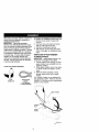
Loose Parts Packed Separately
20 OZ.
Bottle of oil
Trimmer Lines
(2) Sets
(0,155 diameter
x 15.75 inches long)
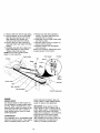
TO REMOVETRIMMER
FROM CARTON
1. Remove loose parts included with
trimmer.
2. Cut down two end corners of carton
and lay end panel down flat.
3. Remove all packing materials.
4. Roll trimmer out of carton and check
carton thoroughly for additional loose
parts.
HOWTO SET UPYOURTRIMMER
TO UNFOLD HANDLE
IMPORTANT: Unfold handle carefully so as
not to pinch or damage control cables.
1. Loosen handle knob enough to allow
upper handle to be unfolded from the
shipping position.
2. Raise upper handle section into place
on lower handle and tighten handle
knob.
3. Remove handle padding holding
trimmer head control bar to upper
handle.
Your trimmer handle can be adjusted for
your trimming comfort. Refer to "ADJUST
HANDLE" in the Service and Adjustments
section of this manual.
Upper handle
Lift up
knob
hendle
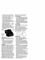
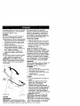
KNOW YOUR TRIMMER
READ THIS OWNER'S MANUAL AND SAFETY RULES BEFORE OPERATING YOUR
TRIMMER. Compare the illustrations with your tnmmer to familiarize yourself with the location
of various controls and adjustments. Save this manual for future reference,
symbolsmayappearonyourtrimmeror in literature
suppliedwiththe product.Leamandunderstand
CAUTION
ENGINE
FAST
SLOW
FUEL
OIL
OFF
met head control bar
head control lever
Starter handle
Engine oil cap
Gasoline
Chassis
IMPORTANT: This trimmer is shipped
WITHOUT OIL OR GASOLINE in the engine.
Trimmer head control bar - must be held
down to the handle to engage trimmer head.
Release to stop the trimmer head.
Primer - pumps additionalfuel from the
carburetorto the cylinderfor use when
starting a cold engine.
_Trimmer
line
Throttle control - used for starting and
stopping the engine and allows you to select
either fast or slow engine speed.
Starter handle - used for starting the engine.
Tdrnmer head control lever - used to
6 engage tnmmer head.
_
,Trimmer head control bar
\
Drive control
lever
SAFETYGLASSES
The operation of any trimmer can result in
foreign objects being thrown into the
eyes, which can result in severe eye
damage. Always wear safety glasses or
eye shields while operating your trimmer
or performing any adjustments or repairs.
We recommend a wide vision safety mask
over spectacles or standard safety
glasses.
HOWTO USEYOURTRIMMER
ENGINE SPEED
The engine speed is controlled by a
throttle located on the side of the upper
handle. Fast position is for starting and
normal trimming. Slow is for light trimming
and fuel economy. Stop is for stopping the
engine.
.,,,, 0
To engage trimmer head
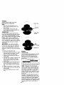
TO ADJUST TRIMMING HEIGHT
_,CAUTION:
Stop the engine and wait
for all moving parts to stop. Disconnect
spark plug wire from spark plug and
place wire where it cannot come in
contact with plug.
The height of cut can be set to six (6)
different positions ranging from 1-1/2
inches to 3 inches. Recommended cutting
height for the average yard is 2 inches.
1. To adjust trimming height, push in the
locking plate tab and move trimmer
head up or down to desired position.
2. Release tab and be sure head is
locked into one of the six (6) height
positions.
Adjustable
it
disengaged
_
Trimmer
Head
\
II
\
\
Locking
Plate Tab
J
TRIMMER HEAD DRIVE CONTROL
Your trimmer is equipped with a trimmer
head drive control bar and lever which
require the operator to be positioned
behind the trimmer handle to operate the
trimmer.
• Trimmer head rotation is controlled by
holding the trimmer head control bar
down to the handle and pushing the
drive control lever forward until it clicks;
then releasing the lever.
• Trimmer head rotation will stop when
the control bar is released.
\
BEFORE STARTING ENGINE
ADD OIL
Your trimmer is shipped without oil in the
engine. For type and grade of oil to use,
see "ENGINE" in the Maintenance section
of this manual.
• l, CAUTION: DO NOT overfill engine with
oil, or it will smoke on startup.
1. Be sure trimmer is level and area
around oil fill is clean.
2. Remove oil dipstick from oil fill spout,
Make sure that rim of spout is clean.
3. You receive a 20 oz. container of oil
with the unit. Slowly pour 3/4 (15 oz.)
of the oil from the container down the
6il fill spout into the engine.
4. Wait one minute to allow oil to settle.
Insert and tighten dipstick, then
remove it to check oil level.
5. Continue adding small amounts of oil
and rechecking the dipstick until it
reads full. DO NOT overfill, or engine
will smoke on startup.
6. Always be sure to retighten oil dipstick
before starting engine.
• Check oil level before each use. Add oil if
needed. Fillto full line on dipstick.
• Change the oil after every 25 hours of
operation or each season. You may need
to change the oil more often under dusty,
dirty conditions.
Gasoline
oil cap
spilled oil or fuel. Do not store, spill or
use gasoline near an open flame.
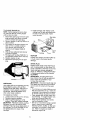
TO START ENGINE
1. To start a cold engine, push primer three
(3) times before trying to start. Use a firm
push. This step is not usually necessary
when starting an engine which has
already run for a few minutes.
2. Move throttle control lever to fast position.
3. Hold upper handle firmly and pull starter
handle quickly. Do not allow starter rope
to snap back.
TO STOP ENGINE
• To stop engine, move throttlecontrol lever
to stop position.
NOTE: In cooler weather it may be
necessary to repeat priming steps. In
warmer weather overpriming may cause
flooding and engine will not start. If you
do flood engine, wait a few minutes
before attempting to start and do not
repeat priming steps.
_
Throttle control _!'
(Discard
debris plug
inside)
Starter handle _
TRIMMINGTIPS
ADD GASOLINE
_/&
• Set the throttle control in the fast
NOTE; Before filling fuel tank, remove
position. If the weeds or grass are tall
and discard the debris plug that is inside
and thick, operate the trimmer at a
the tank.
slower walking speed.
• Fill fuel tank. Use fresh, clean, regular
• Frequently clean the underside of the
unleaded gasoline with a minimum of 87
trimmer to remove any grass build up.
octane. Do not mix oil with gasoline.
Keep top of engine around starter clear
Purchase fuel in quantities that can be
and clean of grass clippings and chaff.
used within 30 days to assure fuel
This will help engine air flow and extend
freshness.
engine life.
_I,WARNING: Experience indicates that
• For best results and longer lasting line,
alcohol blended fuels (called gasohol or
use the ends of the line to do the cutting.
using ethanol or methanol) can attract
This is easily done by moving slowly
moisture which leads to separation and
through very thick and heavy weeds.
formation of acids during storage. Acidic
• Use the left side of trimmer when
gas can damage the fuel system of an
trimming along fences, walls, flowerbeds
engine while in storage. To avoid engine
and other such objects.
problems, the fuel system should be
• If trimmer lines become too short, it will
emptied before storage of 30 days or
take longer to complete the job. If
longer. Drain the gas tank, start the
trimmer lines are worn to less than half
engine and let it run until the fuel lines
their original length, they should be
and carburetor are empty. Use fresh fuel
replaced. See "TO REPLACE TRIMMER
LINE" in the Maintenance section of this
next season. See Storage Instructions for
additional information.
Never use engine
manual.
or carburetor cleaner products in the fuel
Trimmer head contact with concrete,
tank or permanent damage may occur.
asphalt or other hard surfaces may
Ai_CAUTION; Fill to bottom of gas tank
cause premature wear of the ball on
bottom of trimmer head.
filler neck. Do not overfill. Wipe off any
8
MAINTENANCE
SCHEDULE
_'_, _"_//-
_,_ ,/_..
_O_/_G_/'"
REGUL RSE.V,CE
T
a
Check for Loose Fasteners
I_
Clean Trimmer
I/
I_
I/
I
M
Clean Under Engine Cover
M
Check ddve belt/pulleys
R
Check/Replace
11/2
II/
l/
Trimmer Lines
11/3
Check Engine Oil Level
I# #
E
Change Engine Oil
I/1,2
(_
Clean Air Filter
_
I
Inspect Muffler
it/
Clean or Replace Spark Plug
¥1
N
Replace Air Filter Paper Cartridge
1
Change
mote
often
2
Service
more
Often when
3.
AOplace
Irimmer
GENERAL
when
lines
operatin
operallng
when
9 under
1_2
a heaVy
in dirty
they have
2
worn
or dusty
load or in high ambient
ternpCralures.
cOflditions.
Io half their original
RECOMMENDATIONS
The warranty on this trimmer does not
cover items that have been subjected to
operator abuse or negligence. To receive
full value from the warranty, operator must
maintain trimmer as instructed in this
manual.
Some adjustments will need to be made
periodically to properly maintain your unit.
All adjustments in the Service and
Adjustments section of this manual should
be checked at least once each season.
• Once a year, replace the spark plug
and replace air filter element. A new
spark plug and clean/new air filter
element assures proper air-fuel
mixture and helps your engine run
better and last longer.
Follow the maintenance schedule in
this manual.
BEFORE EACH USE
1. Check engine oil level.
2. Check for loose fasteners.
3. Clean under engine cover.
LUBRICATION
To prolong the useful life of your trimmer,
change engine oil as recommended in
this section of Owner's Manual.
length¸
IMPORTANT: Do not oil or grease plastic
wheel bearings. Viscous lubricants will
attract dust and dirt that will shorten the
life of the self- lubricating bearings. If you
feel they must be lubricated, use only a
dry, powdered graphite type lubricant
sparingly.
PRODUCT
SPECIFICATIONS
Serial No.
Date of Purchase:
Gasoline Type:
Unleaded Regular
Gasoline Capacity:
1,25 Quarts
Oil Type:
SAE 30 (Above 32 ° F)
(API-SF-SJ)
SAE 5W-30 (Below 32° F)
Oil Capacity:
20 Ozs.
Spark Plug :
Champion J19LM
(Gap: .030")
or RJ19LM
Trimmer Line Dia,:
.155 inch
Trimmer
Line Length:
18.75 inches
The model and serial numbers will be
found on a decal attached to the rear of
the trimmer. Record both serial number
and date of purchase in space provided
above.
TRIMMER
Always observe safety rules when
performing any maintenance.
TIRES
Keep tires free of gasoline, oil, or
insect control chemicals which can
harm rubber.
• Avoid stumps, stones, deep ruts,
sharp objects and other hazards that
may cause tire damage.
TRIMMER LINE
For best results, replace trimmer lines
when they have worn to half their original
length. Use .155 inch diameter trimmer
line. Cut new trimmer line length to 18-314
inches. After new line is installed on
trimmer head, check all lines so they do
not vary more then one (1) inch in length.
This is important to make sure the trimmer
head is balanced and will not vibrate
abnormally.
_WARNING:
Use only the specified
trimmer line. Do not use other materials
such as wire, string, rope, etc. Wire can
break off during trimming and become a
dangerous missile that can cause serious
injury.
TO REPLACE TRIMMER
LINE
1. Disconnect spark plug wire from spark
plug and place wire where it cannot
come in contact with spark plug.
2. Remove worn trimmer line from line
carrier plate.
3. Fold new, cut to length, trimmer line in
half and insert folded end through
carrier plate opening to back side of
retainer clip.
4. With folded end of line at back side of
retainer clip, pull line outward until
line is fully seated under the retainer
clip.
5. Repeat on other side of carrier plate.
6. Check all lines to be sure they are the
same length.
7. Reconnect spark plug wire to spark
plug.
Trimmer line
Carrier plate
opening
ENGINE
LUBRICATION
Use only high quality detergent oil rated
with API service classification SF-SJ.
Select the oil's SAE viscosity grade
according to your expected operating
temperature.
[_
SA_V_SCOS,T_
GR_OES
*F
*C
20.
_0.
O,
.20,
30,
10.
32.
O*
4_*
60*
10.
1
t_O,
2O,
lc0,
t_.
E40*
NOTE: Although multi-viscosity oils
(5W30, 10W30 etc.) improve starting in
cold weather, these multi-viscosity oils
will result in increased oil consumption
when used above 32°E Check your
engine oil level more frequently to avoid
possible engine damage from running
low on oil.
Change the oil after every 25 hours of
operation or at least once a year if the
unit is not used for 25 hours in one year.
Check the crankcase oil level before
starting the engine and after each five (5)
hours of continuous use. Tighten oil plug
securely each time you check the oil
lolevel.
TO CHANGE ENGINE OiL
NOTE: Before tipping trimmer to drain
oil, drain fuel tank by running engine
until fuel tank is empty.
1. Disconnect spark plug wire from spark
plug and place wire where it cannot
come in contact with spark plug.
2. Remove engine oil cap; lay aside on a
clean
Slots
surface.
3. Tip trimmer on its side as shown and
drain oil into a suitable container.
Rock trimmer back and forth to
remove any oil trapped inside of
engine.
4. Wipe off any spilled oil from trimmer
and side of engine.
5. Fill engine with oil (See "ADD OIL" in
the Operation section of this manual).
6. Replace engine oil cap.
7. Reconnect spark plug wire to spark
plug.
Container
AIR FILTER
Your engine will not run properly and may
be damaged by using a dirty air filter.
Replace the air filter every 100 hours of
operation or every season, whichever
occurs first. Service a_ cleaner more
often under dusty conditions.
TO
1.
2.
3.
4. Install cartridge, then replace cover
making sure the tabs are aligned with
the slots in the back plate. Fasten
screw securely.
Back plate
CLEAN AIR FILTER
Loosen screw and tilt cover to remove.
Carefully remove cartridge.
Clean by gently tapping on a flat
surface. If very dirty, replace cartridge.
_,CAUTION:
Petroleum solvents, such as
kerosene, are not to be used to clean
cartridge. They may cause deterioration of
the cartridge. Do not oi_cartridge. Do not
use pressurized air to clean or dry
cartridge.
Cover
tabs
Cover
MUFFLER
Inspect and replace corroded muffler as
it could create a fire hazard and/or
damage.
SPARK PLUG
Replace spark plugs at the beginning of
each mowing season or after every 100
hours of operation, whichever occurs first.
Spark plug type and gap setting are
shown in "PRODUCT SPECIFICATIONS"
in Maintenance section of this manual.
CLEANING
IMPORTANT= For best performance,
keep tdmmer free of buitt-up grass and
trash. Clean the underside of your
trimmer after each use.
_CAUTION:
Disconnect spark plug wire
from spark plug and place wire where it
cannot come in contact with the spark
plug.
• Turn trimmer on its side, Make sure air
fi_ter and carburetor are up. Clean the
underside of your trimmer by scraping
to remove build-up of grass and trash.
• Clean engine often to keep trash from
accumulating.
A clogged engine runs
hotter and shortens engine life.
• Keep finished surfaces and wheels
free of all gasoline, oil,etc.
• We do not recommend using a garden
hose to clean trimmer unless the
electrical system, muffler, air filter and
carburetor are covered to keep water
out. Water in engine can result in
shortened engine life.
11
A CAUTION: Before performing any
service and adjustments:
1. Stop engine.
2. Make sure the rotating lines and all
moving parts have completely
stopped.
3. Disconnect spark plug wire from spark
plug and place where it cannot come
in contact with plug.
TO REMOVE/REPLACE TRIMMER HEAD
DRIVE BELT
1. Remove screw at front of chassis
cover.
2, Lift cover up and away from trimmer.
TRIMMER
TO ADJUSTTRIMMING HEIGHT
See 'q'O ADJUSTTRIMMING HEIGHT" in the
Operation section of this manual.
TO ADJUST
HANDLE
The upper handle may be adjusted to
different height positions.
• Loosen handle knob only enough to
allow the upper handle to pivot to the
desired position.
• Tighten handle knob securely.
NOTE: The handle knob and bolt may be
reversed for left handed operation,
Upper handle
Chassis
3. Remove the two (2) screws on sides
of trimmer securing the debris shield.
4. Turn trimmer on its side with carburetor and fuel cap up.
5. Remove the two (2) screws on
underside of trimmer securing the
debris shield.
6. Slide the debris shield rearward and
remove.
7. Remove belt from engine pulley on
crankshaft.
pulley
Debris shield screws
Handle knob
12
8. Remove belt from trimmer head pulley.
9. Note the position of the control cable
+and idler return spring, then remove
idler assembly from chassis and
remove belt and idler from trimmer.
10. Remove belt from idler assembly by
removing bottom belt keeper and idler
pulleys.
11.Assemble new belt, idler pulleys and
bottom belt keeper to idler bracket.
Tighten pulley bolts securely.
NOTE: Be sure belt is inside top belt
keeper on idler assembly.
12. Position belt and idler assembly in
trimmer, reconnect idler spring and
assemble idler to chassis.
13. Install belt around trimmer head pulley
and engine pulley.
14. Replace debris shield and tighten the
four (4) screws securely.
15. Replace chassis cover and tighten
screw securely.
Always use Craftsman replacement parts
to assure proper fit and long life.
Idler bracket
Flatidler
Spacer
V-idler._,
Idler
Flat idler
Beff
Trimmer head pulley
ENGINE
ENGINE SPEED
Your engine speed has been factory set.
Do not attempt to increase engine speed
or it may result in personal injury, If you
believe that the engine is running too fast
or too slow, take your unit to a Sears or
other qualified service center for repair
and/or adjustment.
CARBURETOR
Your carburetor has a nonadjustable fixed
main jet for mixture control. If your engine
does not operate properly due to sus-
pected carburetor problems, take your
unit to a Sears or other qualified service
center for repair and/or adjustment.
IMPORTANT: Never tamper with the
engine governor, which is factory set for
proper engine speed. Overspeeding the
engine above the factory high speed
setting can be dangerous. If you think the
engine-governed high speed needs
adjusting, take your unit to a Sears or
other qualified service center, which has
proper equipment and experience to
make any necessary adjustments.
13
Imrdediately prepare your trimmer for storage
at the end of the season or if the unit will not
be used for 30 days or more.
TRIMMER
When trimmer is to be stored for a pedod of
time, clean it thoroughly,remove all dirt,
grease, leaves, etc. Store in a clean, dry area.
1. Clean entire trimmer (See "CLEANING" in
the Maintenance section of this manual).
2. Lubricate as shown in the Maintenance
section of this manual.
3. Be sure that all nuts, bolts, screws, and
pins are securely fastened. Inspect
moving parts for damage, breakage and
wear. Replace if necessary.
4. Touch up all rusted or chipped paint
surfaces; sand lightly before painting.
HANDLE
You can fold your trimmer handle for storage.
• Loosen handle knob enough to allow
upper handle to be folded forward.
IMPORTANT: When folding the handle for
storage or transportation, be sure to fold the
handle as shown or you may damage the
control cables.
tank during storage. Also, experience
indicates that alcohol blended fuels (called
gasohol or using ethanol or methanol) can
attract moisture which leads to separation
and formation of acids during storage. Acidic
gas can damage the fuel system of an
engine while in storage.
1. Drain the fuel tank.
2. Start the engine and let it run until the
fuel lines and carburetor are empty.
• Never use engine or carburetor cleaner
products in the fuel tank or permanent
damage may occur.
• Use fresh fuel next season.
NOTE: Fuel stabilizer is an acceptable
aitemative in minimizing the formation of fuel
gum deposits during storage. Add stabilizer
to gasoline in fuel tank or storage container.
Paways follow the mix ratio found on stabilizer
container. Run engine at least 10 minutes
after adding stabilizer to allow the stabilizer to
reach the carburetor. Do not drain the gas
tank and carburetor if using fuel stabilizer.
ENGINEOIL
Drain oil (with engine warm) and replace with
clean engine oil. (See "ENGINE" in the
Maintenance section of this manual).
CYLINDER
t. Remove spark plug.
2. Pour one ounce (29 ml) of oil through
spark plug hole into cylinder.
3. Pull starter handle slowly a few times
to distribute oil.
4. Replace with new spark plug.
OTHER
• Do not store gasoline from one season to
another.
• Replace your gasoline can if your can
starts to rust. Rust and/or dirt in your
gasoline will cause problems.
• If possible, store your unit indoors and
cover it to give protection from dust and dirt.
• Cover your unit with a suitable protective
cover that does not retain moisture. Do
not use plastic. Plastic cannot breathe
which allows condensation to form and will
cause your unit to rust.
IMPORTANT: Never cover trimmer while
Handle knob
engine and exhaust areas are still warm.
ENGINE
_I, CAUTION: Never store the trimmer
FUEL SYSTEM
with gasoline in the tank inside a building
where fumes may reach an open flame or
IMPORTANT: if is importantto preventgum
depositsfrom forming in essentialfuel system
spark. Allow the engine to cool before
partssuch as carburetor, fuel filter,fuet hose or 14storing in any enclosure.
TROUBLESHOOTING
PROBLEM
6oesnotsta_
CAUSE
CORRECTION
1, Dirtyairfilter.
2. Out of fuel.
3, Stale fuel.
4. Water in fuel.
5. Spark plug wire is
disconnected.
6. Bad spark plug.
7. Throttle control lever not
in correct position
(if equipped).
1. Clean/replace air filter.
2. Fill fuel tank.
3. Drain tank and refill with
fresh clean fuel.
4. Drain fuel tank and
carburetor and refill tank
with fresh gasoline.
5. Connect wire to plug.
6. Replace spark plug.
7. Move throttle lever to FAST
position.
Loss of power
1. Dirty air filter.
2. Buildup of grass, leaves,
and trash under trimmer.
3. Too much oil in engine.
4. Walking speed too fast.
1. Clean/replace air filter.
2. Clean underside of trimmer
and trimmer head.
3. Check oil level.
4. Trim at slower walking
speed.
Excessive
Vibration
1. Lines uneven or broken.
2. Loose nuts or bolts.
1. Check trimmer lines.
2. Check all hardware,
including engine bolts.
3. Check/repair trimmer head.
3. Damaged
trimmer head.
Starter rope harc
to pull
1. Bent engine crankshaft.
1. Contact a Sears or other
qualified service center.
Loss of head
drive
1. Belt not driving.
1. Put belt on pulleys or
replace belt if broken.
Hard to push
1. Handle height position no1
right for you.
1. Adjust handle height
to suit.
Poor trimming
performance
1. Trimmer line length is
too short.
1. If line is worn or broken to
half original length,
replace line.
2. Move throttle lever to FAST
position.
2. Throttle control lever not
in correct position
(if equipped).
Trimmer head
does not
retain line
1. Trimmer line not
properly installed.
2. Broken line retainer clip.
3. Incorrect size of
trimmer line.
15
1. Follow instructions in
Maintenance section.
2. Replace string carrier plate
assembly.
3. Use .155 diameter
trimmer line.
SLOPE GUIDE
SIGHT AND HOLD THIS GUIDE LEVEL WITH A VERTICAL
TREE, A CORNER OF A STRUCTURE, A POWER LI'NE
"'°'_°*°'o,.°
I
.
-..
.
POLE, OR A FENCE.
o
Operate a trimmer across the face
of slopes, never up or down slopes.
15 DEGREES
Use this guide and do not trim on a slope greater than 15 degrees.
A 10 degree slope is a hill that increases
A 15 degree slope is a hill that increases
in height at approximately
in height at approximately
1.7 feet in 10 feet..
2.5 feet in 10 feet..
Use extreme care at all times and avoid sudden turns or maneuvers.
_lb
Follow other instructions
in this
an ual for safety in trimming on slopes. Operate a trimmer across the face of slopes, never up o r down
slopes. Use extra care when operating on or near slopes and obstructions.
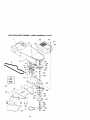
CRAFTSMAN
WEEDTRIMMER
- - MODEL
NUMBER 917.773700
29
28
21
26
14 15
8
9_
26
27
'_"
23
24
25
32
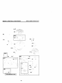
CRAFTSMAN WEED TRIMMER -- MODEL NUMBER 917.773700
KEY
NO.
PART
NO.
.....
2
3
4
8
9
10
11
12
13
14
15
16
17
18
19
20
21
22
23
24
25
26
27
28
29
30
31
32
33
150406
169791
STD502502
169821X479
150078
169797X479
170980
136376
170681
170682
170554
153638
STD541025
66486
171449
177814
158755
174750X004
150078
174751
57143
752063
83923
174037
178364
751152
111190X
83816
178365
177739
Available accessories
7133623
7133000
7!_79991
NOTE:
DESCRIPTION
Engine, Briggs & Stratton,
Model N umber 122H02-0110-D1
(See Breakdown)
Bolt, Engine Mounting 3/8-16
Pulley, Engine (Includes Setscrew, Key #4)
Setscrew, Pulley
Handle,Lower
Screw, Hex Washer Head 5/16-18 x .75
Handle, Upper
Bolt, Handle
Knob,Handle
Adjuster, Handle, Inside
Adjuster, Handle, Outside
Spring, Handle Adjust
Guide, Rope
Locknut 1/4 x 20
WireTire
Control Bar
Throttle Contro4
Screw, Hex Washer Head
Axle Shaft Assembly
Screw, Hex Washer Head 5/15-18 x .75
Spacer, Axle
Washer, Wave
Wheel, 14 x 2
Hex Flange Locknut 3/8-16
Orive Control
Decal,Warning
Nut 1/4-20
Clamp,Cable
Screw
Decal,Warning
Owner's Man ual. English/Spanish
not included with trimmer:
Gas Can (2.5 gal.)
SAE 30W Oil (20 oz.)
Trimmer Line (Pack of 24 strings, 155 dia,)
All component dimensions
1 inch = 25.4 mm
33
given in U.S, inches
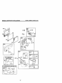
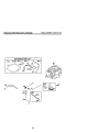
CRAFTSMAN WEED TRIMMER - - MODEL NU MBER 917.773700
1
_
20
42
14
21
-44
43
4
23
24
0--31
27
32
34
CRAFTSMAN
WEEDTRIMMER
- - MODELNUMBER917.773700
KEY
NO.
PART
NO.
1
2
3
4
5
6
7
8
9
10
11
12
13
14
15
16
17
18
19
2O
21
22
23
24
25
26
27
28
29
3O
174031 X558
169802
173715
169790
172145X004
166042
173716
751592
166043
160829
155552
173717
174719
145212
173811
177871
57808
85768
175301
170553
149746
STD541137
STD551137
STD551037
169792
172551
174549
172520
169766
174543
31
32
33
34
35
36
37
38
39
40
174581
176973
172519
174544
52784
172516
174590
172523
172636
172342
41
42
43
44
45
46
47
48
174029
174036
174042
174035
174596
17060408
76399
59931
NOTE:
DESCRIPTION
Chassis Assembly
Line, Trimmer .155 diameter x 18,75 long
Screw, Self-Tapping
5/16-18 x 1
V-Beg
Bracket, Idler
Pulley, Idler, V-Groove
Bolt, Hex Head 3/6-16 x 1.25
Locknut, Hex 3/8-16
Pulley. Idler, Flat
Bolt, Shoulder
Locknut 5/16-18
Spacer
Bolt, Shoulder
Locknut, Flange
Spring, Return
Shield, Debris
Screw 1/4-20 x 1/2
Screw #16-24 x 3/4
Skirt
Cover, Chassis, Top
Screw #10-24 x 1-3/4
Nut 3/8-24 UNF
Washer, Lock 3/8
Washer, Flat 3/8
Pulley, Driven
Spacer, Pulley
Beadng
Jackshaft
Cover, Chassis, Bottom
Spindle Housing Assembly
(" Includes Upper Bearing, Key #27)
Ring, Retaining, External, 17mm
Spring, Locking Plate
Locking Plate
Carrie r Plate Assembly
Washer
Cover, Beadng
Ring, Retaining, Internal, 40mm
Mow Ball
Bolt, Mow Ball
Head Assembly, Complete
(Includes Key Numbers 22-29, 30-39)
Spacer
Decal, Instruction
Decal, Instruction
Decal, Chassis Cover
Belt Keeper, Bottom
Screw
Screw
Nut
All component dimensions given in U.S. inches
1 Inch = 25.4 mm
35
BRIGGS & STRATTON
MODEL NUMBER 122HO2-O110-D1
4-CYCLE ENGINE
36
BRIGGS & STRATTON
4-CYCLE ENGINE
MODEL
NUMBER
122H02-0110-D1
fJ
lee_
968
621
f_J
/
445
12___J
977 CARBURETOR
GASKET SET
365_
_37_
137_
_
633 G
276
61 7_j
121 CARBURETOR
633_
OVERHAUL
I
KIT
163
27eQ 127_
37
617_il._l
27eo
MODEL NUMBER 122HO2-O110-D1
BRIGGS & STRA'FTON 4-CYCLE ENGINE
949
6O4
564
363 ,_i, i j
:I
"
78¸
332 _, _'
, i
304
,i'
1229
.
i'i
455 _ .r
L
!_
"
ii;I
23
305
670
190 ""
65 _i
057ITs,
592 _
58
55
_
_
_
r_'_
r
F
-
__
=
I
1211
459 '
_l
689
60 _
1210
187
i,,
_601
i
[ 1036 EMISSIONS
597.,
LABEL
]
38
BRIGGS & STRATTON 4-CYCLE ENGINE
MODEL
NUMBER
122H02-0110-D1
358 ENGINE GASKET SET
3©
20_
842_)
524_,
7_
80
585_
5
9
"
617_
334_
615
404 _
227
39
MODEL NUMBER 122H02-0110-D1
BRIGGS & STRATTON 4-CYCLE ENGINE
KEY
NO,
PART
NO.
1
2
3
4
5
7
8
9
10
11
12
13
15
16
20
22
23
24
25
493260
399269
299819
493279
691160
692249
695250
272481
691125
691781
692232
690912
691680
691451
399781
691092
692315
222698
499429
499430
499431
499432
499425
499426
499427
499428
691866
499423
499424
691664
695759
262651
262652
691270
691270
694086
692194
691997
690548
691449
26
27
28
29
32
32A
33
34
35
36
37
40
43
45
46
DESCRIPTION
Cylinder Assembly
KS-BushingJSeal
• Seal-Oil (Magneto Side)
Sump-Engtne
Head-Cylinder
,+ Gasket-Cylinder Head
Breather Assembly
-+ Gasket-Breather
Screw (Breather Assembly)
Tube-Breather
• Gasket-Crankcase
Screw (Cylinder Head)
Plug-Oil Drain
Crankshaft
• SeaI-Oil(PTO Side)
Screw (Engine Sump)
Flywheel
Key-Flywheel
Piston Assembly (Standard)
Piston Assembly (.010" O.S.)
Piston Assembly (.020' O.S.)
Piston Assembly (,030' O.S.)
Ring Set-Piston (Standard)
Ring Set-Piston (.010" O,S.)
Ring Set-Piston (.020"O.S.)
Ring Set-Piston (.030" O.S.)
Lock-Piston Pin
Pin-Piston
Rod-Connecting
Screw (Connecting Rod)
Screw (Connecting ROd)
Valve-Exhaust
Valve-intake
Spring-Valve (Intake)
Spring-Valve (Exhaust)
Guard-Rywheel
Retainer-Valve
Slinger-Governor/Oil
Tappet-Valve
Camshaft
KEY
NO.
PART
NO.
48
498826
50
51
54
55
58
60
65
78
81
95
97
104
117
497465
272199
691650
691421
692259
281434
690837
691108
691740
691636
493267
691242
494870
497315
498260
694468
691203
398187
398188
693981
690979
691753
272653
691050
690877
690940
691829
690319
692031
690783
690798
271716
690940
692038
696307
691108
690450
690345
121
127
130
133
134
137
146
159
163
187
188
190
202
209
222
227
265
276
287
300
304
305
306
307
4O
DESCRIPTION
Short Brock (Replacement
Engine 12D602-0015-B1 )
Manifold-Intake
• Gasket-Intake
Screw (Intake Manifold)
Housing-Rewind Starter
Rope-Starter (Cut to Length)
Grip-Starter Rope
Screw (Rewind Starter)
Screw (Flywheel Guard)
Lock-M uffier Screw
Screw (Throttle Valve)
Shaft-Throhle
O Pin-Float Hinge
Jet-Main (Standard)
Jet-Main (High Altitude)
Kit-Carburetor Overhaul
Q Plug-Welch
Valve-ThroSle
Float-Carburetor
_ Valve-Needle/Seat
O:_ Gasket-Float Bowl
Key-Timing
Bracket-Air Cleaner Prime r
_
Gasket-AirCleaner
Line- Fuel (Cut to Length)
Screw (Control Bracket)
Screw (Fuel Tank)
Link- Mechanical Governor
Spring-Governor
Bracket-Control
Control Lever-Governor
Clamp-Casing
:_ Sealing Washer
Screw (Dipstick Tube)
Muffler
Housing-Blower
Screw (Blower Housing)
Shield-Cylinder
Screw (Cylinder Shield)
BRIGGS & STRATTON
4-CYCLE ENGINE
KEY
NO,
PART
NO.
DESCRIPTION
332
333
334
337
356
358
363
365
383
404
425
443
445
455
456
459
505
523
524
525
529
562
563
564
584
585
592
597
601
604
608
613
615
616
617
621
633
635
668
670
6906o62
802574
691061
802592
692390
497316
19069
692524
89838
6911272
690670
692523
491588
691219
692299
281508
231082
495264
692296
495265
691923
92613
691138
690664
692342
691879
690800
691696
95162
691757
497680
691340
890340
691306
270344
692316
691321
66538
493823
692294
Nut (Flywheel)
Armature-Magneto
Screw (Armature Magneto)
Spark Plug
Wire-Stop
Engine Gasket Set
Flywheel Puller
Screw (Carburetor)
Wrench-Spark Plug
Washer (Governor Crank)
Screw (Air Cleaner Cover)
Screw (Air Cleaner Primer Base)
Fiber-Air Cleaner Cartridge
Cup-Flywheel
Plato-Pawl Friction
PawI-Ratchet
Nut (Governor Control Lever)
Dipstick
SeaI-DipstickTube
Tube-Dipstick
Grommet
Bolt (Governor Control Leve
Screw (Debris Guard Cover
Screw (Control Cover)
Cover-Breather Passage
Gasket-Breather
Passage
Nut (Rewind Starter)
Screw (Pawl Friction Plate
Clamp-Hose
Cover-Control
Starter-Rewind
Screw (Muffler)
Retainer-Governor Shaft
Crank-Governor
SeaI-O Ring(IntakeManifold)
Switch-Stop
SeaI-Choke/ThroSle Shaft
Boot-Sparkp_ug
Spacer (Includes 2)
Spacer-Fuel Tank
•
•
K_:_
•
MODEL
KEY
NO.
PART
NO.
684
690345
689
703
741
842
847
851
869
870
871
949
949A
957
966
967
968
970
691855
696309
691830
691031
692017
493880
691155
690380
262001
63709
696306
696310
397974
496118
493537
692298
691669
972
975
976
977
1019
1036
1058
1059
1095
1210
1211
1229
495224
493640
694395
498261
494256
696035
274978
692311
498528
498144
498144
696308
•
O
_t
+
122HO2-O110-D1
DESCRIPTION
Scre
(Breather Passage Cover)
Spdng*Fdction
Clip
Gear-]]ming
° SeaI-O Ring (Dipstick Tube)
A ssem bly- DipslJckJTu b e
TerminaI-Sparkplug
Seat-Valve (Intake)
Seat-Valve (Exhaust)
Bushing-Guide(Exhaust)
Bushing-Guide (Intake)
Guard-Debris Screen
Guard-Debris Screen
Cap-FuelTank
Base-AirCleanerPdmer
Filter-Pre Cleaner
Cover-Air Cleaner
Screw
(Air Cleaner Primer Bracket)
Tank-Fuel
Bowl-Float
Pdmer-Carburetor
Set-Carburetor Gasket
Kit-Label
Label-Emissions
Owner's Manual
Kit-Screw/Washer
Set-Valve Gasket
Assembly-Pulley/Spring(Pulley)
Assembly-Pulley/Spnng
(Spdng)
Extension-Blower Housing
Included in Engine Gasket Set, Key #358
Included in Carburetor Overhaul Kit, Key #121
Included in Carburetor Gasket Set, Key #977
Included in Valve Overhaul Kit, Key #1095
NOTE:
41
NUMBER
All component dimensions
1 inch = 25.4 mm
given in U.S. inches
Get it fixed, at your home or ours!
For repair of major brand appliances in your own home...
no matter who made it, no matter who sold it!
1-800"4"MY-HOM
E sM Anytime, dayor
night
(1-800-469-4663)
www,sears.com
To bring in products such as vacuums,
lawn equipment and electronics for repair, call for
the location of your nearest Sears Parts & Repair Center.
1-800-488-1222
Anytime, day or night
www,sears.com
For the replacement parts, accessories and owner's manuals
that you need to do-it-yourself, call Sears PartsDirectSM!
1-800-366"PART
(1-800-366-7278)
_am- 11p,m,
CST,
7 days a week
www, sears.com/pa r tsdirect
To purchase or inquire about a Sears Service Agreement:
1-800-827-6655
7 a.m.- 5 p.m.CST,Mon.- Sat.
Para pedir servicio de reparaciSn a domici]io,
y para ordenar piezas con entrega a domicilio:
1-888-SU-HOGAR
(1-888-784-6427)
SM
{°°,°°
]
HomeCentral
© Seam,
177739
Roebuck
_
Regis,v.l_ I TMM=rt'_ dA r-._nA dA Rnam R_ebuck aTidCo
and Co
01.16.01
Au Canada pour service en franqais:
1-877-LE-FOYER
s_
(1-877-533-6937)
BY
Printed in U.S.A.