1
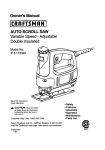
Operator's Manual
ROUTER
Double Insulated
Model No.
315.175341
Save this manual for future reference
_,
CAUTION: Read and follow all safety
rules and operating instructions before
first use of this product.
Customer
Help Line: 1-800-932-3188
Sears,
Roebuck
and Co., 3333 Beverly
Rd., Hoffman
Visit the Craftsman
Web page: www.sears.com/craftsman
983000-435
6-04
Estates,
IL 60179
USA
•
Warranty ................................................................................................................................................................
2
•
General Safety Rules ............................................................................................................................................
3
•
Specific Safety Rules .............................................................................................................................................
4
•
Symbols ..............................................................................................................................................................
•
Electdcal ................................................................................................................................................................
7
•
Features ................................................................................................................................................................
8
•
Unpacking ..............................................................................................................................................................
9
•
Operation ........................................................................................................................................................
•
Maintenance ........................................................................................................................................................
19
•
Accessodes .........................................................................................................................................................
20
•
Exploded View and Repair Parts List .............................................................................................................
•
Customer Service Information .............................................................................................................................
5-6
10-18
22-23
24
FULL ONE YEAR WARRANTY ON CRRFT$1vlRH ROUTER
If this CRRFTSHRN tool fails to give complete satisfaction within one year from the date of purchase, return it to
the nearest Sears store in the United States, and Sears will repair it, free of charge.
If this CRRFT$14RN tool is used for commercial or rental purposes, this warranty applies for only 90 days from the
date of purchase.
This warranty gives you specific legal rights,and you may also have other dghts which vary from state to state.
Sears, Roebuck and Co., Dept. 817 WA, Hoffman Estates, IL 60179
2
_.
WARNING: Read and understand all instructions. Failureto follow all instructionslisted below, may resultin electric shock,fire and/or serious personal injury.
SAVE THESE INSTRUCTIONS
WORK AREA
•
Keep your work area clean and well lit. Cluttered
benches and dark areas invite accidents.
• Do not operate power tools in explosive atmospheres, such as in the presence of flammable
liquids, gases, or dust. Power tools create sparks
which may ignitethe dust or fumes.
• Keep bystanders, children, and visitors away
while operating a power tool. Distractionscan
cause you to lose control.
ELECTRICAL SAFETY
•
Double insulated tools are equipped with a
polarized plug (one blade Is wider than the
other). This plug will fit in a polarized outlet only
one way. If the plug does not fit fully in the outlet,
reverse the plug. If it still does not fit, contact a
qualified electrician to install a polarized outlet.
Do not change the plug in any way. Double insulation [] eliminates the need for the three-wire
grounded power cord and grounded power supply
system.
• Avoid body contact with grounded surfaces such
as pipes, radiators, ranges, and refrigerators.
There is an increased risk of electric shock if your
body is grounded.
• Don't expose power tools to rain or wet conditions. Water entering a powertool will increase the
risk of electric shock.
• Do not abuse the cord. Never use the cord to
carry the tools or pull the plug from an outlet.
Keep cord away from heat, oil, sharp edges, or
moving parts. Replace damaged cords immediately. Damaged cords increase the risk of electric
shock.
• When operating a power tool outside, use an
outdoor extension cord marked "W-A" or "W".
These cords are rated for outdooruse and reduce the
risk of electric shock.
PERSONAL SAFETY
•
•
•
Stay alert, watch what you are doing and use
common sense when operating a power tool. Do
not use tool while tired or under the influence of
drugs, alcohol, or medication. A moment of
inattention while operating power tools may result in
serious personal injury.
Dress properly. Do not wear loose clothing or
jewelry. Contain long hair. Keep your hair, clothing, and gloves away from moving parts. Loose
clothes, jewelry, or long hair can be caught in moving
parts.
Avoid accidental starting. Be sure switch is off
before plugging in. Carrying tools with your finger
on the switchor plugging in tools that have the switch
on invites accidents.
• Remove adjusting keys or wrenches before
turning the tool on. A wrench or a key that is left
attached to a rotatingpart of the tool may resultin
personalinjury.
• Do not overreach. Keep proper footing and
balance at all times. Proper footingand balance
enables better control of the tool in unexpected
situations.
• Use safety equipment. Always wear eye protection. Dust mask, nonskid safety shoes, hard hat, or
hearing protection must be used for appropriate
conditions.
• Do not wear loose clothing or jewelry. Contain
long hair. Loose clothes, jewelry, or long hair can be
drawn intoair vents.
• Do not use on a ladder or unstable support.
Stable footingon a solid surface enables better
controlof the tool in unexpected situations.
TOOL USE AND CARE
•
•
•
•
•
•
•
•
•
Use clamps or other practical way to secure and
support the workpiece to a stable platform.
Holding the work by hand or against your body is
unstable and may lead to loss of control
Do not force tool. Use the correct tool for your
application. The correcttool will do the job better
and safer at the rate for which it is designed.
Do not use tool if switch does not turn it on or
off. Any tool that cannot be controlledwith the switch
is dangerous and must be repaired.
Disconnect the plug from power source before
making any adjustments, changing accessories,
or storing the tool. Such preventivesafety measures reduce the risk of starting the tool accidentally.
Store idle tools out of the reach of children and
other untrained persons. Tools are dangerousin
the hands of untrained users.
Maintain tools with care. Keep cutting tools
sharp and clean. Properly maintained toolswith
sharp cutting edges are less likely to bind and are
easier to control.
Check for misalignment or binding of moving
parts, breakage of parts, and any other condition
that may affect the tool's operation. If damaged,
have the tool serviced before using. Many accidents are caused by poorlymaintained tools.
Use only accessories that are recommended by
the manufacturer for your model. Accessoriesthat
may be suitable for one tool, may become hazardous
when used on another tool.
Keep the tool and its handle dry, clean and free
from oil and grease. Always use a clean clothwhen
cleaning. Never use brake fluids,gasoline, petroleumbased products,or any strong solvents to clean your
tool. Following this rule will reduce the risk of loss of
control and deterioration of the enclosure plastic.
• When servicing a tool, use only identical replacement parts. Follow instructions in the Maintenance section of this manual. Use of unauthorized
parts or failure to follow Maintenance Instructions
may create a risk of electric shock or injury.
SERVICE
• Tool service must be performed only by qualified
repair personnel. Service or maintenance performed
by unqualified personnelcould result in a riskof
injury.
•
Hold tool by insulated gripping surfaces when
performing an operation where the cutting tool
may contact hidden wiring or its cord. Contact
with a "live" wire witl make exposed metal parts of
the tool "live" and shock the operator.
ADDITIONAL SAFETY RULES
•
•
•
•
•
•
•
Know your power tool. Read operator's manual
carefully. Learn its applications and limitations,
as well as the specific potential hazards related
to this toot. Followingthis rule will reduce the risk of
electric shock,fire, or serious injury.
Always wear safety glasses. Everyday eyeglasses
have only impact-resistant lenses; they are NOT
safety glasses. Following this rule will reduce the
risk of serious personal injury.
Protect your lungs. Wear a face or dust mask if
the operation is dusty. Followingthis rule will
reduce the risk of serious personal injury.
Protect your hearing.Wear hearing protection
during extended periods of operation. Following
this rule will reduce the risk of serious personal injury.
Inspect tool cords periodically and, if damaged,
have repaired at your nearest Authorized Service
Center. Constantly stay aware of cord location.
Followingthis rule will reduce the risk of electric
shock or fire.
Never attempt to use the router motor without
first installing it in the fixed base (Model No.
315.175310), D-handle base (Mode] No.
315.175300), or plunge base (Model No.
315.175320).
Check damaged parts. Before further use of the
tool, a guard or other part that is damaged
should be carefully checked to determine that it
will operate properly and perform its intended
_L
•
•
•
•
•
function. Check for alignment of moving parts,
binding of moving parts, breakage of parts,
mounting, and any other conditions that may
affect its operation. A guard or other part that is
damaged should be properly repaired or replaced
by an authorized service center. Following this rule
will reduce the risk of shock,fire, or serious injury.
Do not abuse cord. Never carry the tool by the
cord or yank it to disconnect it from the receptacle. Keep cord away from heat, oil, and sharp
edges. Following this rule will reduce the risk of
electricshock or fire.
Make sure your extension cord is in good condition. When using an extension cord, be sure to
use one heavy enough to carry the current your
product will draw. A wire gage size (A.W.G.) of at
least 14 is recommended for an extension cord 50
feet or less in length. A cord exceeding 100 feet is
not recommended. If in doubt, use the next
heavier gage. The smaller the gage number, the
heavier the cord. An undersizedcord willcause a
drop in line voltage resulting in loss of power and
overheating.
Inspect for and remove all nails from lumber
before using this tool. Followingthis rule will reduce
the risk of serious personal injury.
Drugs, alcohol, medication. Do not operate tool
while under the influence of drugs, alcohol, or
any medication. Followingthis rule will reduce the
risk of electricshock, fire, or serious personalinjury.
Save these instructions. Refer to them frequently
and use them to instruct others who may use this tool.
If you loan someone this tool, loan them these
instructionsalso.
WARNING: Some dust created by power sanding, sawing, grinding,drilling, and other construction activities
contains chemicals known to cause cancer, birth defects or other reproductive harm. Some examples of these
chemicals are:
• lead from lead-based paints,
• crystalline silica from bricks and cement and other masonry products, and
• arsenic and chromium from chemically-treated lumber.
Your risk from these exposures varies, depending on how often you do this type of work. To reduce your
exposure to these chemicals: work in a well ventilated area, and work with approved safety equipment, such
as those dust masks that are specially designed to filter out microscopic particles.
4
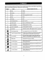
Some of the following symbols may be used on this tool. Please study them and learn their meaning. Proper interpretation of these symbols will allow you to operate the tool better and safer.
SYMBOL
NAME
DESIGNATION/EXPLANATION
V
Volts
Voltage
A
Amperes
Current
Hz
Hertz
Frequency (cycles per second)
W
Watt
Power
Minutes
Time
Alternating Current
Type of current
Direct Current
Type or a characteristic of current
no
No Load Speed
Rotational speed, at no load
[]
Class II Construction
Double-insulated construction
Per Minute
Revolutions, strokes, surface speed, orbits etc., per minute
Wet Conditions Alert
Do not expose to rain or use in damp locations.
min
"L,
---:-
.../min
Read The Operator's Manual
O
_{_
stand
the operator's
before
To
reduce
the risk of manual
injury, the
userusing
must this
readproduct.
and under
Eye Protection
shields
full face
shield or
when
operating
Always and
wearasafety
goggles
safety
glassesthis
withproduct.
side
Safety Alert
Precautions that involve your safety.
No Hands Symbol
serious
personal
injury.
Failure to
keep your
hands away from the blade will result in
No Hands Symbol
serious
personal
injury.
Failure to
keep your
hands away from the blade will result in
No Hands Symbol
serious
personal
injury.
Failure to
keep your
hands away from the blade will result in
No Hands Symbol
serious
personal
injury.
Failure to
keep your
hands away from the blade will result in
The followingsignalwordsand meaningsare intendedto explainthe levelsof risk associatedwith
this product.
SYMBOL
MEANING
DANGER:
Indicates an imminently hazardous situation, which, if not avoided, will
result in death or serious injury.
WARNING:
Indicates a potentially hazardous situation, which, if not avoided, could
result in death or serious injury.
CAUTION:
Indicates a potentially hazardous situation, which, if not avoided, may result in minor or moderate injury.
(Without Safety Alert Symbol) Indicates a situation that may result in property damage.
SERVICE
,_
Servicing requires extreme care and knowledge and should
be performed only by a qualified service technician. For
service we suggest you return the product to your nearest
AUTHORIZED SERVICE CENTER for repair. When
servicing, use only identical replacement parts.
WARNING: To avoid serious personal injury, do
not attempt to use this product until you read
thoroughly and understand completely the
operator's manual Save this operator's manual
and review frequently for continuing safe operation
and instructing others who may use this product.
_,
WARNING: Observe all normal safety
precautions related to avoiding electrical shock.
_,
WARNING:
The operation of any tool can result in foreign objects being thrown into your eyes, which can result in
O
side shields and a full face shield when needed. We recommend Wide Vision Safety Mask for use
severe eye damage. Before beginning operation, always wear safety goggles or safety glasses with
over eyeglasses or standard safety glasses with side shields. Always wear eye protection which is
marked to comply with ANSI Z87.1.
SAVE THESE INSTRUCTIONS
6
DOUBLE
EXTENSION
INSULATION
Double insulationis a concept in safety in electric power
tools, which eliminates the need for the usual three-wire
grounded power cord. All exposed metal parts are
isolated from the internal metal motor components with
protecting insulation. Double insulated tools do not need
to be grounded.
_i
When using a power tool at a considerable distance
from a power source, be sure to use an extension cord
that has the capacity to handle the current the tool will
draw. An undersized cord will cause a drop in line
voltage, resulting in overheating and loss of power. Use
the chart to determine the minimum wire size required
in an extension cord. Only round jacketed cords listed
by Underwriter's Laboratories (UL) should be used.
WARNING" The double insulated system is
intended to protect the user from shock resulting
from a break in the tool's internal wiring. Observe
all normal safety precautions to avoid electrical
shock.
When working outdoors with a tool, use an extension
cord that is designed for outside use. This type of cord
is designated with "_MA"on the cord's jacket.
Before using any extension cord, inspect it for loose or
exposed wires and cut or worn insulation.
Important: Servicing of a tool with double insulation
requires extreme care and knowledge of the system and
should be performed only by a qualified service
technician. For service, we suggest you return the tool
to your nearest authorized service center for repair.
When servicing, use only identical Craftsman
replacement parts.
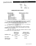
ELECTRICAL
CORDS
"*Ampere rating (_
tool faceplate)
02,0
2.1-3.4
Cord Length
CONNECTION
The router has a precision built electric motor. It should
be connected to a power supply that is 120 volts, 60
Hz, AC only (normal household current). Do not
operate this tool on direct current (DC). A substantial
voltage drop will cause a loss of power and the motor
will overheat. If your tool does not operate when
plugged into an outlet, double-check the power supply.
3.5-5.0
51-7.0
71-12.0
12.1-16.0
Wire Size (A.W.G.)
25'
16
16
16
16
14
14
50'
16
16
16
14
14
12
100'
!6
16
14
12
10
--
**Used on 12 gauge - 20 amp circuit.
7
A
CAUTION: Keep the extension cords clear of the
working area. Position the cord so that it will not
get caught on lumber, tools, or other obstructions
while you are working with a power tool. Failure to
do so can result in serious personal injury.
A
WARNING: Check extension cords before each
use. if damaged replace immediately.Never use
tool with a damaged cord since touching the
damaged area could cause electrical shock
resulting in serious injury.
PRODUCT
SPECIFICATIONS
Depth of Cut (Fixed Base & D-handle Base) .............................................................................................
1-1/2 in.
Depth of Plunge (Plunge Base) .........................................................................................................................
Collet ..............................................................................................................................................................
Horsepower ............................................................................................................................................................
Rating .......................................................................................................
2 in.
1/4 in.
2
120 Volts, 60 Hz, AC only, 9.5 Amperes
No Load Speed ......................................................................................................................................
25,000/min
Power Cord .....................................................................................................................................................
Net Weight .............................................................................................................................................
10 ft.
5 Ibs. 6 oz.
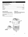
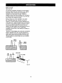
KNOW YOUR ROUTER
SPINDLE LOCK
Before attempting to use this product, familiarize
youmelf with all operating features and safety rules.
The spindle lock secures the spindlewhile you make
adjustments and acts as a retainer to keep the router
body from coming out of the base.
Your new router motor is equipped with the following
features. See Figure 1.
SWITCH
The router has a conveniently located toggle switch.
SWITCH
MOTOR_
HOUSING_
GOLDSPINDLE
LOCKBUTTON
Fig. 1
8
INSTRUCTIONS
•
PACKING
LIST
Router Motor
Carefully remove the tool and the accessoriesfrom
the box.
Wrench
•
Make sure that all items listed in the packing list are
included.
Operator's Manual
•
Inspect the tool carefully to be sure no breakage or
damage occurred during shipping.
_
•
Do not discard the packing material until you have
carefully inspected and satisfactorily operated the
tool.
WARNING: If any parts are missing, do not
operate your tool untilthe missing parts are
replaced. Failure to do so could result in serious
personal injury.
•
If any parts are damaged or missing, please catl
1-800-932-3188 for assistance.
_
WARNING: The router should never be connected
to a power supply when you are assembling parts,
making adjustments,cleaning, performing
maintenance, or when the tool is not in use.
Disconnectingthe tool preventsaccidental starting
that could cause serious injury.
9
_,
WARNING: Never connect the router to power
supply when you are assembling parts, making
adjustments, installing or removing cutters, or
when not in use. Disconnecting the router prevents
accidental starting that could cause serious injury.
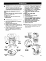
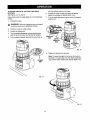
REMOVING AND INSTALLING
BASE
THE ROUTER
TO SWITCH FROM THE FIXED BASE OR D-HANDLE
BASE TO THE PLUNGE BASE
See Figures 2 and 3.
TO REMOVE THE FIXED OR D-HANDLE BASE:
1. Unplug the router,
,_
WARNING: Failure to unplugthe tool could result
in accidental starting causingserious.
2.
Place the router upside down with the Craftsman
label away from you.
3.
Loosen the locking arm on the base.
4.
Depress and hold the gold spindle lock button. The
gold spindle lock button will not depress fully unless
it is in line with the hole in the collet.
5.
6. Turn the depth adjusting ring counterclockwise until
the motor is to its highest position. NOTE: As the
motor is rising, the gold spindle lock button has to
be depressed until it clears the rear window.
7.
Align the indicator arrow on the depth adjustment
ring with the indicator point on the base.
8.
Pull the base until it dislodges from the motor
housing.
TO INSTALL THE PLUNGE BASE
1.
2.
Unplug the router.
Place the plunge base on a flat surface.
3.
Loosen the locking knob.
4.
Align the groove in the motor housing with the rib
inside the base. NOTE: The rib is located on the
inside of the base in line with the handle.
5.
6.
Depress and hold the gold spindle lock button.
Slide the motor housing into the base.
7. Tighten the locking knob.
_,
Ifthe goldspindle lockbutton does not depress fully,turn
the collet nut while depressingthe gold spindle lock
button.As they align,the gold spindlelock button will
depress fully.
CAUTION: Do not tighten the locking knob without
the motor installed in the base. Failureto heed this
caution may resultin permanent damage to the
lockingmechanism.
GROOVEIN
MOTOR..
HOUSING
GOLD
SPINDLE
LOCK
BUTTON
ADJUSTMENT
RING
INDICATOR
INDICATOR
POINT
@
LOCKING
ARM
RIBINSIDE
THE BASE
DEPTHADJUSTMENTRING
Fig. 2
Fig. 3
10
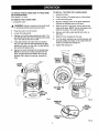
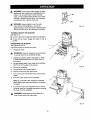
TO SWITCH FROM PLUNGE BASE TO FIXED BASE
OR D-HANDLE BASE
See Figures 4, 5, and 6.
TO INSTALL THE FIXED OR D-HANDLE BASE
1.
2.
Unplug the router,
Place the fixed or D-handle base on a flat surface.
TO REMOVE THE PLUNGE BASE
3.
Loosen the lockingarm.
1. Unplug the router.
4. Align the indicator arrow on the depth adjustment
ring with the indicator point on the base.
• 1, WARNING: Failure to unplug the tool could result
in accidental starting causing serious injury.
5.
Align the groove in the motor housingwith the tab
inside of the base. NOTE: The tab is located on the
inside of the base in line with the handle.
6.
Depress and hold the gold spindle lock button on
the motor.
2.
Place the router on a flat sudace.
3.
Loosen the locking knob.
4.
Depress and hold the gold spindle lock button. The
gold spindle lock button will not depress fully unless
it is in line with the hole in the collet.
5.
If the gold spindle lock button does not depress
fully, turn the collet nut while depressing the gold
spindle lock button. As they align, the gold spindle
lock button will depress fully.
6.
7. Slide the motor housing into the base.
8. Turn the depth adjusting ring counterclockwise ur_til
the gold spindle lock snaps out as it clears the rear
window, just below the locking arm.
9. Tighten the locking arm.
Remove the motor housing from the plunge base.
NOTE: As the motor is being removed from the
base, the gold spindle lock button has to be depressed until it clears the opening beneath the
GROOVEIN_
base.
MOTOR....._
HOUSING_
LOCKING
KNOB X
DEPTH
ADJUSTMENT
RING
TABINSIDE THE
BASE
__uTTPINDLE
GOLD
LOCK
ON
Fig. 4
Fig. 5
INDICATOR
ARROW
RING
Fig. 6
11
REMOVING/INSERTING
cu'n'ERS
See Figure 7,
Followthese steps to remove or insert cutters.
TO
LOOSEN
1. Unplug the router.
_,
WARNING: Failureto unplug the tool could result
in serious injurydue to accidental starting.
TO
TIGHTEN
CAUTION: To prevent damage to the spindle or
spindle lock, always allow motor to come to a
complete stop before engaging the spindle lock.
2.
Lay the router down on a workbench in order to
gain easy access to collet nut.
3.
Depress and hold the spindle lock button.
4.
Loosen the collet nut by turning it counterclockwise
with the wrench provided.
WARNING: If you are changing a cutter
immediately after use, be careful not to touch the
cutter or collet with your hands or fingers. Always
use the wrench provided.
5.
Choose one of these options:
• To remove the cutter: Remove the cutter from the
collet.
•
SPINDLE
LOCK
BU'FFON
To insert the cutter:
Fig. 7
a) Insert the shank of the cutter until the shank
bottoms out, then pull it out 1/16 in. (1.6 mm)
to allow for expansion when the bit gets hot.
ADJUSTING
DEPTH OF CUT
Proper depth of cut depends on several factors: the
horsepower of the router motor, the type of cutter, and
the type of wood. A lightweight, low horsepower router is
designed for making shallow cuts. A router with a high
horsepower rating can safely cut deeper. Small cutters,
such as veining bits with 1/16 in. (1.6 mm) cutting
diameters, are designed to remove only small amounts
of wood. Large cutters, such as straight-flute bits, are
made to remove larger amounts of wood. You can make
deeper cuts in soft woods, such as white pine, than in
hardwoods,like oak or maple.
b) Tighten the collet nut securely by turning it
clockwise with the wrench provided.
c) Release the spindle lock button.
WARNING: If the collet nut is not securely
tightened, the cutter may detach during use
causing serious personal injury.
• i, WARNING: Do not use cutters with undersized
shanks. Undersized shanks will not tighten properly
and could be thrown from the tool causing injury.
Based on these considerations,choose a depth of cut
that will not place excessive strain on the router motor. If
you find that extra force is needed or that the motor
speed stows down considerably,turn off the router and
reduce the depth of cut. Then, make the cut in two or
more passes.
_1= WARNING: Do not use cutters that are larger in
diameter than the opening in router base. Use of
such cutterswill come in contact with the router
base and damage both the cutter and router base.
This situation could also cause possibleloss of
controlor create other hazardous conditionsthat
could cause possible serious personal injury.
When routing a groove that is too deep to safely cut in
one pass, it is best to make the cut in several passes.
We recommend that cuts be made at a depth not
exceeding 1/8 in. (3.2 mm) and that several passes be
made to reach deeper cuts.
Adjustingthe depth of cut for the plunge router is
different from adjusting the depth of cut for the fixed
router.
12
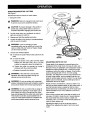
TOADJUSTDEPTHOFCUTFORPLUNGE
BASE
ROUTERS
See Figures 8, 9, 10 and 11.
Follow these steps to adjust depth of cut for plunge
base reuters.
1. Unplug the router.
WARNING: Failure to unplug the tool could result
in serious injury due to accidental starting.
2.
Place the router on a flat surface.
3.
Loosen the stop bar knob.
4.
Unlock the plunge lock lever.
5.
Plunge the router until the tip of the cutter touches
CUTTER
Fig. 9
STOP
BAR
KNOB
PLUNGE
LOCK
LEVER
\
Fig. 10
15. Plunge the router until the stop bar touches the
depth stop.
16. Lock the plunge lock lever to position the cutter at
the desired depth of cut.
Fig. 8
the flat surface.
6.
Lock the plunge lock lever.
7.
Move the stop bar down so that it touches the depth
stop.
8.
Tighten the stop bar knob securely.
9.
Set the depth indicatorto zero.
10. Loosen the stop bar knob.
11. Set the depth indicatorto the desired depth of cut.
Note: Each mark on the scale indicates 1/16 in.
(1.6 ram).
12. Tighten the stop bar knob securely.
13. Unlock the plunge lock lever.
14. Positionthe router so that the cutter can extend
below the subbase for desired depth of cut.
Fig. 11
13
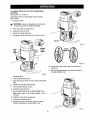
TO ADJUST DEPTH OF CUT FOR FIXED BASE
ROUTERS
See Figures 12, 13, and 14.
6.
Follow these steps to adjust depth of cut for fixed base
routers.
7.
1,
,_
with the indicator point on the base.
Position the router so that the cutter can extend
below the subbase for desired depth of cut.
Turn the depth adjustment ring to obtain the desired
depth of cut.
Unplug the router,
WARNING: Failure to unplug the tool could result
in sedous injury due to accidental starting.
2.
Place the router on a flat surface.
3.
Loosen the lockingarm.
4.
Turn the depth adjustment ring counterclockwise
until the tip of the cutter touchesthe flat surface.
5. Turn the depth indicator ring until the zero lines up
POINT IN__
RING
Fig. 13
8.
Tighten the locking arm securely.
Note: To adjust the depth of cut when the router is
mounted to a router table, turn the depth adjustment
ring untilthe cutter reaches the desired depth of cut.
LOCKING
ARM
Fig. 12
Fig, 14
14
A
WARNING: Always wear safety goggles or safety
glasses with side shields when operating this tool.
Failure to do so could result in dust, shavings,
chips, or loose particles being thrown in your eyes
resulting in possible serious injury. If the operation
is dusty, also wear a face or dust mask.
/
ON
OFF
,_
WARNING: Never attempt to use the router
motor without first installing it in one of the
approved bases. Failure to heed this warning could
result in personal injury and damage to the motor.
TURNING
ON/OFF
THE
Fig. 15
ROUTER
See Figure 15.
•
Toturnontherouter:Toggletheswitchtothelposition.
•
To turn off the router: Toggle
position.
OPERATING
the switch
to the O
THE ROUTER
See Figures 16 and 17.
Follow these steps to operate the router.
1.
Unplug the router.
WARNING: Failure to unplug the tool could result
in serious injury due to accidental starting.
2.
Tighten securely the cutter in the collet nut. Refer
to REMOVING/INSERTING CU'I-FERS earlier in
this manual.
3.
Set the desired depth of cut. Refer to ADJUSTING
DEPTH OF CUT earlier in this manual.
4.
Secure the workpiece.
5.
Plug the router into a power source.
6.
7.
Hold the router firmly with both hands.
Turn on the router and let the motor build to its full
speed.
8.
Feed the cutter slowly into the workpiece.
Fig. 16
Note: Do not let the cutter contact the workpiece
before starting the router and allowing it to devetop
full speed.
9.
Turn off the router upon completion of cut, and let
the motor come to a complete stop before removing
the router from the workpiece.
WARNING: Never place the router down on a
work surface before the cutter stops.
Fig. 17
15
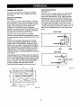
FEEDING THE ROUTER
The "secret" of professional routing lies in making a
careful set-up for the cut and in selecting the proper
rate of feed.
DIRECTION (EXTERNAL)
See Figure 18.
When routing, the cutter rotates clockwise. Therefore,
you should feed the router into the workpiece from left
to right. When you feed the router from left to right, the
rotation of the cutter pulls the router against the
workpiece. If you feed the router in the opposite
direction, the rotational forces of the spinning bit tend to
throw the router away from the workpiece. This action
could cause you to lose control of the router.
DIRECTION (INTERNAL)
See Figure 19.
Whenever you are routing a groove, your travel should
be in a direction that places whatever guide you are
using at the right-hand side. That is, when the guide is
positioned as shown in the first part of the figure, tool
travel should be from left to right and counterclockwise
around curves. When the guide is positioned as shown
in the second part of the figure, tool travel shouTd be
from right to left and clockwise around curves. If there is
a choice, the first setup is generally the easier to use. In
either case, the sideways thrust you use is against the
guide.
GUIDE OUTSIDE
The router motor and bit revolve in a clockwise
direction. This gives the tool a slight tendency to twist in
a counterclockwise direction, especially when the motor
revs up.
ROTATION
_"_
Because of the extremely high speed of bit rotation
during a proper feeding operation, there is very little
kickback under normal conditions. However, if the bit
strikes a knot, hard grain, or foreign object that affects
the normal progress of the cutting action, there will be a
slight kickback. This kickback is sufficient to spoil the
trueness of your cut if you are not prepared. Such e
kickback is always in the direction opposite the direction
of bit rotation.
ROTATION
_---"S_'_
FEED
ROTATION
_
THRUST
ROTATION_/-_
5
FEED
I"
,i L
-.l;L-
GUIDE
GUIDE INSIDE
To guard against such a kickback, plan your setup and
direction of feed so that you will always be thrusting the
tool--to hold it against whatever you are using to guide
the cut--in the same direction that the leading edge of
the bit is moving. In shod, the thrust should be in a
direction that keeps the sharp edges of the bit
continuously biting straight into new (uncut) wood.
6
'_
Fig. 19
2
-Tt
1/4in.to 1 in.
,
'
Fig. 18
16
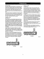
RATE OF FEED
The proper rate of feed depends on several factors: the
hardness and moisture content of the wood, the depth
of cut, and the cutting diameter of the bit. When cutting
shallow grooves in soft woods such as pine, you may
use a faster rate of feed. When making deep cuts in
hardwoods such as oak, you should use a slower rate of
feed.
Feeding Too Slow
See Figure 21.
It is also possible to spoil a cut by moving the router
forward too slowly. When you advance the router into
the work too slowly, the revolving bit does not dig into
new wood fast enough to take a bite; instead, it merely
scrapes away sawdust-like particles. Scraping produces
heat, which can glaze, burn, or mar the cut and in
extreme cases, can even overheat the bit ,destroying
its hardness.
The best rate of feed is one that does not slow down the
router motor more than one-third of its no load speed. If
you feed the router too fast, it will take large chips out of
the wood and leave gouge marks. If you feed the router
too slowly, it will scorch or burn the wood.
In addition, when the bit is scraping instead of cutting, it
is more difficult to control the router. With practically no
load on the motor, the bit revolves at close to top RPM,
and has a much greater than normal tendency to
bounce off the sides of the cut (especially if the wood
has a pronounced grain with hard and soft areas). As a
result, the cut produced may have rippled, instead of
straight, sides.
Feeding Too Fast
See Figure 20.
Clean, smooth routing and edge shaping can be done
only when the bit is revolving at a relatively high speed
and is taking very small bites to produce tiny, cleanly
severed chips. If you force the router to move forward
too fast, the RPM of the bit becomes slower than normal
in relation to its forward movement. As a result, the bit
must take bigger bites as it revolves. Bigger bites mean
bigger chips and a rougher finish. Also, because bigger
bites require more power, the router motor may become
ovedoaded.
Feeding too slow can also cause the router to take off
in a wrong direction from the intended line of cut.
Always grasp and hold the router firmly with both hands
when routing.
You can detect when you are feeding the router too
slowly by the runaway, high-pitched sound of the motor
or by feeling the wiggle of the bit in the cut.
Under extreme force-feeding conditions, the relative
RPM of the bit can become so slew--and the bites it
has to take so large--that chips will be partially knocked
off (rather than fully cut off). This causes splintering and
gouging of the workpiece.
The router is an extremely high-speed tool, and will
make clean, smooth cuts if allowed to run freely without
the overload of a forced feed. You can always detect
force feeding by the sound of the motor. Its high-pitched
whine will sound lower and stronger as it loses speed.
Also, the strain of holding the tool will be noticeably
increased.
TOO SLOW
Fig. 21
TOO FAST
Fig. 20
17
DEPTH OF CUT
See Figure 22.
As previously mentioned, the depth of cut is important
because it affects the rate of feed that, in turn, affects
the quality of the cut (and, also, the possibility of
damage to the router motor and bit). A deep cut
requires a slower feed than a shallow one. A cut that is
too deep causes you to slow the feed so much that the
bit no longer cuts; instead it scrapes.
Making a deep cut is never advisable. The smaller
bits---especially those only 1/16 inch (1.6 mm) in
diameter--are easily broken off when subjected to too
much side thrust. A large enough bit may not be broken,
but if the cut is too deep a rough cut will result--and it
may be very difficult to guide and control the bit as
desired. For these reasons, we recommend that you do
not exceed 1/8 in. depth of cut in a single pass,
regardless of the bit size or the softness or condition of
the workpiece.
Therefore, to make deeper cuts, make many successive
passes, Iowedng the bit 1/8 in. for each new pass. In
order to save time, do all the cutting necessary at one
depth setting before lowering the bit for the next pass.
This also assures a uniform depth when you complete
the final pass.
DEPTH
OF CUT
WIDTH
OF CUT
2ND,
PASS
1ST.
PASS
2ND. PASS
Fig. 22
18
|
_.
WARNING: When servicing, use only identical
Craftsman replacement parts. Use of any other
part may create a hazard or cause product
damage.
GENERAL
Only the parts shown on the parts list, are intended to
be repaired or replaced by the customer. All other parts
represent an important part of the double insulation
system and should be serviced only by a qualified
Sears service technician.
Avoid using solvents when cleaning plastic parts. Most
plastics are susceptible to damage from various types
of commercial solvents and may be damaged by their
use. Use clean cloths to remove dirt, carbon dust, etc.
CU'i-rERS
Get faster more accurate cutting results by keeping
cutters clean and sharp. Remove all accumulated pitch
and gum from cutters after each use.
When sharpening cutters, sharpen only the inside of the
cutting edge. Never grind the outside diameter. Be sure
when sharpening the end of a cutter to grind the
clearance angle the same as originally ground.
COLLET
From time to time, it also becomes necessary to clean
your coliet and collet nut. To do so, simply remove
collet nut from collet and clean the dust and chips that
have collected. Then return collet nut to its original
position.
ADJUSTING
_,
WARNING: Do not at any time let brake fluids,
gasoline, petroleum-based products, penetrating
oils, etc. come in contact with plastic parts. They
contain chemicals that can damage, weaken or
destroy plastic.
LOCKING
ARM TENSION
Over time and with repeated use, the locking arm may
become loose. When this occurs, tighten the elastic
stop nut slightly. The elastic stop nut should be loose
enough so there is some play in the locking arm when it
is in the open position. Make sure the motor housing
does not move up or down when clamped.
Electric tools used on fiberglass material, wallboard,
spackling compounds, or plaster are subject to
accelerated wear and possible premature failure
because the fiberglass chips and grindings are highly
abrasive to bearings, brushes, commutators, etc.
Consequently, we do not recommend using this tool for
extended work on these types of materials. However, if
you do work with any of these materials, it is extremely
important to clean the tool using compressed air.
NOTE: Do not over tighten the elastic stop nut. The
locking arm shouldclamp tightly to secure the motor
housing.
If the lockingarm becomes worn beyond adjustment, a
repair kit is available. Please contact your service
center to order the appropriate router locking arm repair
kit.
LUBRICATION
_L
WARNING: Always wear safety goggles or safety
glasses with side shields during power tool
operation or when blowing dust. If an operation is
dusty, also wear a dust mask. Failure to do so
could result in possible serious injury.
All of the bearings in this tool are lubricated with a
sufficientamount of high grade lubricantfor the life of
the unit under normal operating conditions.Therefore,
no further lubricationis required.
19
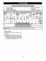
THE FOLLOWING
RECOMMENDED
ACCESSORIES
ARE
CURRENTLY
AVAILABLE
AT SEARS RETAIL STORES.
Dovetail Template
Rout-A-Form Pantograph
Butt Hinge Template
Template Set
Multi-Purpose Router Guide
Template Guide Bushing
COMBI-VEININGI CORE
NATION BIT
BOX
PANEL
BIT
STRAIGHT COMBIHINGE DOVETAIL RABBET OGEE,
ARBOR
COVE
BEAD
FACE
NATION MORTISING CUTTER
BIT
ROMAN 0
BIT,
:_UARTER-WITH BALL
STRAIGH'I
BIT
BIT
BITS
45°
ROUND BEARINGS
BEVEL
:HAMFER
BIT
2589
CUTTER
BIT
CUTTER
F
] V-GROOVE
CHAMFER
J
ij
WITH 2
BALL
BEARING_
(1/2 in. &
5/8 in.)
*25895
I* FORCARBIDETIPPEDEDGEFORMINGBITS I
* 25895FORCARBIDETIPPEDEDGEFORMINGBITS I
2589FORHIGHSPEEDSTEELEDGEFORMINGBITS
I
,_
WARNING:
ROUTER
The use of attachments or accessories not listed above might be hazardous.
TABLES
With a router table your router is converted into a highspeed shaper.
WARNING: Only use router tables with proper
guarding for the cutter and with "on board" switch
controlled receptacles (Part No. 9-25188). Failure to
use muter tables with appropriate safety features
could result in serious personalinjury.
2O
21
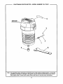
CRAFTSMAN
ROUTER
MOTOR
- MODEL
NUMBER
315.175341
SEENOTE
3
/
I
2
1
6
Note:
The assembly shown represents an Important part of the double insulated system. To avoid the
possibility of alteration or damage to the system, service should be performed by your nearest
Sears repair center. Contact your nearest Sears retail store for service center information.
22
CRAFTSMAN
I
ROUTER
MOTOR
- MODEL
NUMBER
315.175341
I
The model number will be found on a plate attached to the motor housing.Always mention the model
number in all correspondence regardingyour ROUTER MOTOR or when ordering repair parts.
SEE BACK
PAGE
FOR PARTS
ORDERING
INSTRUCTIONS
PARTS LIST
Key
No,
Part
No.
Description
1
690141001
Shaft Lock Spring ................................................................................................
1
2
671457001
Shaft Lock Pin ......................................................................................................
1
3
671245001
4
690190001
Collet Nut .............................................................................................................
1
5
940301011
Data Plate ............................................................................................................
1
6
671250001
Wrench ................................................................................................................
1
983000-435
Operator's Manual ...............................................................................................
1
* E-Ring**STD581018
Qty.
...........................................................................................
* Standard Hardware Item - May Be Purchased Locally
** Available from Div. 98 - Source 980,00
23
1
Your Home
For repair-in
your home-of
all major brand appliances,
lawn and garden equipment, or heating and cooling systems,
no matter who made it, no matter who sold it!
For the replacement parts, accessories and
owner's manuals that you need to do-it-yourself.
For Sears professional installation of home appliances
and items like garage door openers and water heaters.
1-800-4-MY-HOME
®
(1-800-469-4663)
Call anytime, day or night (U.SA
www.sears.com
and Canada)
www.sears.ca
Our Home
For repair of carry-in items like vacuums, lawn equipment,
and electronics, call or go on-line for the location of your nearest
Sears Parts & Repair Center.
1-800-488-1222
Call anytime,
day or night (U.S.A.
only)
www.sears.com
To purchase a protection agreement (U.S.A.)
or maintenance
agreement (Canada) on a product serviced
1-800-827-6655
(U.S.A.)
Para pedir servicio de reparaci6n
a domicilio, y para ordenar piezas:
1-888-SU-HOGAR
_
1-800-361-6665
Au Canada
(Canada)
pour service
1-800-LE-FOYER
(1-888-784-6427)
by Sears:
en fran(;:ais:
Mc
(1-800-533-6937)
www.sears.ca
SWAR$
® Registered Trademark I TM Trademark / su Service Mark of Sears, Roebuck and Co.
® Marca Registrada / TMMarca de F_brica I sM Marca de Servicio de Sears, RoebuCk and Co.
Mc Marque de commerce / MDMarque depos_e de Sears, Roebuck and Co.
© Seam, Roebuck
and Co.