1
Version 2.45
ISU AT Command Reference
Iridium Proprietary
Iridium Proprietary
20 June 2011
Version 2.45
i
Iridium Proprietary
ISU AT Command Reference
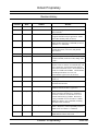
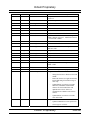
Revision History
Revision History
Version
Date
Author
Reason
1.0
06-Jul-99
Motorola author
Initial creation.
1.1
22-Oct-99
Motorola author
Fixed default/range values for +IPR, +WIRLP and
+DS commands.
1.2
9-Dec-99
Motorola author
Added more GSM 7.07 and GSM 7.05 commands
to support Starfish TrueSync application. Added
result codes summary table (section 9).
1.3
26-Jan-00
Motorola author
Added +G commands (section 6). Added Motorola
satellite product proprietary commands (section 9)
and Phase 2 +C commands.
1.4
21-Feb-02
Motorola author
Edited document to align with software releases
INC0620, RAC0620, LAC109G, and planned
future releases.
1.5
28-Mar-02
Motorola author
Refined edits after document inspection.
1.6
15-May-02
Motorola author
Updated S-Register Definitions in section 8, added
+CCLK command, clarified +COPS, change “ME”
to “ISU”.
1.7
11-Jun-02
Motorola author
Added definitions for RI and RTS terms. Updated
Sections 2 and 3 to aid user in command entry and
3-wire connection. Specified SAC0201 label for
9522 initial commercial release. Revised Phase III
defaults for AT&Kn and AT&Dn. Clarified Phase
III ATH implementation for voice call.
Consolidated S-register items in Section 8.
1.8
1-Jul-02
Motorola author
Incorporated feedback from ISLLC’s review of
version 1.7.
1.9
10-Oct-02
Motorola author
Added/updated AT commands for release
LAC0206 and SAC0206
1.10
18-Nov-02
Motorola author
Updated DAV description and added missing
extended command for DAV registration.
2.0
20-May-03
Steve Engelschall
Edited document to align with new software
releases LAC03xx and SAC03xx. Eliminated
references to software versions that were never
released commercially by Iridium. Reinserted
missing commands AT+CLCK and AT+CPWD.
Added new ‘Phase 4’ AT Commands, including
Short Burst Data commands.
2.1
8-April-05
Steve Engelschall
Edited document to include 9505A (“Monaco”) and
9522A (“Daytona”) in the compatibility matrices.
Added section for “Phase V” commands.
2.2
6-Feb-06
Colin Clark
Added Phase VI commands for SBD ring alert.
Added hardware failure result code.
Iridium Proprietary
20 June 2011
Version 2.45
ii
Iridium Proprietary
ISU AT Command Reference
Revision History
2.3
28-Feb-06
Colin Clark
Added Phase VI commands +CSQF and +CVMI.
2.4
10-Mar-06
Colin Clark
Incorporated feedback from ISLLC’s review of
version 2.3.
2.5
16-Mar-06
Colin Clark
Added description of +SBDDSC command.
2.6
30-Mar-06
Steve Engelschall
Edited notes associated with +IPR command.
2.7
5-Oct-07
Rob Tolfts
Added +CICCID command
2.8
13-Feb-08
Colin Clark
Added +CLIP and +CLIR commands
2.9
1-Apr-08
Mike Rudin
Added +ADJANT notification
2.10
21-Apr-08
Mike Rudin
Modify +ADJANT, add +ANTST
2.11
9-Jun-08
Mike Rudin
Improve +CCFC. Add +CCWA. Add changes from
Iridium’s branch version 2.7. Add H2/S2 versions
of +CCLK and +CPWD.
2.12
9-Jun-08
Stefan Kulick
Added +PCDA notification
2.13
22-Jul-08
Steve Haigh
Added +DPLCI notification
2.14
29-Jul-08
Steve Haigh
Added ‘number is SIM fixed dialling restricted’
CME error code
2.15
20-Aug-08
Mike Rudin
Clarify behaviour of +WIRLP (IID#1512)
2.16
22-Aug-08
Steve Haigh
Added +CSDT
2.17
28-Oct-08
Mike Rudin
Clarify +ANTST; add +WANTST
2.18
19-Nov-08
Mike Rudin
Added +CHLD and +XCSI
2.19
20-Nov-08
Vicky Larmour
Added +FEATURES and +FWVER
2.20
1-Dec-08
Mike Rudin
Clarify H2/S2 unsolicited message behaviour.
Added +CDSI.
2.21
4-Feb-09
Vicky Larmour
Added +KEY
2.22
23-Feb-09
Scott Mallonee
Updated Iridium logo on cover page
2.23
7-Apr-09
Marion Campbell
Changes:
2.24
12-Mar-09
Scott Mallonee
-
Changed references to H2/S2 to 9555 and
9522B.
-
Removed references to application board,
instead indicating if internal message or
9555 only.
-
Updated tables in section 4 to include
ISO07001, ISO08001 and ISO09001
releases for 9595A and 9522A and
updated table to show which AT
commands were added in each of these
releases.
-
Updated tables in section 4 to include
9555 and 9522B
Changes:
-
Updated –MSSTM to correct epoch note.
-
Correct typo in +CULK?
Iridium Proprietary
20 June 2011
Version 2.45
iii
Iridium Proprietary
ISU AT Command Reference
Revision History
2.25
14-Mar-09
Scott Mallonee
Added “Iridium Proprietary” to title, header, footer
2.26
19-May-09
Steve Hart
Corrected command descriptions for +CLCK (6.4
and 11.6). CS option enables or disables Phone lock
feature, it does not lock or unlock the phone – this
is provided by the +CPIN command
2.27
26-May-09
Scott Mallonee
Added comment to +CLIP, +CLIR, +CCWA,
+CHLD advising ISU support implemented but
network support TBD.
2.29
07-July-09
Scott Mallonee
Added <stat> field description to +CMGR
Added 003 to +CMS ERROR as being the same as
302. 003 report may be changed to 302 in a later
release.
2.30
17-July-09
Scott Mallonee
Added text to +CLIP section re: phone display
2.31
11-Aug-09
Scott Mallonee
Revised +CAR content to properly reflect product
availability
2.32
01-Sep-09
Scott Mallonee
Listed 9505A release availability of +CHLD
2.33
07-Sep-09
Steve Haigh
Added unsolicited +CAR for audio routing control
2.34
12-Feb-10
Vicky Larmour
Added unsolicited +CLPBK for audio loopback and
+CAPPV for application version
2.35
01-Mar-10
Vicky Larmour
Added new AT+CDEBUG command
2.36
08-Jun-10
Peter Laird
Added new AT+GPSSTA command for 9522B.
Updated response for AT+CLCC command.
2.37
23-Jul-10
Peter Laird
Added AT+GPSSTA and AT+GPSPOS for 9555A.
2.38
16-Aug-10
Scott Mallonee
Document date amended
2.39
12-Oct-10
Vicky Larmour
Added new AT+CBT command
Updated response for AT+CBC command.
Added AT+CAPBR, AT+CAPBW and
AT+CAPBD for application phonebook access
Added AT+HWVER for component hardware
revision reporting
Added AT+REBOOT to reboot handset
Added new AT+CSSSC command to execute
supplementary services shortcodes
Noted commands which do not support command
concatenation
2.40
28-Oct-10
Vicky Larmour
Correct description of AT+CLVL and AT+CAPB*
commands to reflect actual operation
2.41
09-Nov-2010
Vicky Larmour
Clarify description of AT+CCFC
2.42
17-Dec-10
Peter Goldsmith
Added key codes for AT+CKPD
2.43
26-Apr-11
Vicky Larmour
Added 9575 commands.
2.44
26-May-11
Vicky Larmour
Added new AT commands for 9575 config tool
2.45
27-May-11
Vicky Larmour
Updated new AT commands for 9575 config tool
Iridium Proprietary
20 June 2011
Version 2.45
iv
ISU AT Command Reference
Table of Contents
Table of Contents
1 Introduction .................................................................................................................... 1
1.1
1.2
1.3
Scope .................................................................................................................................................................. 1
Reference ............................................................................................................................................................ 1
Terms /and Abbreviations .................................................................................................................................. 1
2 Modem Overview ........................................................................................................... 5
2.1
2.2
2.3
2.4
2.5
2.6
DTE-ISU Interchange Circuits ........................................................................................................................... 5
9-Wire and 3-Wire Operation ............................................................................................................................. 5
Configuration Settings ........................................................................................................................................ 5
Mode of Operation ............................................................................................................................................. 5
Hardware Failure Reporting ............................................................................................................................... 6
Ring Indicate Signal ........................................................................................................................................... 6
3 Command Overview ...................................................................................................... 7
3.1
3.2
3.3
3.4
3.5
3.6
Command Types................................................................................................................................................. 7
Basic Commands ................................................................................................................................................ 7
Extended Commands .......................................................................................................................................... 7
Command and Response Characters .................................................................................................................. 8
Command Entry ................................................................................................................................................. 9
Command Responses........................................................................................................................................ 10
4 Phased Implementation by Software Release ........................................................... 11
5 Phase I AT Commands ................................................................................................ 16
5.1
5.2
5.3
5.4
5.5
5.6
5.7
5.8
5.9
5.10
5.11
5.12
5.13
5.14
5.15
5.16
5.17
AT - ATtention Code........................................................................................................................................ 16
A/ - Repeat Last Command .............................................................................................................................. 16
+++ - Escape Sequence .................................................................................................................................... 16
A - Answer (Initial implementation; revised in Phase III) ............................................................................... 16
Bn - Communication Standards........................................................................................................................ 16
Cn - Carrier Control.......................................................................................................................................... 16
D - Dial (Initial implementation; revised in Phase III) ..................................................................................... 17
5.7.1
Direct Dial From Phonebook (Initial implementation; revised in Phase III) ..................................... 17
En - Echo .......................................................................................................................................................... 18
Fn - Line Modulation........................................................................................................................................ 18
Hn - Hangup (Initial implementation; revised in Phase III) ............................................................................. 18
In – Identification (Initial implemenation; revised in Phase VI) ...................................................................... 18
Ln - Loudspeaker Volume ................................................................................................................................ 18
Mn - Speaker Control ....................................................................................................................................... 18
Nn - Automode Enable ..................................................................................................................................... 19
On - Online ....................................................................................................................................................... 19
P - Pulse Dial .................................................................................................................................................... 19
Qn - Quiet Mode............................................................................................................................................... 19
Iridium Proprietary
20 June 2011
Version 2.45
v
ISU AT Command Reference
5.18
5.19
5.20
5.21
5.22
5.23
5.24
5.25
5.26
5.27
5.28
5.29
5.30
5.31
5.32
5.33
5.34
5.35
5.36
5.37
5.38
5.39
5.40
5.41
5.42
5.43
5.44
5.45
5.46
5.47
5.48
5.49
5.50
5.51
5.52
5.53
5.54
5.55
5.56
5.57
5.58
5.59
Table of Contents
S0=n - Auto-Answer (Initial implementation; revised in Phase III) ................................................................. 19
T - Tone Dial .................................................................................................................................................... 19
Vn - Verbose Mode .......................................................................................................................................... 20
Wn - Error Correction Message Control .......................................................................................................... 20
Xn - Extended Result Codes (Initial implementation; revised in Phase III) ..................................................... 20
Yn - Long Space Disconnect ............................................................................................................................ 20
Zn - Soft Reset .................................................................................................................................................. 20
&Cn - DCD Option .......................................................................................................................................... 21
&Dn - DTR Option (Initial implementation; revised in Phase III) ................................................................... 21
&Fn - Restore Factory Settings ........................................................................................................................ 21
&Gn - Guard Tone............................................................................................................................................ 21
&Jn - Jack Control ............................................................................................................................................ 22
&Kn - Flow Control ......................................................................................................................................... 22
&Ln - Leased Line Operation ........................................................................................................................... 22
&Mn - Asynchronous/Synchronous Mode ....................................................................................................... 22
&Pn - Pulse Dial Make/Break Ratio................................................................................................................. 22
&Qn - Sync/Async Mode ................................................................................................................................. 22
&Rn - RTS/CTS Option ................................................................................................................................... 24
&Sn - DSR Override ........................................................................................................................................ 24
&V - View Active and Stored Configuration ................................................................................................... 24
&Wn - Store Active Configuration .................................................................................................................. 24
&Xn - Select Synchronous Clock ..................................................................................................................... 24
&Yn - Designate Default Reset Profile ............................................................................................................ 24
\An - MNP Block Size...................................................................................................................................... 24
\Bn - Transmit Break ........................................................................................................................................ 25
\Gn - XON/XOFF Flow Control ...................................................................................................................... 25
\Jn - DTE Auto Rate ......................................................................................................................................... 25
\Kn - Control Break .......................................................................................................................................... 25
\Nn - Link Type ................................................................................................................................................ 25
%Cn - Compression Control ............................................................................................................................ 26
%En - Auto Retrain .......................................................................................................................................... 26
%R - Display Registers .................................................................................................................................... 26
*Pn - Power Phone ........................................................................................................................................... 26
+CBST - Select Bearer Service Type ............................................................................................................... 27
+CGMI - Manufacturer Identification .............................................................................................................. 27
+CGMM - Model Identification ....................................................................................................................... 27
+CGMR - Revision .......................................................................................................................................... 28
+CGSN - Serial Number .................................................................................................................................. 28
+CMEE - Report Mobile Equipment Error ...................................................................................................... 28
+CPAS - Phone Activity Status ........................................................................................................................ 29
+CR - Service Reporting Control ..................................................................................................................... 30
+CRC - Cellular Result Codes (Initial implementation; revised in Phase III).................................................. 30
Iridium Proprietary
20 June 2011
Version 2.45
vi
ISU AT Command Reference
Table of Contents
5.60 +DS - Set Data Compression Function............................................................................................................. 31
5.61 +DR - Data Compression Report Level............................................................................................................ 31
5.62 +IPR - Fixed DTE Rate (Initial implementation; revised in Phase VI) ............................................................ 32
6 Phase II AT Commands ............................................................................................... 33
6.1
6.2
6.3
6.4
6.5
6.6
6.7
6.8
6.9
6.10
6.11
6.12
6.13
6.14
6.15
6.16
6.17
6.18
6.19
6.20
6.21
6.22
6.23
6.24
6.25
6.26
6.27
6.28
6.29
6.30
6.31
+CBC - Battery Charge (Initial implementation; revised in Phase III) ............................................................ 33
+CEER - Extended Error Report ...................................................................................................................... 33
+CHUP - Hangup call ...................................................................................................................................... 33
+CLCK - Facility Lock (Phase II version) ....................................................................................................... 34
+CMGD - Delete SMS Message ...................................................................................................................... 34
+CMGF - SMS Message Format ...................................................................................................................... 36
+CMGL - List SMS Messages ......................................................................................................................... 37
+CMGR - Read SMS Message......................................................................................................................... 37
+CMGS - Send SMS Message ......................................................................................................................... 38
+CMGW - Write SMS Message To Memory................................................................................................... 38
+CMOD - Call Mode ....................................................................................................................................... 38
+CNMI - New SMS Message Indications to DTE ........................................................................................... 40
+COPS - Operator Select.................................................................................................................................. 41
+CPBF - Find phonebook entries ..................................................................................................................... 42
+CPBR - Read phonebook entries .................................................................................................................... 42
+CPBS - Select phonebook storage .................................................................................................................. 43
+CPBW - Write phonebook entry .................................................................................................................... 43
+CPIN - Enter PIN ........................................................................................................................................... 44
+CPMS - Select Preferred SMS Message Storage ........................................................................................... 45
+CPWD - Change Password (Phase II version) ............................................................................................... 45
+CREG - Network Registration ....................................................................................................................... 46
+CSCA - SMS Service Center Address ........................................................................................................... 47
+CSCB - Select Cell Broadcast Message Types .............................................................................................. 47
+CSCS - Select TE Character Set..................................................................................................................... 47
+CSMS - Select SMS Message Service ........................................................................................................... 48
+CSTA - Select Type of Address ..................................................................................................................... 48
+GMI - Manufacturer Identification................................................................................................................. 48
+GMM - Model Identification .......................................................................................................................... 49
+GMR - Revision ............................................................................................................................................. 49
+GSN - Serial Number ..................................................................................................................................... 49
+GCAP - General Capabilities ......................................................................................................................... 49
7 Phase III AT Commands .............................................................................................. 50
7.1
7.2
7.3
7.4
7.5
A - Answer (Revised) ....................................................................................................................................... 50
D - Dial (Revised) ............................................................................................................................................ 50
7.2.1
Direct Dial From Phonebook (Revised) ............................................................................................. 51
Hn - Hangup (Revised) ..................................................................................................................................... 51
S0=n - Auto-Answer (Revised) ........................................................................................................................ 51
Xn - Extended Result Codes (Revised) ............................................................................................................ 52
Iridium Proprietary
20 June 2011
Version 2.45
vii
ISU AT Command Reference
7.6
7.7
7.8
7.9
7.10
7.11
7.12
7.13
7.14
7.15
7.16
7.17
Table of Contents
&Dn - DTR Option (Revised) .......................................................................................................................... 52
+CBC - Battery Charge (Revised) .................................................................................................................... 53
+CSQ - Signal Quality (Initial implementation; revised in Phase VI) ............................................................. 54
+CLVL - Loudspeaker Volume Level Control ................................................................................................ 55
+CMUT - Mute Control ................................................................................................................................... 55
+CRC - Cellular Result Codes (Revised) ......................................................................................................... 57
+CVHU - Voice Hangup Control ..................................................................................................................... 57
+CCLK - Real-Time Clock .............................................................................................................................. 58
-MSVTS - DTMF Generation in Voice Call .................................................................................................... 58
-MSVTR - DTMF Received in Voice Call....................................................................................................... 59
-MSVLS - Local DTMF Feedback Selection ................................................................................................... 59
-MSSTM - Request System Time .................................................................................................................... 60
8 Phase IV AT Commands ............................................................................................. 61
8.1
8.2
8.3
8.4
8.5
8.6
8.7
8.8
8.9
8.10
8.11
8.12
8.13
8.14
8.15
8.16
8.17
8.18
8.19
8.20
–MSGEO - Request Geolocation ..................................................................................................................... 61
–MSGEOS - Request Geolocation, spherical co-ordinates .............................................................................. 61
+CCFC - Call Forward service ......................................................................................................................... 61
+CLCC - Request Current Call Status .............................................................................................................. 63
+CNUM - Read MSISDN Numbers ................................................................................................................. 63
+CSSSC – Supplementary Services Short Code .............................................................................................. 64
+WIRLP - Iridium Radio Link Protocol........................................................................................................... 64
+WFRNG - Force IRLP Renegotiation ............................................................................................................ 66
+WTM - IRLP Test Mode ................................................................................................................................ 66
+WDLDM - IRLP Dynamic Link Delay Measurement ................................................................................... 67
+WDAV - Register or Deregister an RS232 DAV Data Peripheral ................................................................. 67
+SBDWB - Short Burst Data: Write Binary Data to the ISU ........................................................................... 68
+SBDRB - Short Burst Data: Read Binary Data from ISU .............................................................................. 69
+SBDWT - Short Burst Data: Write a Text Message to the ISU (Initial implementation; revised in Phase VI)
69
+SBDRT - Short Burst Data: Read a Text Message from the ISU ................................................................... 70
+SBDI - Short Burst Data: Initiate an SBD Session (Initial implementation; revised in Phase VI)................. 70
+SBDD - Short Burst Data: Clear SBD Message Buffer(s) ............................................................................. 72
+SBDC - Short Burst Data: Clear SBD MOMSN ............................................................................................ 72
+SBDS - Short Burst Data: Status .................................................................................................................... 73
+SBDTC - Short Burst Data: Transfer MO Buffer to MT Buffer .................................................................... 73
9 Phase V AT Commands .............................................................................................. 74
9.1
+CAR - Audio Output Control ......................................................................................................................... 74
10 Phase VI AT Commands ............................................................................................. 75
10.1
10.2
10.3
10.4
In – Identification (Revised) ............................................................................................................................. 75
+CIER – Indicator Event Reporting ................................................................................................................. 75
+CRIS – Ring Indication Status ....................................................................................................................... 76
+CSQ[F] – Signal Quality (Revised)................................................................................................................ 76
Iridium Proprietary
20 June 2011
Version 2.45
viii
ISU AT Command Reference
10.5
10.6
10.7
10.8
10.9
10.10
10.11
10.12
10.13
10.14
10.15
10.16
10.17
10.18
10.19
Table of Contents
+CULK – Unlock ............................................................................................................................................. 77
+CVMI – Voicemail Indication ........................................................................................................................ 78
+CICCID – Read ICC ID from sim .................................................................................................................. 78
+CLIP – Calling Line Identification Presentation ............................................................................................ 78
+CLIR – Calling Line Identification Restriction .............................................................................................. 79
+IPR - Fixed DTE Rate (Revised) .................................................................................................................... 80
+SBDWT - Short Burst Data: Write a Text Message to the ISU (Revised) ..................................................... 80
+SBDDET - Short Burst Data: Detach ............................................................................................................. 81
+SBDI - Short Burst Data: Initiate an SBD Session (Revised) ........................................................................ 82
+SBDIX[A] - Short Burst Data: Initiate an SBD Session Extended ................................................................ 83
+SBDDSC - Short Burst Data: Delivery Short Code ....................................................................................... 85
+SBDMTA - Short Burst Data: Mobile-Terminated Alert ............................................................................... 85
+SBDREG - Short Burst Data: Network Registration...................................................................................... 86
+SBDAREG - Short Burst Data: Automatic Registration ................................................................................ 87
+SBDSX - Short Burst Data: Status Extended ................................................................................................. 89
11 Phase VII AT Commands ............................................................................................ 90
11.1
11.2
11.3
11.4
11.5
11.6
11.7
11.8
11.9
11.10
11.11
11.12
11.13
11.14
11.15
11.16
11.17
11.18
11.19
11.20
11.21
11.22
11.23
11.24
11.25
11.26
+ADJANT – User Antenna Adjustment Required ........................................................................................... 90
+WANTST, +ANTST – Antenna status........................................................................................................... 90
+PCDA – Pending call drop alert ..................................................................................................................... 91
+DPLCI – DPL Call Indication ........................................................................................................................ 92
+CCWA - Call Waiting service ........................................................................................................................ 93
+CLCK - Facility Lock (9555/9522B version) ................................................................................................ 94
+CPWD - Change Password (9555/9522B version)......................................................................................... 96
+CSDT – Sidetone............................................................................................................................................ 97
+CHLD – Call Hold and Multiparty................................................................................................................. 97
+XCSI – Extended Call State Information ....................................................................................................... 98
+FEATURES – List supported extended features .......................................................................................... 100
+FWVER – List all software revisions........................................................................................................... 100
+HWVER – List all hardware revisions ......................................................................................................... 100
+LFWVER – Internal boot loader version ..................................................................................................... 101
+CDSI – Report SMS status ........................................................................................................................... 101
+KEY – Control unsolicited key press indications......................................................................................... 101
+CKPD – Insert key press via AT interface ................................................................................................... 102
+CLPBK – Audio loopback initiation ............................................................................................................ 102
+CAPPV – Application version information .................................................................................................. 103
+CDEBUG – Configure Crash Debug behaviour........................................................................................... 103
+GPSSTA – Configure GPS status (9522B) .................................................................................................. 104
+GPSSTA – Configure GPS status (9555A) .................................................................................................. 104
+GPSSTA – Configure GPS status (9575) ..................................................................................................... 105
+GPSPOS – Report GPS position (9555A) .................................................................................................... 105
+GPSPOS – Report GPS position (9575)....................................................................................................... 106
+GPSUPD – Update GPS position (9575 only) ............................................................................................. 106
Iridium Proprietary
20 June 2011
Version 2.45
ix
ISU AT Command Reference
11.27
11.28
11.29
11.30
11.31
11.32
11.33
11.34
11.35
11.36
11.37
Table of Contents
+QGPS – Send Quick GPS message (9575 only)........................................................................................... 106
+CBT - Battery Temperature.......................................................................................................................... 107
+CAPBR – Read application phonebook entry .............................................................................................. 107
+CAPBW – Write application phonebook entry ............................................................................................ 107
+CAPBD – Delete application phonebook entry............................................................................................ 107
+REBOOT – Reboot handset ......................................................................................................................... 108
+ LBSECR – Emergency call recipient .......................................................................................................... 108
+ LBSECRD – Emergency call recipient ....................................................................................................... 108
+ LBSEMR – Emergency message recipients ................................................................................................ 108
+ LBSECMD – Delete emergency message recipients .................................................................................. 109
+ LBSEDM – Emergency delivery mode....................................................................................................... 109
12 S-Register Definitions ............................................................................................... 111
12.1 S-Register Commands .................................................................................................................................... 111
12.1.1 Sr - Direct S-Register Reference ...................................................................................................... 111
12.1.2 Sr? - Direct S-Register Read ............................................................................................................ 111
12.1.3 Sr=n - Direct S-Register Write ......................................................................................................... 111
12.1.4 ? - Referenced S-Register Read........................................................................................................ 111
12.1.5 =n - Referenced S-Register Write .................................................................................................... 111
12.2 Standard S-Registers ...................................................................................................................................... 112
12.3 Iridium Specific S-Register Extensions .......................................................................................................... 114
13 Summary of Result Codes ........................................................................................ 116
14 Informative Examples................................................................................................ 119
14.1
14.2
14.3
14.4
14.5
14.6
14.7
Unit Identification .......................................................................................................................................... 119
Originating a Data Call ................................................................................................................................... 119
Answering a Data Call.................................................................................................................................... 119
Disconnecting a Data Call .............................................................................................................................. 120
Originating and Disconnecting a Voice Call .................................................................................................. 120
Coordination of +CLCC and +CPAS responses ............................................................................................. 120
Usage examples of +CCFC command............................................................................................................ 121
Iridium Proprietary
20 June 2011
Version 2.45
x
ISU AT Command Reference
Introduction
1 Introduction
1.1
Scope
This document is intended as a reference guide to the usage of the AT command set for the IridiumTM/SM subscriber unit. This document only applies to the Motorola satellite series.
The intended audience for this document are the field test engineers, product and intelligent peripheral
developers.
1.2
Reference
[1]
ITU-T Recommendation V.25ter, 08/95.
[2]
ETS 300 642: Digital Cellular Telecommunications System (Phase 2); AT Command Set for GSM
Mobile Equipment (GSM 07.07).
[3]
ETS 300 585: Digital Cellular Telecommunications System (Phase 2); Use of DTE-DCE Interface
SMS and CBS (GSM 07.05)
[4]
ITU-T Recommendation V.24, 03/93.
1.3
Terms /and Abbreviations
Asynchronous
A serial data transmission method that uses Start and Stop bits to synchronize reception.
AT Commands
A group of commands that can be sent by a terminal or host computer to control the ISU in Command
mode.
Baud
One signalling element per second. This is a measure of the signalling rate on the telephone line. It
should not be confused with Bits Per Second (bps) which can differ from the Baud rate.
BCD
Binary Coded Decimal
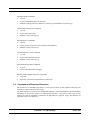
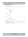
Bit Mapped Registers
Bit mapping is a technique that allows a single S-Register to hold up to 8 binary variables e.g.:
Reg Type
Val Default Function
S14 Bit Mapped
170
Register S14 is a bit-mapped register
and provides the following functions:
Bit 0
Reserved
Bit 1
Echo commands to DTE
Bit 2
Responses
Bit 3
Word or number responses
Bit 4
Reserved
Bit 5
Dialing method
Bit 6
Reserved
Iridium Proprietary
20 June 2011
Version 2.45
1
ISU AT Command Reference
Introduction
Bit 7
Answer/Originate operation
Iridium Proprietary
20 June 2011
Version 2.45
2
ISU AT Command Reference
Introduction
CI
Cell Identifier
CTS
(V.24 Signal) Clear To Send. This signal is normally used in controlling the flow of data to the ISU.
(See RTS)
DCD
(V.24 Signal) Data Carrier Detect. This is a signal from the ISU that indicates that it is connected to
the far-end modem for data transfer.
DCE
Data Communications Equipment, i.e., a data adaptor or modem. In this product, DCE refers to the
ISU.
DSR
(V.24 Signal) Data Set Ready. This signal, from the ISU, indicates the readiness of the phone to
receive data.
DTE
Data Terminal Equipment, such as a dumb terminal, or a PC running communications software.
DTR
(V.24 Signal) Data Terminal Ready. A signal from the DTE to the ISU. Can be used to terminate
calls.
ESS
ETC SBD Subsystem (synonymous with GSS)
ETC
Earth Terminal Controller
ETSI
European Telecommunications Standards Institute.
FA
Field Application
GSM
Global System for Mobile communications.
GSS
Gateway SBD Subsystem (synonymous with ESS)
IRLP
Iridium Radio Link Protocol
ISU
Individual Subscriber Unit
LAC
Location Area Code
Modem
MOdulator/DEModulator. A device used to convert digital signals to analog signals for transmission
and reception of telephone lines.
MO
Iridium Proprietary
20 June 2011
Version 2.45
3
ISU AT Command Reference
Introduction
Mobile Originated (for Short Burst Data)
MOMSN
Mobile Originated Message Sequence Number (for Short Burst Data)
MT
Mobile Terminated (for Short Burst Data)
MTMSN
Mobile Terminated Message Sequence Number (for Short Burst Data)
RI
(V.24 Signal) Ring Indicate. This is a signal from the ISU which indicates that an incoming call is
ringing or that an MT SBD message is present at the ESS.
RP
Relay Protocol (used in SMS).
RTS
(V.24 Signal) Request To Send. This signal is normally used in controlling the flow of data from the
ISU.
SBD
Short Burst Data
SMS
SMS Short Message Service.
SMSSC
Short Message Service - Service Centre (used in SMS).
TP
Transfer Protocol (used in SMS).
XON/XOFF
A standard method of controlling the flow of data to and from a ISU to prevent overflow/overrun
conditions.
Iridium Proprietary
20 June 2011
Version 2.45
4
ISU AT Command Reference
Modem Overview
2 Modem Overview
2.1
DTE-ISU Interchange Circuits
The communication between the ISU (Iridium Subscriber Unit) and the DTE (Data Terminal Equipment)
follows the ITU-T V.24 (RS-232) recommendation. Please see reference [4] for details.
2.2
9-Wire and 3-Wire Operation
The ISU supports a full 9-wire interface to the DTE, incorporating hardware handshaking and flow control.
A 3-wire DTE interface, where only transmit, receive, and ground signals are used, is supported in those
ISUs where the AT&D0 command has been revised to ignore the DTR (Data Terminal Ready) signal.
When operating with a 3-wire connection, the following limitations apply:
AT&Dn must be set to AT&D0 to ignore the DTR input from the DTE, as it will not be present as an
input from the DTE
AT&Kn must be set to AT&K0 for no flow control or AT&K4 for XON/XOFF software flow control, as
RTS (Request To Send) and CTS (Clear To Send) hardware flow control signals will not be present
AT&Cn setting will have no affect, as DCD (Data Carrier Detect) output to the DTE will not be present
AT&Sn setting will have no affect, as DSR (Data Set Ready) output to the DTE will not be present
RI (Ring Indicate) output to the DTE will not be present
2.3
Configuration Settings
The ISU allows the DTE to configure the communication parameters. The three configuration types are
active, factory default, and stored.
The active configuration is the set of parameters currently in use. They can be changed by the DTE
individually via specific AT commands.
The factory default configuration is stored in permanent memory. This configuration can be recalled at any
time by through use of the AT&Fn command.
Two groups of settings, or “profiles”, can be stored as user-defined configuration. The DTE first creates
desired active configurations and then writes them to memory using the AT&Wn command. These profiles
can be designated to be loaded as the active configuration upon ISU power-up through use of the AT&Yn
command. Similarly, the ISU can be reset without loss of power to these profiles through use of the ATZn
command.
Most of the configuration settings are reflected in “S-register” locations. S-register is the term used by
Hayes-compatible modems for a specific physical location in memory.
2.4
Mode of Operation
The ISU is always in one of two modes: command mode or data mode.
When the ISU is in command mode, AT commands can be entered to control the phone. Note that
command mode can be accessed while on-hook (i.e. not in a call) or in-call.
When in data mode, the ISU is connected to a remote system and any characters sent to it will be
transmitted to the remote system. Note that data mode can be only accessed while in-call.
While in-call, the Escape Sequence (+++) is used to enter the command mode. The Online command
Iridium Proprietary
20 June 2011
Version 2.45
5
ISU AT Command Reference
Modem Overview
(ATOn) is used to return to the data mode. These mode transitions are made without terminating the call.
2.5
Hardware Failure Reporting
If the ISU detects a hardware problem during initialisation, the ISU may be unable to function correctly.
The ISU notifies the DTE of this situation by issuing an unsolicited result code at the end of initialisation:
HARDWARE FAILURE:<subsys>,<error>
where <subsys> identifies the software subsystem that detected the error, and <error> is the
subsystem-specific error code.
Any AT commands that cannot be handled in the failure condition will terminate with result code 4
(“ERROR”).
2.6
Ring Indicate Signal
Prior to Implementation Phase VI (see section 4), the RI (Ring Indicate) signal was used only to indicate
the presence of an incoming telephony call. From Phase VI, it is also used to indicate reception of an SBD
Ring Alert. This section describes the behaviour of the RI signal in devices supporting both telephony and
SBD ring alerts.
The Ring Indicate signal indicates that an incoming telephony call is ringing, or that an SBD ring alert has
been received. It is accompanied by the unsolicited announcements RING or SBDRING.
In the case of an incoming telephony call, which may be a voice, data or fax call, the RI signal is active for
as long as the call is offered. The RI signal is deactivated when the call is answered or when it is no longer
offered (e.g. the originator terminates the call before it is answered). A RING announcement is issued if
the DTE interface is in command mode. (This behaviour is identical to pre-phase VI versions of 9505A
and 9522A).
In the case of an SBD ring alert, which indicates that there is at least one SBD message at the gateway
awaiting collection, then provided that SBD ring alerts are enabled (see +SBDMTA), the RI signal is
activated on reception of the SBD ring alert. It is held active for a period of 5 seconds from reception of
the SBD ring alert, or until the DTE initiates an SBD session to retrieve the waiting message, whichever
occurs first. An SBDRING announcement is issued if the DTE interface is in command mode, or when it
next returns to command mode. (This behaviour is identical to the 9601).
If the ISU receives an SBD ring alert at the same time as an incoming telephony call, the RI signal
combines both of the above behaviours, remaining active as long as required by either the telephony or
SBD criteria.
The +CRIS command may be used to query the ISU as to the reason for the most recent assertion of the RI
signal.
Iridium Proprietary
20 June 2011
Version 2.45
6
ISU AT Command Reference
Command Overview
3 Command Overview
3.1
Command Types
The ISU employs two principle types of AT commands: basic and extended. The two types have differing
syntax used to query and adjust their settings. They also have unique reference standards.
A specific basic AT command is used to reference S-registers and query and adjust their settings. Its
syntax is similar to that of extended AT commands.
3.2
Basic Commands
Basic commands are industry standard and originally developed for Hayes-compatible PSTN modems. In
many cases, basic commands consist of a single ASCII alpha character.
In other cases, a special character precedes the alpha character. Prefix characters used in ISU basic
commands include &, \, %, and *.
Most alpha characters in basic commands are followed by a numeric parameter, n. To adjust its setting, a
basic command is entered with the appropriate numeric value of n. Note that if the numeric parameter n is
omitted from the basic command entry, a value of zero is assumed for n. For example, ATXn is set to a
value of 4 by entering ATX4, whereas it is set to value of 0 by entering either ATX0 or ATX.
To query a basic command setting, the AT&V command is entered to view the active configuration of a
group of basic commands.
Some basic commands listed in this document are marked with “No action, compatibility only”. In these
cases, the basic command is accepted in the same fashion as is with other modems, but has no effect on the
operation of the ISU, since it has no meaning in the IridiumTM/SM environment.
3.3
Extended Commands
Extended commands perform actions or set parameters that extend the capability of the ISU beyond that
which is allowed by basic commands. In some cases, they were designed for non-PSTN networks, such as
the GSM network.
Most extended commands include a prefix of + followed by a single alpha character. Prefixes used in ISU
extended commands include +C, +D, +G, +I, and +S. Extended commands designed specifically for the
Motorola Satellite Series product line include a -MS prefix.
Most extended commands include three alpha characters after the prefix, but some commands include just
one or two alpha characters after the prefix.
Some extended commands have a single execution mode. No further syntax is added after the prefix and
body of the command. For example, AT+GSN is entered as shown to query the ISU for its assigned serial
number (i.e. IMEI).
Some extended commands incorporate a test mode to query their range of valid responses. For example,
AT+CBC is entered as shown in execution mode to query the ISU for its battery connection and charge
status. The command is entered as AT+CBC=? in test mode to query its range of valid responses.
Some extended commands incorporate set, read, and test modes. For example, AT-MSVTR is entered as
AT-MSVTR=n in set mode to enable/disable receipt of DTMF messages. It is entered as AT-MSVTR? in
read mode to query its current setting and is entered as AT-MSVTR=? in test mode to query its range of
valid settings.
Extended commands are grouped as shown below.
Iridium Proprietary
20 June 2011
Version 2.45
7
ISU AT Command Reference
Command Overview
Extended Cellular Commands
+C prefix
Used for GSM cellular phone-like functions
Standards: ETSI specifications GSM 07.07 (reference [2]) and GSM 07.05 (reference [3])
Extended Data Compression Commands
+D prefix
Used for data compression
Standard: V.25ter (reference [1])
Extended Generic Commands
+G prefix
Used for generic DCE issues such as identities and capabilities
Standard: V.25ter (reference [1])
Extended Interface Control Commands
+I prefix
Used to control the DTE interface
Standard: V.25ter (reference [1])
Extended Short Burst Data Commands
+S prefix
Used for Short Burst Data messaging
Motorola Satellite Product Proprietary Commands
-MS prefix
Proprietary to the Motorola Satellite Series product line
3.4
Command and Response Characters
The execution of a command string follows a left-to-right execution of each command followed by the
reporting of a result code for the entire string.
The ASCII character set (CCITT T.50 International Alphabet 5, American Standard Code for Information
Interchange) is used for the issuance of commands and responses. Only the low-order 7 bits of each
character are used for commands or parameters; the high-order bit is ignored. Upper case characters are
equivalent to lower case characters.
Iridium Proprietary
20 June 2011
Version 2.45
8
ISU AT Command Reference
3.5
Command Overview
Command Entry
An AT command is a string of characters sent by the DTE to the ISU while the ISU is in command mode.
A command string has a prefix, a body, and a terminator. The prefix consists of the ASCII characters AT
or at. The body is a string of commands restricted to printable ASCII characters. The default terminator
is the <CR> character.
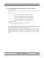
AT command entry syntax is critical, and the following rules apply:
All commands (apart from A/ and +++) begin with a prefix of AT or at.
The commands in a command string (apart from A/ and +++) are executed only after the return or
enter key is pressed.
Use of upper or lower case letters is allowed, but not a combination of both.
The maximum number of characters in a command string is 128.
If the numeric parameter n is omitted from the basic command entry, a value of zero is assumed for n.
If an optional parameter is omitted from an extended command, the current value is implied. Optional
parameters are enclosed by square brackets ([...]) in this document.
Multiple commands can be concatenated onto a single command line by separating the additional nonprefixed commands with a space or a semicolon or with no separator whatsoever. In the 9555 and
9555A Handsets, some commands do not support concatenation in this way and these are identified in
this document with the note “This command does not support command concatenation in the 9555 and
9555A Handsets”.
Spaces entered into a command string for clarity between the AT prefix and the body of the command
are ignored. Likewise, spaces entered for clarity within the command body between alpha characters
and decimal parameters are ignored.
The backspace or delete keys can typically be used to edit commands.
Characters that precede the AT prefix are ignored.
Ctrl-x can be used to abort a command line input.
Consider the following six commands to be entered in a single command line:
ATX0
(set basic command ATXn to n=0)
AT&V
(execute basic command AT&V)
AT+GSN
(execute extended command AT+GSN)
AT+CMEE=?
(query the valid range of responses of extended command AT+CMEE)
AT+CPBR=1,12 (execute extended command AT+CPBR with parameters 1 and 12)
AT-MSVTR?
(query the current setting of extended command AT-MSVTR)
The following are valid single command line entries of above six commands:
at x 0 &v +gsn +cmee=? +cpbr=1,12 -msvtr? (all lower case)
AT X 0 &V +GSN +CMEE=? +CPBR=1,12 -MSVTR? (all upper case)
ATX 0 &V +GSN +CMEE=? +CPBR=1,12 -MSVTR? (space omitted between AT and X)
ATX0 &V +GSN +CMEE=? +CPBR=1,12 -MSVTR?
(space omitted between ATX and 0)
ATX &V +GSN +CMEE=? +CPBR=1,12 -MSVTR?
(0 omitted from ATX0)
Iridium Proprietary
20 June 2011
Version 2.45
9
ISU AT Command Reference
Command Overview
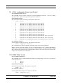
ATX;&V;+GSN;+CMEE=?;+CPBR=1,12;-MSVTR?
(semicolon separators)
ATX&V+GSN+CMEE=?+CPBR=1,12-MSVTR?
(no separators)
3.6
Command Responses
A result code is sent to the DTE in response to the execution of a command. It may also occur unsolicited
from other conditions such as an incoming call (e.g., RING). Responses returned as a result of a query are
called information responses.
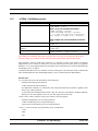
Result codes can be represented by text if the ISU is in verbose mode or with numbers if in numeric mode.
The command ATVn informs the ISU whether to respond in verbose or numeric mode. Further note that
responses can be suppressed with by setting the command ATQn to ATQ1. Table 3-1 below shows the
difference in format between these modes.
Table 3-1: Result Code Response Format
Result codes
Information Responses
Numeric Mode
Verbose Mode
ATQ0 ATV0
ATQ0 ATV1
<NUMERIC_CODE><CR> <CR><LF><VERBOSE_CODE><CR><LF>
<TEXT><CR><LF>
<CR><LF><TEXT><CR><LF>
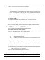
Command entries with invalid syntax typically respond with ERROR. Command entries of valid syntax
with an out-of-range parameter can respond in one of three following manners:
Disallow out-of-range entry and respond with ERROR
Disallow out-of-range entry and respond with OK
Disallow out-of-range entry, accept the closest in-range value, and respond with OK
Iridium Proprietary
20 June 2011
Version 2.45
10
ISU AT Command Reference
Phased Implementation by Software Release
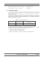
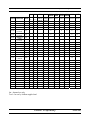
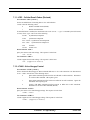
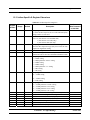
4 Phased Implementation by Software Release
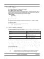
The AT commands described in this document have been implemented into various ISU models in a phased software
release approach, building on previous implementations. The Phase I AT Commands have been implemented in all ISU
models. The Phase II, III, IV, V, VI and VII AT Commands have been implemented in other ISU models as shown in
Table 4-1 below.
Note that some AT commands select operation that is dependent on Iridium network service capability.
Table 4-1: Phased AT Command Implementation
Software Release
Phase I
Phase II
Phase III
Phase IV
Phase V
Phase VI
ISU Model AT Commands AT Commands AT Commands AT Commands AT Commands AT Commands
INC0620
Not implemented Not implemented Not implemented Not implemented Not implemented
9500
RAC0620
Not implemented Not implemented Not implemented Not implemented Not implemented
9520
9521
9505
9522
9505A
9522A
9555
9522B
Phase VII
AT Commands
Not implemented
Not implemented
Not implemented
LAC109G
Not implemented Not implemented Not implemented Not implemented Not implemented
Not implemented Not implemented
LAC109G
LAC03xx
LAC03xx
SAC0201
SAC0201
SAC0201
SAC03xx
Not implemented Not implemented
Not implemented
All versions
All versions
All versions
All versions
RAC0620
All versions
All versions
All versions
All versions
Not implemented
Not implemented
IS060xx
Not implemented
All versions
IS060xx
Not implemented
All versions
All versions
All versions
All versions unless
otherwise specified
All versions
All versions
All versions
All versions
All versions
All versions
All versions
All versions
All versions
All versions
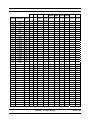
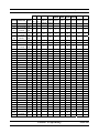
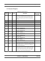
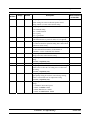
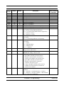
Table 4-2 below and on the following three pages details the implementation of individual AT commands.
Table 4-2: Phased AT Command Implementation – Command Detail
9505 9522 9505A 9522A
Section Command Phase
5.1
5.2
5.3
5.4
5.5
5.6
5.7
5.7.1
5.8
5.9
5.10
5.11
5.12
5.13
5.14
AT
A/
+++
A (initial)
Bn
Cn
D (initial)
D> (initial)
En
Fn
Hn (initial)
In
Ln
Mn
Nn
I
I
I
I
I
I
I
I
I
I
I
I
I
I
I
9505A 9505A 9505A 9505A
9555 9522B
9522A 9522A 9522A 9522A
MDAxxxx MDAxxxx
LAC03 SAC03
MDBxxxx MDBxxxx IS060xx IS07001 IS08001 IS090xx HT090xx ST0900x
xx
xx
IS0500x IS0500x
X
X
X
X
X
X
X
X
X
X
X
X
X
X
X
X
X
X
X
X
X
X
X
X
X
X
X
X
X
X
X
X
X
X
X
X
X
X
X
X
X
X
X
X
X
X
X
X
X
X
X
X
X
X
X
X
X
X
X
X
X
X
X
X
X
X
X
X
X
X
X
X
X
X
X
X
X
X
X
X
X
X
X
X
X
X
X
X
X
X
X
X
X
X
X
X
X
X
X
X
X
X
X
X
X
X
X
X
X
X
Iridium Proprietary
20 June 2011
Version 2.45
11
ISU AT Command Reference
Phased Implementation by Software Release
9505 9522 9505A 9522A
Section Command Phase
5.15
5.16
5.17
5.18
5.19
5.20
5.21
5.22
5.23
5.24
5.25
5.26
5.27
5.28
5.29
5.30
5.31
5.32
5.33
5.34
5.35
5.36
5.37
5.38
5.39
5.40
5.41
5.42
5.43
5.44
5.45
5.46
5.47
5.48
5.49
5.50
5.51
5.52
5.53
5.54
5.55
5.56
On
P
Qn
S0=n (initial)
T
Vn
Wn
Xn (initial)
Yn
Zn
&Cn
&Dn (initial)
&Fn
&Gn
&Jn
&Kn
&Ln
&Mn
&Pn
&Qn
&Rn
&Sn
&V
&Wn
&Xn
&Yn
\An
\Bn
\Gn
\Jn
\Kn
\Nn
%Cn
%En
%R
*Pn
+CBST
+CGMI
+CGMM
+CGMR
+CGSN
+CMEE
I
I
I
I
I
I
I
I
I
I
I
I
I
I
I
I
I
I
I
I
I
I
I
I
I
I
I
I
I
I
I
I
I
I
I
I
I
I
I
I
I
I
9505A 9505A 9505A 9505A
9555 9522B
9522A 9522A 9522A 9522A
MDAxxxx MDAxxxx
LAC03 SAC03
MDBxxxx MDBxxxx IS060xx IS07001 IS08001 IS090xx HT090xx ST0900x
xx
xx
IS0500x IS0500x
X
X
X
X
X
X
X
X
X
X
X
X
X
X
X
X
X
X
X
X
X
X
X
X
X
X
X
X
X
X
X
X
X
X
X
X
X
X
X
X
X
X
X
X
X
X
X
X
X
X
X
X
X
X
X
X
X
X
X
X
X
X
X
X
X
X
X
X
X
X
X
X
X
X
X
X
X
X
X
X
X
X
X
X
X
X
X
X
X
X
X
X
X
X
X
X
X
X
X
X
X
X
X
X
X
X
X
X
X
X
X
X
X
X
X
X
X
X
X
X
X
X
X
X
X
X
X
X
X
X
X
X
X
X
X
X
X
X
X
X
X
X
X
X
X
X
X
X
X
X
X
X
X
X
X
X
X
X
X
X
X
X
X
X
X
X
X
X
X
X
X
X
X
X
X
X
X
X
X
X
X
X
X
X
X
X
X
X
X
X
X
X
X
X
X
X
X
X
X
X
X
X
X
X
X
X
X
X
X
X
X
X
X
X
X
X
X
X
X
X
X
X
X
X
X
X
X
X
X
X
X
X
X
X
X
X
X
X
X
X
X
X
X
X
X
X
X
X
X
X
X
X
X
X
X
X
X
X
X
X
X
X
X
X
X
X
X
X
X
X
X
X
X
X
X
X
X
X
X
X
X
X
X
X
X
X
X
X
X
X
X
X
X
X
X
X
X
X
X
X
X
X
X
X
X
X
X
X
X
X
X
X
X
X
X
X
X
X
X
X
X
X
X
X
X
X
X
X
X
X
X
X
X
X
X
X
X
X
X
X
X
X
X
X
X
X
X
X
X
X
X
X
X
X
X
X
X
X
X
X
X
X
X
X
X
X
X
X
X
X
X
X
X
X
X
X
X
X
X
X
X
X
X
X
X
X
X
X
X
X
Iridium Proprietary
20 June 2011
Version 2.45
12
ISU AT Command Reference
Phased Implementation by Software Release
9505 9522 9505A 9522A
Section Command Phase
5.57
5.58
5.59
5.60
5.61
5.62
6.1
6.2
6.3
6.4
6.5
6.6
6.7
6.8
6.9
6.10
6.11
6.12
6.13
6.14
6.15
6.16
6.17
6.18
6.19
6.20
6.21
6.22
6.23
6.24
6.25
6.26
6.27
6.28
6.29
6.30
6.31
7.1
7.2
7.2.1
7.3
7.4
+CPAS
+CR
+CRC(initial)
+DS
+DR
+IPR
+CBC(initial)
+CEER
+CHUP
+CLCK
+CMGD
+CMGF
+CMGL
+CMGR
+CMGS
+CMGW
+CMOD
+CNMI
+COPS
+CPBF
+CPBR
+CPBS
+CPBW
+CPIN
+CPMS
+CPWD
+CREG
+CSCA
+CSCB
+CSCS
+CSMS
+CSTA
+GMI
+GMM
+GMR
+GSN
+GCAP
A (revised)
D (revised)
D> (revised)
Hn (revised)
S0=n
I
I
I
I
I
I
II
II
II
II
II
II
II
II
II
II
II
II
II
II
II
II
II
II
II
II
II
II
II
II
II
II
II
II
II
II
II
III
III
III
III
III
9505A 9505A 9505A 9505A
9555 9522B
9522A 9522A 9522A 9522A
MDAxxxx MDAxxxx
LAC03 SAC03
MDBxxxx MDBxxxx IS060xx IS07001 IS08001 IS090xx HT090xx ST0900x
xx
xx
IS0500x IS0500x
X
X
X
X
X
X
X
X
X
X
X
X
X
X
X
X
X
X
X
X
X
X
X
X
X
X
X
X
X
X
X
X
X
X
X
X
X
X
X
X
X
X
X
X
X
X
X
X
X
X
X
X
X
X
X
X
X
X
X
X
X
X
X
X
X
X
X
X
X
X
X
X
X
X
X
X
X
X
X
X
X
X
X
X
X
X
X
X
X
X
X
X
X
X
X
X
X
X
X
X
X
X
X
X
X
X
X
X
X
X
X
X
X
X
X
X
X
X
X
X
X
X
X
X
X
X
X
X
X
X
X
X
X
X
X
X
X
X
X
X
X
X
X
X
X
X
X
X
X
X
X
X
X
X
X
X
X
X
X
X
X
X
X
X
X
X
X
X
X
X
X
X
X
X
X
X
X
X
X
X
X
X
X
X
X
X
X
X
X
X
X
X
X
X
X
X
X
X
X
X
X
X
X
X
X
X
X
X
X
X
X
X
X
X
X
X
X
X
X
X
X
X
X
X
X
X
X
X
X
X
X
X
X
X
X
X
X
X
X
X
X
X
X
X
X
X
X
X
X
X
X
X
X
X
X
X
X
X
X
X
X
X
X
X
X
X
X
X
X
X
X
X
X
X
X
X
X
X
X
X
X
X
X
X
X
X
X
X
X
X
X
X
X
X
X
X
X
X
X
X
X
X
X
X
X
X
X
X
X
X
X
X
X
X
X
X
X
X
X
X
X
X
X
X
X
X
X
X
X
X
X
X
X
X
X
X
X
X
X
X
X
X
X
X
X
X
X
X
X
X
X
X
X
X
X
X
X
X
X
X
X
X
X
X
X
X
X
X
X
X
X
X
X
X
X
X
X
X
X
X
X
X
X
X
X
X
X
X
X
X
X
X
X
X
Iridium Proprietary
20 June 2011
Version 2.45
13
ISU AT Command Reference
Phased Implementation by Software Release
9505 9522 9505A 9522A
Section Command Phase
7.5
7.6
7.7
7.8
7.9
7.10
7.11
7.12
7.13
7.14
7.15
7.16
7.17
8.1
8.2
8.3
8.4
8.5
8.6
8.7
8.8
8.9
8.10
8.11
8.12
8.13
8.14
8.15
8.16
8.17
8.18
9.1
10.1
10.2
10.3
10.4
10.5
(revised)
Xn (revised)
&Dn
(revised)
+CBC
(revised)
+CSQ
(initial)
+CLVL
+CMUT
+CRC
(revised)
+CVHU
+CCLK
-MSVTS
-MSVTR
-MSVLS
-MSSTM
-MSGEO
+CCFC
+CLCC
+CNUM
+WIRLP
+WFRNG
+WTM
+WDLDM
+WDAV
+SBDWB
+SBDRB
+SBDWT
+SBDRT
+SBDI
+SBDD
+SBDC
+SBDS
+SBDTC
+CAR
I (revised)
+CIER
+CRIS
+CSQ
(revised)
+CULK
9505A 9505A 9505A 9505A
9555 9522B
9522A 9522A 9522A 9522A
MDAxxxx MDAxxxx
LAC03 SAC03
MDBxxxx MDBxxxx IS060xx IS07001 IS08001 IS090xx HT090xx ST0900x
xx
xx
IS0500x IS0500x
III
X
X
X
X
X
X
X
X
X
X
III
X
X
X
X
X
X
X
X
X
X
III
X
X
X
X
X
X
X
X
X
X
III
III
III
X
X
X
X
X
X
X
X
X
X
X
X
X
X
X
X
X
X
X
X
X
X
X
X
X
X
X
X
X
X
III
III
III
III
III
III
III
IV
IV
IV
IV
IV
IV
IV
IV
IV
IV
IV
IV
IV
IV
IV
IV
IV
IV
V
VI
VI
VI
X
X
X
X
X
X
X
X
X
X
X
X
X
X
X
X
X
X
X
X
X
X
X
X
X
X
X
X
X
X
X
X
X
X
X
X
X
X
X
X
X
X
X
X
X
X
X
X
X
X
X
X
X
X
X
X
X
X
X
X
X
X
X
X
X
X
X
X
X
X
X
X
X
X
X
X
X
X
X
X
X
X
X
X
X
X
X
X
X
X
X
X
X
X
X
X
X
X
X
X
X
X
X
X
X
X
X
X
X
X
X
X
X
X
X
X
X
X
X
X
X
X
X
X
X
X
X
X
X
X
X
X
X
X
X
X
X
X
X
X
X
X
X
X
X
X
X
X
X
X
X
X
X
X
X
X
X
X
X
X
X
X
X
X
X
X
X
X
X
X
X
X
X
X
X
X
X
X
X
X
X
X
X
X
X
X
X
X
X
X
X
X
X
X
X
X
X
X
X
X
X
X
X
X
X
X
X
X
X
X
X
X
X
X
X
X
X
X
X
X
X
X
X
X
X
X
X
X
X
X
X
X
X
X
X
X
X
X
X
X
X
X
X
X
X
X
X
X
X
X
X
X
X
X
X
X
X
X
X
X
X
X
X
X
X
X
X
X
X
X
X
X
X
X
VI
X
X
X
X
X
X
VI
X
X
X
X
X
X
Iridium Proprietary
20 June 2011
Version 2.45
14
ISU AT Command Reference
Phased Implementation by Software Release
9505 9522 9505A 9522A
Section Command Phase
10.6
10.7
10.8
10.9
10.10
10.11
10.12
10.13
10.14
10.15
10.16
10.17
10.18
10.19
11.1
11.2
+CVMI
+CICCID
+CLIP
+CLIR
+IPR
(revised)
+SBDWT
(revised)
+SBDDET
+SBDI
(revised)
+SBDIX
+SBDDSC
+SBDMTA
+SBDREG
+SBDAREG
+SBDSX
+ADJANT
+WANTST
+ANTST
+PCDA
+DPLCI
+CCWA
+CLCK
+CPWD
+CSDT
+CHLD
+XCSI
11.3
11.4
11.5
11.6
11.7
11.8
11.9
11.10
11.11 +FEATURES
11.12 +FWVER
11.13 +LFWVER
11.14
+CDSI
11.15
+KEY
11.16
+CKPD
VI
VI
VI
9505A 9505A 9505A 9505A
9555 9522B
9522A 9522A 9522A 9522A
MDAxxxx MDAxxxx
LAC03 SAC03
MDBxxxx MDBxxxx IS060xx IS07001 IS08001 IS090xx HT090xx ST0900x
xx
xx
IS0500x IS0500x
X
X
X
X
X
X
X
X
X
X
X
X
X
X
X
X
X
X
X
VI
X
X
X
X
X
X
VI
X
X
X
X
X
X
VI
X
X
X
X
X
X
VI
X
X
X
X
X
X
VI
VI
VI
VI
VI
VI
VII
X
X
X
X
X
X
X
X
X
X
X
X
X
X
X
X
X
X
X
X
X
X
X
X
X
X
X
X
X
X
X
X
X
X
X
X
Int
VII
Int
VII
VII
VII
VII
VII
VII
VII
VII
VII
VII
VII
VII
VII
VII
Int
Int
X
X
X
X
X
X
X
X
X
X
X
X
Int
Tool
Tool
Tool
Int
X
X
Int = Internal use only
Tool = for use by Iridium supplied tool
Iridium Proprietary
20 June 2011
Version 2.45
15
ISU AT Command Reference
Phase I AT Commands
5 Phase I AT Commands
5.1
AT - ATtention Code
This is the prefix for all commands except A/ and +++. When entered on its own, the ISU will respond
OK.
5.2
A/ - Repeat Last Command
Repeat the last command issued to the ISU unless the power was interrupted or the unit is reset. A/ is not
followed by <CR>.
5.3
+++ - Escape Sequence
The escape sequence is used to transfer from in-call data mode to in-call command mode without
disconnecting from the remote modem. After a pause, the ISU will respond with OK. Register S2 can be
used to alter the escape character from +, the factory default, to any hexadecimal value in the range 0 to
255.
5.4
A - Answer (Initial implementation; revised in Phase III)
Answer immediately. This causes the ISU to answer the incoming data call.
5.5
Bn - Communication Standards
Select the communications standard to be used for data calls.
No action, compatibility only.
Any value for n accepted.
5.6
Cn - Carrier Control
Control carrier detection.
No action, compatibility only.
Only n=1 accepted.
Iridium Proprietary
20 June 2011
Version 2.45
16
ISU AT Command Reference
5.7
Phase I AT Commands
D - Dial (Initial implementation; revised in Phase III)
Dial a data call number. The dial command causes the ISU to enter originate mode and act as an auto
dialer for connection to other modems. The usual format is ATDnx..x where n is a Dial Modifier and x is
a number. The following are valid numbers: 0123456789*#ABC. Dial modifiers are used to alter the
manner in which the ISU dials.
L
Redial last number.
P
Use pulse dialing.
No action, compatibility only.
T
Use tone dialing.
No action, compatibility only.
+
International dialing prefix. Allows the international access code to be omitted from dial
string.
>
Direct dial from phonebook locations. See subsection below for further details.
Direct dial from phonebook not implemented in models 9500 with INC0620, 9520 with
RAC0620, or 9521 with RAC0620 .
Any character received from the DTE during the call establishment phase will cause the call attempted to
be terminated.
5.7.1
Direct Dial From Phonebook (Initial implementation; revised in Phase III)
The ISU and SIM contain phonebooks which have a phone number and an alphanumeric field for each
phonebook entry location. The use of V.25ter dialing command ensures that direct dialing from phone
memory and SIM phonebook is possible through ordinary communications software which just gives the
phone number field to be filled and then use the D command to originate the call. Available memories may
be queried with Select Phonebook Storage test command +CPBS=?, and location range for example with
Read Phonebook Entries test command +CPBR=?.
Execute commands:
D><str>
Originate call to phone number which corresponding alphanumeric field is <str> (if possible, all available
memories should be searched for the correct entry). <str> is of string type value and should enclosed by ““
(e.g., “John”).
D> mem<n>
Originate call to phone number in memory mem entry location <n> (available memories may be queried
with Select Phonebook Storage test command +CPBS=?).
mem can be one of the following:
FD
SIM fixed dialing phonebook
LD
Last ten calls dialed phonebook
ME
Phone memory
MT
Combined phone and SIM phonebook locations
SM
SIM phonebook
D><n>
Originate call to phone number in entry location <n> (the command Select Phonebook Memory Storage
+CPBS setting determines which phonebook storage is used).
Iridium Proprietary
20 June 2011
Version 2.45
17
ISU AT Command Reference
5.8
Phase I AT Commands
En - Echo
Echo command characters.
5.9
0
Characters are not echoed to the DTE.
1
Characters are echoed to the DTE (default).
Fn - Line Modulation
Select line modulation standard.
No action, compatibility only.
Allowed values for n are 0, 1, 3, 4, 5, 6, 7, 8, 9 and 10.
5.10 Hn - Hangup (Initial implementation; revised in Phase III)
Control the hook switch. This command is used to clear a data call connection.
0
Place the ISU on hook.
5.11 In – Identification (Initial implemenation; revised in Phase VI)
Requests the ISU to display information about itself.
0
“2400” (traffic channel rate for IRIDIUM data/fax)
1
“0000” (ROM checksum which is not supported so zero is output)
2
“OK” (result of ROM checksum verification which is not supported so OK is always output)
3
“XXXXXXXX” (Software revision level)
4
“IRIDIUM” (Product description)
5
“XXXX” (country code)
6
“XXXXXXXX” (Hardware specification)
5.12 Ln - Loudspeaker Volume
Set the loudspeaker volume according to the parameter supplied.
No action, compatibility only.
Allowed values for n are 0, 1, 2 and 3.
5.13 Mn - Speaker Control
Select when the speaker will be on or off. Note that serially connected products have no speaker.
No action, compatibility only.
Allowed values for n are 0, 1, 2 and 3.
Iridium Proprietary
20 June 2011
Version 2.45
18
ISU AT Command Reference
Phase I AT Commands
5.14 Nn - Automode Enable
Enable or disable automode detection.
No action, compatibility only.
Any value for n is accepted.
5.15 On - Online
Enter in-call data mode. This is used to return to in-call data mode from in-call command mode using an
existing connection. An error is reported if on-hook.
0
Switch from in-call command mode to in-call data mode.
Any value for n accepted.
5.16 P - Pulse Dial
Set pulse dial.
No action, compatibility only.
5.17 Qn - Quiet Mode
Control ISU responses.
0
ISU responses are sent to the DTE (default).
1
ISU responses are NOT sent to the DTE.
5.18 S0=n - Auto-Answer (Initial implementation; revised in Phase III)
Auto-answer. This causes the ISU to auto-answer the incoming data call.
0
Disable auto-answer.
n>0
Enable auto-answer.
5.19 T - Tone Dial
Set tone dial.
No action, compatibility only.
Iridium Proprietary
20 June 2011
Version 2.45
19
ISU AT Command Reference
Phase I AT Commands
5.20 Vn - Verbose Mode
Set the response format of the ISU, which may be either numeric or textual.
0
Numeric responses.
1
Textual responses (default).
5.21 Wn - Error Correction Message Control
Set the format of the CONNECT messages.
0
Upon connection, the ISU reports the DTE speed (default).
1
Upon connection, the ISU reports the line speed, the error correction protocol and the DTE
speed in that order.
2
Upon connection, the ISU reports the DCE speed.
5.22 Xn - Extended Result Codes (Initial implementation; revised in Phase III)
Select the response set to be used by the ISU when informing the DTE of the results of a command or data
call.
0
OK, CONNECT, RING, NO CARRIER, NO ANSWER and ERROR.
1
As X0 plus CONNECT x, where x is the DTE speed.
2
As X1 plus NO DIALTONE.
3
As X2 plus BUSY.
4
As X3 plus CARRIER x, PROTOCOL: and COMPRESSION:, where x is the line speed
(default).
Notes:
1) The Wn command limits which connection related responses will be reported.
2) The CONNECT response is used to inform of a data call connection; OK response is used to
inform of a voice call connection.
3) DAV connections start out as a voice call and will produce an OK response followed by a
CONNECT response when the call automatically transitions to data mode.
5.23 Yn - Long Space Disconnect
Enable or disable the generation and response to long space disconnect.
No action, compatibility only.
Any value for n is accepted.
5.24 Zn - Soft Reset
Reset the ISU to a user-stored configuration.
0
Restores user configuration 0.
1
Restores user configuration 1.
Iridium Proprietary
20 June 2011
Version 2.45
20
ISU AT Command Reference
Phase I AT Commands
5.25 &Cn - DCD Option
Select how the ISU controls the DCD behavior.
0
DCD is forced on at all times.
1
DCD indicates the connection status (default).
5.26 &Dn - DTR Option (Initial implementation; revised in Phase III)
Set the ISU reaction to DTR signal.
DTR must be ON during on-hook command mode. If DTR transitions from ON to OFF during on-hook
command mode, operation will be locked after approximately 10 seconds. On-hook command mode
operation will resume when DTR is restored ON.
DTR must be ON at call connection.
DTR must be ON during both in-call command mode and in-call data mode. Reaction to DTR ON to OFF
transitions during in-call command mode and in-call data mode is determined by the &Dn setting as shown
below.
0
If DTR transitions from ON to OFF during in-call command mode, and DTR is restored ON
within approximately 10 seconds, the call will remain up. If DTR is not restored ON within
approximately 10 seconds, the call will drop to on-hook command mode.
If DTR transitions from ON to OFF during in-call data mode, the mode will remain in in-call
data mode. If DTR is restored ON within approximately 10 seconds, the call will remain up.
If DTR is not restored ON within approximately 10 seconds, the call will drop to on-hook
command mode.
1
If DTR transitions from ON to OFF during in-call command mode, and DTR is restored ON
within approximately 10 seconds, the call will remain up. If DTR is not restored ON within
approximately 10 seconds, the call will drop to on-hook command mode.
If DTR transitions from ON to OFF during in-call data mode, the mode will change to in-call
command mode. If DTR is restored ON within approximately 10 seconds, the call will
remain up. If DTR is not restored ON within approximately 10 seconds, the call will drop to
on-hook command mode.
2
If DTR transitions from ON to OFF during either in-call command mode or in-call data mode,
the call will drop to on-hook command mode (default).
3
If DTR transitions from ON to OFF during either in-call command mode or in-call data mode,
the call will drop to on-hook command mode and the ISU will reset to AT command profile 0.
5.27 &Fn - Restore Factory Settings
Recall factory defaults.
0
Recall factory default 0.
5.28 &Gn - Guard Tone
Select guard tone.
No action, compatibility only.
Iridium Proprietary
20 June 2011
Version 2.45
21
ISU AT Command Reference
Phase I AT Commands
Any value for n is accepted.
5.29 &Jn - Jack Control
Control the telephone jack configuration.
No action, compatibility only.
Allowed values for n are 0 and 1.
5.30 &Kn - Flow Control
Select the flow control method between the ISU and DTE.
0
Disables flow control.
3
Enables RTS/CTS flow control (default).
4
Enables XON/XOFF flow control.
6
Enables both RTS/CTS and XON/XOFF flow control.
5.31 &Ln - Leased Line Operation
Request leased line or dial-up operation.
No action, compatibility only.
Any value for n is accepted.
5.32 &Mn - Asynchronous/Synchronous Mode
Select the DTR operating mode.
0
Selects normal asynchronous operation (default). (See &Q0.)
5.33 &Pn - Pulse Dial Make/Break Ratio
Select the make/break ratio during pulse dialing.
No action, compatibility only.
Allowed values for n are 0, 1, 2 and 3.
5.34 &Qn - Sync/Async Mode
Select asynchronous mode. This is an extension of the &M command and is used to control the connection
modes permitted.
Note: The register is not updated right after the user requests new values because the requested values may
or may not be what IRLP will use once a data call is established due to negotiations with the other peer. If
the register is updated right away, this may give the user the impression that those values will be used
during the data call, but there is no guarantee that will be the case. The real values will only be known once
a data call is established and the negotiation phase is done. For that reason, the values are written to the
register only after a call is established and both sides have negotiated parameter values (such as mode of
operation). The value of the register will be reset to default value (5) after the call completed.
Iridium Proprietary
20 June 2011
Version 2.45
22
ISU AT Command Reference
Phase I AT Commands
0, 6
Normal asynchronous operation with no error correction (unacknowledged mode). .
5
Asynchronous
operation
with
error
correction
Iridium Proprietary
20 June 2011
(acknowledged
mode)
(default)
Version 2.45
23
ISU AT Command Reference
Phase I AT Commands
5.35 &Rn - RTS/CTS Option
Select how the ISU controls CTS.
No action, compatibility only.
Allowed values for n are 0 and 1.
5.36 &Sn - DSR Override
Define the behavior of DSR.
0
DSR always active (default).
1
Same as 0.
5.37 &V - View Active and Stored Configuration
View the current active configuration and stored profiles.
5.38 &Wn - Store Active Configuration
Store the active profile in non-volatile memory. This is used to store user configurations for later use.
0
Store current (active) configuration as profile 0.
1
Store current (active) configuration as profile 1.
5.39 &Xn - Select Synchronous Clock
Select the source of the transmit clock for synchronous mode of operation.
No action, compatibility only.
Any value for n is accepted.
5.40 &Yn - Designate Default Reset Profile
Select profile for use after power-up.
0
Select profile 0 (default).
1
Select profile 1.
5.41 \An - MNP Block Size
Select maximum MNP block size.
No action, compatibility only.
Iridium Proprietary
20 June 2011
Version 2.45
24
ISU AT Command Reference
Phase I AT Commands
5.42 \Bn - Transmit Break
Transmit break to remote. In non-error correction mode, the ISU will transmit a break signal to the remote
modem with a length in multiples of 100 ms according to the parameter specified. Values for n is 1-9.
No action, compatibility only.
5.43 \Gn - XON/XOFF Flow Control
Set the use of XON/XOFF flow control in normal mode.
No action, compatibility only.
5.44 \Jn - DTE Auto Rate
Enable DTE auto rate adjustment
No action, compatibility only.
5.45 \Kn - Control Break
Control the response of the ISU to a break received from the DTE or the remote modem according to the
parameter specified. The response is different in three separate states:
When a break is received from DTE when ISU is in data transfer mode:
0
Enter in-call command mode, no break sent to remote modem.
1
Clear data buffers and send break to remote modem.
2
Same as 0.
3
Send break to remote modem immediately.
4
Same as 0.
5
Send break to remote modem in sequence with transmitted data (default).
When a break is received from the remote modem during a non-error corrected connection:
0
Clear data buffers and send break to DTE.
1
Same as 0.
2
Send break to DTE immediately.
3
Same as 2.
4
Send break to DTE in sequence with received data.
5
Same as 4 (default).
5.46 \Nn - Link Type
Define the link type to be used.
No action, compatibility only.
Iridium Proprietary
20 June 2011
Version 2.45
25
ISU AT Command Reference
Phase I AT Commands
5.47 %Cn - Compression Control
Enable/disable data compression. Data compression can only be performed on an error corrected link (i.e.,
acknowledged mode).
No action, compatibility only. Use the +DS command to set data compression.
5.48 %En - Auto Retrain
Enable/disable auto retrain.
No action, compatibility only.
Allowed values for n are 0, 1 and 2.
5.49 %R - Display Registers
Display all the S registers in the system.
5.50 *Pn - Power Phone
Turn ISU off.
0
Turn phone OFF.
This command is not supported on the 9555 and 9555A Handsets.
Iridium Proprietary
20 June 2011
Version 2.45
26
ISU AT Command Reference
Phase I AT Commands
5.51 +CBST - Select Bearer Service Type
Set Command: +CBST=[<speed>[,<name>[,<ce>]]]
Select the bearer service type for mobile originated calls.
<speed> can have the following values:
0
Autobauding
1
300 bps V.21
2
1200 bps V.22
4
2400 bps V.22bis
6
4800 bps V.32
7
9600 bps V.32 (default)
65
300 bps V.110
66
1200 bps V.110
68
2400 bps V.110
70
4800 bps V.110
71
9600 bps V.110
<name> takes the following value:
0
data circuit asynchronous
<ce> can only take the following value:
1
non-transparent
Read Command: +CBST?
Query the current bearer service type settings. Response is in the form:
+CBST: <speed>,<name>,<ce>
Test Command: +CBST=?
List the supported <speed>, <name>, <ce>. Response is in the form:
+CBST: (supported <speed>s),(supported <name>s),(supported <ce>s)
5.52 +CGMI - Manufacturer Identification
Exec Command: +CGMI
Query phone manufacturer.
5.53 +CGMM - Model Identification
Exec Command: +CGMM
Query phone model.
This command does not support command concatenation in the 9555 and 9555A Handsets.
Iridium Proprietary
20 June 2011
Version 2.45
27
ISU AT Command Reference
Phase I AT Commands
5.54 +CGMR - Revision
Exec Command: +CGMR
Query the phone revision.
5.55 +CGSN - Serial Number
Exec Command: +CGSN
Query the phone IMEI.
5.56 +CMEE - Report Mobile Equipment Error
Set Command: +CMEE=[<x>]
Set mobile equipment error reporting level.
<x> takes the following values:
0
Disable error reporting (use ERROR result code) (default).
1
Enable numeric error reporting.
2
Enable verbose error reporting.
An example of an error report is:
+CME ERROR: <y>
where <y> can be the number or text listed below:
0
phone failure
1
no connection to phone
2
phone-adaptor link reserved
3
operation not allowed
4
operation not supported
5
PH-SIM PIN required
6
PH-FSIM PIN required
7
PH-FSIM PUK required
10
SIM not inserted
11
SIM PIN required
12
SIM PUK required
13
SIM failure
14
SIM busy
15
SIM wrong
16
incorrect password
17
SIM PIN2 required
18
SIM PUK2 required
20
memory full
21
invalid index
22
not found
Iridium Proprietary
20 June 2011
Version 2.45
28
ISU AT Command Reference
Phase I AT Commands
23
memory failure
24
text string too long
25
invalid characters in text string
26
dial string too long
27
invalid characters in dial string
28
number is SIM fixed dialling restricted
30
no network service
31
network timeout
32
emergency calls only
40
network personalization PIN required
41
network personalization PUK required
42
network subset personalization PIN required
43
network subset personalization PUK required
44
service provider personalization PIN required
45
service provider personalization PUK required
46
corporate personalization PIN required
47
corporate personalization PUK required
100
unknown
146
GPS Settings Lock PIN required (9575 only)
Read Command: +CMEE?
Query mobile equipment error reporting level. The response is in the form:
+CMEE: <x>
Test Command: +CMEE=?
List the supported error reporting level. The response is in the form:
+CMEE: (supported <x>s)
5.57 +CPAS - Phone Activity Status
Exec Command: +CPAS
Query phone activity status. The response is in the form:
+CPAS: <x>
where <x> can take the following values:
0
Ready (allows commands).
1
Unavailable (does not allow commands).
2
Unknown (may not respond to commands).
3
Data Call Ringing (allows commands).
4
Data Call In Progress (allows commands).
Models 9500 with INC0620, 9520 with RAC0620, and 9521 with RAC0620 return
from status 4 to status 3 at the end of a data call. They subsequently return to status
0 after reset or power cycle.
Iridium Proprietary
20 June 2011
Version 2.45
29
ISU AT Command Reference
Phase I AT Commands
5.58 +CR - Service Reporting Control
Set Command: +CR=[<mode>]
Set the service reporting level.
<mode> takes the following values:
0
Disable reporting (default).
1
Enable reporting.
If reporting is enabled, the intermediate result code +CR: <serv> is returned by the ISU.
<serv> can have one of the following values:
ASYNC
asynchronous transparent
SYNC
synchronous transparent
REL ASYNC asynchronous non-transparent
REL SYNC
synchronous non-transparent
Read Command: +CR?
Query the current service reporting level settings. The response is in the form:
+CR: <mode>
Test Command: +CR=?
List the supported reporting levels. The response is in the form:
+CR: (supported <mode>s)
5.59 +CRC - Cellular Result Codes (Initial implementation; revised in Phase III)
Set Command: +CRC=[<mode>]
Set the extended format of incoming data call indication.
<mode> takes the following values:
0
Disable extended format (default).
1
Enable extended format.
If extended format is enabled, the unsolicited result code +CRING: <type> is returned by the ISU instead
of RING, where <type> can be one of the following:
ASYNC
asynchronous transparent
SYNC
synchronous transparent
REL ASYNC asynchronous non-transparent
REL SYNC
synchronous non-transparent
Read Command: +CRC?
Query the current result code settings. The response is in the form:
+CR: <mode>
Test Command: +CRC=?
List the supported result code settings. The response is in the form:
+CR: (supported <mode>s)
Iridium Proprietary
20 June 2011
Version 2.45
30
ISU AT Command Reference
Phase I AT Commands
5.60 +DS - Set Data Compression Function
Set Command: +DS=[<direction>[,<comp_neg>[,<max_dict>[,<max_string]]]]
Set the V.42bis data compression function.
<direction> can take on the following values:
0
No compression
1
Transmit only
2
Receive only
3
Both directions (default)
<comp_neg> can take on the following values:
0
Do not disconnect if V.42bis is not negotiated by the remote DCE as specified in
<direction> (default)
1
Disconnect if V.42bis is not negotiated by the remote DCE as specified in <direction>
<max_dict> can take on the following values: 512 to 2048. Default is 512.
<max_string> can take on the following values: 6 to 250. Default is 6.
Read Command: +DS?
Query the current data compression parameter settings. The response is in the form:
+DS: <direction>,<comp_neg>,<max_dict>,<max_dict>
Test Command: +DS=?
List the supported data compression parameters. The response is in the form:
+DS: (supported <direction>s),(supported <comp_neg>s,(supported
<max_dict>s),(supported <max_dict>s)
Data compression will not work if IRLP is in unacknowledged mode.
Note: The register is not updated right after the user requests new values because the requested values may
or may not be what IRLP will use once a data call is established due to negotiations with the other peer. If
the register is updated right away, this may give the user the impression that those values will be used
during the data call, but there is no guarantee that will be the case. The real values will only be known once
a data call is established and the negotiation phase is done. For that reason, the values are written to the
register only after a call is established and both sides have negotiated parameter values. The value of the
register will be reset to default value (3) after the call completed.
5.61 +DR - Data Compression Report Level
Set Command: +DR=[<mode>]
Set the data compression reporting level.
<mode> can take on the following values:
0
Disable data compression reporting (default)
1
Enable data compression reporting
If reporting is enabled, the following intermediate result codes are transmitted by the ISU:
+DR: NONE
No data compression.
+DR: V42B
Data compression in use in both directions.
+DR: V42B RD
Data compression in use in receive direction only.
Iridium Proprietary
20 June 2011
Version 2.45
31
ISU AT Command Reference
Phase I AT Commands
Data compression in use in transmit direction only.
+DR: V42B TD
Read Command: +DR?
Query the current reporting level setting. The response is in the form:
+DR: <mode>
Test Command: +DR=?
List the supported parameter settings. The response is in the form:
+DR: (supported <mode>s)
5.62 +IPR - Fixed DTE Rate (Initial implementation; revised in Phase VI)
Note: ISU models 9505 and 9522 will automatically adjust to changes in the DTE rate and override the
+IPR setting when dissimilar.
Set Command: +IPR=<rate>[,<autobaud>]
Set the data rate at which the ISU will accept commands. The change in data rate takes into effect after the
result code (e.g., OK) is received by the DTE.
<rate> takes the following values:
1
600 bps
2
1200 bps
3
2400 bps
4
4800 bps
5
9600 bps
6
19200 bps (default)
7
38400 bps
Note: The use of 38400 bps with ISU models “9505” or “9522” is not recommended because the ISU can
not handle this rate without losing some bits of data.
<autobaud> takes the following values:
0
disable autobaud
1
enable autobaud
Read Command: +IPR?
Query the current data rate. The response is in the form:
+IPR: <rate>
Test Command: +IPR=?
List the supported data rates. The response is in the form:
+IPR: (supported <rate>s)
Iridium Proprietary
20 June 2011
Version 2.45
32
ISU AT Command Reference
Phase II AT Commands
6 Phase II AT Commands
6.1
+CBC - Battery Charge (Initial implementation; revised in Phase III)
Exec Command: +CBC
Execution command returns the battery connection status <bcs> and battery charge level <bcl> of the
phone. The response is in the form:
+CBC: <bcs>,<bcl>
where <bcs>:
000
ISU is powered by the battery.
001
ISU has a battery connected, but is not powered by it.
002
ISU does not have a battery connected.
003
Recognized power fault, calls inhibited.
and <bcl>:
000
Battery is exhausted, or ISU does not have a battery connected.
001...100 Battery has 1-100 percent of capacity remaining.
Test Command: +CBC=?
Test command returns the values for <bcs> and <bcl> supported by the ISU. Response is in the form:
+CBC: (list of supported <bcs>s),(list of supported <bcl>s)
6.2
+CEER - Extended Error Report
Exec Command: +CEER
Execution command causes the phone to return information text <report> which offers the user an extended
report of the reason of the failure in the last unsuccessful call setup (originating or answering) or the reason
for last call release. The response is in the form:
+CEER: <report>
An example of a <report> is:
User alerting, no answer
6.3
+CHUP - Hangup call
This command causes the phone to hangup the current data or voice call. If hungup in this manner then the
incoming call will not be forwarded to voice-mail. To allow a rejected call to be forwarded to voice-mail
(if configured) used ATH0 instead.
Iridium Proprietary
20 June 2011
Version 2.45
33
ISU AT Command Reference
6.4
Phase II AT Commands
+CLCK - Facility Lock (Phase II version)
See also section 11.6 for the 9555/9522B extensions to this command.
Exec Command: +CLCK=<fac>,<mode>,<passwd>
Execute command is used to activate or deactivate the SIM card PIN Code, or to enable or disable the
Phone Lock feature in the ISU. The current SIM card PIN Code or Phone Unlock Code is required to
perform these actions.
Note:
This command will not work unless the SIM PIN has been entered using the +CPIN command.
Note:
Once this command has been issued to disable the PIN, neither it nor the +CPIN need to be issued again
unless the PIN function is reactivated.
The following parameter values are currently supported:
<fac>:
“CS”
CNTRL Surface (Enable/Disable Phone Lock feature)
“SC”
SIM (Activate/Deactivate SIM card PIN Code)
<mode>:
0
Disable (Deactivate)
1
Enable (Activate)
<passwd>: string type, enclosed by “ “; for example, “1234”.
Note: Factory default SIM card PIN Code is “1111”
Note: Factory default Phone Unlock Code is “1234”
Test Command: +CLCK=?
Test command returns the facility values supported by the phone. The response is in the form:
+CLCK: (list of supported <fac>s)
Note: Only “CS” will appear as a supported value if there is no SIM card in the device.
Note: +CLCK is closely related to +CPIN and +CPWD. See these commands for additional information.
6.5
+CMGD - Delete SMS Message
Exec Command: +CMGD=<index>
Execution command deletes message from preferred message storage <mem1> (<mem1> is the selected
message storage from the +CPMS command) location <index>. If deleting fails, final result code +CMS
ERROR: <cms_err> is returned.
An example of an error report is:
+CMS ERROR: <cms_err>
where <cms_err> can be one of the numbers below:
1
unassigned number
Iridium Proprietary
20 June 2011
Version 2.45
34
ISU AT Command Reference
Phase II AT Commands
8
operator barred
3
operation not allowed (identical to 302)
10
call barred
21
SM transfer rejected
27
destination out of service
28
unidentified subscriber
29
facility rejected
30
unknown subscriber
38
network out of order
41
temporary failure
42
congestion
47
resources unavailable
50
facility not subscribed
69
facility not implemented
81
invalid SM reference value
95
invalid message
96
invalid mandatory information element
97
nonexistent message type
98
incompatible message
99
nonexistent information element
111
protocol error
127
interworking
128
telephony interworking not supported
129
SM type 0 not supported
130
cannot replace SM
143
unspecified TP-PID error
144
coding scheme not supported
145
message class not supported
159
unspecified TP-DCS error
160
command not actioned
161
command unsupported
176
TPDU not supported
192
SC busy
193
no SC subscription
194
SC system failure
195
invalid SME address
196
destination SME barred
197
SM rejected
208
SIM SMS storage full
Iridium Proprietary
20 June 2011
Version 2.45
35
ISU AT Command Reference
6.6
Phase II AT Commands
209
no SMS storage capability in SIM
210
error in MS
211
memory capacity exceeded
255
unspecified error
300
phone failure
301
SMS service reserved
302
operation not allowed
303
operation not supported
304
invalid PDU mode parameter
305
invalid text mode parameter
310
no SIM
311
SIM PIN required
312
PH-SIM PIN required
313
SIM failure
314
SIM busy
315
SIM wrong
320
memory failure
321
invalid memory index
322
memory full
330
SM-SC address unknown
331
no network service
332
network timeout
500
unknown error
+CMGF - SMS Message Format
Set Command: +CMGF=[<mode>]
Set command tells the phone, which input and output format of messages to use. <mode> indicates the format of messages used with send, list, read and write commands and unsolicited result codes resulting from
received messages. Mode can be either PDU mode (entire TP data units used) or text mode (headers and
body of the messages given as separate parameters). Only PDU mode is supported at this time.
Valid values for <mode> are:
0
PDU mode (default)
Read Command: +CMGF?
Read command returns the current <mode> set. Response is in the form:
+CMGF: <mode>
Test Command: +CMGF=?
Test command returns the list of supported <mode>s. Response is in the form:
+CMGF: (list of supported <mode>s)
Iridium Proprietary
20 June 2011
Version 2.45
36
ISU AT Command Reference
6.7
Phase II AT Commands
+CMGL - List SMS Messages
Exec Command: +CMGL[=<stat>]
Execution command returns messages with status value <stat> from message storage <mem1> (<mem1> is
the selected message storage from the +CPMS command) to the DTE. If listing fails, final result code
+CMS ERROR: <cms_err> is returned.
Valid values for <stat> are:
PDU
Text
0
"REC UNREAD"
received unread message (i.e. new message) (default)
1
"REC READ"
received read message
2
"STO UNSENT"
stored unsent message (only applicable to SMs)
3
"STO SENT"
stored sent message (only applicable to SMs)
4
"ALL" all messages (only applicable to +CMGL command)
Response is in the following format for PDU mode:
+CMGL:
<index>,<stat>,[<alpha>],<length><CR><LF><pdu>
[<CR><LF>+CMGL:<index>,<stat>,[<alpha>],<length><CR><LF><pdu> [...]]
where:
<alpha>: string type alphanumeric representation of TP-destination address or TP-originating
address corresponding to the entry found in the phonebook (optional field);
<length>: in PDU mode, this is the length of the actual TP data unit in octets (i.e. the RP layer
SMSC address octets are not counted in the length)
<pdu>: GSM 04.11 SC address followed by GSM 03.40 TPDU in hexadecimal format.
Test Command: +CMGL=?
Test command gives a list of all status values supported by the phone. Response is in the form:
+CMGL: (list of supported <stat>s)
6.8
+CMGR - Read SMS Message
Exec Command: +CMGR=<index>
Execution command returns the SMS message with location value <index> from message storage <mem1>
(<mem1> is the selected message storage from the +CPMS command). If status of the message is
’received unread’, status in the storage changes to ’received read’. If reading fails, final result code +CMS
ERROR: <cms_err> is returned.
Response is in the following format for PDU mode:
+CMGR: <stat>,[<alpha>],<length><CR><LF><pdu>
where:
<stat>:
0 - MT message unread
1 - MT message read
2 - MO message unsent
3 - MO message sent
(When reading an MT message the first time, the status is reported as 0 (unread). The status is
Iridium Proprietary
20 June 2011
Version 2.45
37
ISU AT Command Reference
Phase II AT Commands
then changed to 1 (read), and that is reported on subsequent reads of that
message.)
<alpha>: string type alphanumeric representation of TP-destination address or TP-originating
address corresponding to the entry found in the phonebook (optional field);
<length>: in PDU mode, this is the length of the actual TP data unit in octets (i.e. the RP layer
SMSC address octets are not counted in the length)
<pdu>: GSM 04.11 SC address followed by GSM 03.40 TPDU in hexadecimal format.
6.9
+CMGS - Send SMS Message
Exec Command: +CMGS=<length><CR><pdu><ctrl-Z/ESC> (PDU mode)
Execution command sends message from a DTE to the network (SMS-SUBMIT). In PDU mode, <length>
is the length of the actual TP data unit in octets; <pdu> is the GSM 04.11 SC address followed by GSM
03.40 TPDU in hexadecimal format.
PDU entry must be terminated by <ctrl-Z>. Sending can be cancelled by the <ESC> character.
Response is in the following format for PDU mode:
+CMGS: <mr>
where <mr> is the message reference value of the message.
If sending fails, final result code +CMS ERROR: <cms_err> is returned.
6.10 +CMGW - Write SMS Message To Memory
Exec Command: +CMGW=<length>[,<stat>]<CR><pdu><ctrl-Z/ESC> (PDU mode)
Execution command stores a message to memory storage <mem2> (<mem2> is selected by the +CPMS
command). In PDU mode, <length> is the length of the actual TP data unit in octets; <pdu> is the GSM
04.11 SC address followed by GSM 03.40 TPDU in hexadecimal format. By default, message status will
be set to ’stored unsent’, but parameter <stat> allows also other status values to be given.
PDU entry must be terminated by <ctrl-Z>. Storing can be cancelled by sending the <ESC> character.
Response is in the following format for PDU mode:
+CMGW: <index>
where <index> indicates the memory location where the message is stored.
If storing fails, final result code +CMS ERROR: <cms_err> is returned.
6.11 +CMOD - Call Mode
Set Command: +CMOD=[<mode>]
Set command selects the call mode of further dialing commands (D) or for next answering command (A).
Mode can be either single or alternating (the terms "alternating mode" and "alternating call" refer to all
GSM bearer and teleservices that incorporate more than one basic service (voice, data, fax) within one
call). For the satellite phones, only a single call is supported.
<mode>:
0
single mode (default)
Read Command: +CMOD?
Query the current call mode settings. The response is in the form:
Iridium Proprietary
20 June 2011
Version 2.45
38
ISU AT Command Reference
Phase II AT Commands
+CMOD: <mode>
Test Command: +CMOD=?
List the supported call modes. The response is in the form:
+CMOD: (supported <mode>s)
Iridium Proprietary
20 June 2011
Version 2.45
39
ISU AT Command Reference
Phase II AT Commands
6.12 +CNMI - New SMS Message Indications to DTE
Set Command: +CNMI=[<mode>[,<mt>[,<bm>[,<ds>[, <bfr>]]]]]
Set command selects the procedure, how receiving of new messages from the network is indicated to the
DTE when DTE is active, e.g. DTR signal is ON.
Valid values for <mode> are:
0
Buffer unsolicited result codes in the phone. If result code buffer is full, older indications are discarded and replaced with the new received indications. (default)
1
Discard indication and reject new received message unsolicited result codes when ISUDTE link is reserved (e.g. in in-call data mode). Otherwise forward them directly to
the DTE.
2
Buffer unsolicited result codes in the phone when ISU-DTE link is reserved (e.g. in incall data mode) and flush them to the DTE after reservation. Otherwise forward them
directly to the DTE.
Valid values for <mt> are:
0
No SMS-DELIVER indications are routed to the DTE. (default)
1
If SMS-DELIVER is stored in the phone, indication of the memory location is routed
to the DTE using unsolicited result code:
+CMTI: <mem>,<index>
2
SMS-DELIVERs (except class 2 messages and messages in the message waiting
indication group (store message)) are routed directly to the TE using unsolicited result
code:
+CMT: [<alpha>],<length><CR><LF><pdu> (PDU mode)
3
Class 3 SMS-DELIVERs are routed directly to TE using unsolicited result codes
defined in <mt>=2. Messages of other data coding schemes result in indication as
defined in <mt>=1.
Valid values for <bm> are:
0
No CBM indications are routed to the DTE. (default)
Valid values for <ds> are:
0
No SMS-STATUS-REPORTs are routed to the DTE. (default)
1
SMS-STATUS-REPORTs are routed to the DTE using unsolicited result code:
+CDS: <length><CR><LF><pdu> (PDU mode)
Valid values for <bfr> are:
0
Buffer of unsolicited result codes defined within this command is flushed to the DTE
when <mode> 1...3 is entered (OK response is returned before flushing the codes).
(default)
1
Buffer of unsolicited result codes defined within this command is cleared when
<mode> 1...3 is entered.
Iridium Proprietary
20 June 2011
Version 2.45
40
ISU AT Command Reference
Phase II AT Commands
Read Command: +CNMI?
Read command returns the current settings for the SMS message indication. Response is in the form:
+CNMI: <mode>,<mt>,<bm>,<ds>,<bfr>
Test Command: +CNMI=?
Test command returns the supported settings of the phone. Response is in the form:
+CNMI: (list of supported <mode>s),(list of supported <mt>s),(list
of supported <bm>s),(list of supported <ds>s),(list of supported <bfr>s)
6.13 +COPS - Operator Select
Set Command: +COPS=[<mode>[,<format>[,<oper>]]]
Set command forces an attempt to manually register the phone to the network. Only IRIDIUM as <oper>
is supported.
Valid values for the parameters are outlined below.
<mode>:
0
automatic (<oper> field is ignored) (default)
1
manual (<oper> field is optional)
<format>:
0
long format alphanumeric <oper>
1
short format alphanumeric <oper>
2
numeric <oper>
<oper> is of string type enclosed by quotes“”; for example “IRIDIUM”. <format> indicates if the format is
alphanumeric or numeric; long alphanumeric format can be up to 16 characters long and short format up to
8 characters; numeric format is the Location Area Identification number which consists of a three BCD
(Binary Coded Decimal) digit country code plus a two BCD digit network code; hence the number has
structure: (country code digit 3)(country code digit 2)(country code digit 1)(network code digit 2)(network
code digit 1). Since IRIDIUM is the only operator, the short and long format is “IRIDIUM” and the
numeric format is “90103”. These are the only values accepted.
Note that setting the <mode> to manual does not disable automatic registration of the phone to the network.
It just forces a manual registration procedure when entered.
Read Command: +COPS?
Read command returns the current mode, and will always respond with as “000” for <mode>. This is due
to the continually enabled nature of the automatic registration mode. The response is in the form:
+COPS: <mode>
For example:
+COPS:000
Iridium Proprietary
20 June 2011
Version 2.45
41
ISU AT Command Reference
Phase II AT Commands
Test Command: +COPS=?
Test command returns the list of operators present in the network. Response is in the form:
+COPS: [list of supported (<stat>,long alphanumeric <oper>,short
alphanumeric <oper>,numeric <oper>)s] [,,(list of supported
<mode>s),(list of supported <format>s)]
where <stat> indicates:
2
current
For example:
+COPS:(002),"IRIDIUM","IRIDIUM","90103",,(000-001),(000-002)
6.14 +CPBF - Find phonebook entries
Exec Command: +CPBF=<findtext>
Execution command returns phonebook entries (from the current phonebook memory storage selected with
+CPBS) which alphanumeric field start with string <findtext>. <findtext> should of string type enclosed
by ““; for example, “John”.
Entry fields returned are location number <index n>, phone number stored there <number> (of address type
<type>), and text <text> associated with the number. Response is in the following format:
+CPBF:
<index1>,<number>,<type>,<text>[[...]<CR><LF>+CBPF:
<index2>,<number>,<type>,<text>]
Test Command: +CPBF=?
Test command returns the maximum lengths of <number> and <text> fields for phonebook entries.
Response is in the form:
+CPBF: <nlength>,<tlength>
where <nlength> indicates the maximum length of <number> and <tlength> shows the maximum length of
<text>.
6.15 +CPBR - Read phonebook entries
Exec Command: +CPBR=<index1>[,<index2>]
Execution command returns phonebook entries in location number range <index1>... <index2> from the
current phonebook memory storage selected with +CPBS. If <index2> is left out, only location <index1>
is returned.
Entry fields returned are location number <index n>, phone number stored there <number> (of address type
<type>) and text <text> associated with the number. Response is in the form:
+CPBR:
<index1>,<number>,<type>,<text>[[...]
<CR><LF>+CPBR:
<index2>,<number>,<type>,<text>]
Test Command: +CPBR=?
Test command returns location range supported by the current storage and the maximum lengths of <number> and <text> fields. Response is in the form:
+CPBR: (list of supported <index>s),<nlength>,<tlength>
where <nlength> indicates the maximum length of <number> and <tlength> shows the maximum length of
<text>.
Iridium Proprietary
20 June 2011
Version 2.45
42
ISU AT Command Reference
Phase II AT Commands
6.16 +CPBS - Select phonebook storage
Set Command: +CPBS=<storage>
Set command selects phonebook memory storage <storage>, which is used by other phonebook commands.
<storage> should be of string type enclosed by “”; for example, “FD”.
<storage> takes the following values:
FD
SIM fixed dialing phonebook
LD
Last ten calls dialed phonebook
ME
ISU phonebook
MT
combined ISU and SIM phonebook (default)
SM
SIM phonebook
Read Command: +CPBS?
Read command returns currently selected memory, the number of used locations and total number of locations in the memory. Response is in the form:
+CPBS: <storage>,<used>,<total>
where <used> indicates the number of used locations and <total> shows the total capacity of <storage>.
Test Command: +CPBS=?
Test command returns supported storages.
6.17 +CPBW - Write phonebook entry
Exec Command: +CPBW=[<index>][,<number>[,<type>[<text>]]]
Execution command writes phonebook entry in location number <index> in the current phonebook
memory storage selected with +CPBS. Entry fields written are phone number <number> (of address type
<type>) and text <text> associated with the number. If those fields are omitted, phonebook entry is
deleted. If <index> is left out, but <number> is given, entry is written to the first free location in the
phonebook. Both <text> and <number> should be of string type enclosed by ““; for example,
“John”,”1234”.
Test Command: +CPBW=?
Test command returns the location range supported by the current storage, the maximum length of <number> field, supported number formats of the storage, and the maximum length of <text> field. Response is
in form:
+CPBW: (list of supported <index>s),<nlength>,(list of supported
<type>s),<tlength>
Iridium Proprietary
20 June 2011
Version 2.45
43
ISU AT Command Reference
Phase II AT Commands
6.18 +CPIN - Enter PIN
Set Command: +CPIN=<pin>[,<newpin>]
Set command sends to the phone a password which is necessary before it can be operated (SIM Card PIN
Code, SIM PUK, etc.). If no password request is pending, no action is taken by the phone.
If the password required is SIM PUK, then <newpin> is required, where <newpin> is the new
SIM Card PIN to replace the old SIM Card PIN.
If the password required is SIM PUK2, then <newpin> is required, where <newpin> is the
new SIM Card PIN2 to replace the old SIM Card PIN2
Both <pin> and <newpin> should be of string type enclosed by “ “; for example,”1234”.
Read Command: +CPIN?
Read command returns an alphanumeric string indicating whether some password is required or not.
Response is in the form:
+CPIN: <code>
where <code> can be one of the following:
READY
ISU is not waiting for any password.
PH PIN
ISU is waiting for Phone Unlock Code to be given.
SIM PIN
ISU is waiting for SIM Card PIN1 Code to be given.
SIM PUK
ISU is waiting for SIM PUK to be given (because SIM PIN1 is blocked).
SIM PIN2
ISU is waiting for SIM PIN2 to be given.*
SIM PUK2
ISU is waiting for SIM PUK2 to be given (because SIM PIN2 is blocked).
*Note: The response “SIM PIN2” is somewhat misleading, because it indicates one of three
possible scenarios:
1) PIN1 has already been successfully entered (thus equivalent to the READY response).
2) No PIN1 is required (thus equivalent to the READY response).
3) The phone is waiting for PIN2 (used to access Fixed Dialing settings and other subscriptionbased features).
In any of these three cases, the phone should be available to place and receive calls.
Note: +CPIN is closely related to +CLCK and +CPWD. See these commands for additional information.
Iridium Proprietary
20 June 2011
Version 2.45
44
ISU AT Command Reference
Phase II AT Commands
6.19 +CPMS - Select Preferred SMS Message Storage
Set Command: +CPMS=<mem1>[, <mem2>[,<mem3>]]
Set command selects memory storages <mem1>, <mem2> and <mem3>. <mem1> is the memory from
which messages are read and deleted; <mem2> is the memory to which writing and sending operations are
made; <mem3> is the memory to which received SMS messages are to be stored. If a chosen storage is not
appropriate for the phone, final result code +CMS ERROR: <cms_err> is returned.
Valid values for <mem1>, <mem2> and <mem3> are:
"SM"
SIM message storage
Response is in the form:
+CPMS: <used1>,<total1>,<used2>,<total2>,<used3>,<total3>
where <used1>: number of messages currently in <mem1>
<total1>: total number of message locations in <mem1>
<used2>: number of messages currently in <mem2>
<total2>: total number of message locations in <mem2>
<used3>: number of messages currently in <mem3>
<total3>: total number of message locations in <mem3>
Read Command: +CPMS?
Read command returns the current storage selected, usage and capacity. Response is in the form:
+CPMS:
<mem1>,<used1>,<total1>,<mem2>,<used2>,<total2>,
<mem3>,<used3>,<total3>
Test Command: +CPMS=?
Test command returns lists of memory storages supported by the phone. Response is in the form:
+CPMS: (list of supported <mem1>s),(list of supported <mem2>s),
(list of supported <mem3>s)
6.20 +CPWD - Change Password (Phase II version)
See also section 11.7 for the 9555/9522B extensions to this command.
Exec Command: +CPWD=<fac>,<oldpwd>,<newpwd>
This command sets a new password for the facility lock function defined by the AT command Facility
Lock +CLCK . The following parameter values are currently supported:
<fac>:
“CS”
CNTRL Surface (Phone Unlock Code)
“SC”
SIM (SIM Card PIN Code)
“P2”
SIM PIN2 (SIM Card PIN2 Code)
Note: AT+CPWD=”SC”,<oldpwd>,<newpwd> will return “Error” unless the SIM Card Pin Code is
currently activated (see AT command Facility Lock +CLCK).
Iridium Proprietary
20 June 2011
Version 2.45
45
ISU AT Command Reference
Phase II AT Commands
Test Command: +CPWD=?
Test command returns a list of pairs which present the available facilities and the maximum length of their
password. Response is in the form:
+CPWD: list of supported (<fac>,<pwdlength>)s
where <pwdlength> indicates the maximum length for the password.
Note: +CPWD is closely related to +CLCK and +CPIN. See these commands for additional information.
6.21 +CREG - Network Registration
Set Command: +CREG=[<n>]
Set command controls the presentation of an unsolicited result code +CREG: <stat> when <n>=1 and
there is a change in the ISU network registration status, or code +CREG: <stat>[,<lac>,<ci>]
when <n>=2 and there is a change in the registration status of the phone.
Valid values for <n> are:
0
disable network registration unsolicited result code (default)
1
enable network registration unsolicited result code +CREG: <stat>
2
enable network registration and location information unsolicited result code +CREG:
<stat>[,<lac>,<ci>]. <lac> indicates the location area code in string format;
<ci> is in the cell identifier which is not applicable to IRIDIUM.
<stat> can be one of the following:
0
not registered, ISU is not currently searching a new operator to register to
1
registered, home network
2
not registered, but ISU is currently searching a new operator to register to
3
registration denied
4
unknown
5
registered, roaming
Read Command: +CREG?
Read command returns the status of result code presentation and an integer <stat> which shows whether the
network registration status of the phone. Location information elements <lac> and <ci> are returned only
when <n>=2 and phone is registered in the network. Response is in the form:
+CREG: <n>,<stat>[,<lac>,<ci>]
Test Command: +CREG=?
Test command lists the supported settings for +CREG. Response is in the form:
+CREG: (list of supported <n>s)
Iridium Proprietary
20 June 2011
Version 2.45
46
ISU AT Command Reference
Phase II AT Commands
6.22 +CSCA - SMS Service Center Address
Set Command: +CSCA=<sca>[,<tosca>]
Set command updates the SMSC address, through which mobile originated SMs are transmitted. In PDU
mode, setting is used by the send and write commands, but only when the length of the SMSC address
coded into <pdu> parameter equals zero.
<sca>: GSM 04.11 RP SC address Address-Value field in string format (i.e., enclosed by quotes ““);
<tosca>: GSM 04.11 RP SC address Type-of-Address octet in integer format;
Read Command: +CSCA?
Read command returns the current service center address. Response is in the form:
+CSCA: <sca>,<tosca>
6.23 +CSCB - Select Cell Broadcast Message Types
Set Command: +CSCB=[<mode>[,<mids>[,<dcss>]]]
Set command selects which types of CBMs are to be received by the ME.
No action, compatibility only.
Read Command: +CSCB?
Read command returns the current values for <mode>, <mids> and <dcss>. Response is in the form:
+CSCB: <mode>,<mids>,<dcss>
Test Command: +CSCB=?
Test command returns supported modes. Response is in the form:
+CSCB: (list of supported <mode>s)
6.24 +CSCS - Select TE Character Set
Set Command: +CSCS=[<chset>]
Set command informs the phone which character set <chset> is used by the DTE. Only the IRA character
set is currently supported. <chset> should be of string type enclosed by ““; for example, “IRA”.
Valid values for <chset> are:
"IRA"
international reference alphabet (ITU-T T.50)
Read Command: +CSCS?
Read command returns the current character set used. Response is in the form:
+CSCS: <chset>
Test Command: +CSCS=?
Test command returns the supported character set of the phone. Response is in the form:
+CSCS: (list of supported <chset>s)
Iridium Proprietary
20 June 2011
Version 2.45
47
ISU AT Command Reference
Phase II AT Commands
6.25 +CSMS - Select SMS Message Service
Set Command: +CSMS=<service>
Set command selects short messaging service <service>. It returns the types of messages supported by the
phone: <mt> for mobile terminated messages, <mo> for mobile originated messages and <bm> for broadcast type messages. If chosen service is not supported, final result code +CMS ERROR: <cms_err> shall
be returned. Only message service type 0 is currently supported.
Valid values for <service> are:
0
GSM 03.40 and 03.41 (the syntax of SMS AT commands is compatible with GSM
07.05 Phase 2 version 4.7.0) (default)
Response is in the form:
+CSMS: <mt>,<mo>,<bm>
where, <mt>, <mo>, <bm>:
0
type not supported
1
type supported
Read Command: +CSMS?
Read command returns the current message service type set. Response is in the form:
+CSMS: <service>,<mt>,<mo>,<bm>
Test Command: +CSMS=?
Test command returns the supported message services of the phone. Response is in the form:
+CSMS: (list of supported <service>s)
6.26 +CSTA - Select Type of Address
Set Command: +CSTA=[<type>]
Select the type of number for the dial command D. <type> is the type of address in integer format specified
in GSM 4.08 subclause 10.5.4.7. Typical values for <type> are:
129
Unknown type (default)
145
International number.
Read Command: +CSTA?
Query the current address type settings. The response is in the form:
+CSTA: <type>
Test Command: +CSTA=?
List the supported address type settings. The response is in the form:
+CSTA: (supported <type>s)
6.27 +GMI - Manufacturer Identification
Exec Command: +GMI
Query phone manufacturer. This command is similar to +CGMI.
Iridium Proprietary
20 June 2011
Version 2.45
48
ISU AT Command Reference
Phase II AT Commands
6.28 +GMM - Model Identification
Exec Command: +GMM
Query phone model. This command is similar to +CGMM.
This command does not support command concatenation in the 9555 and 9555A Handsets.
6.29 +GMR - Revision
Exec Command: +GMR
Query the phone revision. This command is similar to +CGMR.
6.30 +GSN - Serial Number
Exec Command: +GSN
Query the phone IMEI. This command is similar to +CGSN.
6.31 +GCAP - General Capabilities
Exec Command: +GCAP
Query the phone’s overall capabilities.
Iridium Proprietary
20 June 2011
Version 2.45
49
ISU AT Command Reference
Phase III AT Commands
7 Phase III AT Commands
7.1
A - Answer (Revised)
Answer immediately. This causes the ISU to answer the incoming data or voice call.
7.2
D - Dial (Revised)
Dial a data or voice call number. The dial command causes the ISU to enter originate mode and act as an
auto dialer for connection to other modems or voice lines. The usual format is ATDnx..x where n is a Dial
Modifier and x is a number. The following are valid numbers: 0123456789*#ABC. Dial modifiers are
used to alter the manner in which the ISU dials.
L
Redial last number.
P
Use pulse dialing.
No action, compatibility only.
T
Use tone dialing.
No action, compatibility only.
+
International dialing prefix. Allows the international access code to be omitted from dial
string.
>
Direct dial from phonebook locations. See subsection below for further details.
;
Start up a voice call. This modifier should be given after the dialing digits (or modifiers).
Any character received from the DTE during the call establishment phase will cause the call attempted to
be terminated.
Iridium Proprietary
20 June 2011
Version 2.45
50
ISU AT Command Reference
7.2.1
Phase III AT Commands
Direct Dial From Phonebook (Revised)
The ISU and SIM contain phonebooks which have a phone number and an alphanumeric field for each
phonebook entry location. The use of V.25ter dialing command ensures that direct dialing from phone
memory and SIM phonebook is possible through ordinary communications software which just gives the
phone number field to be filled and then use the D command to originate the call. Available memories may
be queried with Select Phonebook Storage test command +CPBS=?, and location range for example with
Read Phonebook Entries test command +CPBR=?.
Execute commands:
D><str>[;]
Originate call to phone number which corresponding alphanumeric field is <str> (if possible, all available
memories should be searched for the correct entry). <str> is of string type value and should enclosed by ““
(e.g., “John”).
D> mem<n>[;]
Originate call to phone number in memory mem entry location <n> (available memories may be queried
with Select Phonebook Storage test command +CPBS=?).
mem can be one of the following:
FD
SIM fixed dialing phonebook
LD
Last ten calls dialed phonebook
ME
Phone memory
MT
combined phone and SIM phonebook locations
SM
SIM phonebook
D><n>[;]
Originate call to phone number in entry location <n> (the command Select Phonebook Memory Storage
+CPBS setting determines which phonebook storage is used).
7.3
Hn - Hangup (Revised)
Control the hook switch. This command is used to clear a data call connection. It is also used to clear a
voice call connection when the ISU has originated the voice call with the ATD dial command or terminated
the voice call with the ATA or ATS0=n answer command.
0
7.4
Place the ISU on hook.
S0=n - Auto-Answer (Revised)
Auto-answer. This causes the ISU to auto-answer the incoming data or voice call.
0
Disable auto-answer.
n>0
Enable auto-answer after n rings
Iridium Proprietary
20 June 2011
Version 2.45
51
ISU AT Command Reference
7.5
Phase III AT Commands
Xn - Extended Result Codes (Revised)
Select the response set to be used by the ISU when informing the DTE of the results of a command or data
or voice call.
0
OK, CONNECT, RING, NO CARRIER, NO ANSWER and ERROR.
CONNECT response is used to inform of a data call connection; OK response is used to
inform of a voice call connection.
1
As X0 plus CONNECT x, where x is the DTE speed.
CONNECT x response is used for data calls only.
2
As X1 plus NO DIALTONE.
3
As X2 plus BUSY.
4
As X3 plus CARRIER x, PROTOCOL: and COMPRESSION:, where x is the line speed
(default).
CARRIER x, PROTOCOL:, and COMPRESSION: responses are used for data calls
only.
Note that the Wn command limits which connection related responses will be reported.
7.6
&Dn - DTR Option (Revised)
Set the ISU reaction to DTR signal.
0
DTR is ignored in all modes. A DTR signal input is not needed when set to &D0.
For all other &Dn settings, the following applies.
DTR must be ON during on-hook command mode. If DTR transitions from ON to OFF during on-hook
command mode, operation will be locked after approximately 10 seconds. On-hook command mode
operation will resume when DTR is restored ON.
DTR must be ON at call connection
DTR must be ON during both in-call command mode and in-call data mode. Reaction to DTR ON to OFF
transitions during in-call command mode and in-call data mode is determined by the &Dn setting as shown
below. Note that the +CVHU command can be set to override these specified reactions.
1
If DTR transitions from ON to OFF during in-call command mode, and DTR is restored ON
within approximately 10 seconds, the call will remain up. If DTR is not restored ON within
approximately 10 seconds, the call will drop to on-hook command mode.
If DTR transitions from ON to OFF during in-call data mode, the mode will change to in-call
command mode. If DTR is restored ON within approximately 10 seconds, the call will
remain up. If DTR is not restored ON within approximately 10 seconds, the call will drop to
on-hook command mode.
2
If DTR transitions from ON to OFF during either in-call command mode or in-call data mode,
the call will drop to on-hook command mode (default).
3
If DTR transitions from ON to OFF during either in-call command mode or in-call data mode,
the call will drop to on-hook command mode and the ISU will reset to AT command profile 0.
Iridium Proprietary
20 June 2011
Version 2.45
52
ISU AT Command Reference
7.7
Phase III AT Commands
+CBC - Battery Charge (Revised)
Exec Command: +CBC
Execution command returns the battery connection status <bcs> and battery charge level <bcl> of the
phone. On 9555 and 9555A Handsets, the charger connection status <ccs> and the battery accumulator
level <bal> is also returned. The response is in the form:
+CBC: <bcs>,<bcl>[,<ccs>,<bal>]
where <bcs>:
000
ISU is powered by the battery.
001
ISU has a battery connected, but is not powered by it.
002
ISU does not have a battery connected.
003
Recognized power fault, calls inhibited.
and <bcl>:
000
Equivalent to 0 bars displayed on the ISU battery charge indicator, or ISU does not
have a battery connected.
001
Equivalent to 1 bar displayed on the ISU battery charge indicator.
002
Equivalent to 2 bars displayed on the ISU battery charge indicator.
003
Equivalent to 3 bars displayed on the ISU battery charge indicator.
004
Handsets only).
Equivalent to 4 bars displayed on the ISU battery charge indicator (on 9555 and 9555A
and <ccs>:
001
Charger connected and charging
002
Charger connected, not charging
003
Charger not connected
and <bal>:
xxx
Integer from 000 to 100 indicating percentage charge from accumulator reading
Test Command: +CBC=?
Test command returns the values for <bcs> and <bcl> supported by the ISU. On 9555 and 9555A
Handsets, also returns the values for <ccs> and <bal> supported by the ISU. Response is in the form:
+CBC: (list of supported <bcs>s),(list of supported <bcl>s)[
,(list of supported <ccs>s),(list of supported <bal>s) ]
This command does not support command concatenation on the 9555 and 9555A Handsets.
Iridium Proprietary
20 June 2011
Version 2.45
53
ISU AT Command Reference
7.8
Phase III AT Commands
+CSQ - Signal Quality (Initial implementation; revised in Phase VI)
Exec Command: +CSQ
Execution command returns the received signal strength indication <rssi> from the ISU. Response is in the
form:
+CSQ: <rssi>
where <rssi> is:
0
Equivalent to 0 bars displayed on the ISU signal strength indicator.
1
Equivalent to 1 bar displayed on the ISU signal strength indicator.
2
Equivalent to 2 bars displayed on the ISU signal strength indicator.
3
Equivalent to 3 bars displayed on the ISU signal strength indicator.
4
Equivalent to 4 bars displayed on the ISU signal strength indicator.
5
Equivalent to 5 bars displayed on the ISU signal strength indicator.
Test Command: +CSQ=?
List the supported signal strength indications. The response is in the form:
+CSQ: (supported <rssi>s)
Note: A signal strength response may not be immediately available, but will usually be received within
two seconds of issuing the command. If the ISU is in the process of acquiring the system or in a satellite
handoff, a delay in response of up to 10 seconds may be experienced.
If the ISU has no SIM, is awaiting a SIM PIN entry, has an invalid SIM, or has otherwise not proceeded to
successful registration, the delay in response may exceed the 50 second timeout limit. Under such
condition, an ERROR response will be received. To avoid a delayed response due to registration problems,
issue the +CREG command to verify registration prior to entering the +CSQ command to obtain signal
strength.
Iridium Proprietary
20 June 2011
Version 2.45
54
ISU AT Command Reference
7.9
Phase III AT Commands
+CLVL - Loudspeaker Volume Level Control
Exec Command: +CLVL=<level>
This command is used to select the volume of the internal loudspeaker of the ISU. <level> is an integer
type value with the smallest value representing the lowest sound level.
Read Command: +CLVL?
Query the current volume level settings. The response is in the form:
+CLVL: <level>
0
Equivalent to level 0 displayed on the ISU volume indicator.
1
Equivalent to level 1 displayed on the ISU volume indicator.
2
Equivalent to level 2 displayed on the ISU volume indicator.
3
Equivalent to level 3 displayed on the ISU volume indicator.
4
Equivalent to level 4 displayed on the ISU volume indicator.
5
Equivalent to level 5 displayed on the ISU volume indicator.
6
Equivalent to level 6 displayed on the ISU volume indicator.
7
Equivalent to level 7 displayed on the ISU volume indicator.
8
Equivalent to level 8 displayed on the ISU volume indicator. [9555 / 9555A only]
9
Equivalent to level 9 displayed on the ISU volume indicator. [9555 / 9555A only]
10
Equivalent to level 10 displayed on the ISU volume indicator. [9555 / 9555A only]
Test Command: +CLVL=?
List the supported volume level settings. The response is in the form:
+CLVL: (supported <level>s)
This command does not support command concatenation on the 9555 and 9555A Handsets.
Note: In the 9555 and 9555A Handsets, the range of supported volume levels is different depending on
whether audio is routed to analog or digital (using AT+CAR command). The supported range for digital
audio is 000-007, the supported range for analog audio is 000-010. The correct range for the current audio
routing will be returned by the test command.
7.10 +CMUT - Mute Control
Exec Command: +CMUT=<n>
This command is used to enable and disable the uplink voice muting during a voice call. <n> can take one
of the following values:
0
mute off
1
mute on
Read Command: +CMUT?
Query the current mute setting. The response is in the form:
+CMUT: <n>
Test Command: +CMUT=?
List the supported mute settings. The response is in the form:
+CMUT: (supported <n>s)
Iridium Proprietary
20 June 2011
Version 2.45
55
ISU AT Command Reference
Phase III AT Commands
This command does not support command concatenation on the 9555 and 9555A Handsets.
Iridium Proprietary
20 June 2011
Version 2.45
56
ISU AT Command Reference
Phase III AT Commands
7.11 +CRC - Cellular Result Codes (Revised)
Set Command: +CRC=[<mode>]
Set the extended format of incoming data or voice call indication.
<mode> takes the following values:
0
Disable extended format (default).
1
Enable extended format.
If extended format is enabled, the unsolicited result code +CRING: <type> is returned by the ISU instead
of RING, where <type> can be one of the following:
ASYNC
asynchronous transparent
SYNC
synchronous transparent
REL ASYNC asynchronous non-transparent
REL SYNC
synchronous non-transparent
FAX
facsimile
VOICE
normal voice
Read Command: +CRC?
Query the current result code settings. The response is in the form:
+CR: <mode>
Test Command: +CRC=?
List the supported result code settings. The response is in the form:
+CR: (supported <mode>s)
7.12 +CVHU - Voice Hangup Control
Set Command: +CVHU=[<mode>]
Selects whether the Hn (hangup) or &Dn command shall cause a voice call connection to be disconnected
or not. <mode> can take one of the following values:
0
Ignore &Dn command specified reaction to DTR ON to OFF transitions. Disconnect
as reaction to Hn command. OK response given.
1
Ignore &Dn command specified reaction to DTR ON to OFF transitions. Ignore Hn
command. OK response given.
2
Comply with &Dn command specified reaction to DTR ON to OFF transitions.
Disconnect as reaction to Hn command (default).
Read Command: +CVHU?
Query the current voice control hangup settings. The response is in the form:
+CVHU: <mode>
Test Command: +CVHU=?
List the supported voice control hangup settings. The response is in the form:
+CVHU: (supported <mode>s)
Iridium Proprietary
20 June 2011
Version 2.45
57
ISU AT Command Reference
Phase III AT Commands
7.13 +CCLK - Real-Time Clock
Set Command: +CCLK=[<time>]
Sets the real-time clock of the ISU. If setting fails, ERROR is returned.
<time>: string type value; format is “yy/MM/dd,hh:mm:sszz”, where characters indicate year (two last
digits), month, day, hour, minutes, seconds and time zone. There is no blank space between the
two double quotes. Since time zone feature is not supported in Iridium, this particular field (zz) is
ignored if it is entered. The range of valid years is between 1970 and 2058.
For example, 15th of May 2002, 22:10:00 hours can be set using +CCLK= “02/05/15,22:10:00”.
Read Command: +CCLK?
Read command returns the current setting of the clock.
+CCLK: <time>
7.14 -MSVTS - DTMF Generation in Voice Call
Set Command: -MSVTS=<string>
Generate the specified DTMF tone (i.e., send tone DTMF message to network). The parameter <string>
shall consist of elements in a list where each element is separated by a comma. Each element should either
be (1) a single ASCII character; or (2) string that follows the format: <tone>[,<time>] with each string
enclosed in square brackets “[]”. The string parameter values are defined as follows:
<tone> specifies the string of tones to be played or generated. The valid values are (in ASCII):
‘0’-’9’, ‘#’, ‘*’
<time> specifies the duration of each tone in 180-millisecond unit. Default value is 1 for 180 ms.
For example, the command string -MSVTS=1,[9,2],[5,3] will:
1. Generate DTMF 1 with a duration of 180 ms (default).
2. Generate DTMF 9 with a duration of 360 ms (2 * 180 ms).
3. Generate DTMF 5 with a duration of 540 ms (3 * 180 ms).
Test Command: -MSVTS=?
List the supported parameter settings. The response is in the form:
-MSVTS: (supported <tone>s),(supported <time>s)
Note: DTMF generated with the –MSVTS command is never played back locally as tones and is therefore
neither played nor muted under control of the –MSVLS command.
Iridium Proprietary
20 June 2011
Version 2.45
58
ISU AT Command Reference
Phase III AT Commands
7.15 -MSVTR - DTMF Received in Voice Call
Set Command: -MSVTR=[<mode>]
Disable or enable the receiving of DTMF messages from the network.
<mode> takes one of the following values:
0
Receiving of DTMF disabled (default).
1
Receiving of DTMF enabled.
If receiving DTMF is enabled, the ISU sends the following unsolicited result code every time a DTMF
inband signaling data is received from the network while in a voice call:
-MSTRX: <tone>,<event>
where <tone> is the DTMF tone received (‘0’-’9’, ‘#’, ‘*’, ‘A’-’D’) and <event> can be one of the
following:
0
tone stopped (i.e. key released)
1
tone started (i.e. key pressed)
Read Command: -MSVTR?
Query the current parameter settings. The response is in the form:
-MSVTR: <mode>
Test Command: -MSVTR=?
List the supported parameter settings. The response is in the form:
-MSVTR: (supported <mode>s)
7.16 -MSVLS - Local DTMF Feedback Selection
Set Command: -MSVLS=[<mode>]
Disable or enable playing of DTMF tones locally (i.e. feedback tones) while in a voice call.
<mode> takes one of the following values:
0
No mute. Play all DTMF tones (default) when pressed or received while in voice call.
1
Enable mute mode. Mute both pressed or received DTMF tones while in voice call.
Read Command: -MSVLS?
Query the current parameter settings. The response is in the form:
-MSVLS: <mode>
Test Command: -MSVLS=?
List the supported parameter settings. The response is in the form:
-MSVLS: (supported <mode>s)
Note: DTMF generated with the –MSVTS command is never played back locally as tones and is therefore
neither played nor muted under control of the –MSVLS command.
This command does not support command concatenation in the 9555 and 9555A Handsets.
Iridium Proprietary
20 June 2011
Version 2.45
59
ISU AT Command Reference
Phase III AT Commands
7.17 -MSSTM - Request System Time
Exec Command: -MSSTM
Query the latest system time received from the network. The response is the form:
-MSSTM: <system_time>
<system_time> can take one of the following forms:
no network service
The ISU has not yet received system time from the network.
XXXXXXX
Where XXXXXXXX is the current Iridium system time available from
the network. The system time as received through the Iridium Air
Interface, is a 32 bit integer count of the number of 90 millisecond
intervals that have elapsed since the epoch. The return value is
formatted as an ASCII hexadecimal number. The counter will rollover
approximately every 12 years or be changed to prevent a rollover and
as a result should not be used as a time source for user applications
.
Iridium system time epoch: March 8, 2007, 03:50:21.00 GMT. (Note: the original Iridium system
time epoch was June 1, 1996, 00:00:11 GMT, and was reset to the new epoch in January, 2008).
Iridium system time source: The system time is available and valid only after the ISU has registered with
the network and has received the Iridium system time from the network. Once the time is received, the ISU
uses its internal clock to increment the counter. In addition, at least every 8 hours, or on location update or
other event that requires re-registration, the ISU will obtain a new system time from the network.
Time localization: None. The system time value is always expressed in GMT time.
Resolution and accuracy: The resolution of the system time is one Iridium frame tick, or 90 ms. Accuracy
as measured by the difference between the time reported and the actual time it is sent out the ISU’s serial
port should not exceed 4 frame ticks (.36 seconds) and in most cases will be one frame tick (.09 seconds) or
less.
Iridium Proprietary
20 June 2011
Version 2.45
60
ISU AT Command Reference
Phase IV AT Commands
8 Phase IV AT Commands
8.1
–MSGEO - Request Geolocation
Exec Command: -MSGEO
Query the geolocation grid code received from the network in the last Access Decision Notification
message. The response is of the form:
-MSGEO: <x>,<y>,<z>,<time_stamp>
<x>, <y>, <z> is a geolocation grid code from an earth centered Cartesian coordinate system, using
dimensions, x, y, and z, to specify location. The coordinate system is aligned such that the z-axis is aligned
with the north and south poles, leaving the x-axis and y-axis to lie in the plane containing the equator. The
axes are aligned such that at 0 degrees latitude and 0 degrees longitude, both y and z are zero and x is
positive (x = +6376, representing the nominal earth radius in kilometres). Each dimension of the
geolocation grid code is displayed in decimal form using units of kilometres. Each dimension of the
geolocation grid code has a minimum value of –6376, a maximum value of +6376, and a resolution of 4.
<time_stamp> is assigned by the ISU when the geolocation grid code received from the network is stored
to ISU internal memory. Current Iridium system time, which is a running count of 90 millisecond intervals,
is used for the time stamp. Time stamp is a 32-bit integer displayed in hexadecimal form.
8.2
–MSGEOS - Request Geolocation, spherical co-ordinates
Exec Command: -MSGEOS
Same behaviour as MSGEO but provides the data in spherical co-ordinates.
The response is of the form:
-MSGEOS: <latitude>,<longitude>,<altitude>,<latitude_error>,
<longitude_error>,<altitude_error>,<time_stamp>
Where:
latitude = in degrees, 4 decimal places
longitude = in degrees, 4 decimal places
altitude = in meters
latitude_error = standard deviation in meters, currently 75000m
longitude_error = standard deviation in meters, currently 75000m
altitude_error = standard deviation in meters, currently 75000m
time_stamp = Iridium system time (90ms frames)
This command is provided in the 9575 handset only.
8.3
+CCFC - Call Forward service
Exec Command:
+CCFC=<reason>,<mode>[,<number>[,<type>[,class>[,<subaddr>[,<satype>[,<time>]]]]]]
Iridium Proprietary
20 June 2011
Version 2.45
61
ISU AT Command Reference
Phase IV AT Commands
This command is based on GSM 07.07 subclause 7.10, and allows control of the call forwarding
supplementary service according to GSM 02.82. Registration, erasure and status query are supported. The
valid values for the parameters are as follows:
<reason> takes one of the following values:
0
unconditional
1
mobile busy
2
no reply
3
not reachable
4
all call forwarding (refer GSM 02.30)
5
all conditional call forwarding (refer GSM 02.30)
<mode> takes one of the following values:
0
disable (not used in Call Forward)
1
enable (not used in Call Forward)
2
query status
3
registration
4
erasure
<number>: quoted string type phone number of forwarding address. It contains digits only, or empty string
if not applicable.
<type>: type of address octet in integer format (refer to GSM 04.08 subclause 10.5.4.7); default 145 when
dialling string is international number, otherwise 129
<classx>: is a sum of integers each representing a class of information:
1
voice (telephony)
2
data
<subaddr>: string type sub-address, not supported by Iridium
<satype>: type of sub-address, not supported by Iridium
<time>: string containing number of seconds (up to 30, in multiples of 5). When ‘no reply’ is enabled or
queried, this gives the time in seconds to wait before call is forwarded.
if <mode>=2 and command is successful, the ISU returns a response in the form:
+CCFC:<status>,<class>[,<number>,<type>]
Where <status> may be as follows:
0
not active
1
active
For example:
+CCFC:0,1
+CCFC:1,1,”+441223420024”,145
+CCFC:2,3,”00881662990000”,,1,,,”30”
Test Command: +CCFC=?
List supported <reason>s. The response is in the form of a range rather than a list:
+CCFC:(000-005)
Iridium Proprietary
20 June 2011
Version 2.45
62
ISU AT Command Reference
8.4
Phase IV AT Commands
+CLCC - Request Current Call Status
Exec Command: +CLCC
Returns the current call status of the ISU. The response is a comma separated list of call states. The number
of call states in the response depends on the number of active call instances e.g. incoming calls and held
calls.
+CLCC: <stat>[,<stat>[,<stat>]]
where <stat> (State of the ISU):
000
Active
001
Call Held
002
Dialing (MO Call)
004
Incoming (MT Call)
006
Idle
Note: the form of this announcement currently differs from the standard given in 3GPP TS 27.007
subclause 7.18. A change to the interface may be made to become more standard.
8.5
+CNUM - Read MSISDN Numbers
Exec Command: +CNUM
Get the MSISDN numbers of the SIM. If returning fails, ERROR is returned. Response is in the form:
+CNUM:<text>,<number>,<type>
<text>: alpha tag of the phone numbers.
<number>: MSISDN numbers.
<type>: if the number starts with a ‘+’, then the type is 145; otherwise the type is 129.
Note: MSISDN numbers are only available if they were intentionally stored on the SIM.
Note: The following variant is supported on 9555 / 9555A Handsets only:
Exec Command: +CNUM=<index>,"<text>","<number>",<flags>
Modify one of the MSISDN numbers of the SIM. If modification fails, ERROR is returned.
<index>: identifies the MSISDN entry; first MSISDN entry is index 1.
<text>: alpha tag of the phone numbers (can be null).
<number>: MSISDN numbers (can be null).
<flags>: bitmask indicating which parts of the MSISDN entry to modify:
1 = modify <text> only
2 = modify <number> only
3 = modify <text> and <number>
Iridium Proprietary
20 June 2011
Version 2.45
63
ISU AT Command Reference
8.6
Phase IV AT Commands
+CSSSC – Supplementary Services Short Code
Exec Command: +CSSSC=”<shortcode>”
Execute the given shortcode. If the shortcode fails, a CME ERROR code is returned. Otherwise, OK is
returned.
Note: Shortcode functionality is only available if provisioned.
Note: This command is supported on 9555 / 9555A Handsets only.
Note: This command does not support command concatenation.
8.7
+WIRLP - Iridium Radio Link Protocol
Set Command: +WIRLP=[<ver>[,<k1>[,<k2>[,< t1>[,<n2>[,<t2>[,<r1>[,<r2>[,<t4>[,<mode>]]]]]]]]]]
Set desired IRLP parameters to be negotiated with the peer at the start of the next data call. Note that these
desired parameters are reset to hardcoded defaults at the end of a data call, so this command should be
issued while a call is not in progress.
<ver> specifies the desired IRLP version and can take the following values:
0 Default IRLP version (N0)
<k1> represents the maximum number of sequentially numbered I frames that may be outstanding
at any given time at downlink direction (IWF->ISU) and can take the following values:
1-105. Default is 105.
<k2> represents the maximum number of sequentially numbered I frames that may be outstanding
at any given time at uplink direction (ISU->IWF) and can take the following values:
1-105. Default is 105.
<t1> is used to supervise the acknowledgment of transmitted unnumbered frames. The values are
defined to be the earliest instant to enter the recovery procedure and can take on the
following values: 27-255 (in 50-ms unit). Default is 30.
<n2> is used to represent the maximum number of re-transmission attempts of a frame (e.g.
I,S,N,U frame) and can take on the following values: 1-255. Default is 15.
<t2 > is used to indicate the amount of time available within the acknowledging frame must be
transmitted and can take on the following values: 1-255 (in 10-ms unit). Default is 10.
<r1> is used to represent the maximum number of S frames that are used to acknowledge I frames
at downlink direction (IWF->ISU) and can take on the following values: 1-10. Default is 10.
<r2 > is used to represent the maximum number of S frames that are used to acknowledge I frames
at uplink direction (ISU->IWF) and can take on the following values: 1-10. Default is 10.
<t4 > is used to supervise the re-sequencing of miss-ordered frames. The values are defined to be
the earliest instant to consider a tardy frame as lost. It can take on the following values:
20-255 (in 10-ms unit). Default is 25.
<mode> is used to indicate the mode of operation and can take on the following values:
0 unacknowledged mode of operation
1 acknowledged mode of operation (default)
Iridium Proprietary
20 June 2011
Version 2.45
64
ISU AT Command Reference
Phase IV AT Commands
NOTE: For the proper operation of the IRLP procedures, T2 should be less than T1 and 2*T4
should be less than T1.
Iridium Proprietary
20 June 2011
Version 2.45
65
ISU AT Command Reference
Phase IV AT Commands
Read Command: +WIRLP?
Query the actual IRLP parameters resulting from the negotiation (XID exchange) at the start of the most
recent data call. Note that these may differ from the desired parameters set using “+WIRLP=…”; from
power-up they are set to hardcoded defaults, and will only change as the result of the negotiation. The
response is in the form:
+WIRLP: <ver>, <k1>, <k2>, <t1>, <n2>, <t2>, <r1>, <r2>,
<t4>, <mode>
Test Command: +WIRLP=?
List the supported IRLP parameter settings. The response is in the form:
+WIRLP:
<k2>s),
<t2>s),
<t4>s),
8.8
(supported
(supported
(supported
(supported
<ver>s), (supported <k1>s), (supported
<t1>s), (supported <n2>s), (supported
<r1>s), (supported <r2s), (supported
<mode>s)
+WFRNG - Force IRLP Renegotiation
Set Command: +WFRNG=<frng>
Set forced renegotiation of IRLP parameters.
<frng> can take the following values:
0 Do not renegotiate (default)
1 Renegotiate
2 Disconnect
Read Command: +WFRNG?
Query the current parameter setting. The response is in the form:
+WFRNG: <frng>
Test Command: +WFRNG=?
List the supported parameter settings. The response is in the form:
+WFRNG: (supported <frng>s)
8.9
+WTM - IRLP Test Mode
Set Command: +WTM=<tm>
Select DCE mode of operation.
<tm> can take the following values:
0 IRLP test mode off (default)
1 IRLP test mode on
Read Command: +WTM?
Query the current parameter setting. The response is in the form:
+WTM: <tm>
Test Command: +WTM=?
List the supported parameter settings. The response is in the form:
+WTM: (supported <tm>s)
Iridium Proprietary
20 June 2011
Version 2.45
66
ISU AT Command Reference
Phase IV AT Commands
8.10 +WDLDM - IRLP Dynamic Link Delay Measurement
Set Command: +WDLDM=[<dldm>[,<mi>[,<dtl>]]]
Set the DCE dynamic link delay measurement parameters.
<dldm> can take the following values:
0 measurement off (default)
1 measurement on
<mi> denotes the measurement interval and can take the following values: 1-255
(in 1000-ms unit). Default is 15 for 15000 ms.
<dtl> denotes the delay tolerance in the link delay difference and can take the following values:
1-100 (in 1% unit). Default is 10%.
Read Command: +WDLDM?
Query the current parameter settings. The response is in the form:
+WDLDM: <dldm>,<mi>,<dtl>
Test Command: +WDLDM=?
List the supported parameter settings. The response is in the form:
+WDLDM: (supported <dldm>s), (supported <mi>s),(supported
<dtl>s)
8.11 +WDAV - Register or Deregister an RS232 DAV Data Peripheral
Set Command: +WDAV=[<DP type>[,<encrypt>]]
Register or deregister an RS232 DAV Data Peripheral (DP).
<DP type> can take on the following values:
0
Deregister peripheral
1
Register Type 1 RS232 DAV Data Peripheral
<encrypt> can take on the following values:
0
Encryption is not supported at this time
Read Command: +WDAV?
Query the current DP registration parameter settings. The response is in the form:
+WDAV:<DP type>,<encrypt>
Test Command: +WDAV=?
List the supported DP registration parameters. The response is in the form:
+WDAV:(supported <type>s),(supported <encrypt>s)
Iridium Proprietary
20 June 2011
Version 2.45
67
ISU AT Command Reference
Phase IV AT Commands
8.12 +SBDWB - Short Burst Data: Write Binary Data to the ISU
Exec Command: +SBDWB=[<SBD message length>]
This command is used to transfer a binary SBD message from the FA to the single mobile originated buffer
in the ISU. The mobile originated buffer can contain only one message at any one time.
Once the command is entered, the ISU will indicate to the FA that it is prepared to receive the
message by sending the ASCII encoded string “READY<CR><LF>” (hex 52 45 41 44 59 0D
0A) to the FA.
The <SBD message length> parameter represents the length, in bytes, of the SBD message
not including the mandatory two-byte checksum.
The maximum mobile originated SBD message length is 1960 bytes. The minimum mobile
originated SBD message length is 1 byte.
Once the FA receives the READY indication from the ISU, the SBD message must be sent
from the FA formatted as follows:
{binary SBD message} + {2-byte checksum}
The checksum is the least significant 2-bytes of the summation of the entire SBD
message. The high order byte must be sent first. For example if the FA were to send the
word “hello” encoded in ASCII to the ISU the binary stream would be hex 68 65 6c 6c 6f
02 14.
The mobile originated buffer will be empty upon power-up.
If any data is currently in the mobile originated buffer, it will be overwritten.
Command Response:
0:
1:
2:
3:
SBD message successfully written to the ISU.
SBD message write timeout. An insufficient number of bytes were transferred to ISU during
the transfer period of 60 seconds.
SBD message checksum sent from DTE does not match the checksum calculated at the ISU.
SBD message size is not correct. The maximum mobile originated SBD message length is
1960 bytes. The minimum mobile originated SBD message length is 1 byte.
Iridium Proprietary
20 June 2011
Version 2.45
68
ISU AT Command Reference
Phase IV AT Commands
8.13 +SBDRB - Short Burst Data: Read Binary Data from ISU
Exec Command: +SBDRB
This command is used to transfer a binary SBD message from the single mobile terminated buffer in the
ISU to the FA. The mobile terminated buffer can contain only one message at any one time.
The SBD message is transferred formatted as follows:
{2-byte message length} + {binary SBD message} + {2-byte checksum}
The {2-byte message length} field represents the length, in bytes, of the SBD message
not including the length field or the mandatory two-byte checksum. The high order byte
will be sent first.
The maximum mobile terminated SBD message length is 1890 bytes.
The checksum is the least significant 2-bytes of the summation of the entire SBD
message. The high order byte will be sent first. For example if the ISU were to send the
word “hello” encoded in ASCII to the FA the binary stream would be hex 00 05 68 65 6c
6c 6f 02 14.
If there is no mobile terminated SBD message waiting to be retrieved from the ISU, the
message length and checksum fields will be zero.
The mobile terminated message buffer will be empty upon power-up.
Command Response:
There are no response codes generated by the ISU for this command.
8.14 +SBDWT - Short Burst Data: Write a Text Message to the ISU (Initial
implementation; revised in Phase VI)
Exec Command: +SBDWT=[<text message>]
This command is used to transfer a text SBD message from the FA to the single mobile originated buffer in
the ISU.
The length of <text message> is limited to 120 bytes. This is due to the length limit on the
AT command line interface.
The message is terminated when a carriage return is entered.
The mobile originated buffer will be empty upon power-up.
Command Response:
OK:
SBD message successfully stored in mobile originated buffer.
ERROR: An error occurred storing SBD message in mobile originated buffer
Iridium Proprietary
20 June 2011
Version 2.45
69
ISU AT Command Reference
Phase IV AT Commands
8.15 +SBDRT - Short Burst Data: Read a Text Message from the ISU
Exec Command: +SBDRT
This command is used to transfer a text SBD message from the single mobile terminated buffer in the ISU
to the FA. This command is similar to +SBDRB but does not provide a length indicator or checksum. The
intent of this command is to provide a human friendly interface to SBD for demonstrations and application
development. It is expected that most usage of SBD will be with binary messages.
Once the command is entered, the SBD message in the mobile terminated buffer is sent out of
the port.
This command is similar to +SBDRB except no length or checksum will be provided.
The maximum mobile terminated SBD message length is 1890 bytes.
The mobile terminated message buffer will be empty upon power-up.
Command Response:
+SBDRT: <CR> {mobile terminated buffer}
8.16 +SBDI - Short Burst Data: Initiate an SBD Session (Initial implementation;
revised in Phase VI)
Exec Command: +SBDI
This command initiates an SBD session between the ISU and the ESS. If there is a message in the mobile
originated buffer it will be transferred to the ESS. Similarly if there is one or more messages queued at the
ESS the oldest will be transferred to the ISU and placed into the mobile terminated buffer.
The message, if any, in the mobile originated buffer will be sent from the ISU to the ESS.
If there is a message queued at the ESS it will be transferred to the ISU and placed into the
mobile terminated buffer.
Command Response:
+SBDI:<MO status>,<MOMSN>,<MT status>,<MTMSN>,<MT length>,<MT queued>
where:
<MO status>:
MO session status provides an indication of the disposition of the mobile originated transaction.
The field can take on the following values:
0:
1:
2:
No SBD message to send from the ISU.
SBD message successfully sent from the ISU to the ESS.
An error occurred while attempting to send SBD message from ISU to ESS.
<MOMSN>:
The Mobile Originated Message Sequence Number (MOMSN) is a value assigned by the ISU
Iridium Proprietary
20 June 2011
Version 2.45
70
ISU AT Command Reference
Phase IV AT Commands
when sending a mobile-originated message to the ESS. This value is incremented each time an
SBD session is successfully completed between the ISU to the ESS. This wrap around counter
can range from 0 to 65535.
<MT status>:
The MT status provides an indication of the disposition of the mobile terminated transaction. The
field can take on the following values:
0:
1:
2:
No SBD message to receive from the ESS.
SBD message successfully received from the ESS.
An error occurred while attempting to perform a mailbox check or receive a message
from the ESS.
<MTMSN>:
The Mobile Terminated Message Sequence Number (MTMSN) is assigned by the ESS when
forwarding a message to the ISU. This value is indeterminate if the field <MT status> is zero.
This wrap around counter can range from 0 to 65535.
<MT length>:
The MT length is the length in bytes of the mobile terminated SBD message received from the
ESS. If no message was received, this field will be zero.
<MT queued>:
MT queued is a count of mobile terminated SBD messages waiting at the ESS to be transferred to
the ISU.
Iridium Proprietary
20 June 2011
Version 2.45
71
ISU AT Command Reference
Phase IV AT Commands
8.17 +SBDD - Short Burst Data: Clear SBD Message Buffer(s)
Exec Command: +SBDD[<Delete type>]
This command is used to clear the mobile originated buffer, mobile terminated buffer or both.
The <Delete type> parameter identifies which buffers are cleared.
0:
1:
2:
Clear the mobile originated buffer.
Clear the mobile terminated buffer.
Clear both the mobile originated and mobile terminated buffers.
Using this command or power cycling the phone are the only means by which both buffers are
cleared.
The mobile terminated buffer will be cleared when an SBD session is initiated.
Sending a message from the ISU to the ESS does not clear the mobile originated buffer.
Reading a message from the ISU does not clear the mobile terminated buffer.
Command Response:
0:
1:
Buffer(s) cleared successfully.
An error occurred while clearing the buffer(s).
8.18 +SBDC - Short Burst Data: Clear SBD MOMSN
Exec Command: +SBDC
This command will clear (set to 0) the mobile originated message sequence number (MOMSN) stored in
the ISU.
The MOMSN is maintained even after power cycle.
Command Response:
0:
1:
The MOMSN was cleared successfully.
An error occurred while clearing the MOMSN.
Iridium Proprietary
20 June 2011
Version 2.45
72
ISU AT Command Reference
Phase IV AT Commands
8.19 +SBDS - Short Burst Data: Status
Exec Command: +SBDS
This command returns current state of the mobile originated and mobile terminated buffers.
Command Response:
+SBDS: <MO flag>, <MOMSN>, <MT flag>, <MTMSN>
where:
<MO flag>:
The MO flag indicates the existence of a message in the mobile originated buffer. The response
from the ISU is one of the following numeric codes:
0:
1:
No message in mobile originated buffer
Message in mobile originated buffer
<MOMSN>:
The MOMSN identifies the sequence number that will be used during the next mobile originated
SBD session.
<MT Flag>:
The MT flag indicates the existence of a message in the mobile terminated buffer. The response
from the ISU is one of the following numeric codes:
0:
1:
No message in mobile terminated buffer
Message in mobile terminated buffer
<MTMSN>:
The MTMSN identifies the sequence number that was used in the most recent mobile terminated
SBD session. This value will be –1 if there is nothing in the mobile terminated buffer.
8.20 +SBDTC - Short Burst Data: Transfer MO Buffer to MT Buffer
Exec Command: +SBDTC
This command will transfer the contents of the mobile originated buffer to the mobile terminated buffer.
Developers of FA can use this command to test reading and writing to the ISU without actually initiating
SBD sessions with the ESS.
Command Response:
0:
1:
Mobile originated buffer transferred successfully
An error occurred while transferring the mobile originated buffer.
Iridium Proprietary
20 June 2011
Version 2.45
73
ISU AT Command Reference
Phase V AT Commands
9 Phase V AT Commands
9.1
+CAR - Audio Output Control
Set Command: +CAR=<n>
This command switches the type of audio output between analog, digital and mute (no audio output).
Valid values for <n> are as follows:
0
mute
1
analog
2
digital
Read Command: +CAR?
This command queries the current audio setting. Response is in the form:
+CAR: <n>
Test Command: +CAR=?
This command lists the supported values of <n>. Response is in the form:
+CAR: (list of supported values of <n>)
Unsolicited Command: +CAR:<n>
The +CAR unsolicited command is used to control the routing of audio when requested by an intelligent
peripheral. Intelligent peripherals can generate an audio routing request which is translated into a +CAR
unsolicited command to control audio routing on H2 handsets.
Valid values for <n> are as follows:
0
mute
1
analog
2
digital
This command does not support command concatenation on the 9555 and 9555A Handsets.
Iridium Proprietary
20 June 2011
Version 2.45
74
ISU AT Command Reference
Phase VI AT Commands
10 Phase VI AT Commands
10.1 In – Identification (Revised)
Requests the ISU to display information about itself.
0
“2400” (traffic channel rate for IRIDIUM data/fax)
1
“0000” (ROM checksum which is not supported so zero is output)
2
“OK” (result of ROM checksum verification which is not supported so OK is always output)
3
“XXXXXXXX” (Software revision level)
4
“IRIDIUM” (Product description)
5
“XXXX” (Country code)
6
“XXX” (Factory identity)
7
“XXXXXXXX” (Hardware specification)
10.2 +CIER – Indicator Event Reporting
Set Command: +CIER=[<mode>[,<sigind>[,<svcind>]]]
The set command enables or disables sending of the +CIEV unsolicited result code by the ISU in case of
indicator state changes. <mode> controls the processing of the +CIEV unsolicited result codes.
<mode>:
0
Disable indicator event reporting; do not send +CIEV unsolicited result codes to the
DTE; buffer the most recent indicator event for each indicator in the ISU. (default)
1
Enable indicator event reporting; buffer the most recent +CIEV unsolicited result code
for each indicator when the data port is not in command mode, and flush them to the
DTE on return to command mode; otherwise forward events directly to the DTE.
<sigind>:
Control reporting of “signal quality” indicator changes.
0
No “signal quality” indicator reporting.
1
Enable “signal quality” indicator reporting using result code
+CIEV:0,<rssi>
where <rssi> is:
0
Equivalent to 0 bars displayed on the ISU signal strength indicator.
1
Equivalent to 1 bar displayed on the ISU signal strength indicator.
2
Equivalent to 2 bars displayed on the ISU signal strength indicator.
3
Equivalent to 3 bars displayed on the ISU signal strength indicator.
4
Equivalent to 4 bars displayed on the ISU signal strength indicator.
5
Equivalent to 5 bars displayed on the ISU signal strength indicator.
When enabled, the signal quality indicator is reported only when the signal strength changes.
<svcind>:
Control reporting of “service availability” indicator changes.
Iridium Proprietary
20 June 2011
Version 2.45
75
ISU AT Command Reference
Phase VI AT Commands
0
No “service availability” indicator reporting.
1
Enable “service availability” indicator reporting using result code
+CIEV:1,<value>
where <value> is:
0
Network service currently unavailable.
1
Network service is available.
Network service availability is equivalent to a signal strength greater than 0. The service availability
indicator provides a way for the FA to wait until the ISU can start an SBD session without receiving
continual notifications of changes in signal strength.
Read Command: +CIER?
Query the current indicator event reporting settings. The response is of the form:
+CIER:<mode>,<sigind>,<svcind>
Test Command: +CIER=?
List the supported settings. The response is of the form:
+CIER: (supported <mode>s),(supported <sigind>s),(supported <svcind>s)
Note: In <mode> 1, the DTE may miss some indicator state changes if they occur while the data port is
reserved (not in command mode). However, the buffering mechanism ensures that the most recent change
for each indicator during reservation will be flushed to the DTE on return to command mode; thus the DTE
is always made aware of the latest state of each indicator.
10.3 +CRIS – Ring Indication Status
Exec Command: +CRIS
Query the ring indication status, returning the reason for the most recent assertion of the Ring Indicate
signal. The response contains separate indications for telephony and SBD ring indications.
The response is in the form:
+CRIS:<tri>,<sri>
where <tri> indicates the telephony ring indication status:
0
No telephony ring alert received.
1
Incoming voice call.
2
Incoming data call.
3
Incoming fax call.
and <sri> indicates the SBD ring indication status:
0
No SBD ring alert received.
1
SBD ring alert received.
Note: It is valid for the ISU to receive a telephony ring alert and an SBD ring alert at the same time.
Assertion of the RI signal indicates only the presence of an alert; this command may be used to determine
the type(s) of ring alert.
10.4 +CSQ[F] – Signal Quality (Revised)
Exec Command: +CSQ[F]
Execution command returns the received signal strength indication <rssi> from the ISU. Response is in the
Iridium Proprietary
20 June 2011
Version 2.45
76
ISU AT Command Reference
Phase VI AT Commands
form:
+CSQ: <rssi>
where <rssi> is:
0
Equivalent to 0 bars displayed on the ISU signal strength indicator.
1
Equivalent to 1 bar displayed on the ISU signal strength indicator.
2
Equivalent to 2 bars displayed on the ISU signal strength indicator.
3
Equivalent to 3 bars displayed on the ISU signal strength indicator.
4
Equivalent to 4 bars displayed on the ISU signal strength indicator.
5
Equivalent to 5 bars displayed on the ISU signal strength indicator.
Note: The +CSQ form of the command waits for an updated signal strength reading to become available.
This will usually be within two seconds of issuing the command. If the ISU is in the process of acquiring
the system, or in a satellite handoff, a delay in response of up to 10 seconds may be experienced.
If the ISU has no SIM, is awaiting a SIM PIN entry, has an invalid SIM, or has otherwise not proceeded to
successful registration, the delay in response may exceed the 50 second timeout limit. Under such
condition, an ERROR response will be received. To avoid a delayed response due to registration problems,
issue the +CREG command to verify registration prior to entering the +CSQ command to obtain signal
strength.
Note: The +CSQF form of the command returns immediately, reporting the last known signal strength.
Test Command: +CSQ=?
List the supported signal strength indications. The response is in the form:
+CSQ: (supported <rssi>s)
10.5 +CULK – Unlock
Exec Command: +CULK=<unlock key>
Unlock the SBD functionality of the ISU after it has been locked by the Gateway. The unlock key must be
obtained by contacting Iridium’s customer support.
<unlock key>:
0000000000000000 .. FFFFFFFFFFFFFFFF
A string of 16 hexadecimal digits.
While the ISU is locked, it is unable to perform any SBD sessions. Any attempts to start a session will
return an error code indicating that the ISU is locked.
Command Response:
+CULK:<status>
where:
<status> indicates the lock status of the ISU following the unlock attempt:
0
Unlocked – ISU is not locked and is permitted to perform SBD sessions.
1
Locked – ISU is locked and unable to perform SBD sessions. It must be unlocked by
supplying the correct unlock key to the +CULK command.
2
Permanently locked – ISU is locked and unable to perform SBD sessions. It cannot be
unlocked and must be returned to the supplier.
Read Command: +CULK?
Iridium Proprietary
20 June 2011
Version 2.45
77
ISU AT Command Reference
Phase VI AT Commands
Query the current SBD lock status of the ISU. The response is of the form:
+CULK:<status>
<status>:
0
Unlocked
1
Locked
2
Permanently locked
10.6 +CVMI – Voicemail Indication
Exec Command: +CVMI
Query the status of the voicemail indication flag. The response is of the form:
+CVMI:<vmi>
where <vmi> is:
0
No voicemail indication has been received.
1
A voicemail indication has been received.
The voicemail indication flag indicates whether a voicemail notification message has been received from
the voicemail system. The flag is set to 1 when an indication is received, and is cleared to 0 after being
queried with the +CVMI command.
Note: For this feature to function, the voicemail number must be programmed into the ISU.
10.7 +CICCID – Read ICC ID from sim
Exec Command: +CICCID
Query the status ICC ID of the sim:
+CICCID
This returns the 19 or 20 digit Integrated Circuit Card Identification of the sim
Note: This value is cached from the sim and thus is not available until the caching has completed ~5-10
seconds after startup.
10.8 +CLIP – Calling Line Identification Presentation
Exec Command: +CLIP=<n>
Note: While this command is implemented in Iridium ISU, it may not yet be supported in the Iridium
network. Stand by for an Iridium Technical Bulletin announcing network support for this feature.
This command controls the presentation of the Calling Line Identity of the calling party in a mobile
terminated call via the +CLIP unsolicited result code. <n> controls only the presentation of the
unsolicited result code; the delivery of Calling Line Identity information to the ISU is controlled by the
provisioning of the CLI Presentation supplementary service in the network.
Note that presentation of Calling Line Identity by the +CLIP AT command at the serial port is independent
of MMI display of integrated phone handsets such as 9555 of 9505A. Phone display presentation of Calling
Line Identity on these products is not controlled by the +CLIP command.
<n>:
Iridium Proprietary
20 June 2011
Version 2.45
78
ISU AT Command Reference
Phase VI AT Commands
0
Disable the +CLIP unsolicited result code. (default)
1
Enable the +CLIP unsolicited result code to be sent to the DTE following the RING
result code when a mobile terminated call is received and Calling Line Identity
information is present.
The unsolicited result code has the format:
+CLIP:<number>,<type>
where:
<number> is the phone number of the calling party in “quotes”, in the format specified by <type>.
<type> indicates the type of number:
129
Dial string without the international access character.
145
Dial string which includes the international access character ‘+’.
Read Command: +CLIP?
Query the current CLI Presentation provisioning status and the status of the +CLIP unsolicited result code.
The response is of the form:
+CLIP:<n>,<m>
<m>:
0
CLIP not provisioned
1
CLIP provisioned
2
Unknown (e.g. no network, etc.)
10.9 +CLIR – Calling Line Identification Restriction
Exec Command: +CLIR=<n>
Note: While this command is implemented in Iridium ISU, it may not yet be supported in the Iridium
network. Stand by for an Iridium Technical Bulletin announcing network support for this feature.
This command controls the presentation of the Calling Line Identity of the calling party to the called party
in the next mobile originated call.
<n>:
0
Presentation is determined by the subscription of the CLIR service.
1
CLIR invocation – i.e. hide the CLI for the next mobile originated call. This requires
CLIR to be provisioned in one of the temporary modes.
2
CLIR suppression – i.e. show the CLI for the next mobile originated call. This requires
CLIR to be provisioned in one of the temporary modes.
Note: If the CLIR service is not provisioned, and either invocation or suppression is requested for the next
call, the next call may be rejected by the network. It is the DTE’s responsibility to check whether CLIR is
provisioned using the +CLIR? read command.
Read Command: +CLIR?
Query the current CLI Restriction provisioning status and the CLIR invocation/suppression status for the
next call. The response is of the form:
+CLIR:<n>,<m>
<m>:
0
CLIR not provisioned
Iridium Proprietary
20 June 2011
Version 2.45
79
ISU AT Command Reference
10.10
Phase VI AT Commands
1
CLIR provisioned in permanent mode
2
Unknown (e.g. no network, etc.)
3
CLIR provisioned in temporary mode, defaulting to presentation restricted
4
CLIR provisioned in temporary mode, defaulting to presentation allowed
+IPR - Fixed DTE Rate (Revised)
Set Command: +IPR=<rate>[,<autoflag>]
Set the data rate at which the ISU will accept commands. The change in data rate takes effect after the
result code (e.g., OK) is received by the DTE.
<rate> takes the following values:
1
600 bps
2
1200 bps
3
2400 bps
4
4800 bps
5
9600 bps
6
19200 bps (default)
7
38400 bps
Note: The use of 38400 bps with ISU models “9505” or “9522” is not recommended because the ISU can
not handle this rate without losing some bits of data.
Note: ISU models 9505A and 9522A have the capability to automatically adjust to changes in the DTE
rate and override the +IPR setting when dissimilar. This capability is controlled by the <autoflag>
setting.
<autoflag> takes the following values:
0
Fixed rate – automatic rate adjustment is disabled.
1
Automatic rate adjustment is enabled. (default)
Read Command: +IPR?
Query the current data rate and automatic rate adjustment setting. The response is in the form:
+IPR: <rate>,<autoflag>
Test Command: +IPR=?
List the supported data rates. The response is in the form:
+IPR: (supported <rate>s),(supported <autoflag>s)
10.11
+SBDWT - Short Burst Data: Write a Text Message to the ISU (Revised)
Exec Command: +SBDWT=[<text message>]
This command is used to transfer a text SBD message from the FA to the single mobile originated buffer in
the ISU.
The text message may be entered on the command line:
For example, “AT+SBDWT=hello”.
The length of <text message> is limited to 120 bytes. This is due to the length limit on
Iridium Proprietary
20 June 2011
Version 2.45
80
ISU AT Command Reference
Phase VI AT Commands
the AT command line interface.
The message is terminated when a carriage return is entered.
Alternatively, the text message may be entered separately:
Upon entering the command “AT+SBDWT”, the ISU will indicate to the FA that it is prepared
to receive the message by sending the string “READY<CR><LF>” (hex 52 45 41 44 59 0D
0A) to the FA.
Once the FA receives the READY indication, the text message must be sent, terminated by a
carriage return.
The length of the text message entered in this way is limited only by the maximum mobileoriginated message length of 1960 bytes.
The mobile originated buffer will be empty upon power-up.
If any data is currently in the mobile originated buffer, it will be overwritten.
Command Response:
For the “AT+SBDWT” form:
0
SBD message successfully stored in mobile originated buffer.
1
SBD message write timeout.
transfer period of 60 seconds.
No terminating carriage return was sent within the
For the “AT+SBDWT=<text message>” form:
10.12
OK
SBD message successfully stored in mobile originated buffer.
ERROR
An error occurred storing SBD message in mobile originated buffer
+SBDDET - Short Burst Data: Detach
Exec Command: +SBDDET
Initiates an SBD session to detach the ISU from the Gateway.
Command Response:
+SBDDET:<status>,<error>
where:
<status>:
0
Detach successfully performed.
1
An error occurred while attempting the detach.
<error>:
Gateway-reported values:
0
Detach successfully performed.
1..4
Reserved, but indicate success if used.
5..14
Reserved, but indicate failure if used.
15
Access is denied.
ISU-reported values:
16
ISU has been locked and may not make SBD calls (see +CULK command).
17
Gateway not responding (local session timeout).
Iridium Proprietary
20 June 2011
Version 2.45
81
ISU AT Command Reference
Phase VI AT Commands
18
Connection lost (RF drop).
19
Link failure (A protocol error caused termination of the call).
20..31 Reserved, but indicate failure if used.
No network service, unable to initiate call.
32
33..34 Reserved, but indicate failure if used.
35
ISU is busy, unable to initiate call.
36..
Reserved, but indicate failure if used.
This instructs the GSS to disable (detach) SBD ring alerts for the calling ISU. Successful completion of the
detach command implies that the GSS has performed the requested detach action and the ISU is no longer
registered for SBD ring alerts. This session does not transfer any MO or MT messages.
Note: A user can send an MO-SBD message and request a detach at the same time by using the +SBDI
command. The +SBDI command always requests a detach.
10.13
+SBDI - Short Burst Data: Initiate an SBD Session (Revised)
Note: The +SBDI command is provided for backwards compatibility with existing FAs which do not use
SBD Ring Alert functionality. For SBD calls invoked with this command:
The SBD session type is fixed at type 0 – MO call.
The SBD Delivery Short Code will be the value specified by the +SBDDSC command.
An SBD Detach is performed as part of the call.
No SBD location update is performed.
FAs requiring SBD Ring Alert functionality should use the extended +SBDIX command.
Exec Command: +SBDI
This command initiates an SBD session between the ISU and the GSS. If there is a message in the mobile
originated buffer it will be transferred to the GSS. Similarly if there is one or more messages queued at the
GSS the oldest will be transferred to the ISU and placed into the mobile terminated buffer.
The message, if any, in the mobile originated buffer will be sent from the ISU to the GSS.
If there is a message queued at the GSS it will be transferred to the ISU and placed into the
mobile terminated buffer.
Command Response:
+SBDI:<MO status>,<MOMSN>,<MT status>,<MTMSN>,<MT length>,<MT
queued>
where:
<MO status>:
MO session status provides an indication of the disposition of the mobile originated transaction. The field
can take on the following values:
0
No SBD message to send from the ISU.
1
SBD message successfully sent from the ISU to the GSS.
2
An error occurred while attempting to send SBD message from ISU to GSS.
<MOMSN>:
The Mobile Originated Message Sequence Number (MOMSN) is a value assigned by the ISU when
sending a mobile-originated message to the GSS. This value is incremented each time an SBD session is
successfully completed between the ISU to the GSS. This wrap around counter can range from 0 to 65535.
Iridium Proprietary
20 June 2011
Version 2.45
82
ISU AT Command Reference
Phase VI AT Commands
<MT status>:
The MT status provides an indication of the disposition of the mobile terminated transaction. The field can
take on the following values:
0
No SBD message to receive from the GSS.
1
SBD message successfully received from the GSS.
2
An error occurred while attempting to perform a mailbox check or receive a message
from the GSS.
<MTMSN>:
The Mobile Terminated Message Sequence Number (MTMSN) is assigned by the GSS when forwarding a
message to the ISU. This value is indeterminate if the field <MT status> is zero. This wrap around
counter can range from 0 to 65535.
<MT length>:
The MT length is the length in bytes of the mobile terminated SBD message received from the GSS. If no
message was received, this field will be zero.
<MT queued>:
MT queued is a count of mobile terminated SBD messages waiting at the GSS to be transferred to the ISU.
10.14
+SBDIX[A] - Short Burst Data: Initiate an SBD Session Extended
Note: The +SBDIX command must be used in place of the +SBDI command for FAs wishing to make use
of SBD Ring Alert functionality.
Exec Command: +SBDIX[A][=<location>]
This command initiates an SBD session between the ISU and the GSS, setting the SBD Session Type
according to the type of command +SBDIX or +SBDIXA, Delivery Short Code according to the value
specified by the +SBDDSC command, and the type of location according to whether the optional location
value is provided. If there is a message in the mobile originated buffer it will be transferred to the GSS.
Similarly if there is one or more messages queued at the GSS the oldest will be transferred to the ISU and
placed into the mobile terminated buffer.
The message, if any, in the mobile originated buffer will be sent from the ISU to the GSS.
If there is a message queued at the GSS it will be transferred to the ISU and placed into the
mobile terminated buffer.
This command will always attempt an SBD registration, consisting of attach and location
update, during the SBD session in order to support SBD Ring Alert. If this is not desired, the
+SBDI command should be used.
The FA should append an ‘A’ to the command, i.e. +SBDIXA, when the SBD session is in
response to an SBD ring alert.
<location> has format:
[+|-]DDMM.MMM,[+|-]dddmm.mmm
where:
DD
Degrees latitude (00-89)
MM
Minutes latitude (00-59)
MMM
Thousandths of minutes latitude (000-999)
ddd
Degrees longitude (000-179)
mm
Minutes longitude (00-59)
Iridium Proprietary
20 June 2011
Version 2.45
83
ISU AT Command Reference
mmm
Phase VI AT Commands
Thousandths of minutes longitude (000-999)
This command initiates an SBD session between the ISU and the GSS, setting the SBD Session
The optional sign indicators specify latitude North (+) or South (-), and longitude East (+) or West (-). If
omitted, the default is +.
For example,
AT+SBDIX=5212.483,-00007.350
corresponds to 52 degrees 12.483 minutes North, 0 degrees 7.35 minutes West.
Command Response:
+SBDIX:<MO status>,<MOMSN>,<MT status>,<MTMSN>,<MT length>,<MT
queued>
where:
<MO status>:
MO session status provides an indication of the disposition of the mobile originated transaction. The field
can take on the following values:
Gateway-reported values:
0
MO message, if any, transferred successfully.
1
MO message, if any, transferred successfully, but the MT message in the queue was too
big to be transferred.
2
MO message, if any, transferred successfully, but the requested Location Update was
not accepted.
3..4
Reserved, but indicate MO session success if used.
5..8
Reserved, but indicate MO session failure if used.
10
GSS reported that the call did not complete in the allowed time.
11
MO message queue at the GSS is full.
12
MO message has too many segments.
13
GSS reported that the session did not complete.
14
Invalid segment size.
15
Access is denied.
ISU-reported values:
16
ISU has been locked and may not make SBD calls (see +CULK command).
17
Gateway not responding (local session timeout).
18
Connection lost (RF drop).
19
Link failure (A protocol error caused termination of the call).
20..31 Reserved, but indicate failure if used.
32
No network service, unable to initiate call.
33..34 Reserved, but indicate failure if used.
35
ISU is busy, unable to initiate call.
36..
Reserved, but indicate failure if used.
<MOMSN>:
The Mobile Originated Message Sequence Number (MOMSN) is a value assigned by the ISU when
sending a mobile-originated message to the GSS. This value is incremented each time an SBD session is
successfully completed between the ISU to the GSS. This wrap around counter can range from 0 to 65535.
Iridium Proprietary
20 June 2011
Version 2.45
84
ISU AT Command Reference
Phase VI AT Commands
<MT status>:
The MT status provides an indication of the disposition of the mobile terminated transaction. The field can
take on the following values:
0
No SBD message to receive from the GSS.
1
SBD message successfully received from the GSS.
2
An error occurred while attempting to perform a mailbox check or receive a message
from the GSS.
<MTMSN>:
The Mobile Terminated Message Sequence Number (MTMSN) is assigned by the GSS when forwarding a
message to the ISU. This value is indeterminate if the field <MT status> is zero. This wrap around
counter can range from 0 to 65535.
<MT length>:
The MT length is the length in bytes of the mobile terminated SBD message received from the GSS. If no
message was received, this field will be zero.
<MT queued>:
MT queued is a count of mobile terminated SBD messages waiting at the GSS to be transferred to the ISU.
10.15
+SBDDSC - Short Burst Data: Delivery Short Code
Set Command: +SBDDSC=<dsc>
Set the Delivery Short Code (DSC), which provides dynamic routing or control information for MO or MT
messages. This is an 8-bit value providing the ability to set individual fields. Value 0x80 (hexadecimal)
sets the most significant bit. Value 0x01 sets the least significant bit. Flag values can be added together to
achieve a combination of settings. Some fields are overridden during certain SBD sessions (e.g. an
+SBDREG registration session sets flag 0x80).
Enable or disable ring indications for SBD Ring Alerts.
<dsc>:
0..255 DSC to be used for subsequent MO messages (0 default).
0x80
Hold MT message delivery.
0x40
Leave MT message in queue after delivery.
0x20
Destination in MO payload.
Read Command: +SBDDSC?
Query the current Delivery Short Code. The response is of the form:
+SBDDSC:<dsc>
10.16
+SBDMTA - Short Burst Data: Mobile-Terminated Alert
Set Command: +SBDMTA=<mode>
Enable or disable ring indications for SBD Ring Alerts.
<status>:
0
Disable ring indication.
1
Enable ring indication (default).
When SBD ring indication is enabled, the ISU asserts the RI line and issues the unsolicited result code
Iridium Proprietary
20 June 2011
Version 2.45
85
ISU AT Command Reference
Phase VI AT Commands
SBDRING when an SBD ring alert is received.
Read Command: +SBDMTA?
Query the current ring indication mode. The response is of the form:
+SBDMTA:<mode>
Test Command: +SBDMTA=?
List the supported mode settings. The response is of the form:
+SBDMTA:(supported <mode> settings)
10.17
+SBDREG - Short Burst Data: Network Registration
Exec Command: +SBDREG[=<location>]
Triggers an SBD session to perform a manual SBD registration.
This command initiates an SBD session to perform a manual SBD registration, consisting of an attach and
location update. This session does not transfer any MO or MT messages.
Note: The ISU restricts the number of manual and automatic registrations to one every 3 minutes.
Successive attempts within 3 minutes will return an error code indicating that the FA should try later (see
error 36 below).
Note: A user can send an MO SBD message and register at the same time by using the +SBDIX command.
The +SBDIX command always performs a registration attempt and should be used for an application
requiring SBD Ring Alert. The +SBDI command never includes an SBD registration and should be used
for an application that does not require SBD Ring Alert.
<location> has format:
[+|-]DDMM.MMM,[+|-]dddmm.mmm
where:
DD
Degrees latitude (00-89)
MM
Minutes latitude (00-59)
MMM
Thousandths of minutes latitude (000-999)
ddd
Degrees longitude (000-179)
mm
Minutes longitude (00-59)
mmm
Thousandths of minutes longitude (000-999)
This command initiates an SBD session between the ISU and the GSS, setting the SBD Session
The optional sign indicators specify latitude North (+) or South (-), and longitude East (+) or West (-). If
omitted, the default is +.
For example,
AT+SBDIX=5212.483,-00007.350
corresponds to 52 degrees 12.483 minutes North, 0 degrees 7.35 minutes West.
Command Response:
+SBDREG:<status>,<reg err>
where:
<status> indicates the resulting registration status of the ISU:
0
Detached – ISU is detached as a result of a successful +SBDDET or +SBDI command.
1
Not registered – ISU is attached but has not provided a good location since it was last
Iridium Proprietary
20 June 2011
Version 2.45
86
ISU AT Command Reference
Phase VI AT Commands
detached.
2
3
<reg err>:
Registered – ISU is attached with a good location. Note that this may be the case even
when the most recent attempt did not provide a good location.
Registration denied – The GSS is denying service to the ISU.
Gateway-reported values:
0
No error.
2
Session completed but the requested Location Update was not accepted.
3..14
Reserved, but indicate Location Update failure if used.
15
Access is denied.
ISU-reported values:
16
ISU has been locked and may not make SBD calls (see +CULK command).
17
Gateway not responding (local session timeout).
18
Connection lost (RF drop).
19
Link failure (A protocol error caused termination of the call).
20..31 Reserved, but indicate failure if used.
32
No network service, unable to initiate call.
33..34 Reserved, but indicate failure if used.
35
ISU is busy, unable to initiate call.
36
Try later, must wait 3 minutes since last registration.
37..
Reserved, but indicate failure if used.
Read Command: +SBDREG?
Query the current SBD registration status of the ISU. The response is of the form:
+SBDREG:<status>
<status>:
0
Detached
1
Not registered
2
Registered
3
Registration denied
The registration status is stored in ISU non-volatile memory, and can therefore be queried by the FA after
powering up.
10.18
+SBDAREG - Short Burst Data: Automatic Registration
Exec Command: +SBDAREG=<mode>
Set the ISU’s Auto-registration mode.
<mode>:
0
Disable automatic registration (default).
1
Set the Auto-registration mode to “Automatic”.
2
Set the Auto-registration mode to “Ask”.
When auto-registration is enabled, mode 1 or 2, the ISU monitors its current location and triggers an SBD
Iridium Proprietary
20 June 2011
Version 2.45
87
ISU AT Command Reference
Phase VI AT Commands
auto-registration when it determines that the ISU has moved sufficiently far away from its last registered
location. Note that auto-registration runs only while the ISU is attached to the GSS, i.e. the registration
status is “Not registered” or “Registered”.
Auto-registration may only be used with system-provided location. If the FA is providing its own location
(e.g. GPS), the FA should use the manual registration command, +SBDREG.
Upon triggering in mode 1, “Automatic”, the ISU autonomously initiates an SBD session in order to
perform a registration with the updated location of the ISU. This session does not transfer any MO or MT
messages.
Upon triggering in mode 2, “Ask”, the ISU reports to the FA that it should register with the system because
the ISU location has changed (see <event> below); it is then the responsibility of the FA to register via
+SBDREG or +SBDIX. +SBDIX allows the FA to register while including an MO message and/or
retrieving any MT message that is pending at the GSS.
When auto-registration is enabled, mode 1 or 2, the ISU reports relevant events to the FA by issuing an
unsolicited result code +AREG:<event>,<reg error>.
<event>:
0
Suggest FA makes a registration attempt (mode 2 only).
1
Auto-registration has been performed successfully (mode 1 only).
2
Auto-registration has failed and will be retried after a delay (mode 1 only).
<reg error>:
Gateway-reported values:
0
No error.
2
Session completed but the requested Location Update was not accepted.
3..14
Reserved, but indicate Location Update failure if used.
15
Access is denied.
ISU-reported values:
16
ISU has been locked and may not make SBD calls (see +CULK command).
17
Gateway not responding (local session timeout).
18
Connection lost (RF drop).
19
Link failure (A protocol error caused termination of the call).
20..31 Reserved, but indicate failure if used.
32
No network service, unable to initiate call.
33..34 Reserved, but indicate failure if used.
35
ISU is busy, unable to initiate call.
36
Try later, must wait 3 minutes since last registration.
37..
Reserved, but indicate failure if used.
Read Command: +SBDAREG?
Query the current automatic MT registration mode. The response is of the form:
+SBDAREG:<mode>
Test Command: +SBDAREG=?
List the supported mode settings. The response is of the form:
+SBDAREG:(supported <mode> settings)
Iridium Proprietary
20 June 2011
Version 2.45
88
ISU AT Command Reference
10.19
Phase VI AT Commands
+SBDSX - Short Burst Data: Status Extended
Exec Command: +SBDSX
This command returns current state of the mobile originated and mobile terminated buffers, and the SBD
ring alert status.
Command Response:
+SBDSX: <MO flag>, <MOMSN>, <MT flag>, <MTMSN>, <RA flag>, <msg
waiting>
where:
<MO flag>:
The MO flag indicates the existence of a message in the mobile originated buffer. The response from the
ISU is one of the following numeric codes:
0
No message in mobile originated buffer.
1
Message in mobile originated buffer.
<MOMSN>:
The MOMSN identifies the sequence number that will be used during the next mobile originated SBD
session.
<MT Flag>:
The MT flag indicates the existence of a message in the mobile terminated buffer. The response from the
ISU is one of the following numeric codes:
0
No message in mobile terminated buffer.
1
Message in mobile terminated buffer.
<MTMSN>:
The MTMSN identifies the sequence number that was used in the most recent mobile terminated SBD
session. This value will be –1 if there is nothing in the mobile terminated buffer.
<RA flag>:
The RA flag indicates whether an SBD ring alert has been received and still needs to be answered.
0
No SBD ring alert.
1
SBD ring alert has been received and needs to be answered.
Note: The RA flag is set whenever the ISU receives an SBD ring alert; this happens even if the +SBDMTA
setting specifies that SBD ring indications are disabled.
The RA flag is cleared only on successful completion of an SBD mailbox check, i.e. an SBD session
invoked with +SBDI[X[A]] in which the returned MT status indicates that no error occurred.
The value of the RA flag is stored in non-volatile memory so it is preserved across power cycling of the
ISU.
<msg waiting>:
The message waiting flag indicates how many SBD mobile terminated messages are currently queued at the
gateway awaiting collection by the ISU. This flag is updated after every SBD session, including +SBDI,
+SBDIX, +SBDIXA, +SBDREG and +SBDDET.
Iridium Proprietary
20 June 2011
Version 2.45
89
ISU AT Command Reference
Phase VII AT Commands
11 Phase VII AT Commands
The following AT commands are only supported by the 9555 Handset, and unless specified
otherwise, by the 9522B LBT. These will be supported in future handsets and LBTs but are NOT
supported in earlier products.
11.1 +ADJANT – User Antenna Adjustment Required
Exec Command: none
Unsolicited Announcement:
+ADJANT:<adj_required>
where:
<adj_required>:
The adj_required flag indicates whether the user needs to adjust the L-band antenna position to improve
reception.
0
Adjustment no longer required.
1
Adjustment required.
The “+ADJANT:1” message will be sent up to three times, at 5-second intervals, if Layer 1 is attempting to
acquire an L-band bearer but is unable to receive the BCCH transmission from the SV, whether the attempt
is due to an MT call (prior to RING indication), MO call, or Location Update etc.
It is an indication that the user needs to deploy the antenna or adjust it to a better orientation/location.
Note that if the acquisition fails or succeeds, there will in most cases be a subsequent “+ADJANT:0”, but
this is not guaranteed in all cases.
This message is used internally to the 9555 Handset, and is not intended for use by end users. This
notification is not available on the 9522B LBT.
11.2 +WANTST, +ANTST – Antenna status
Exec Command:
+WANTST
This command causes the DCE’s internal state-change history to be deleted, so that the next time it polls
the antenna status, a +ANTST:<ant_status> unsolicited message will be generated regardless of state.
A result code (normally “OK”) will be returned immediately, and the +ANTST:<ant_status> message will
follow later (potentially much later – see below).
Unsolicited Announcement:
+ANTST:<ant_status>
where:
<ant_status>:
0
Built-in antenna is stowed.
1
Built-in antenna is deployed, or an external antenna (via docking cradle) is connected,
and the built-in antenna is disconnected so its stowed/deployed status is irrelevant.
The +ANTST:<ant status> message will be sent whenever internal polling indicates that the antenna status
Iridium Proprietary
20 June 2011
Version 2.45
90
ISU AT Command Reference
Phase VII AT Commands
has changed, or on polling after +WANTST has been received regardless of whether the state has changed
or not. An initial state of ‘stowed’ can be assumed, but +ANTST:<ant status> will be sent shortly after
initialization with the actual status in any case. Internal polling will measure the deployment and docking
detector states before any overall state change is announced.
Note that internal polling occurs on each main receiver receive activity, i.e. once per 90ms during a call, at
least once every 4.3 seconds while monitoring a Ring signal, and as infrequent as once every 2 minutes
when performing Ring searches with no signal present.
The +WANTST command and +ANTST notification are used internally to the 9555 Handset, and are not
intended for use by end users. The +WANTST command is not available on the 9522B LBT (so the
ANTST notification will never be issued).
11.3
+PCDA – Pending call drop alert
Exec Command: none
Unsolicited Announcement:
+PCDA:<alert_status>
where:
<alert_status>:
0
Pending call drop alert is inactive.
1
Pending call drop alert is active.
The +PCDA message will be sent whenever the pending call drop alert status changes.
This message is used internally to the 9555 Handset, and is not intended for use by end users. This
notification is not available on the 9522B LBT.
Iridium Proprietary
20 June 2011
Version 2.45
91
ISU AT Command Reference
Phase VII AT Commands
11.4 +DPLCI – DPL Call Indication
Exec Command: none
Unsolicited Announcement:
+DPLCI=<call_state>,<call_type>,<emergency_call>,<telephone_number
>
where:
<call_state>:
0
Idle.
1
2
3
4
5
MO Establishing.
MT Alerting
MT Connecting
Active
Releasing
<call_type>:
0
Speech.
1
Data.
<emergency_call>:
0
Normal Call.
1
Emergency Call.
<telephone_number>: Dialled telephone number digits.
The +DPLCI message will be sent whenever there is a call state change based on the activity of a DPL
peripheral handset.
This message is used internally to the 9555 Handset, and is not intended for use by end users. This
notification is not available on the 9522B LBT.
Iridium Proprietary
20 June 2011
Version 2.45
92
ISU AT Command Reference
11.5
Phase VII AT Commands
+CCWA - Call Waiting service
Command
+CCWA=
+CCWA=<n>[,<mode>,<classx>]
+CCWA?
Test command
+CCWA=?
None
Possible response(s)
None (command ignored without error)
When command unsuccessful
+CME ERROR: <err>
When <mode>=2 command successful
+CCWA:<status>,<class1>
[<CR><LF>+CCWA:<status>,<class2>
[...]] (but the ISU will in practice
only report a single line, <class1> =
1)
When <mode> not 2 and command successful
None
Current unsolicited result presentation status
+CCWA:<n>
List of supported <n>s
+CCWA:(0,1)
Unsolicited result notifying that a call is waiting
+CCWA:<number>,<type>,<class>
Note: While this command is implemented in Iridium ISU, it may not yet be supported in the Iridium
network. Stand by for an Iridium Technical Bulletin announcing network support for this feature.
This command is based on GSM 07.07 subclause 7.11, and allows control of the Iridium Call Waiting
supplementary service similar to GSM 02.83. Activation, deactivation and status query are supported.
Parameter <n> is used to disable/enable the presentation of the unsolicited result code to the DTE when the
Call Waiting service is enabled.
Command is abortable in the cases when the network is interrogated. The interaction of this command with
other commands based on other GSM supplementary services is described in the GSM standard.
Defined values
<n> (sets/shows the result code presentation status in the ISU):
0 disable unsolicited result presentation
1 enable unsolicited result presentation
On a DTE-DCE command, <n> will set the result code presentation status in the ISU, regardless of the
value of any <mode> parameter.
As with other 9555/9522B unsolicited result codes, the code may be broadcast to multiple endpoints,
and may be sent to one endpoint even if <n> specifies suppression of the result.
<mode> (when <mode> parameter is not given, network is not interrogated):
0 disable Call Waiting service for specified class(es)
1 enable Call Waiting service for specified class(es)
2 query status of Call Waiting service for specified class(es)
<classx> is a sum of integers each representing a class of information:
1 voice
2 data
4 fax
Iridium Proprietary
20 June 2011
Version 2.45
93
ISU AT Command Reference
Phase VII AT Commands
This parameter defaults to 7, equal to all classes, but the ISU only supports Voice Call Waiting so
this is illegal. Therefore in practice the DTE must supply <classx>=1.
<status>:
0 Call Waiting service not active for specified Class
1 Call Waiting service active for specified Class
<number>: quoted string type phone number of calling address in format specified by <type>
<type>: type of address octet in integer format (refer GSM 04.08 [8] subclause 10.5.4.7); default 145 when
dialling string is international number, otherwise 129.
If the network rejects a request to activate/deactivate the Call Waiting service due to it not being
provisioned (or for other reasons), the reported CME ERROR code will be 133 “requested service option
not subscribed”. This is strictly speaking a GPRS-related code (GSM 07.07 subclause 9.2.2), but is the
most informative choice in this case.
Informative examples:
The status of only the Voice class can be queried:
AT+CCWA=1,2,1
- if the command is successful, the ISU might return (after contacting the network):
+CCWA:1,1
If a remote caller tries to place a voice call to the ISU while the ISU already has a call in progress, and the
Call Waiting service has been made active for class Voice, then the network will send a message to the
ISU. Then, if <n> has previously been set to ‘1’, the ISU will send an unsolicited result code to the DTE,
e.g.:
+CCWA:”+441223420024”,145,1
11.6 +CLCK - Facility Lock (9555/9522B version)
This is an extended version of the Phase II +CLCK command (section 6.4).
Command
+CLCK=
+CLCK=<fac>,<mode>[<passwd>[,<classx>]]
Test command
+CLCK=?
Possible response(s)
None (command ignored without
error)
When command unsuccessful
+CME ERROR: <err>
When <mode>=2 and command
successful
+CLCK:<status>[,<class1>
[<CR><LF>+CLCK:<status>,<class2>
[...]] (but the ISU will in
practice only report a single
line, <class1> = 1)
When <mode> not 2 and command
successful
None
List of supported <fac>s
+CLCK:(“CS”,”SC”,”FD”,”AO”,”AI”,”AB”)
This command is based on GSM 07.07 subclause 7.4, and is used to enable, disable or interrogate an ME or
a network facility <fac>.
Iridium Proprietary
20 June 2011
Version 2.45
94
ISU AT Command Reference
Phase VII AT Commands
Command is abortable in the cases when network facilities are set or interrogated. The interaction of this
command with other commands based on other GSM supplementary services is described in the GSM
standard.
Execute command is used to activate or deactivate Call Barring Supplementary Services, SIM Fixed
Dialling feature, the SIM card PIN Code, or to enable or disable the Phone Lock feature in the ISU. A
password code (detailed below) may be required, depending on the action chosen.
Not all Call Barring services detailed in GSM 07.07 subclause 7.4 are supported. A subset of those
implemented in the H1 menu MMI is supported.
Note:
This command will not work unless the SIM PIN has been entered using the +CPIN command.
Note:
Once this command has been issued to disable the PIN, neither it nor the +CPIN need to be issued again
unless the PIN function is reactivated.
The following parameter values are currently supported:
<fac>:
“CS”
CNTRL Surface (Enable/Disable Phone Lock feature). The current Phone Unlock Code
is required as <passwd>.
“SC”
SIM: Activate/Deactivate SIM card PIN Code, in which the SIM asks password in ME
power-up. The PIN code is required as <passwd>.
"FD"
SIM fixed dialling memory feature (PIN2 is required as <passwd>)
"AO"
BAOC (Bar All Outgoing Calls) (refer GSM 02.88 [6] clause 1). The Call Barring
password is required as <passwd>.
"AI"
BAIC (Bar All Incoming Calls) (refer GSM 02.88 [6] clause 2). The Call Barring
password is required as <passwd>.
"AB"
All Barring services (refer GSM 02.30 [19]) (applicable only for <mode>=0). The Call
Barring password is required as <passwd>.
Note: several GSM standard facility codes including the following are NOT supported:
"OI"
BOIC (Bar Outgoing International Calls) (refer GSM 02.88 [6] clause 1). All Iridium
calls are International, so this facility should not be exercised by a user interface.
"OX"
BOIC-exHC (Bar Outgoing International Calls except to Home Country) (refer GSM
02.88 [6] clause 1). All Iridium calls are International, so this facility should not be
exercised by a user interface.
"IR"
BIC-Roam (Bar Incoming Calls when Roaming outside the home country) (refer GSM
02.88 [6] clause 2). In Iridium it is not possible to roam (there is only one “home
country”), so this facility should not be exercised by a user interface.
"AG"
All outGoing barring services (refer GSM 02.30 [19]) (applicable only for <mode>=0).
This subgroup of services cannot be addressed; the user interface should just use “AB”.
"AC"
All inComing barring services (refer GSM 02.30 [19]) (applicable only for <mode>=0).
This subgroup of services cannot be addressed; the user interface should just use “AB”.
<mode>:
0
Disable (Deactivate)
1
Enable (Activate)
<passwd>: string type, enclosed by “ “; for example, “1234”.
Note: Factory default SIM card PIN Code is “1111”
Note: Factory default Phone Unlock Code is “1234”
Iridium Proprietary
20 June 2011
Version 2.45
95
ISU AT Command Reference
Phase VII AT Commands
<classx> is a sum of integers each representing a class of information:
1 voice
2 data
4 fax
This parameter defaults to 7, equal to all classes, but the ISU only supports Voice Call Barring so this
is illegal. Therefore in practice the DTE must supply <classx>=1 when querying or changing the
status of any Call Barring facility. When querying (<mode>=2), <passwd> is irrelevant and should be
supplied as ”” in order to allow the <classx>=1 parameter to be supplied.
For facilities “CS”, “SC”and “FD”, the <passwd> and <classx> parameters are not relevant and will be
ignored if supplied.
Test Command: +CLCK=?
Test command returns the facility values supported by the phone. The response is in the form:
+CLCK:(list of supported <fac>s)
Note: Only “CS” will appear as a supported value if there is no SIM card in the device.
Note: +CLCK is closely related to +CPIN and +CPWD. See these commands for additional information.
11.7 +CPWD - Change Password (9555/9522B version)
This is an extended version of the Phase II +CPWD command (section 6.20).
Exec Command: +CPWD=<fac>,<oldpwd>,<newpwd>
This command sets a new password for the facility lock function defined by the AT command Facility
Lock +CLCK . The following parameter values are currently supported:
<fac>:
“CS”
CNTRL Surface (Phone Unlock Code)
“SC”
SIM (SIM Card PIN Code)
“P2”
SIM PIN2 (SIM Card PIN2 Code)
“AB”
Call Barring password (single password used for all call barring supplementary services)
Note: AT+CPWD=”SC”,<oldpwd>,<newpwd> will return “Error” unless the SIM Card Pin Code is
currently activated (see AT command Facility Lock +CLCK).
Note: A user interface may prompt the user for two copies of the new password, in which case it should
check the two are identical as only one copy is needed for this command.
Test Command: +CPWD=?
Test command returns a list of pairs which present the available facilities and the maximum length of their
password. Response is in the form:
+CPWD: list of supported (<fac>,<pwdlength>)s
where <pwdlength> indicates the maximum length for the password.
Note: +CPWD is closely related to +CLCK and +CPIN. See these commands for additional information.
Iridium Proprietary
20 June 2011
Version 2.45
96
ISU AT Command Reference
Phase VII AT Commands
11.8 +CSDT – Sidetone
This is a new command for the 9555 Handset and the 9522LBT.
Exec Command: +CSDT=<sidetone enabled>
This command controls the transceiver board sidetone generation. Enabling sidetone will cause the
transceiver board to start sidetone generation. Disabling sidetone will cause the transceiver board to stop
sidetone generation. The following parameter values are currently supported:
< sidetone enabled >:
1
Enable sidetone
0
Disable sidetone
Query Command: +CSDT?
This command returns the current transceiver board sidetone generation state. 1 = enabled, 0 = disabled.
Test Command: +CSDT=?
Test command returns a list of valid values. Response is in the form:
+CSDT:
list of supported modes
11.9 +CHLD – Call Hold and Multiparty
This command is added in 9555/9522B to support the features described in C7818-DREP-002. This
command was added in 9505A/9522A release IS09003.
Command
+CHLD=
Possible response(s)
None (command ignored without
error)
When command unsuccessful
+CME ERROR: <err>
When command successful
OK
List of supported <n>s
+CHLD:(0,1,1x,2,2x,3)
+CHLD=<n>
Test command
+CHLD=?
Note: While this command is implemented in Iridium ISU, it may not yet be supported in the Iridium
network. Stand by for an Iridium Technical Bulletin announcing network support for this feature.
This command is based on GSM 07.07 subclause 7.12, and is used to invoke the HOLD and MPTY
supplementary services for switching between held calls, etc. The values of <n> are the same as those that
a user can enter via a numeric keypad, as described in GSM 02.30 subclause 4.5.5.
This command is not abortable, and finishes without waiting for a response from the network. The
interaction of this command with other commands based on other GSM supplementary services is
described in the GSM standard.
The following parameter values are currently supported:
<n>:
“0”
Releases all held calls or sets User Determined User Busy (UDUB) for a waiting call.
“1”
Releases all active calls (if any exist) and accepts the other (held or waiting) call.
Iridium Proprietary
20 June 2011
Version 2.45
97
ISU AT Command Reference
Phase VII AT Commands
“1X”
Releases a specific active call X.
“2”
Places all active calls (if any exist) on hold and accepts the other (held or waiting) call.
“2X”
Places all active calls on hold except call X with which communication shall be
supported.
“3”
Adds a held call to the conversation.
“4”
Not supported (Connects the two calls and disconnects the subscriber from both calls
(ECT)).
“4*dirno”
Not supported (Redirect an incoming or a waiting call to the specified directory
number.).
“5”
Not supported ($(CCBS)$: Activates the Completion of Calls to Busy Subscriber
Request.)
Test Command: +CHLD=?
Test command returns the <n> values supported by the phone. The response is in the form:
+CHLD:(list of supported <n>s)
Note: “AT+CHLD=0” can be used to set UDUB when there is an incoming call, whether or not there is a
current call active (or held), in order to support GSM 02.30 subclauses 4.4.2.3 and 4.5.5.2.
11.10
+XCSI – Extended Call State Information
This proprietary unsolicited announcement was added to allow the 9555 DTE (Application Board) to keep
track of call state during Call Hold and Multiparty operations using AT+CHLD.
Exec Command: none
Unsolicited Announcement:
+XCSI=<overall call_state>,<active call_state>,<held_call
state>,<active index>,<held index>
where:
<overall call_state>:
0
Idle (dialling possible)
1
One single-party call active
2
One multiparty call active
3
Incoming call arriving (otherwise idle)
4
One single-party call active, plus waiting call
5
One multiparty call active, plus waiting call
6
One single-party call held (dialling possible)
7
One multiparty call held (dialling possible)
8
Dual single-party call (one active, one held)
9
Dual call: single party call held, multiparty call active
10
Dual call: single party call active, multiparty call held
11
One single-party call held, plus waiting call
Iridium Proprietary
20 June 2011
Version 2.45
98
ISU AT Command Reference
Phase VII AT Commands
12
One multiparty call held, plus waiting call
13
Dual single-party call (one active, one held), plus waiting call
14
Dual call: single party call held, multiparty call active, plus waiting call
15
Dual call: single party call active, multiparty call held, plus waiting call
16
Busy, i.e. one or more calls are waiting for the network to process a change
<active call_state>, <held call state>:
0
Call is idle
1
MO establishment in progress
2
Waiting for user to answer MT call
3
User accepted MT call, completing establishment
4
Fully active
5
Call is part of fully active multiparty call
6
Call held
7
Call is part of held multiparty call
8
Multiparty (conference) build requested
9
Hold requested
10
Multiparty hold requested
11
Retrieve requested
12
Multiparty retrieve requested
13
Call is being removed (split) from multiparty call
14
Reestablishing
15
Releasing
<active index>,<held index>:
0..5
Index of call record
255
No call record
The +XCSI message extends the information available in the +DPLCI announcement. It will be sent
whenever there is a non-data call state change in the DCE’s internal Call Control (MMICC) state machines,
including during a voice call session (possibly with multiple concurrent calls) when any call become
held/active/waiting. There will be no +XCSI announcements during a data call, but there could be one after
the data call has finished, when the overall call state goes idle.
The coding of the call states is a direct reflection of the TD_MMICC_OVERALL_C_S and
TD_MMICC_CALL_STATE (or MMICC_SM_STATE) values in the DCE source code.
The call index fields identify the call records for the active and held calls. Note that the DCE
implementation allows at most one held call at a time. The index values can be used in the “<1x>” and
“<2x>” options of the AT+CHLD command.
This message is used internally to the 9555 Handset, and is not intended for use by end users. This
notification is not available on the 9522B LBT.
Iridium Proprietary
20 June 2011
Version 2.45
99
ISU AT Command Reference
11.11
Phase VII AT Commands
+FEATURES – List supported extended features
This command is added in the 9555 to allow the phonebook tool to determine whether extended command
buffers are allowed when updating the app phonebook.
Query Command: +FEATURES?
This command returns a bitmask (in the form of four ASCII characters representing the bitmask in hex,
0000 up to FFFF. The bitmask shows the supported features. At present the only feature is the extended
command buffer which is indicated in bit 1 of the result.
Note this command is intended for use by Iridium supplied tools only and not by end users. This command
is not available on the 9522B LBT.
This command does not support command concatenation in the 9555 and 9555A Handsets.
11.12
+FWVER – List all software revisions
This command is added in 9555 to allow the software revisions of all internal components to be
determined. This is used by the software upgrade tool.
Query Command: +FWVER[=n]
This returns the combined release version, the application main firmware version, the GPIO extender
version, and transceiver board versions. To obtain the version of a specific component only specify the
parameter n as follows:
0
All versions (this is the default if <n> is not specified)
1
Application main processor firmware version
2
GPIO extender firmware version
3
Transceiver firmware version
4
Combined release version
Note this command is intended for use by Iridium supplied tools only and not by end users. This command
is not available on the 9522B LBT.
This command does not support command concatenation in the 9555 and 9555A Handsets.
11.13
+HWVER – List all hardware revisions
This command is added in 9555 to allow the hardware revisions of all internal components to be
determined. This is used by the software upgrade tool.
Query Command: +HWVER[=n]
This returns the application hardware revision and the transceiver board hardware revision. To obtain the
revision of a specific component only specify the parameter n as follows:
0
All revisions (this is the default if <n> is not specified)
1
Application hardware revision
3
Transceiver hardware revision
Note this command is intended for use by Iridium supplied tools only and not by end users. This command
is not available on the 9522B LBT.
This command does not support command concatenation in the 9555 and 9555A Handsets.
Iridium Proprietary
20 June 2011
Version 2.45
100
ISU AT Command Reference
11.14
Phase VII AT Commands
+LFWVER – Internal boot loader version
This command is added in 9555 to allow the internal boot loader version to be determined. This is used by
the software upgrade tool.
Query Command: +LFWVER
This returns the boot loader version.
Note this command is intended for use by Iridium supplied tools only and not by end users. This command
is not available on the 9522B LBT.
This command does not support command concatenation in the 9555 and 9555A Handsets.
11.15
+CDSI – Report SMS status
Exec Command: none
Unsolicited Announcement:
+CDSI:<status>
where:
<status>:
0..255 Success code or failure cause (TD_SMS_RP_CAUSE_*)
This announcement is sent when the network responds after a mobile-originated SMS send attempt.
The <status> code is taken directly from the TD_SMS_RP_CAUSE_* values in the 9555/9522B
transceiver board source code, e.g. TD_SMS_RP_CAUSE_SUCCESS=128 to indicate that the SMS was
sent successfully, and another value such as TD_SMS_RP_CAUSE_CONGESTION=42 to indicate failure.
Values up to 127 are defined by GSM for SMS-PP Relay Layer messages, and values 128 and above are
internal codes introduced by Motorola.
This message is used internally to the 9555 Handset, and is not intended for use by end users. This
notification is not available on the 9522B LBT.
11.16
+KEY – Control unsolicited key press indications
This command is added in 9555 to allow VAMs to receive indications of key presses on the 9555 keypad.
Set Command: AT+KEY=n
This enables or disables unsolicited key press indications. Specify the parameter n as follows:
0
Disable unsolicited key press notifications (default)
1
Enable unsolicited key press notifications
Note this command is not available on the 9522B LBT.
When unsolicited key press notifications are enabled, an unsolicited message will be sent over the USB
DTE when a key is pressed on the handset keypad, as follows.
Unsolicited key press indication: +KEY:n
This indicates that key “n” has been pressed. The parameter will be given as follows:
E
Red key (“End”)
S
Green key (“Send”)
U
Centre navigate up
Iridium Proprietary
20 June 2011
Version 2.45
101
ISU AT Command Reference
Phase VII AT Commands
D
Centre navigate down
L
Left soft key
R
Right soft key
*
Star key
#
Hash/pound key
+
Side volume up key
-
Side volume down key
P
Convenience key
0-9
0-9 number keys
This command does not support command concatenation on the 9555 and 9555A Handsets.
11.17
+CKPD – Insert key press via AT interface
This command is added in 9555 to allow automated entry of key presses for testing purposes on the 9555
keypad.
Set Command: AT+CKPD = n
Valid values for “n” are:
n
100
101
102
103
104
105
106
107
108
109
120
121
130
131
140
141
150
151
160
161
Key pressed
0
1
2
3
4
5
6
7
8
9
#
*
Up arrow
Down arrow
Green key
Red key
Left-hand Soft key
Right-hand Soft key
Volume Up
Volume Down
Note this command is not available on the 9522B LBT.
This command does not support command concatenation in the 9555 and 9555A Handsets.
11.18
+CLPBK – Audio loopback initiation
Exec Command: none
Unsolicited Announcement:
Iridium Proprietary
20 June 2011
Version 2.45
102
ISU AT Command Reference
Phase VII AT Commands
+CLPBK:<status>
where:
<status>:
0
disable loopback
1
enable loopback
This announcement is sent when a TPI audio loopback request is received (TPI SALB).
This message is used internally to the 9555A Handset, and is not intended for use by end users. This
notification is not available on the 9555 Handset or the 9522B LBT.
11.19
+CAPPV – Application version information
Exec Command:
+CAPPV:<app>,<gpio>,<combined>
where:
<app>: Quoted string containing application main processor firmware version
<gpio>: Quoted string containing application auxiliary processor firmware version
<combined>: Quoted string containing handset combined firmware version
.
This message is used internally to the 9555A Handset, to allow the TPI RQVN command to report the
application firmware revisions as well as the transceiver revisions, and is not intended for use by end users.
This command is not available on the 9555 Handset or the 9522B LBT.
11.20
+CDEBUG – Configure Crash Debug behaviour
Set Command:
+CDEBUG=<mode>
where:
<mode>:
0
disable Crash Debug
1
enable Crash Debug
This message is used internally to the 9555A Handset, to simplify debugging, and is not intended for use by
end users. This command is not available on the 9555 Handset or the 9522B LBT.
Iridium Proprietary
20 June 2011
Version 2.45
103
ISU AT Command Reference
11.21
Phase VII AT Commands
+GPSSTA – Configure GPS status (9522B)
This command is added in 9522B to control the RF amplifiers which provide the GPS feed-through signal.
If this signal is not required, then these amplifiers can be disabled to reduce the power consumption of the
9522B. This command is not available on the 9555.
The current status is stored in S-register 121.This setting can be made persistent by saving it to one of the
profiles (AT&Wn) and loading this profile on power-up (AT&Yn).
Exec Command: +GPSSTA=<mode>
where:
<mode>:
0
disable GPS RF path
1
enable GPS RF path
Query Command: +GPSSTA?
This command returns the current GPS RF path state. 1 = enabled, 0 = disabled.
Test Command: +GPSSTA=?
Test command returns a list of valid values. Response is in the form:
+GPSSTA:
11.22
list of supported modes
+GPSSTA – Configure GPS status (9555A)
This command is added in 9555A to enable and disable the GPS receiver when the handset is idle. When
the handset is in call, then the GPS receiver is disabled to avoid interference between handset’s Iridium
band transmitter and the GPS band receiver.
NOTE: the GPS receiver (and associated circuitry) is optional and is not fitted to some revisions of the
9555A transceiver board. In this case all forms of the +GPSSTA command will return an error.
Exec Command: +GPSSTA=<mode>
where:
<mode>:
0
disable GPS receiver
1
enable GPS receiver
Query Command: +GPSSTA?
This command returns the current GPS receiver state. 1 = enabled, 0 = disabled.
Test Command: +GPSSTA=?
Test command returns a list of valid values. Response is in the form:
+GPSSTA:
list of supported modes
Iridium Proprietary
20 June 2011
Version 2.45
104
ISU AT Command Reference
11.23
Phase VII AT Commands
+GPSSTA – Configure GPS status (9575)
This command is added in 9575 to enable and disable the GPS functionality.
Exec Command: +GPSSTA=<mode>[,<pin>]
where:
<mode>:
0
disable GPS functionality
1
enable GPS functionality
<pin>: GPS Settings Lock PIN, if necessary (only needed if enabling or disabling GPS functionality when
GPS Settings Lock is enabled).
If the GPS Settings Lock PIN is required and the PIN supplied is incorrect, this command returns +CME
ERROR:016 (incorrect password).
If the command is to enable GPS functionality and the GPS Settings Lock PIN is required and is not
supplied, this command returns either:
+CME ERROR: 146 (GPS Settings Lock PIN required) and the MMI will display the PIN screen.
+CME ERROR: 003 (if the MMI cannot display the PIN screen at present).
If the command returns +CME ERROR: 146 and the PIN screen is displayed on the MMI, when the PIN
screen is closed (either by the user entering the correct PIN or by the user dismissing the screen) an
unsolicited notification is issued as follows:
+GPSSTA:1 (correct PIN has been entered, GPS has been enabled)
+GPSSTA:0 (PIN has not been entered correctly, screen has been dismissed, GPS has not been enabled).
If another AT+GPSSTA=n command is issued (with or without PIN) while the user still has the PIN screen
open, it returns +CME ERROR:003.
Query Command: +GPSSTA?
This command returns the current GPS functionality state. 1 = enabled, 0 = disabled.
Test Command: +GPSSTA=?
Test command returns a list of valid values. Response is in the form:
+GPSSTA:
11.24
list of supported modes
+GPSPOS – Report GPS position (9555A)
Exec Command: +GPSPOS
This command is specific to the 9555A and reports the latest position determined by the GPS receiver.
Command Response:
<latitude>,<latitude flag>,<longitude>,<longitude flag>,<valid
flag>
where:
<latitude>
Latitude in degrees e.g. 09.5000 is 9° 30′ 00″.
<latitude flag>
‘N’ to indicate North, or ‘S’ to indicate South.
Iridium Proprietary
20 June 2011
Version 2.45
105
ISU AT Command Reference
Phase VII AT Commands
<longitude>
Longitude in degrees.
<longitude flag>
‘E’ to indicate East, or ‘W’ to indicate West.
<valid flag>
‘A’ to indicate a valid position fix , or ‘V’ to indicate no valid position available
If the GPS receiver is not fitted, or if it is not enabled (see +GPSSTA command for 9555A), then an invalid
position is reported.
11.25
+GPSPOS – Report GPS position (9575)
Exec Command: +GPSPOS
This command is added in the 9575 and reports the latest position determined by the GPS receiver.
Command Response:
<latitude>,<latitude flag>,<longitude>,<longitude flag>,<valid
flag>,<timestamp>
where:
<latitude>
Latitude in degrees e.g. 09.5000 is 9° 30′ 00″.
<latitude flag>
‘N’ to indicate North, or ‘S’ to indicate South.
<longitude>
Longitude in degrees.
<longitude flag>
‘E’ to indicate East, or ‘W’ to indicate West.
<valid flag>
‘A’ to indicate a valid position fix , or ‘V’ to indicate no valid position available
<timestamp>
Age of fix in seconds.
If the GPS functionality is not enabled (see +GPSSTA command for 9575), then an invalid position is
reported.
11.26
+GPSUPD – Update GPS position (9575 only)
Exec Command: +GPSUPD
This command is added in the 9575 and causes the GPS receiver to attempt to update its position fix.
The command always returns OK immediately.
If GPS functionality is enabled (see +GPSSTA command for 9575), the receiver tries to obtain a fix for up
to 60 seconds.
If the GPS functionality is not enabled (see +GPSSTA command for 9575) no position update will be
made.
11.27
+QGPS – Send Quick GPS message (9575 only)
Exec Command: +QGPS
This command is added in the 9575 and causes a message to be sent to the configured “Quick GPS”
recipients with the current location.
The command returns OK if the SMS has been constructed and a send attempt has been made.
The command returns +CME ERROR: 003 if the send could not be attempted because the SMS subsystem
is not ready (no SIM, or the command has been called too early in the handset start up sequence).
Iridium Proprietary
20 June 2011
Version 2.45
106
ISU AT Command Reference
11.28
Phase VII AT Commands
+CBT - Battery Temperature
Exec Command: +CBT
Execution command returns the battery temperature. This command is available on 9555 and 9555A
Handsets only.
The response is in the form:
+CBT: <bt>
where <bt> is the temperature in degrees Centigrade with a resolution of 0.125 degrees.
This command does not support command concatenation on the 9555 and 9555A Handsets.
11.29
+CAPBR – Read application phonebook entry
Exec Command: +CAPBR=<index>
Execution command returns phonebook entry in location number <index> from the application phonebook
(“My Phonebook”).
Entry fields returned are location number index, name, home number, work number, mobile number, other
number, email address, notes. All fields are represented as Unicode hex text so the string “abc123” would
be returned as 006100620063003100320033.
Response is in the form:
+CAPBR:<index>,<name>,<home_number>,<work_number>,<mobile_number>,
<other_number>,<email>,<notes>
Test Command: +CAPBR=?
Test command returns the number of entries stored in this phonebook. Response is in the form:
+CAPBR: <num_entries>
This command applies to the 9555 and 9555A Handsets only.
This command does not support command concatenation in the 9555 and 9555A Handsets.
11.30
+CAPBW – Write application phonebook entry
Exec Command:
+CAPBW=<name>,[<home_number>],[<work_number>],[<mobile_number>],[<other_number>],[<
email>],[<notes>]
Execution command writes phonebook entry to the application phonebook (“My Phonebook”).
All fields except <name> may be left blank. All fields should be encoded as Unicode hex text so the string
“abc123” would be entered as 006100620063003100320033.
This command applies to the 9555 and 9555A Handsets only.
This command does not support command concatenation in the 9555 and 9555A Handsets.
11.31
+CAPBD – Delete application phonebook entry
Exec Command: +CAPBD=<x>
Execution command deletes the specified entry or entries from the application phonebook (“My
Phonebook”). <x> may be an index number to delete the entry at that index, or ALL to delete all entries.
Iridium Proprietary
20 June 2011
Version 2.45
107
ISU AT Command Reference
Phase VII AT Commands
This command applies to the 9555 and 9555A Handsets only.
This command does not support command concatenation in the 9555 and 9555A Handsets.
11.32
+REBOOT – Reboot handset
Exec Command: +REBOOT
Execution command reboots the handset after a short delay.
This command applies to the 9555 and 9555A Handsets only.
Note this command is intended for use by Iridium supplied tools only and not by end users. This command
is not available on the 9522B LBT.
This command does not support command concatenation in the 9555 and 9555A Handsets.
11.33
+ LBSECR – Emergency call recipient
Exec Command: + LBSECR =<number>
Set the emergency call recipient to <number>
Query Command: + LBSECR=?
Return the configured emergency call recipient as:
+LBSECR: <number>
This command is available in the 9575 only, in firmware from HL11006 onwards. This command does not
support command concatenation in the 9575 handset.
Attempting to change settings when the GPS Settings Lock is enabled will return +CME
ERROR:146 (GPS Settings Lock PIN required).
11.34
+ LBSECRD – Emergency call recipient
Exec Command: + LBSECD
Delete the emergency call recipient
This command is available in the 9575 only, in firmware from HL11006 onwards. This command does not
support command concatenation in the 9575 handset.
Attempting to change settings when the GPS Settings Lock is enabled will return +CME
ERROR:146 (GPS Settings Lock PIN required).
11.35
+ LBSEMR – Emergency message recipients
Exec Command: + LBSEMR =<index>[,<recipient>]
If <recipient> is given, set the emergency message recipient at index <index> to <recipient>.
If <recipient> is not given, return the configured emergency message recipient at index <index> as:
+LBSEMR: <recipient>
Iridium Proprietary
20 June 2011
Version 2.45
108
ISU AT Command Reference
Phase VII AT Commands
<index> can be from 0 to 2.
<recipient> can be an email address or phone number.
Query Command: + LBSEMR=?
Return the number of configured emergency call recipients as:
+LBSEMR: <n>
This command is available in the 9575 only, in firmware from HL11006 onwards. This command does not
support command concatenation in the 9575 handset.
Attempting to change settings when the GPS Settings Lock is enabled will return +CME
ERROR:146 (GPS Settings Lock PIN required).
11.36
+ LBSECMD – Delete emergency message recipients
Exec Command: + LBSEMD=<index>
Delete the emergency message recipient at index <index> where <index> may be:
“All” (case insensitive) to delete all
0, 1, or 2 to delete entry 0, 1 or 2 in the list
This command is available in the 9575 only, in firmware from HL11006 onwards. This command does not
support command concatenation in the 9575 handset.
Attempting to change settings when the GPS Settings Lock is enabled will return +CME
ERROR:146 (GPS Settings Lock PIN required).
11.37
+ LBSEDM – Emergency delivery mode
Exec Command: + LBSEDM =<mode>
Set the emergency delivery mode to <mode>
where <mode>:
0 Message and call
1 Message only
2 Call only
Query Command: + LBSEDM=?
Return the configured emergency delivery mode as:
+LBSECR: <mode>
This command is available in the 9575 only, in firmware from HL11006 onwards. This command does not
support command concatenation in the 9575 handset.
Attempting to change settings when the GPS Settings Lock is enabled will return +CME
ERROR:146 (GPS Settings Lock PIN required).
Iridium Proprietary
20 June 2011
Version 2.45
109
ISU AT Command Reference
Phase VII AT Commands
Iridium Proprietary
20 June 2011
Version 2.45
110
ISU AT Command Reference
S-Register Definitions
12 S-Register Definitions
S-registers allow control over specific ISU modem operations. Some S-registers contain a single numeric
value. Other S-registers are bit mapped where individual bits, or sets of bits, control specific functions.
12.1 S-Register Commands
Commands allow S-registers to be read, written,, or simply referenced (i.e. set a pointer to designate the
current, referenced S-register). S-register commands are described in the following subsections.
12.1.1 Sr - Direct S-Register Reference
Set a pointer to reference S-register r.
12.1.2 Sr? - Direct S-Register Read
Read the value of S-register r.
12.1.3 Sr=n - Direct S-Register Write
Set the value of S-register r to n, where n is a decimal value in the range 0 to 255.
12.1.4 ? - Referenced S-Register Read
Read the value of the current referenced S-register. The current referenced S-register is that which was last
acted upon by a direct reference (ATSr), read (ATSr?), or write (ATSr=n) command.
12.1.5 =n - Referenced S-Register Write
Set the value of the current referenced S-register to n. The current referenced S-register is that which was
last acted upon by a direct reference (ATSr), read (ATSr?), or write (ATSr=n) command.
Iridium Proprietary
20 June 2011
Version 2.45
111
ISU AT Command Reference
S-Register Definitions
12.2 Standard S-Registers
Table 10-1: Standard S-Registers
Register
Number
S0
Range
0-255
Default
0
Description
Sr=n Command
Write Protected
in SAC0201
Autoanswer. Assigning a value from 1 to 255 in register S0
tells the ISU to automatically answer incoming calls. The
factory setting of 0 turns off the automatic answer feature.
Register S15 controls the type of call to be automatically
answered.
S1
0-255
0
Ring count
S2
0-255
43
Escape code character
S3
0-127
13
Carriage return character
S4
0-127
10
Line feed character
S5
0-32
8
Backspace character
S6
0-255
4
Wait for dial-tone.
S7
0-255
50
No action, compatibility only
Communication standard used by ISU
Yes
No action, compatibility only
S8
0-255
4
Pause time for comma.
No action, compatibility only
S9
0-255
6
Carrier detect response time.
No action, compatibility only
S10
0-255
14
Carrier loss time.
No action, compatibility only
S11
0-255
0
DTMF tone duration.
Yes
No action, compatibility only
S12
0-255
40
Escape guard time. Time, in 50ths of a second, until OK
displayed after entering command mode by escape sequence.
S14
0-255
170
Bitmap register where bit 1 reflects the En setting, bit 2 turns
off command responses, bit 3 reflects the Vn setting, bit 5
reflects pulse/tone dial mode
S21
0-255
48
Bitmap register where bit 0 reflects telephone jack control,
bit 2 reflects RTS/CTS on/off, bits 3 and 4 reflect the &Dn
setting,bit 5 reflects the &Cn setting, bit 6 reflects DSR
on/off, and bit 7 reflects disconnecting long space.
Iridium Proprietary
20 June 2011
Yes
Version 2.45
112
ISU AT Command Reference
Register
Number
Range
S-Register Definitions
Default
Description
S22
0-255
246
Bitmap register where bits 0 and 1 reflect the speaker
volume setting, bits 2 and 3 reflect the speaker on/off
setting, and bits 4, 5 and 6 reflect the Xn setting.
S23
0-255
61
S25
0-255
5
S27
0-255
9
S30
0-255
0
S31
0-255
0
S36
0-255
7
S39
S40
0-255
0-255
3
192
S41
0-255
3
S95
0-255
0
Bitmap register:
bit 0: autobaud setting
bits 1-3: DTE baud rate
bits 4-5: parity
bits 6-7: guard tone
Sets length of time in hundredths of a second that a change
in the DTR status has to persist for before it is recognized.
Bitmap register where bits 0, 1 and 3 reflect the &Qn setting,
bit 3 reflects leased line operation setting, bits 4 and 5 reflect
synchronous clock setting.
Disconnect activity timer. Timer used to determine how long
the call connection been inactive, in increments of
1/10000ms. A value of 0 disables this function.
Bitmap register where bit 1 reflects line modulation method
setting, bits 2 and 3 reflect the Wn setting.
Bitmap register where bits 0, 1 and 2 reflect the link type
setting.
No action, compatibility only
Bitmap register where bits 0, 1 and 2 reflect the &Kn setting.
Bitmap register where bits 2, 3, and 4 reflect the \K setting,
and bits 6 and 7 reflect the \An setting, bits 3-5 reflects the
\Kn setting.
No action, compatibility only
Bitmap registers where bits 2 and 6 enable retrain on bad
signal quality setting, bit 4 reflects xon/xoff usage setting,
and bit 5 reflects DTE auto rate adjustment setting.
No action, compatibility only
Bitmap register for extended result codes (overrides Wn
setting).
0 = CONNECT shows DCE speed
2 = Enable CARRIER XXXX
3 = Enable PROTOCOL: XXXX
5 = Enable COMPRESSION: XXXX
Iridium Proprietary
20 June 2011
Sr=n Command
Write Protected
in SAC0201
Yes
Yes
Yes
Yes
Yes
Yes
Yes
Yes
Version 2.45
113
ISU AT Command Reference
S-Register Definitions
12.3 Iridium Specific S-Register Extensions
Table 10-2: Iridium-Specific S-Registers
Register
Number
Range
Default
Description
S13
0-255
0
S15
0-2
0
S34
0-255
0
S35
S42
0-255
0-255
5
0
S43
0-255
32
S44
0-255
4
Bitmap register where bits 0-1 reflect the DCE data bits, bits
2-3 reflect the DCE stop bits, bits 4-6 reflect the DCE parity
settings, and bit 7 is not used
Auto-answer mode selection.
Bits 0-1: 0 (auto-answer voice and data calls)
1 (auto-answer voice calls only)
2 (auto-answer data calls only)
Bitmap register where bit 7 reflect the +DR setting, bits 0-1
reflect the data compression type (PT), bit 6 reflect the +DS
compression negotiation setting.
Bearer service capabilities
GSM Call clearing code as returned by the network. Refer to
GSM 04.08 Table 10.86 Cause Information Element Values.
Bitmap register:
0 = +CMGF setting
1 = +CBST parameter <name> setting
2 = +CMEE setting
3 = +CMEE setting
5 = +CBST parameter <ce> setting
6 = +CRC setting
7 = +CR setting
Bitmap register:
0-2 = +CPBS setting
S45
0-255
0
S47
S49
S51
S52
S54
S58
S96
0-255
0-255
0-255
0-255
0-255
0-255
0-255
0
1
0
128
20
0
0
5-6 = +CREG setting
7 = +CLIP setting
Bitmap register:
0-1 = +CNMI parameter <mode> setting
2-3 = +CNMI parameter <mt> setting
4-5 = +CNMI parameter <bm> setting
6-7 = +CNMI parameter <ds> setting
Bits 4,5, and 6 reflect TON settings for dial string
Bits 0-3 reflect NPI settings for dial string
V.42bis maximum codewords (P1), high byte
V.42bis maximum codewords (P1), low byte
V.42bis maximum string size (P2)
V.42 bis compression direction (P0)
IRLP version number (N0) parameter
Iridium Proprietary
20 June 2011
Sr=n Command
Write Protected
in SAC0201
Yes
Yes
Yes
Yes
Yes
Yes
Yes
Version 2.45
114
ISU AT Command Reference
S-Register Definitions
Register
Number
Range
Default
S98
S99
S100
S102
S103
S104
S106
S107
S112
S113
S121
1-105
1-105
1-15
26-255
10-255
4-255
1-10
1-10
0-255
0-255
0-31
105
105
15
30
10
4
10
10
0
0
1
S122
0-31
0
S123
0-255
8
S124
0-255
15
S125
1-100
10
S126
0-255
2
S127
0-255
0
Description
IRLP k iwf->isu parameter
IRLP k isu->iwf parameter
IRLP N2 parameter
IRLP T1 parameter
IRLP T2 parameter
IRLP T4 parameter
IRLP riwf->isu parameter
IRLP risu->iwf parameter
SBD upload message sequence number (high byte)
SBD upload message sequence number (low byte)
Bitmap register:
bit 0: +SBDMTA setting (SBD ring indication)
bits 1-2: +SBDAREG setting (SBD automatic registration)
bit 3: +CCWA<n> setting
bit 4: +GPSSTA<n> setting
Bitmap register:
bit 0: unused:
bits 1-3: +CIER setting (indicator event reporting)
Bitmap register:
bit 0: unused
bit 1 = +WTM
bit 2 = +WDLDM<dldm>
bit 3 = +WIRLP<mode>
bits 4-5 = +WFRNG
Dynamic link measurement interval (+WDLM <mi>
setting). Value in 1000 ms unit.
Dynamic link delay measurement delay tolerance
(+WDLM<dtl> setting). Value in % unit.
Bitmap register:
0 = Ignore &Dn command specified reaction to
DTR ON to OFF transitions. Disconnect as
reaction to Hn command. OK response given.
1 = Ignore &Dn command specified reaction to
DTR ON to OFF transitions. Ignore Hn
command. OK response given
2 = Comply with &Dn command specified reaction
to DTR ON to OFF transitions. Disconnect as
reaction to Hn command.
Bitmap Register containing copies of MSVTR/MSVLS
parameters:
Bit 0 = -MSVTR: 0 = Disabled (default) 1 = Enabled
Bit 1 = -MSVLS: 0 = No Mute (default) 1 = Mute Enabled
Bits 2-5 = Reserved (see IID#2600)
Iridium Proprietary
20 June 2011
Sr=n Command
Write Protected
in SAC0201
Yes
Yes
Yes
Yes
Yes
Yes
Yes
Version 2.45
115
ISU AT Command Reference
Summary of Result Codes
13 Summary of Result Codes
The following tables list the result codes returned by the ISU.
Table 11-1: V.25ter/Hayes Result Codes
Numeric (V0)
Verbose (V1)
Description
0
‘OK’
Acknowledges execution of command; voice call
connection has been established.
1
‘CONNECT’
Data call connection has been established.
2
‘RING’
Incoming data or voice call received (unsolicited).
3
‘NO CARRIER’
Data or voice call connection terminated.
4
‘ERROR’
Command not accepted.
5
‘CONNECT 1200’
Data call connection established at 1200 bps.
6
‘NO DIALTONE’
No dialtone detected.
7
‘BUSY’
Busy signal detected.
8
‘NO ANSWER’
Data or voice call connection completion timeout.
9
‘CONNECT 0600’
Data call connection established at 600 bps.
10
‘CONNECT 2400’
Data call connection established at 2400 bps.
11
‘CONNECT 4800’
Data call connection established at 4800 bps.
12
‘CONNECT 9600’
Data call connection established at 9600 bps.
13
‘CONNECT 7200’
Data call connection established at 7200 bps.
14
‘CONNECT 12000’
Data call connection established at 12000 bps.
15
‘CONNECT 14400’
Data call connection established at 14400 bps.
16
‘CONNECT 19200’
Data call connection established at 19200 bps.
17
‘CONNECT 38400’
Data call connection established at 38400 bps.
18
‘CONNECT 57600’
Data call connection established at 57600 bps.
19
‘CONNECT 115200’
Data call connection established at 115200 bps.
40
’CARRIER 300’
Data rate detected at 300 bps.
44
’CARRIER 1200/75 ‘
Data rate detected at V.23 backward channel.
46
’CARRIER 1200’
Data rate detected at 1200 bps.
47
’CARRIER 2400’
Data rate detected at 2400 bps.
48
’CARRIER 4800’
Data rate detected at 4800 bps.
49
’CARRIER 7200’
Data rate detected at 7200 bps.
50
’CARRIER 9600’
Data rate detected at 9600 bps.
51
’CARRIER 12000’
Data rate detected at 12000 bps.
67
‘COMPRESSION: V.42 bis’
Data call connected with V.42bis compression
enabled.
69
‘COMPRESSION: NONE’
Data call connected with no data compression.
126
‘SBDRING’
SBD ring alert received, indicating presence of a
mobile terminated SBD message at gateway.
127
‘HARDWARE FAILURE:
<subsys>,<error>’
Issued at initialisation in case of a hardware
failure. See section 2.5.
Iridium Proprietary
20 June 2011
Version 2.45
116
ISU AT Command Reference
Summary of Result Codes
Table 11-1: V.25ter/Hayes Result Codes (continued)
as verbose
‘+DR: V42B NONE’
Data call connected with no data compression.
as verbose
‘+DR: V42B TD’
as verbose
‘+DR: V42B RD’
as verbose
‘+DR: V42B’
Data call connected with V.42bis compression
enabled on transmit direction.
Data call connected with V.42bis compression
enabled on receive direction.
Data call connected with V.42bis compression
enabled on both transmit and receive direction.
Table 11-2: GSM 7.07 Result Codes
Numeric (V0)
as verbose
as verbose
as verbose
Verbose (V1)
‘+CR: ASYNC’
‘+CR: REL ASYNC’
‘+CME ERROR: <error>
as verbose
‘+CREG: <stat>[,<lac>,<ci>]
as verbose
as verbose
as verbose
‘+CRING: ASYNC‘
Description
Asynchronous transparent data connection.
Asynchronous non-transparent data connection.
Command not accepted. See section 5.56.
Registration indication status (unsolicited if
enabled). See section 6.21.
Asynchronous transparent data call indication.
‘+CRING: REL ASYNC‘
‘+CRING: VOICE‘
Asynchronous non-transparent data connection.
Voice call connection.
Table 11-3: GSM 7.05 Result Codes
Numeric (V0)
as verbose
as verbose
as verbose
as verbose
Verbose (V1)
‘+CMTI: <mem>,<index>’
‘+CMT:
[<alpha>],<length><CR><LF><pdu>’
(PDU mode)
‘+CDS:<length><CR><LF><pdu>’
(PDU mode)
‘+CMS ERROR: <error>
Description
SMS-DELIVER message indication (unsolicited
if enabled). See section 6.12.
SMS-DELIVERs message indication (unsolicited
if enabled). See section 6.12.
SMS-STATUS-REPORTs message indication
(unsolicited if enabled). See section 6.12.
SMS command failed. See section 6.5.
Table 11-4: Iridium-specific Result Codes
Numeric (V0)
as verbose
‘READY’
Description
Ready to receive SBD binary message data from
DTE. See section 8.12.
as verbose
‘+AREG:<event>,<reg error>’
Auto-registration event report. See section 10.18.
as verbose
‘+CIEV:<sig><value>’
Indicator event report. See section 10.2.
'+ADJANT:<deployed>'
User antenna adjustment is required. See section
11.1.
as verbose
Verbose (V1)
Iridium Proprietary
20 June 2011
Version 2.45
117
ISU AT Command Reference
Summary of Result Codes
Iridium Proprietary
20 June 2011
Version 2.45
118
ISU AT Command Reference
Informative Examples
14 Informative Examples
14.1 Unit Identification
When beginning to build a communication link, a general DTE application controlling the ISU should
determine the type of ISU to which it is connected.
AT+CGMI
Motorola
OK
AT+CGMM
9505 Satellite Series
OK
AT+CGMR
Call processor version: LAC109G
DSP version: LAC0108
NVM version: LAC0109
OK
AT+CGSN
300001000000000
OK
(get manufacturer name)
(get model number)
(get revision)
(get serial number/IMEI)
14.2 Originating a Data Call
An example of how to make a data call is given below:
AT+CBST=6,0,1
OK
AT+CR=1
OK
ATD1234567890
+CR: REL ASYNC
CONNECT 9600
(asynchronous modem 4800 bps and IRLP)
(enable reporting)
(dial remote modem)
(call connected at DTE rate of 9600)
14.3 Answering a Data Call
The ISU is capable of accepting mobile terminated data calls. The following is a sequence of commands
that can be used to establish the connection.
RING
ATA
CONNECT 9600
(indicates arrival of call request)
(manually answer the call)
(call connected at DTE rate of 9600)
To automatically answer a call, register 0 should be set to a non-zero value.
ATS0=2
RING
CONNECT 9600
(call connected at DTE rate of 9600)
Iridium Proprietary
20 June 2011
Version 2.45
119
ISU AT Command Reference
Informative Examples
14.4 Disconnecting a Data Call
AT+CBST=6,0,1
OK
AT+CR=1
OK
ATD1234567890
+CR: REL ASYNC
CONNECT 9600
(asynchronous modem 4800 bps and IRLP)
(enable reporting)
(dial remote modem)
(call connected at DTE rate of 9600)
< ... data transfer ... >
<+++>
(send escape sequence)
OK
ATH0
OK
(hangup call)
14.5 Originating and Disconnecting a Voice Call
An example of how to make and disconnect a voice call is given below:
ATD1234567890;
OK
(dial remote phone)
(call connected; phone stays in command mode)
< ... conversation ... >
ATH
OK
(hangup call)
14.6 Coordination of +CLCC and +CPAS responses
In order to determine the call state of the ISU, the +CLCC and +CPAS commands may be used. The
following table demonstrates how the output of the two commands, as well as the Extended Ring
Message, can be combined to provide a more detailed definition of the call state than any one of the
results provides by itself.
Call State
Idle
Handset dialing - Voice
ATD dialing - Voice
ATD dialing - Data
Alerting after ATD dialing - Voice
Alerting after ATD dialing - Data
Ringing - Voice
Ringing - Data
In call - Voice
In call - Data
On hold - Voice
Call waiting - Voice
+CLCC Response
+CLCC: 006
+CLCC: 002
command aborts call
command aborts call
command aborts call
command aborts call
+CLCC: 004
+CLCC: 004
+CLCC: 000
+CLCC: 000
+CLCC: 001
2 or more call states,
one of which is 004
e.g. +CLCC: 000,004
+CPAS Response
+CPAS: 000 or 003
+CPAS: 000 or 003
command aborts call
command aborts call
command aborts call
command aborts call
+CPAS: 003
+CPAS: 003
+CPAS: 000 or 003
+CPAS: 004
+CPAS: 000 or 003
+CPAS: 000 or 003
Iridium Proprietary
20 June 2011
Extended Ring Message
n/a
n/a
n/a
n/a
n/a
n/a
CRING: VOICE
CRING: DATA
n/a
n/a
n/a
n/a
Version 2.45
120
ISU AT Command Reference
Informative Examples
14.7 Usage examples of +CCFC command
AT+CCFC=0,2,,,3
+CCFC:0,1,””,255
(query unconditional call forwarding for data)
(not active)
AT+CCFC=1,2
+CCFC:1,1,””,255
(query mobile busy call forwarding for voice)
(active)
AT+CCFC=0,3,”881631012345”,145,1
(register unconditional call
international number for voice)
forwarding
of
OK
Before you register for mobile busy call forwarding, you need to erase the
registration of unconditional call forwarding if it is set previously, or vise
versa.
AT+CCFC=0,4
(erasure of unconditional call forwarding for voice)
OK
AT+CCFC=1,3,”881631012345”,145,1 (register mobile busy call forwarding
voice)
OK
Iridium Proprietary
20 June 2011
for
Version 2.45
121