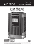
1
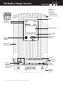
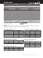
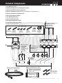
P12
BA TTE R Y C HA R G ER
User Manual
7521
(25A)
CHARGI NG
and 7522
(40A)
12V DC
ALERT
P12
BATTER Y CHARGE R
er
Part Numb nt (Limited)
tput Curre
Total Ou ltage
tput Vo
Ou
al
n
Nomi
nnections
Output Co
t Voltage
AC Inpu
Universal Frequency
t
AC Inpu
Nominal Voltage
ut
Outp
Maximum curacy
ltage Ac
Output Vo g Temperature
Operatin
um
m
ture
i
n
Mi
g Tempera
Operatin
Maximum Temperature
orage
St
um
m
re
i
tu
Min
Tempera
Storage
Maximum c Current
Parasiti
Maximum
CHARGING STAGE
BULK
QuickGuide
Patent Pending
ABSORB PREFLOAT
FLOAT
EQUALIZE – ALL LIGHTS FLASH
www.blues ea.com
7522
7521
40A
25A
12V DC
e
3 positiv
e
1 negativ
AC
90–265V
45–65 Hz
16.0V DC
0.05V DC
°F)
-20°C (-4
8°F)
70°C (15
2°F)
-30°C (-2
6°F)
80°C (17
2mA
7522
7521
40A
25A
e
N° articl
rtie totale CC
so
de
12V
maximum
Courant
nominale
3 positifs
de sortie
Tension
rtie
1 négatif
ents de so
em
ord
CA
Racc
90–265V
iverselle –65 Hz
un
CA
d'entrée minale 45
Tension
CA no
16,0V CC
e d'entrée
Fréquenc
maxi.
0.05V CC
de sortie
Tension on de sortie
(-4°F)
i
ns
e
t
-20
.
de
ni °C
Précision nctionnement mi (158°F)
o
xi. 70°C
ture de f
Tempéra nctionnement ma (-22°F)
o
f
°C
de
-30
ture
Tempéra ockage mini.
6°F)
80°C (17
ture de st
Tempéra ockage maxi.
2mA
ture de st
Tempéra
maxi.
parasite
Courant
UL-1236
ry
iance to
2
Regulato nstruction compl ion) and CSA 22.
d co
tect
e
Design an uding ignition pro l elements of th w
ncl s. Meets al ents. To vie
(i
e
n
ri
ma standard requirem
-0
2
EA
7.
No. 10 and certain NM ifications,
31
cert
ABYC A- rrent regulatory
cu
the most uesea.com/P12.
bl
visit www.
ED
DE SI GN
LED
ASSEMB
TED
and TES
in the
USA
Scan for
additional
product
information
Read and understand the contents of this User Manual. It contains important safety, handling, and operational instructions for the P12 Battery Chargers.
This User Manual describes the product mentioned herein at the time of its publication. Specifications and performance are subject to change at the discretion
of Blue Sea Systems. To view the most current revision of this publication visit bluesea.com/P12.
Table of Contents
Important Safety Instructions
2
P12 Battery Charger Overview
3–4
Specifications5
Installation Tables
• Table A: Minimum Recommended Wire Size
• Table B: Recommended DC Circuit Protection
• Table C: Typical AC Regional Wire Colors
• Table D: AC Wire - Circuit Protection Selection Chart
• Table E: Default Voltages by Battery Type
5
Product Dimensions and Installation Clearances
6
Included Components
7
Supplies Needed
8
Installation Instructions
9–10
Initial Charger Setup
11
Advanced Charger Setup
12–13
Reset to Manufacturer Defaults 13
Absorption Parameters and Timers
14
Temperature Parameters
15
Equalization16–17
Screen Summary
18–19
Alert Screens and Diagnostics
20–21
Optional Installation
22–23
• Automatic Charging Relays (ACRs)
Optional P12 Battery Charger Remote
24–27
Warranty and Contact Information
28
P12 Charge Management System
29
Specifications are subject to change. See bluesea.com/P12 for current information.
1
P12
IMPORTANT SAFETY INSTRUCTIONS
7 5 2 1 A N D 7 5 2 2 B A T T E R Y C HA R GER S
READ AND SAVE THESE INSTRUCTIONS
WARNING
Refers to a potentially hazardous situation which, if not avoided, could result in death or serious injury.
CAUTION
Refers to a potentially hazardous situation which, if not avoided, may result in injury.
WARNING
The P12 Battery Charger should be installed by a qualified marine electrician. Improper installation can result in electrical shock which may
cause serious injury or death. To reduce the risk of electrical shock, mount vertically in a dry, well ventilated location. Charge these battery
types: Flooded, AGM, Gel, or TPPL Lead Acid batteries. Must consult battery manufacturer specifications for other battery types to
avoid damage.
CAUTION
Before beginning electrical installation, read the instruction manual. Disconnect all AC and DC power sources. Do not make final connections
to the batteries until DC connections on the charger are made and verified. Do not make or break electrical connections to batteries while
charging or for up to 30 minutes after charging. Other than parts accessed under the termination cover, there are no user serviceable parts
within the battery charger enclosure. Contact Blue Sea Systems for servicing.
GROUNDING PRECAUTIONS
Marine battery chargers and inverters have two grounding connections, one from the AC system and one from the DC system. ABYC requires
the AC grounding system to be connected to the DC grounding system through the distribution systems. Additionally, the chargers make
connections to both systems. It is very important the systems be connected properly before the charger is installed. Otherwise the charger
grounding system may become the sole connection between AC and DC ground and it may not be sized large enough to provide system wide
safety function. The AC grounding conductor is the conductor with green, or green with yellow stripe included in the AC power cable and should
be sized the same as the power and neutral conductors (see Table C page 5 for AC wire color). This will connect to the right most terminal in
the AC connection block. There is also chassis connection terminal for a DC safety grounding wire. The DC safety ground should be green or
marked green and sized equal to, or one wire size smaller, than the DC charge wires.
Warnings
Specifications
Display
Serial
Number
M4 x 10
Line
Neutral
AC Input
Ground
Max.Torque 20 in-lb (2.25 Nm)
M3 x 25mm
AGC® 10A AC Fuse
DC Safety Ground
− NEG
Battery Bus
+ POS
Battery 1
+ POS
Battery 2
+ POS
Battery 3
DC Output
Max.Torque 75 in-lb (8.47 Nm)
SAFETY
M3 x 30mm
GROUND
Terminations
2
Specifications are subject to change. See bluesea.com/P12 for current information.
Serial No. xxxxxxxxxxx
P12
P12 Batter y Charger Over view
7 5 2 1 A N D 7 5 2 2 B A T T E RY C HA R GER S
The Blue Sea Systems P12 Battery Charger is dry mount device designed for use in marine applications and other harsh environments where reliability, ease of
use, and high performance are of primary importance. To this end, the P12 is designed, assembled, and tested in Bellingham, Washington, USA. Critical
components, including all electronic circuitry, are of US manufacture.
The P12 is designed to charge three electrically independent batteries or battery banks. The P12 has the unique capability to individually move each battery
out of the Absorption charging stage. This ensures batteries near their full charge do not continue to receive high constant voltages necessary in the Absorption
stage. This is optimal treatment for long battery life. Charge Coordination integrates with the Blue Sea Systems family of Automatic Charging Relays (ACR) to
force separation of the battery banks while the P12 is operational, to allow the batteries to individually exit the absorption stage. After fourteen days of
continuous Float, the charger will repeat the normal charge cycle to assure good battery health.
For reliability, the P12 has a rugged cast aluminum housing with high heat dissipating capability for minimum cooling fan run times. The electronic design has
given special consideration to operation in areas of inconsistent AC power quality. The P12 has a Power Factor Corrected nominal AC input range of 90V to
265V AC within which it will produce its full rated DC charging output. It will continue to produce reduced DC output to as low as 75V AC. After a shut down
below 75V AC or when there is interrupted switching between AC sources, like switching between generator and shore power, the P12 will automatically perform
an orderly restart.
Central to the P12’s ease of use is the large plain-language full graphics control screen capable of displaying in French, English, Italian, German and Spanish.
The plain language display enables clear communication with the operator for setting precise charging parameters and providing a broad range of easily understood fault communications and operating history. An optional remote display brings much of this functionality to a secondary location away from the charger.
The P12 contains charge profiles for most batteries available today, including Flooded Lead Acid (FLA), Gel, Thin Plate Pure Lead (TPPL), and Absorbed Glass
Mat (AGM). In addition, a user configurable charge profile is available for other battery types.
The P12 has built-in safety features including: ignition protection, over and under temperature protection (sensed internally and at the batteries), DC reverse
polarity protection, DC over voltage protection, and surge and short circuit protection.
Four Stage Battery Charging
The definitions of the P12 charging stages are defined below. The charging stage LEDs on the front of the charger will indicate the current stage.
Bulk (Constant current)
The Bulk charging stage is the first stage in the battery charging process. It is where a majority of the charging actually takes place leaving batteries at approximately
75% to 80% of their final capacity. The goal of the Bulk stage is to drive current into the batteries quickly to increase their voltage. Once all the batteries have reached the
defined Absorption voltage then the charger will move them into the Absorption stage.
Absorption (Constant voltage)
In the Absorption charging stage the batteries complete their charging by being “topped off”. This is a less aggressive charging stage than bulk where the current going into a
particular battery bank will significantly reduce with time. The conditions for a battery bank to be considered “full” vary based on many different factors. In order for a battery
bank to leave the Absorption stage a number of different parameters must be met. The main parameters are the Absorption Timers which can be seen on
page 14. Outputs move individually from Absorption to Pre-Float. When all batteries have completed Absorption, the charger will move them into the Float stage.
Pre-Float (Constant voltage)
The Pre-Float charging stage is unique to the P12. Since the size of battery banks typically vary from one output to the next, there is a need to charge each bank independently.
Once all batteries are in Absorption battery banks may finish charging at different rates. Once a battery bank has met its unique Absorption parameters the P12 Charger will
independently move it into the Pre-Float stage. Pre-Float is the initial stage to maintain a fully charged battery. Batteries in Pre-Float can have up to a .5V difference
between batteries in Absorption. Up to two outputs can be in Pre-Float simultaneously.
Float (Constant voltage)
Float is the final charging stage for fully charged batteries. Batteries in this stage are being maintained at their defined float voltage. Typically his Float voltage
commonly has a 1.0V or greater difference from the Absorption voltage.
lk
Absor ption
B
u
PreFloat
13.9V
PreFloat
Float
T
Example of Flooded Lead Acid Battery
I
M
E
13.2V
Battery 1
Absor ption
Battery 2
Absor ption
Battery 3
Absor ption
14.4V
Forced Absor ption
Forced Absor ption
lk
14.4V
Absor ption
Battery 2
u
Absor ption
Battery 1
Battery 3
Conventional Three Stage Battery Charging
B
Four Stage Battery Charging
Float
T
I
M
E
13.2V
Example of Flooded Lead Acid Battery
Forced Absorption: A period when batteries are potentially over charged.
Specifications are subject to change. See bluesea.com/P12 for current information.
3
P12
P12 Battery Charger Over view
7 5 2 1 A N D 7 5 2 2 B A T T E R Y C HA R GER S
Mounting holes
Clearance for:
M6, 1/4", or #12
mounting hardware
NOTE: Mounting holes are
not symmetrical please see
dimension drawing on page 6
Fan vent
Charging and
Alert indicators
Graphic LCD Display
Screen selection
buttons
Charging stage
indicators
Scan for
additional
information
Rugged, finned
cast aluminum case
DC output
AGC® 10A AC Fuse
DC Safety Ground
AC strain
relief and
insulating cover.
AC input terminals
under cover.
− NEG
Battery Bus
+ POS
Battery 1
DC Output
+ POS
Battery 2
Max.Torque 75 in-lb (8.47 Nm)
+ POS
Battery 3
Termination
cover latch
DC strain
relief clamp
Termination
insulating
cover
4
Specifications are subject to change. See bluesea.com/P12 for current information.
P12
Specifications
7 5 2 1 A N D 7 5 2 2 B A T T E RY C HA R GER S
7521
7522
Total Output Current
25A
40A
Input AC Current
4.5A @ 100V AC / 2.25A @ 200V AC
7.5A @ 100V AC / 3.75A @ 200V AC
Nominal Output Voltage
12V DC
12V DC
Output Connections
3 positive, 1 negative
3 positive, 1 negative
Universal AC Input Voltage
90V–265V AC
90V–265V AC
Input Frequency Range
45–65 Hz
45–65 Hz
Typical Float Voltage
13.5V DC
13.5V DC
Maximum Available Voltage
16.0V DC
16.0V DC
Output Voltage Accuracy
0.05V DC
0.05V DC
Minimum Operating Temperature
−20°C (−4°F)
−20°C (−4°F)
Maximum Operating Temperature
70°C (158°F)
70°C (158°F)
Minimum Storage Temperature
−30°C (−22°F)
−30°C (−22°F)
Maximum Storage Temperature
80°C (176°F)
80°C (176°F)
Warranty
5 Year
5 Year
Battery Types*
Flooded, Gel, AGM, TPPL (Thin Plate Pure Lead)
160Ah Minimum, Example: 2 x Group 27
330Ah Maximum, Example: 3 x Group 31
Flooded, Gel, AGM, TPPL (Thin Plate Pure Lead)
220Ah Minimum, Example: 2 x Group 31
440Ah Maximum, Example: 4 x Group 31
Recommended for Battery Bank Sizes**
* Consult battery manufacturer specifications for other battery types to avoid damage. Do not mix battery types.
**Battery bank sizes are recommended for optimal charging efficiency-see bluesea.com/P12 for details. Larger and smaller size banks could charge well, but consume slightly
more power over the charging cycle.
Regulatory
Designed and constructed for compliance to UL-1236 Marine, CSA 22.2 No. 107.2, and ABYC A-31 standards. Ignition Protection per ISO 8846, and SAE J1171.
Meets FCC Part 15, Class B requirements. To view current regulatory specifications visit www.bluesea.com/P12.
Table A: Minimum Recommended Wire Size*
Conductor Length in feet (meters)
Table D: AC Wire - Circuit Protection Selection Chart
Charger Rating
7521 (25A)
25A
40A
7522 (40A)
Input Watts
450
750
6 ft (1.83 meters)
14 AWG (2.5mm²)
8 AWG (10mm²)
120V AC Application
4.5A @ 100V AC
7.5A @ 100V AC
10 ft (3.05 meters)
12 AWG (4mm²)
8 AWG (10mm²)
Minimum AC Wire Size
18 AWG (0.75mm²)
16 AWG (1.5mm²)
15 ft (4.57 meters)
10 AWG (6mm²)
6 AWG (16mm²)
Circuit Breaker
10A
15A
20 ft (6.09 meters)
8 AWG (10mm²)
6 AWG (16mm²)
230V AC Application*
2.25A @ 200V AC
3.75A @ 200V AC
25 ft (7.62 meters)
6 AWG (16mm²)
4 AWG (25mm²)
Minimum Wire Size
18 AWG (0.75mm²)
18 AWG (0.75mm²)
Recommended Battery Fuse
30A
60A
Circuit Breaker
5A – 10A
5A – 10A
* Based on 3% voltage drop. If fast charge recovery is important, use larger wire. Double the conductor
length entry to get a 1.5% drop, triple the conductor length to get a 1% voltage drop.
* Typical of Europe
Table B: Recommended DC Circuit Protection
Table E: Default Voltages by Battery Type
Appropriate Fuses and Fuse Holders
Fuse Type
Fuse Holder
Charger Rating
25A
40A
MRBF Terminal Fuses
5191 Terminal Fuse Block
5175 (30A Fuse)
5178 (60A Fuse)
AMI®/MIDI® Fuses
7720 Safety Fuse Block
5250 (30A Fuse)
5253 (60A Fuse)
Table C: Typical AC Regional Wire Colors
Batteries should match in chemistry, although many AGM’s and flooded batteries are
compatible. Based on 25°C (77°F)
Absorb Volts
Float Volts
FLA – Flooded Lead Acid
Type
14.5V
13.5V
AGM – Absorbed Glass Mat
14.35V
13.3V
Gel – Gelled Electrolyte
14.1V
13.5V
TPPL – Thin Plate Pure Lead
14.7V
13.6V¹
12.5V Default
12.5V Default
User Adjustable
Region
Line
Neutral
Ground (Earth)
North America
Black
White
Green
Europe
Brown
Blue
Green-Yellow
Australia/ New Zealand
Brown or Red
Blue or Black
Green-Yellow
¹ Taken from Odyssey Tech Notes, Northstar operation Manual
Specifications are subject to change. See bluesea.com/P12 for current information.
5
P12
Product Dimensions
7 5 2 1 A N D 7 5 2 2 B A T T E R Y C HA R GER S
WARNING
For drip proof performance, and to meet ABYC requirements, the P12 Battery Charger must be mounted vertically as shown below.
7.80" (198mm)
Top mounting
screw centers
Ø0.3" (6.6mm)
Mounting holes
Clearance for:
M6, 1/4", or #12
mounting hardware
NOTE: Mounting
holes are
not symmetrical
11.18"
(284mm)
Mounting
screw
centers
13.00"
(330.6mm)
7.40" (188mm)
3.66"
(93mm)
Bottom mounting
screw centers
8.46"
(215mm)
Installation Clearances
TOP
Recommended
top clearance
1.97" (50mm)
Recommended
clearance
for cooling fan exhaust.
do not block!
5.91" (150mm)
Recommended
side clearance
1.97" (50mm)
Recommended
overall
envelope height
19.00" (480.6mm)
Recommended
overall envelope width
12.40" (315mm)
6
Specifications are subject to change. See bluesea.com/P12 for current information.
Recommended
clearance
for wire access
and inlet airflow.
3.94" (100.2mm)
P12
Included Components
7 5 2 1 A N D 7 5 2 2 B A T T E RY C HA R GER S
1. Four Mounting Screws
2. Two AC Strain Relief and Insulating Cover Screws
3. One AC Strain Relief and Insulating Cover
4. Three AC Termination Screws: AC Line: Gold, AC Neutral: Silver, AC Ground: Green
5. Three DC Strain Relief C-Clamp Screws
6. One DC Strain Relief C-Clamp
7. Four DC Termination Nuts
8. One DC Safety Ground Nut
9. One Battery Temperature Sensor
5
M3 x 30mm pan-head machine screws
10. One Packet of Dielectric Grease
11. Accessory Pack Includes:
Accessory Pack
#12 x 1-1/4"
sheet metal screw
M3 x 25mm
pan-head
machine screw
AC Line
Gold
AC Neutral
Silver
M4 x 10mm
pan-head
machine screws
(Use #1 Phillips screwdriver)
Recommended torque:
5–10 in-lb (0.6–1.1 Nm)
AC Ground
Green
M3 x 30mm
pan-head
machine screw
M6 serrated
flange hex-nut
Screw terminal
plug for ACR
connection
x 25mm pan-head machine screws (Use #1 Phillips screwdriver)
2 M3
Recommended torque: 5–10 in-lb (0.6–1.1 Nm)
3
M4 x 10mm pan-head
machine screws,
(Use #2 Phillips
screwdriver)
Recommended torque:
10–15 in-lb
(1.0–1.8 Nm)
6
7
M6 serrated flange hex-nuts
(Use 10mm socket wrench
with extension)
Recommended torque:
70–80 in-lb (8–9 Nm)
4
serrated
8 M6
flange hex-nut
(see #7 above)
connector with peel and stick
9 RJ11
adhesive, 15 ft (4.6m) long tether
for Temperature Sensor and the
10 Used
Optional Accessory P12 Remote Display
Connections (see pages 24–27). View
the MSDS for the Dielectric Grease at
bluesea.com/P12
1
#12 x 1-1/4" sheet
metal screws (Use #3
Phillips screwdriver)
Dielectric Grease
Specifications are subject to change. See bluesea.com/P12 for current information.
7
Supplies Needed
P12
7 5 2 1 A N D 7 5 2 2 B A T T E R Y C HA R GER S
1. AC Wire (see Table D page 5)
NOTE: Wire length must reach from the panel to the battery charger AC Connections with proper routing, support, drip loops, service loops, and termination.
2. DC Wire: Black or Yellow for negative and red for each positive. (see Table A page 5)
NOTE: Yellow is preferred for negative however diagrams are drawn in black for visibility.
3. Fuse holders for connection to each battery. (see Table B page 5)
4. Fuses for fuse holders. (see Table B page 5)
5.Screwdrivers
• Flat blade screwdriver
• Phillips #1 – for AC Termination cover and DC Termination Strain Relief clamp
• Phillips #2 – for AC termination screws
• Phillips #3 – for mounting screws
6. Socket wrench
• 10mm socket with extension and ratchet handle or nut driver – for DC wire terminations
7. Ring terminals
• #8 ring terminals sized for AC/Supply wire gauge (quantity 3)
•¼” or M6 ring terminals sized for DC wire sizes (quantity 4)
8. Crimping tool or obtain wires that are pre-terminated
9. Appropriate heat shrink if pre-terminated wires were not acquired
8
Specifications are subject to change. See bluesea.com/P12 for current information.
P12
Installation Instructions
7 5 2 1 A N D 7 5 2 2 B A T T E RY C HA R GER S
The P12 Battery Charger default startup mode is “User”. The battery charger will maintain a voltage but will not
charge batteries in this mode. After proper installation see page 11 to set up your battery type.
Installation Steps
1. Before beginning electrical installation, disconnect all positive and negative AC and DC power sources.
DC
AC
2. To reduce the risk of electrical shock, mount the battery charger vertically, in a dry and well ventilated location.
For drip proof installation, mount the battery charger in a vertical orientation.
NOTE: The charger should be located near the batteries to minimize wire length and its associated voltage drop to maximize charging efficiency.
If the batteries are not close together, place the charger near the largest bank of batteries.
3. Remove the AC/DC termination cover by unlatching the yellow tabs. The cover hinges downward as shown.
4. Then remove the AC and DC wire termination strain relief by unfastening the screws.
AC Strain Relief
DC Strain Relief
5. Route DC wires from each charger output to battery fuse holder, see Wiring Connections Diagram page 10.
NOTE: DC wiring should safely reach each battery positive and the battery negative common bus bar. Fuses should be installed at the battery positive
connections to prevent battery power from feeding back into a fault in the wiring, or in the battery charger. See Table A and B on page 5 for recommended values.
Best practices and ABYC standards recommend that every positive wire on the boat outside the engine starting circuit most have circuit protection.
Please reference ABYC E-11 electrical standard for the most up to date recommendations.
Specifications are subject to change. See bluesea.com/P12 for current information.
9
P12
Installation Instructions (continued)
7 5 2 1 A N D 7 5 2 2 B A T T E R Y C HA R GER S
6. Route the AC wires from the charger to the AC panel and terminate wires at the charger.
7. Make the AC source connections to the appropriate panel circuit breaker and leave in the “off” position. (see Table D page 5).
NOTE: Connect AC wiring, but do not energize the circuit until AC covers are installed, DC is connected, and DC fuses are installed.
8. Recommended Connection: Attach the battery temperature sensor wire to the largest battery bank. If all battery banks are the same size attach to bank with the most loads.
Blue Sea Systems recommends using a high quality dielectric grease for remote control and temperature sensor connections.
a.Attach the sensor in the center of the long side of the battery.
b.If multiple batteries are in a battery bank attach sensor in the center between multiple batteries.
c. When external circumstances could create a significant difference in temperature on one side of a battery versus another, always attach temperature sensor on warmest side.
9. Install appropriate DC Fuses. (see Table B page 5)
10. Confirm all connections are accurately installed per
Wiring Connections Diagram.
11. Secure AC and DC strain relief covers and fasten down.
12. Secure the termination cover back over the connected wires
and latch the yellow tabs.
Temperature
Sense
13. Restore AC power and turn on the AC supply circuit
breaker to the battery charger.
RJ11 Port
Remote
Display
14. Perform the chargers setup procedure as outlined in
Initial Charger Setup page 11.
RJ45 Port
Wiring Connections
Fuse
Line
Battery 1
Neutral Ground
AC Connections
#8 (M4) Ring Terminals
DC Safety
Ground
Fuse
Battery 2
Fuse
Battery 3
DC Connections
1/4" (M6) Ring Terminals
Optional Installations see pages 22–23
1. Attach the battery charger remote connection to the back of the P12 Battery Charger Remote using dielectric grease. Connect to the Remote Display/Com
port of the charger.
2. Connect the Automatic Charging Relay(s) (ACR) wire to the ACR Connection port(s)
NOTE: If you have a Blue Sea Systems ACR with Start Isolation it is possible to take advantage of the P12 Battery Chargers ability to integrate with it. The P12
is designed to charge three electrically independent batteries or battery banks. The P12 has the unique capability to individually move each battery out of
Absorption charging stage. This ensures batteries near their full charge do not continue to receive high constant voltages necessary in the Absorption stage. This
is optimal treatment for long battery life. Charge Coordination integrates with the Blue Sea Systems family of Automatic Charging Relays (ACR) to force separation
of the battery bank while the P12 is operational, to allow the batteries to individually exit the absorption stage. (see pages 22–23)
10
Specifications are subject to change. See bluesea.com/P12 for current information.
P12
Initial Charger Setup
7 5 2 1 A N D 7 5 2 2 B A T T E RY C HA R GER S
During Initial Charger Setup, or after resetting to factory defaults, the following screens require user input to provide
functional battery charging.
1. Using the left
or right
arrow button, scroll to the desired language.
Press the Select button.
2. Once the desired language is highlighted, press OK button.
Press the Cancel button to go back.
3. Using the left
or right
arrow button, scroll to the desired battery type.
Press the Select button.
Note: If User mode is selected batteries will not charge until Absorb and Float voltages are altered.
See page 12-13 for Advanced Charger Setup.
4. Once the desired battery type is highlighted, press the OK button.
Press the Cancel button to go back.
5. Press the Back button twice to go to the Charger Summary screen. Note: If battery type is unknown, see the label on the battery or contact a qualified marine electrician.
CAUTION
Selecting a battery type different from the connected batteries could limit the life of the
batteries and damage them.
Your charger is now operational.
For advanced setup options and information on Absorb and Float voltage, as well as absorb timers,
See page 12.
Specifications are subject to change. See bluesea.com/P12 for current information.
11
P12
Advanced Charger Setup
7 5 2 1 A N D 7 5 2 2 B A T T E R Y C HA R GER S
Complete this setup to change language, limit fan noise, adjust backlight display and limit AC current draw.
1. Press the Menu button.
2. Press the left
or right
arrow buttons to scroll to the Fan Speed window
3. Press the Select button.
4. Press the up
or down
arrow buttons to select the desired speed.
a.
High: The fan will spin up to its maximum speed. This is the recommended setting for optimal performance.
b.
Low: The fan will spin up to a designated speed (below max). If there is a significant load on the charger, it may limit its maximum output current in
order to maintain a safe internal temperature.
c.
Off: Forces the Fan to stay off. If there is significant load on the charger, it may limit its maximum output current to maintain a safe internal temperature.
NOTE: Selecting High or Low will not necessarily turn the fan immediately on or increase the fan speed. In either of these settings the charger will only alter the fan
speed if the internal temperature rises enough to warrant fan circulation. The fan Low setting is for quiet mode.
5. Press the OK button once desired speed is reached.
6. Press the left
or right
arrow buttons to scroll to the Max Output window.
7. Press the Select button.
8. Press the up or down arrow buttons to select the desired maximum output amperage. Low output may be selected to reduce load on the AC source.
AC current is approximately one tenth of the DC current at 120V line voltage and one twentieth of the DC current at 240V line voltage.
NOTE: The designated maximum amperage is the total available amperage to be supplied among all 3 outputs. Selecting an amperage less than the maximum
could result in under charging of batteries.
9. Press the OK button once desired max amperage output is reached.
10. Press the left
or right
arrow buttons to scroll to the Display window.
11.Press the Select button.
12. Press the up
or down
arrow buttons to scroll to the desired display setting.
13. Press the Select button on the desired display setting to enable editing that setting.
a. Once selected, the amount of contrast and backlight can be adjusted using the left
b. Press the OK button to enable desired setting.
and right
arrow buttons.
14. Scroll to Backlight Timer and press the Select button.
a. Using the left
and right
b. The backlight timer can be adjusted between 5 and 59 seconds. It may also be set permanently on or permanently off.
arrow buttons you may adjust the length of seconds the backlight will remain on.
15. Press the OK button once desired backlight setting is reached.
16. Scroll to Language and press the Select button to adjust the display language.
17. Using the left
or right
arrow buttons scroll to the desired language.
18. Press the OK button.
12
Specifications are subject to change. See bluesea.com/P12 for current information.
Advanced Charger Setup
P12
(continued)
7 5 2 1 A N D 7 5 2 2 B A T T E RY C HA R GER S
19. Once desired display settings are enabled press Back.
20. Press the left
or right
arrow button to scroll to the Battery window.
21. Press the Select button.
Table E: Default Voltages by Battery Type
Batteries should match in chemistry, although many AGM’s and flooded batteries are
compatible. Based on 25°C (77°F)
Absorb Volts
Float Volts
FLA – Flooded Lead Acid
Type
14.5V
13.5V
AGM – Absorbed Glass Mat
14.35V
13.3V
Gel – Gelled Electrolyte
14.1V
13.5V
TPPL – Thin Plate Pure Lead
14.7V
13.6V¹
12.5V Default
12.5V Default
User Adjustable
¹ Taken from Odyssey Tech Notes, Northstar operation Manual
22. While the cursor blinks on battery type press the Select button.
23. Use the left
or right
arrow buttons to scroll to desired battery type.
24. Press the OK button.
25. For optimal charging it is recommended to set absorption timers and End Absorb Amps. If Amp Hour Capacity is known, continue to page 14 for more information.
NOTE: to adjust Absorb and Float voltage “User” must be the selected battery type. The default Absorb voltages for each battery type can be seen in Table E above.
Warning: Incorrect Absorb and Float voltages could reduce the life of your batteries. Contact your battery manufacturer for recommended Absorb and Float voltages.
CAUTION
Selecting a battery type different from the connected batteries could limit the life of the batteries and damage them.
26. Press the Back button twice to return to the Charger Summary screen.
27. Your P12 Battery Charger is now setup and fully operational.
Reset to Manufacturer Defaults
To reset the P12 Battery Charger to factory defaults, press and hold the two right buttons for ten seconds.
Press the OK button for five seconds to proceed with resetting to factory defaults or press the Cancel button to return to the previous screen.
Note: Resetting the P12 Battery Charger to factory defaults will erase previously saved data and settings.
Specifications are subject to change. See bluesea.com/P12 for current information.
13
P12
Absorption Parameters and Timers
7 5 2 1 A N D 7 5 2 2 B A T T E R Y C HA R GER S
CAUTION
The default Absorption Timer values are set to satisfy a majority of the battery configurations that exist. Unwarranted changes to Absorption timers could
result in damage to the batteries and reduced battery life. To optimize Absorption Timer based on specific configurations please contact your
battery manufacturer for setting guidelines for your specific battery.
The Absorption stage is the charging stage in which a battery “fills” to max capacity. Absorption timers help define the amount of time a battery bank will
remain in the Absorption stage. Having a correct Absorption time is vital for optimum charging of a battery bank. Under Absorption can lead to a battery
being consistently under-charged causing sulfate buildup. Over Absorption can dry out the electrolytes in a battery. Both of these conditions can lead to
reduced battery life.
There are three user selectable parameters that help define when a connected battery bank will be moved from Absorption to either Pre-Float, or Float.
End Absorption Amps
The maximum amount of current that a battery bank can receive while in Absorption and still change to Float. If a
load is active and drawing more than the designated End Absorption Amps, the battery bank will not leave Absorption
until the maximum Absorption time is met. For a battery bank to move from Absorption to Float before the maximum
Absorption time is met, the minimum Absorption time must be met, and the amperage output must be less than or
equal to the designated End Absorb Amps.
Recommended End Absorption Amps
End Absorb Amps will vary based on your specific system. To set the correct End Absorb Amps it is recommended
that you monitor the amperage entering your battery banks near the end of the absorption cycle. Constant loads
Table F: Approximate End Absorb Amps
(1% of Ah Capacity)
Flooded
will affect this number, and should be incorporated into End Absorb Amps if present. However, in a typical system
Group
Size
24
Ah
(without constant loads) it is recommended that the End Absorb Amps be 1% of your battery banks amp-hour
capacity (see Table F).
AGM
Gel
TPPL
75
1% End Ah
Amps
0.8
79
1% End Ah
Amps
0.8
73
1% End Ah
Amps
0.7
76
1% End
Amps
0.8
27
90
0.9
0.9
86
0.9
91
0.9
31
105 1.1
105 1.1
97
1.0
102 1.0
4D
150 1.5
198 2.0
183 1.8
185 1.9
8D
200 2.0
245 2.5
225 2.3
228 2.3
92
Minimum Absorption Time: 1 hour default
The minimum amount of time a battery bank will be in Absorption. The battery charger will not move a battery from Absorb to Float unless the Minimum Absorption Time is met.
Maximum Absorption Time: 4 hour default
The maximum amount of time a battery bank can remain in Absorption. While still maintaining its Absorption voltage, if a battery has been in Absorption for the maximum
designated time it will move into Float even if End Absorb Amps is elevated. This is commonly caused when active loads are present.
Recommended Absorption Time
Minimum and Maximum Absorb Times can vary from installation to installation. It is recommended that Minimum and Maximum Absorption Times be based on the time it takes
a battery bank to reach End Absorb Amps. Read and understand the End Absorb Amps section above and set according to your system. After an accurate End Absorb Amperage
is set, monitor the minimum and maximum time it takes for each battery bank to reach their End Absorb Amps. The Minimum Absorb Time should be based on the minimum time
it takes a particular battery bank to reach End Absorb Amps. The Maximum Absorb Time should be an hour more than it takes a deeply discharged battery bank to reach End
Absorb Amps. It is recommended to monitor charging while the battery banks are in different states of discharge to get the most accurate Minimum and Maximum Absorb Times.
Absorption Timer Counter
The P12 battery charger uses a counter to determine the amount of time a battery bank should remain in Absorb relative to the Maximum Absorb Time. The Absorb timers counter
can be seen in the System Status Screen and also referenced on page 19.
Available Timer Modes
When in Float or Standby, the timer will pause.
When in Pre-Float mode the timer for that channel will pause.
When in Bulk mode the remaining time will increase.
When in Absorption mode, the remaining time will decrease.
Once a battery bank’s Absorb timer is reduced to zero, then its output will be changed to Pre-Float. There are
other factors in a battery bank leaving the Absorption stage prior to the Absorb timer running out. Once all battery
banks leave Absorption, all outputs will enter the Float stage.
14
Specifications are subject to change. See bluesea.com/P12 for current information.
P12
Temperature Parameters
7 5 2 1 A N D 7 5 2 2 B A T T E RY C HA R GER S
WARNING
Altering the default temperature parameters could cause serious property or personal damage. Contact your battery manufacturer to clarify the correct
temperature parameters for your specific batteries.
NOTE: Temperature parameters refer to the temperature measured at the temperature sensor, not the temperature of the charger. In this manual all temperatures
will be referenced in degrees in Celsius (°C). The user selectable range for battery temperature parameters is -20°C to 60°C. Ensure proper placement of battery
temperature sensor by referencing Step 8 on page 10
Minimum Charge Temperature: The default is 0ºC
The lowest temperature of the sensor in which the charger will continue charging. If the temperature sensor falls below the minimum charge temperature, the charger will enter
standby mode, and cease to charge.
CAUTION
Charging batteries below 0°C can be potentially dangerous. Internal battery liquid can freeze and charging a frozen battery could cause serious property or
personal damage. Contact your battery manufacturer for minimum safe charging temperature for your batteries before altering.
Maximum Charge Temperature: The default is 50ºC
The highest temperature of the sensor in which the charger will continue charging. If the temperature sensor increases above the maximum charge temperature, the charger will
enter standby mode, and cease to charge.
CAUTION
Charging batteries above 50°C can be potentially dangerous. Contact your battery manufacturer for the maximum safe charging temperature for your
batteries before altering.
Battery Temperature Compensation (Tempco)
Battery temperature compensation is output voltage regulation based on battery temperature variances. Since batteries can see extreme temperature differences it is important
to regulate output voltage with temperature. A battery in a freezing environment should not be charged the same as a battery in a hot environment. The P12 Battery Charger
is set at a baseline of 25°C. Every degree variance from this baseline will result in a voltage variance on all outputs. For every degree above 25°C the charger will reduce all
output voltages by the value defined in Battery Tempco. For every degree below 25°C the charger will increase all output voltages by the value defined in Battery Tempco. For
example, with the default Battery Tempco set to -30mv/°C if the temperature sensor reads 26°C, then all output voltages will be reduced by .03V (30mv). If given the same
Battery Tempco and the temperature sensor reads 24°C, then all output voltages will be increased by .03V (30mv).
CAUTION
Altering the battery temperature compensation value incorrectly can cause adverse effects on your battery, by potentially reducing its life. Contact your
battery manufacturer to find out the specific temperature compensation parameters for your batteries.
Specifications are subject to change. See bluesea.com/P12 for current information.
15
Equalization
P12
7 5 2 1 A N D 7 5 2 2 B A T T E R Y C HA R GER S
WARNING
Equalization is a user selectable and potentially dangerous charging stage that should not be performed without sufficient knowledge. Personal or property
damage may occur if equalization is performed incorrectly. It is highly recommended that you seek professional guidance before performing equalization.
Equalization causes off gassing of harmful chemicals inside of the battery. Only perform equalization while the batteries are in a well-ventilated area away
from persons and animals.
CAUTION
Equalization may only be performed on flooded (wet) lead acid batteries. Serious personal or property damage may occur if equalization is
performed on any battery type other than flooded lead acid batteries.
Definition of Equalization
Equalization is an increased voltage overcharge performed only on flooded lead acid batteries. Once a battery is fully charged equalization increases the voltage and forces
additional charge into the battery to combat negative chemical side effects that can occur in flooded batteries. It is done to compensate for stratification, a
condition where the acid concentration is uneven throughout the battery, and typically higher at the bottom. It is also done to remove sulfate crystals that build up
on the lead plates in flooded batteries.
Prior to Equalization
Contact the manufacturer of your flooded lead acid batteries to confirm the parameters of equalizing your specific batteries. Every battery manufacturer defines different
equalization parameters which are important to understand prior to equalization. All batteries must be fully charged and not under load from any device. The P12 Battery
Charger will not allow equalization to occur if batteries are discharged or powering any device.
Equalization Process
1. Confirm batteries are fully charged by verifying the charger is in Float mode with no active loads.
2. Turn off or disconnect all DC devices that are connected to the batteries. Disconnect the battery banks not being Equalized by removing the fuses at
the battery connection.
NOTE: Equalization will not occur if steps 1 and 2 are not met.
3. Confirm use of flooded lead acid batteries.
NOTE: Equalization will only occur if the battery type is set to “Flooded Lead Acid” (FLA) or “User”. Do not proceed if you are using any other battery type.
See bluesea.com/P12 for details.
4. From any screen simultaneously press and hold the left and right most buttons for 5 seconds.
5. Read and understand the caution screen before proceeding.
6.Press “I Accept” to continue.
7. Using the battery manufacturer’s parameters, input the correct equalization voltage, amperage, and time on the battery bank you would like to equalize.
You may only equalize one battery bank at a time.
NOTE: Equalization parameters vary based on battery size. Confirm parameters for every battery connected to the charger before continuing.
16
Specifications are subject to change. See bluesea.com/P12 for current information.
Equalization
8. To change battery, use the up
P12
(continued)
down
7 5 2 1 A N D 7 5 2 2 B A T T E RY C HA R GER S
arrow buttons to scroll the cursor to the Bat1 window.
9. Press the Select button.
10. Using the left
and right
arrow buttons, scroll between the three different battery banks connected to the charger.
11. Confirm Equalization parameters for the battery you wish to equalize.
12. Using the up
down
arrow buttons, scroll the cursor to the StartEQ window.
13. Press the Select button.
14. The charger will now begin to equalize and will display.
15. Monitor batteries and battery temperature throughout the Equalization process.
16. You may pause Equalization at any time by pressing the pause
button.
17. If at any point during Equalization a DC load is applied to the battery being equalized, Equalization will stop.
NOTE: If you receive the below warning screen confirm batteries are fully charged and all DC loads connected to the batteries are turned off. Once complete proceed
back to step 1 of the Equalization process.
18. You may stop Equalization at any time by pressing the stop
button.
NOTE: Pressing stop will return you to the Charger Summary screen.
19. Once the max Equalization voltage is reached the battery bank will begin to equalize for the designated Equalization time.
20. After the designated Equalization time is met Equalization will stop and the charger will return to the Charger Summary Screen.
Specifications are subject to change. See bluesea.com/P12 for current information.
17
Screen Summary
Charger Summary
The Charger Summary screen provides data of the battery’s status while the battery charger is operational.
Options:
-
Press the History button to view previous charger performance
-
Press the Menu button to view the Configuration Menu
How to Get Here:
From other screens in the charger, select the Back button.
Configuration Menu
The Configuration Menu has six user selections that allow modifications to Fan Speed, Charger Output,
Display, Battery Parameters, Temperature Limits, and Diagnostics.
Options:
-
Scroll through the menu and select the desired option.
How to Get Here:
From the Charger Summary Screen, select the Menu button. From other screens, select the Back button.
Display Setup
The Display Setup allows the user to customize the display settings.
Options:
-
Adjust Contrast
-
Adjust Backlighting
-
Set a Backlight Timer (length of time backlight will remain on)
-
Select a language
How to Get Here:
From the Configuration Menu, select the Display button.
Charger Setup
The Charger Setup Menu is where the Battery Type and Absorb Timers are selected. Caution read
Absorption Parameters and Timers on page 14 before adjusting absorb timers.
Options:
-
Select Battery Type or set Absorb Timers.
-
If “User” is the selected battery type you may also adjust Absorb and Float voltage.
See page 14 for more information
How to Get Here:
From the Configuration Menu, select the Battery button.
18
Specifications are subject to change. See bluesea.com/P12 for current information.
P12
7 5 2 1 A N D 7 5 2 2 B A T T E R Y C HA R GER S
Screen Summary
P12
(continued)
7 5 2 1 A N D 7 5 2 2 B A T T E RY C HA R GER S
Temperature Parameters
The Temperature Parameters screen indicates the minimum and maximum operating temperature based on the
temperature sensor. Read the Temperature Parameters section on page 15 before making any adjustments.
Options:
-
Select Units and temperature parameters to adjust.
How to Get Here:
From the Configuration Menu, select Temp Limits.
System Status
The System Status screen indicates which systems are functioning and the current firmware installed on the device.
Options:
-
Select the Back button to go to the Configuration Menu.
-
Select the Next button to view the status of the Absorb timers.
How to Get Here:
From the Configuration Menu, select Diagnostics
System Status Absorb Timers
The System Status Absorb Timers screen indicates the current Absorb time of each battery bank, as well as the
AC input voltage. The up
down
arrows indicate if time is being added or subtracted from the timer. If
paused
the charger is in Float or Standby and the Absorb Timer will remain at its current time.
Read about Absorb Timers on page 14.
Options:
-
Select the Back button to go to the System Status Screen.
-
Select the Next button to view the charger Hour Meter Screen.
How to Get Here:
From the System Status Screen, select the Next button.
System Status Hour Meter
The System Status Hour Meter screen displays the overall time the charger has spent running at different
amperage levels.
Options:
-
Select the Back button to go to the System Status Absorb Timers Screen.
How to Get Here:
From the System Status Absorb Timers Screen, select the Next button.
History
The History screen graphically displays the charging voltage and amperages per battery.
Options:
-
Select the Back button to go to the Charger Summary Screen.
-
Select individual batteries to view charging summary.
-
Press and hold any Bat button for 3 seconds to switch from First 8 Hour view to Continuous.
How to Get Here:
From the Charger Summary Screen, select the History button.
Specifications are subject to change. See bluesea.com/P12 for current information.
19
Alert Screens and Diagnostics
P12
7 5 2 1 A N D 7 5 2 2 B A T T E R Y C HA R GER S
If at any time during the chargers life the red Alert light goes on, then the charger is not providing optimal performance.
The below Alerts encompass all of the possibilities for the charger to under perform. Alerts will be indicated by the red
Alert light as well as a pop-up screen explaining the reason.
Reverse Polarity or Short Circuit
The P12 Battery Charger has the ability to determine if batteries are incorrectly connected to the charger. Upon
supplying AC power to the charger if a reverse polarity or short circuit situation exists the Reverse Polarity or Short
Circuit Screen will be displayed. Shut off AC power and correct the connection issue. Once corrected, turn on AC
power and attempt to use the battery charger as normal. If no alert screen displays then the charger is
fully operational.
Reverse Polarity or Short
Turn Off AC Power
Check DC Connections
WARNING
If AC power is being supplied to the battery charger and batteries are connected incorrectly (reverse polarity or
short circuit), damage will occur to the internals of the battery charger. This will render the battery charger
non-operational. Never make connections while AC power is supplied to the battery charger. Personal and property damage may occur and the chargers warranty will be void.
Thermal Regulation
The P12 Battery Charger is equipped with an intelligent thermal regulation device for safe charging. If at any point
during charging a thermometer image begins to blink in the upper right hand corner of the screen, then the charger
has entered Thermal Regulation. This is not a failure, but a reduced current output state. While in this state the
internal temperature is being regulated by controlling the maximum output current. The maximum output current will
appear at the bottom of the Charger Summary Screen indicating the total amount of current available to supply all
outputs. While in Thermal Regulation, the charger will reduce output current to keep the charger at a safe operating
temperature. The output can be regulated all the way down to zero but is not likely. The most common correction for
this state is to increase the fan speed to High. If the fan speed is already set to High check for blockage around the
fan vent that can be removed. If the condition persists, it is advisable to reposition the battery charger in a cooler,
more ventilated location.
Fan
The P12 Battery Charger is equipped with a variable speed fan. The fan is used to dissipate warm air produced from
high output currents during charging. The aluminum case of the P12 Battery Charger provides a large amount of heat
dissipation but for optimal performance the fan must be performing properly. If at any point the fan fails to perform
at its designated setting the Fan Alert Screen will appear. If this alert screen appears shut off AC power to the
battery charger as well as all battery connections. Determine if there is a blockage in or around the fan vent and
correct. Turn on AC power and check to see if the Fan Alert Screen appears. If the Fan Alert Screen does not appear
and the fan seems to be operating correctly, then continue to use the battery charger normally. If the Fan Alert
Screen appears contact Blue Sea Systems for fan replacement instructions.
Fan Fault
Check Fan for Blockage
Battery Temperature Sensor
As discussed in the Temperature Parameters section (page 15), there is an external battery temperature sensor
supplied with the unit. If at any point the temperature sensor records a temperature beyond the defined temperature
limits, the battery charger will display the Battery Temperature Alert Screen. In this situation all battery charging will
stop until the proper battery temperature is restored. Normal operation will not commence unless two degrees within
the temperature parameters. For example, if the maximum temperature parameter is set to 50°C and the
temperature sensor reads 51°C then the Battery Temperature Alert Screen will display. In this situation the battery
charger will not charge until the battery temperature sensor reads a maximum of 48°C. If no temperature sensor is
in use then battery temperature is not monitored and this alert will not be displayed.
Battery Temperature
Out of Limits
CAUTION
Alteration of battery temperature parameters without sufficient knowledge is dangerous and can cause personal or property harm. If the battery temperature sensor goes
outside a designated parameter, contact your battery manufacturer for further information on specific battery temperatures.
Internal Temperature Sensor
The P12 Battery Charger is equipped with two internal temperature sensors. These sensors are unrelated to the
supplied external battery temperature sensor. If the Internal Temperature Sensor Alert Screen appears, then one
or more of the internal temperature sensors is not recording correct temperature data. Once in this state all battery
charging will stop. This form of temperature alert can not be corrected by the user. Contact Blue Sea Systems for
further information regarding internal temperature sensor alerts.
20
Specifications are subject to change. See bluesea.com/P12 for current information.
Internal Temp Below -20° C
Charger Will Restart When
Internal Temp Above -18° C
Alert Screens and Diagnostics
(continued)
P12
7 5 2 1 A N D 7 5 2 2 B A T T E RY C HA R GER S
AC Input Voltage Too Low
The minimum input voltage for the P12 Battery Charger is 90V AC. However, due to common voltage sags caused
by spikes in power, the internal hardware of the P12 Battery Charger can continue to charge for brief periods
below 90V AC. If the AC input voltage drops below 75V AC, the alert screen on the right will appear. While in this
state the charger will cease to charge any batteries. Shut off power at the AC source for two minutes, and then
restart. If the alert screen persists, attempt to use a different AC power source, or contact an electrician to
diagnose the problem.
AC Input Voltage too Low
Check for Proper AC Source
AC Input Voltage Too High
The maximum input voltage for the P12 Battery Charger is 265V AC. If the input voltage is above 265V AC the
alert screen on the right will appear. In this state the charger will cease to charge any batteries. Shut off power at
the AC source for two minutes and then restart. If the alert screen persists, attempt to use a different AC power
source, or contact an electrician to diagnose the problem.
AC Input Voltage Too High
Check for Proper AC Source
DC Output Voltage Too High
If at any point the charger detects a DC output voltage greater than 17.8V DC for five seconds, then the alert
screen on the right will appear. In this state the charger will cease to charge any batteries in order to prevent
damage. Shut off AC power for two minutes, and then restart. If the alert screen persists, shut off AC power and
contact Blue Sea Systems for further assistance.
DC Output Voltage Too High
Charger is off to prevent damage
Disconnect AC for 2 mins. then restart
DC Fuse
The P12 Battery Charger has two internal DC fuses that are not accessible by the user. If the DC Fuse Alert Screen
appears, disconnect AC power and all battery connections. The battery charger will require servicing by Blue Sea
Systems. No attempts should be made to replace the fuses by the user. Contact Blue Sea Systems for further
instructions regarding DC fuse replacement.
Internal Fuse Failure.
Contact Blue Sea Systems
360.738.8230
CAUTION
Any attempt to replace the DC fuses will void warranty.
Hardware Failure
There are many complex internal electrical components on the P12 Battery Charger. If any of the vital hardware
components fail the Hardware Failure Alert Screen will appear. Shut off AC power for two minutes, and then
attempt to restart. If there is no longer a Hardware Failure Alert Screen, proceed to use the charger normally. If the
Hardware Failure Alert Screen persists, disconnect AC power and all battery connections, and contact Blue Sea
Systems for further assistance.
Hardware Fault
Turn Off AC For 2 Minutes
Then Turn Power On
Equalization Overload
If at any point during equalization the total output current of the battery charger is greater than the defined
Maximum Equalization Current the Equalization Overload Alert Screen will appear. To correct, confirm batteries
are fully charged, and all loads are turned off prior to equalization. If mandatory 24-hour loads are present you may
adjust the Maximum Equalization Current accordingly. Once corrected, the equalization process must be restarted.
EQ stopped-Max Current Limit
Make sure battery is charged
and all loads removed!
WARNING
Increasing the Maximum Equalization Current beyond your battery manufacturers recommendations is potentially
dangerous. Consult your battery manufacturer for proper equalization currents.
Specifications are subject to change. See bluesea.com/P12 for current information.
21
P12
Optional Installation
7 5 2 1 A N D 7 5 2 2 B A T T E R Y C HA R GER S
Integrate the P12 Battery Charger with Blue Sea Systems Automatic Charging Relays to take
advantage of Charge Coordination.
NOTE: If you have a Blue Sea Systems ACR with Start Isolation, it is possible to take advantage of your P12 charger’s ability to integrate in order to optimize
charging of your batteries.
Automatic Charging Relays (ACRs) combine battery banks when a charging voltage is present in order to share charge between battery banks. However, due to the P12 Battery
Charger’s ability to independently optimize charging for each battery bank it is favorable to isolate all battery banks by disengaging the ACR(s) ability to combine.
NOTE: The P12 Battery Charger can integrate with up to two Automatic Charging Relays (ACRs)
SI-ACR and m-ACR Installation Instructions (PN 7610 and PN 7601) to Enable Start Isolation
1. Disconnect the DC Negative (Ground) wire going to the ACR.
2. If present, disconnect the Start Isolation wire connected to ACR.
3. Connect a wire from the ACR 1 port marked “SI” (Start Isolation) on the P12 Battery Charger to the Start Isolation terminal (SI) on the ACR.
4. Connect a wire from the ACR 1 terminal marked “ES” (Engine Start Switch) on the P12 Battery Charger to the terminal or wire running from the start key switch to the starter solenoid. Make this connection through an in-line fuse of 1 to 10 Amps.
NOTE: This connection can be made at the start key switch or at the starter solenoid, but must be to the line that is +12V DC positive only when cranking. Connection
to a line that is positive while the engine is normally running will prevent the charging relay from working properly.
5. Re-connect DC Negative (Ground) wire on the ACR
6. If connecting two ACRs, repeat steps 1 through 5 using the second ACR, engine, and the P12 Battery Charger ports associated with ACR 2
SI ES ES SI
ACR 1 ACR 2
SI: Start Isolation (ACR) Temperature
ES: Engine Start Switch Sensor
OPTIONAL CONNECTION
Remote
Display
OPTIONAL CONNECTION
FUSE
ENGINE
START
SWITCH
SI ES ES SI
ACR 1 ACR 2
ON
START
OFF
SI: Start Isolation (ACR) Temperature
ES: Engine Start Switch Sensor
Remote
Display
7520
BATTERY CHARGER LED REMOTE
Automatic
Charging
Relay
Automatic
Charging
Relay
START
HOUSE
FUSE
REMOTE LED
START
ISOLATION
GROUND
REMOTE LED
START
ISOLATION
FUSE
GROUND
FUSE
FUSE
ENGINE
START
SWITCH
FUSE
ON
START
OFF
DC GROUND
START
22
Specifications are subject to change. See bluesea.com/P12 for current information.
Optional Installation
P12
(continued)
7 5 2 1 A N D 7 5 2 2 B A T T E RY C HA R GER S
ML-ACR Installation Instructions (PN 7620 and PN 7622) to Enable Start Isolation*
1. Disconnect the black ground wire connected to the ML-ACR wire harness.
2. If present, disconnect all Start Isolation wires connected to the Brown, Green, and Orange wires in ML-ACR wire harness.
3. Connect a wire from the ACR 1 port marked “SI” (Start Isolation) on the P12 Battery Charger to both the Brown and Green wires in the ML-ACR wire harness.
NOTE: Connecting the “SI” (Start Isolation) wire to only one of the ML-ACR isolation wires will not properly integrate the P12 battery charger with your ML-ACR.
4. Connect a wire from the ACR 1 terminal marked “ES” (Engine Start Switch) to the terminal or wire running from the start key switch to the starter solenoid.
NOTE: This connection can be made at the start key switch or at the starter solenoid, but must be to the line that is +12V DC positive only when cranking. Connection to
a line that is positive while the engine is normally running will prevent the charging relay from working properly.
5. Re-connect the black DC Negative (Ground) wire in the ML-ACR wire harness
6. If connecting two ML-ACRs repeat steps 1 through 5 using the second ML-ACR, engine, and the P12 Battery Charger ports associated with ACR 2
*The ML-ACRs also support “Engine Isolation” which keeps an ACR open if two engines are running
simultaneously. Operating in this mode while using
Charger Coordination requires a special installation.
See bluesea.com/P12 for details.
SI ES ES SI
ACR 1 ACR 2
SI: Start Isolation (ACR) Temperature
ES: Engine Start Switch Sensor
OPTIONAL CONNECTION
ENGINE
START
SWITCH
OPTIONAL CONNECTION
SI ES ES SI
ACR 1 ACR 2
ON
START
OFF
SI: Start Isolation (ACR) Temperature
ES: Engine Start Switch Sensor
START
ML-Series
Automatic
Charging
Relay
Remote
Display
Remote
Display
ML-Series
Automatic
Charging
Relay
ENGINE
START
SWITCH
ON
START
OFF
START
7520
BATTERY CHARGER LED REMOTE
A
B
HOUSE
START ISOLATION #1 (BROWN)
START ISOLATION #2 (GREEN)
A
B
ISOLATION #1 (BROWN)
ISOLATION #2 (GREEN)
ISOLATION #3 (ORANGE)
ENGINE ISOLATION #3 (ORANGE)
GROUND (BLACK)
GROUND (BLACK)
DC GROUND
Specifications are subject to change. See bluesea.com/P12 for current information.
23
P12
Optional Accessor y
7 5 2 0 B A T T E R Y C HA R GER R EMOTE
P12 Battery Charger Remote
Indicates battery charger stage, alerts, and controls basic battery charger functions
LED Indicators
Scan for
additional
product
information
•Charging: Quick check for green light confirms charging
• Charge Stage: Displays charging stage including PreFloat for each battery
•Equalize: Indicates when the charger is in equalization mode
• Fan Mode: Indicates charger’s internal fan mode
• Charge Output: Displays the percentage of output current for each battery. Will also indicate maximum output setting when maximum output is adjusted
to accommodate for AC source limitations.
•Alert: Provides warning and alert status for quick diagnostics
Four Control Buttons
•Fan: User adjustable settings (OFF, LOW, or HIGH)
• Dim/ Alarm: Provides adjustment to brightness of LEDs on display as well as Silence function for alarms.
•Output: User adjustable charger output when AC source limitations exist that require lowering the AC current draw.
•Standby: Places P12 Battery Charger into standby mode
Specifications
Minimum Operating Temperature
Maximum Operating Temperature
Minimum Storage Temperature
Maximum Storage Temperature
Mounting Hole Cutout
Dimensions
Height: Width: Depth: Mounting Hardware Included
−20°C (−4°F)
60°C (140°F)
−30°C (−22°F)
70°C (158°F)
1-1/4” (31.75 mm)
3.01” (76.56 mm)
4.15” (105.46 mm)
.95” (24.01 mm)
#6 Screws
Electrical:
On State Operating Current
<300mA sourced from charger
Communications:
Protocol
Maximum Cable Length Cable Regulatory
Proprietary
150 ft (45.7 m)
Cat5e (Standard US)
Surface Mount Gasket creates an IP67 waterproof seal on unit face--temporary immersion for 30 minutes.
Cable Connection
The P12 Battery Charger Remote uses one Cat5e cable for communication and power.
P12 Battery
Charger Remote
P12 Battery Charger
RJ45 Port
24
Specifications are subject to change. See bluesea.com/P12 for current information.
P12
Included Components
7 5 2 0 B A T T E R Y C HAR GER R EMOTE
1. Four Mounting Screws
2. One Cover
1" pan-head sheet metal screws
1 #6(#2xPhillips
screwdriver)
3. One Remote Assembly
4. One Mounting Gasket
Recommended torque:
5–10 in-lb (0.6–1.1 Nm)
5. One 25 ft (7.6 m) Cat5e Cable
6. One Packet of Dielectric Grease
Dielectric Grease
4
3
for Temperature Sensor and
6 Used
Remote Display Connections. View
the MSDS for the Dielectric Grease
at bluesea.com/P12
2
5
Dimensioned Drawing
0.57"
(14.36mm)
Mounting Hole Cutout
Ø1-1/4"
(31.75mm)
4.15"
(105.46mm)
Clearance holes
for #6 screws
2.52"
(63.88mm)
3.01"
1.50"
(76.56mm) (38.10mm)
2.90"
(73.70mm)
3.69"
(93.66mm)
0.38"
(9.65mm)
Specifications are subject to change. See bluesea.com/P12 for current information.
25
P12
Display Indicators
7 5 2 0 B A T T E R Y C HA R GE R R EMOTE
4.Charge Output
1.Charging
2.Charge Stage
7520 BATTERY CHARGER REMOTE
Charge Stage
Charge Output
BULK
FLOAT
EQUALIZE
PREFLOAT
ABSORB
2
1
3
EQUALIZE
Fan Mode
LOW
HIGH
QuickGuide
5.Thermal Regulation and
6.Internal Temperature Sensor
7.Battery Temperature Sensor
75%
FLOAT
OFF
Alert
100%
BULK
ABSORB
PREFLOAT
3.Fan Mode
P12
CHARGING
8.Fan
50%
25%
DC
9.DC Fuse
10%
AC
10.AC Input Voltage
Too High or Low
<5%
DIM /
13. Fan Mode
1
2
3
11.Reverse Polarity
or Short Circuit
OUTPUT
12.Hardware Failure,
DC Output Voltage Too High, or Equalization Overload
15. Output
14. DIM/Alarm
16. Standby
1.Charging:
SOLID ON (Green): Indicates Charging mode and will operate according to its charging stage.
BLINKING (Green): Transitioning from Standby to a Charging state.
OFF: Standby mode - will not charge a battery or supply current to loads.
2.Charge Stage:
Bulk - BLINKING (Green): Indicates Bulk stage on all batteries
Absorb - BLINKING (Green): Indicates Absorb stage on all batteries
Prefloat*- SOLID ON (Green): Indicates PreFloat stage on any of three batteries
Float - SOLID ON (Green): Indicates Float stage on all batteries
Equalize - BLINKING (Yellow): Indicates Equalize stage on any of three battery branches.
3.Fan Mode:
SOLID ON (Green): Indicates fan LOW or HIGH mode.
SOLID ON (Yellow): Indicates fan OFF mode.
BLINKING (Yellow): Indicates that the fan is OFF and the charger is limiting its output current to protect from eventual overheating. If full output is desired, the
Fan Mode needs to be set to LOW or HIGH to keep the charger cool. If the fan is OFF the charger will limit its output based on its internal temperature sense.
4.Charge Output:
SOLID ON (Green): Charge Output LEDs are used to monitor the output on three batteries and limit the output using the output button. In normal operation, the Charge Output LEDs show the percentage of the absolute maximum current on each battery. The range of each individual percentage is as follows:
<5%: 0% ≥ output < 5%
10%: 5% ≥ output < 17.5 %
25%: 17.5% ≥ output < 37.5%
50%: 37.5% ≥ output < 62.5%
75%: 62.5% ≥ output < 87.5%
100%: 87.5% ≥ output < 100%
BLINKING (Green): Indicates that the charger is limiting its output. There are two situations where this could occur:
1) The output of the charger is being limited per the user’s output setting.
2) The charger is limiting output to protect itself from overheating. In this situation, the Charge Output will blink alongside the yellow Thermal Regulation Alert.
26
Specifications are subject to change. See bluesea.com/P12 for current information.
P12
Alerts and Diagnostics
7 5 2 0 B A T T E R Y C HAR GER R EMOTE
5. Thermal Regulaton:
SOLID ON (Yellow): The charger temp output limit LED indicator will blink to notify the user that the charger is limiting its output to protect itself from eventual overheating.
The most common correction for this state is to increase the fan speed to High. If the fan speed is already set to High check for blockage around the fan vent that can
be removed. If the condition persists, it is advisable to reposition the battery charger in a cooler, more ventilated location. See page 20 for more details.
6. Internal Temperature Sensor:
BLINKING (Red): Indicates a problem with the thermistor temperature sense internal to the charger. If that is the case, the charger will immediately go into standby mode.
This form of temperature alert can not be corrected by the user. Contact Blue Sea Systems for further information regarding internal temperature sensor alerts.
7. Battery Temperature Sensor:
BLINKING (Red): Indicates the battery temperature is out of range. The charger will not charge a battery exceeding temp limits and will therefore go into standby
mode immediately. The remote will signal its alarm. If at any point the temperature sensor records a temperature beyond the defined temperature limits, the battery
charger will display the Battery Temperature Alert Screen. In this situation all battery charging will stop until the proper battery temperature is restored. Normal operation
will not commence unless two degrees within the temperature parameters. See page 20 for more details.
8.Fan:
BLINKING (Red): Indicates the chargers’ internal fan is not working properly. See page 20 for more details.
9. DC Fuse:
BLINKING (Red): Indicates the chargers’ internal DC fuse is blown. The P12 Battery Charger has two internal DC fuses that are not accessible by the user. Disconnect AC power and all battery connections. The battery charger will require servicing by Blue Sea Systems. No attempts should be made to replace the fuses by the user. Contact
Blue Sea Systems for further instructions regarding DC fuse replacement.
10.AC Input Voltage Too High or Low:
BLINKING (Red): Indicates charger AC power is out of range. See page 21 for more details.
11.DC Reverse Polarity or Short Circuit:
BLINKING (Red): Indicates a reverse polarity or short circuit condition is present on the DC output. The remote will signal its alarm. See page 20 for more details.
12.Hardware Failure, DC Output Voltage Too High, Equalization Overload: ALL ALERT LEDs BLINKING (Red): Indicates fault state.
Go to the P12 Battery Charger to see the pop-up screen explaining the reason.
Buttons
13.Fan Mode:
Press to scroll through fan mode selections OFF, LOW or HIGH.
14.Dim /Alarm:
- Normal operation: Press to Dim LED brightness.
- Fault Condition: Press once to silence Alarm buzzer.
15.Output:
Limits the charger’s output to a certain percentage of its absolute maximum. Press the output button once to show the current output setting on Charge Output LEDs.
Press again to scroll through settings. The setting is shown via a row of solid LEDs correlating to the percentage. The user can set the output from 100% down to 25%.
16.Standby:
Puts the charger in Standby mode. If the charger is in charging mode, press once to go to Standby. If in Standby, press once to start charging again.
A blinking charging LED indicates the charger is transitioning from Standby to Charging.
Specifications are subject to change. See bluesea.com/P12 for current information.
27
Warranty and Contact Information
Register your P12 Battery Charger at bluesea.com/warranty
Blue Sea Systems stands behind its products for as long as you own them. Blue Sea Systems will replace or issue a credit for any of its products found
to be defective in materials or manufacture. P12 Battery Chargers and P12 Remote Displays are warranted for a period of five years from the date of first
purchase. No compensation will be allowed for products not returned to Blue Sea Systems for analysis, nor will compensation be made for labor required
to replace any defective product. Please contact Customer Service for an RMA number prior to shipping any product back to Blue Sea Systems. Blue Sea
Systems cannot accept liability for damage due to the use of the P12 Battery Charger.
“Date of first purchase” means:
1. The date on which the product was purchased by the first retail customer
2. The date on which the first retail customer purchases a vessel on which the product was installed
Blue Sea Systems will (at its sole discretion) repair or replace any product which is:
1. Proven to be defective in materials or workmanship
2. Returned to Blue Sea Systems (or its agent) during the warranty period in accordance with this warranty
The replacement battery charger may be new or refurbished in as-new condition. Such repair or replacement will be the sole remedy by Blue Sea Systems
under this warranty. Any repaired or replacement product will be warranted in accordance with this warranty for the unexpired balance of the warranty period
on the original product.
Blue Sea Systems Technical Support
Monday through Friday
8:00am - 5:00pm (PST)
1-800-222-7617
[email protected]
Related Products
P12 Battery Charger LED Remote PN 7520
360 Panel - P12 Battery Charger LED Remote PN 1521
SI-Series Automatic Charging Relay PN 7610
ML-Series Automatic Charging Relay PN 7622
ML-Series Remote Battery Switch PN 7700
Class-T Fuse Block PN 5502
Safety Fuse Block (MIDI®/AMI®) PN 7720
7520
28
1521
7610
7622
7700
Specifications are subject to change. See bluesea.com/P12 for current information.
5502
7720
P12 Charge Management System
Twin Engine
3 Battery Bank
System Functions:
1
2
3
4
5
6
7
8
9
10
11
12
13
14
15
16
360 Panel System
5
AC Amperage, Voltage, and Frequency measurement with alarms
AC ELCI Ground Fault Protection
AC Source Selection
AC Branch Circuit Protection and Switching
DC Battery Charger Remote Monitoring and Control
DC Amperage and Voltage measurement with alarms
DC Branch Circuit Protection and Switching
DC Remote Battery Isolation Switching
DC Remote Automatic Charging Relay (ACR) Switching
3 Bank Battery Charging
House Battery Isolation
Engine Battery Isolation
Charge Distribution Engine 1 – Engine 2 – House
Charge Coordination – ACR’s Disabled if Battery Charger Active
DC Main Circuit Protection
System Ground
P12 Battery Charger
6
1
10
2
7
3
8
4
9
14
RBS
RBS
RBS
ACRs
Alternator
Alternator
Engine 1
Class-T
Fuse Block
Starter
11
12
13
13
12
Engine 2
Starter
15
15
15
AMI®/MIDI® Fuse Block
AMI®/MIDI® Fuse Block
LEGEND
House
Start 1
16
PowerBar
Start 2
AC Line
DC Positive
System Ground
Control
(System Ground)
Specifications are subject to change. See bluesea.com/P12 for current information.
29
425 Sequoia Drive
Bellingham, WA 98226 USA
p 360.738.8230
p 800.222.7617 USA and Canada Customer Service
f 360.734.4195
[email protected]
www.bluesea.com
980012000 Rev. 005