1
DB98_16444A(1)_CO
2/9/04 1:47 PM
Page 1
2004. 2
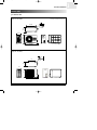
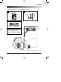
WALL MOUNTED TYPE
Manual
MODEL LINE-UP
SPECIFICATIONS
2
0
0
4
.
2
AIR CONDITIONER
1
7
OUTLINE & DIMENSION
11
PERFORMANCE DATA
17
INSTALLATION
27
FEATURES & OPERATION
45
DIAGRAM
63
TROUBLESHOOTING
75
DB98_16444A(1)_1
2/9/04 10:04 AM
Page 1
1
Model Line-Up
1-1. Model Identification
1-2. Model Line-Up
DB98_16444A(1)_1
2/9/04 10:04 AM
Page 2
DB98_16444A(1)_1
2/9/04 10:04 AM
Page 3
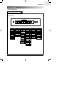
MODEL LINE-UP
Model Identification
1-1. Model Identification
Wall Mounted Type Air Conditioner
● Standard type
Model Code
Model Name
I
Q
V
09
A
1
M
E
!
@
#
$
%
^
&
*
$ Capacity
# Tech
Sub_Set
Set
A
None
Indoor
I
Tropical
T
Outdoor
X
INV+R22
V
R22+BLDC
D
Low Temp.
L
R407C
C
R410A
A
! Set Initial
Set
A
Indoor
A
Outdoor
U
@ Mode
H/P
Q
C/O
S
R410A+BLDC
^ Used
Btu
General
B
"30"
HP Mark
% Design of
Grille type
S/S Stand
/
A
Smile
B
C&C
C
V-Lip
D
G Premium
P
G-Deluxe
S
G-Deluxe
(K/L Grille)
K
Interior
I
GE
E
KLIMAT
Y
(
Buyer
& P/J Name
PD('00R)
1
PD_MR('00R)
MD('00R)
* Rating Voltage
V2
M
2
R
R
220V, 60Hz
B
3
T2
T
208~230V, 60Hz
C
MD_MR('00R)
4
Fashion
F
200~220V, 50Hz
D
PD2
5
V3
C
220~240V, 50Hz
E
PD2_MR
6
B
B
MD2
7
G
G
MD2_MR
8
Used
Q
PD3
9
Used
V
PD3_MR
0
Used
A
115V, 60Hz
A
( Serial Version
Basic
None
M/R
R
Specification change
^ Option
(Outdoor Sash)
Active
A
Active + MR
B
INV
C
C Specification+MR
D
Active2
E
G Mold
G
SAMSUNG | 3
1
DB98_16444A(1)_1
1
2/9/04 10:04 AM
Page 4
MODEL LINE-UP
Model Identification (cont.)
Wall Mounted Type Air Conditioner
● Separated type of export model for EU in private
Model Code
Model Name
! Products
Separated type
S
H
09
Z
A
1
!
@
#
$
%
^
# Capacity
S
@ Mode
% Design of
Grille type
Btu
S/S Standard
$ Tech
H/P
H
Normal
Z
C/O
C
Tropical
T
INV+R22
V
R22+BLDC
D
Lower temperature model
L
R407C
C
R410A
A
R410A+BLDC
B
X
&
/
*
(
^ Option
(Outdoor unit sash)
A
PD
1
Smile
B
PD_MR
2
C&C
C
MD
3
V-Lip
D
MD_MR
4
G Premium
P
PD2
5
G-Deluxe
S
PD2_MR
6
G-Deluxe
(K/L Grille)
K
Interior
Fashion
MD2
7
MD2_MR
8
I
PD3
9
F
PD3_MR
0
Active
A
GE
E
KLIMAT
Y
A Specification+MR B
INV(VSash)
C
C Specification+MR D
4 | SAMSUNG
G Mold
G
Active2
E
& Serial Version
Basic
None
Specification change A
* Half finished products
Indoor
None
Outdoor
X
( Secondary Specification
Division
Model for Western None
Europe
(EU)
Not used
XZE
Model for
Australia
XSA
DB98_16444A(1)_1
2/9/04 10:04 AM
Page 5
MODEL LINE-UP
Model Identification (cont.)
Piping(Parts Box)
Model Code
Model Name
! Piping Division
Initial
F
F
S
C
-
14
38
N
A
!
@
#
$
%
^
&
*
@ Products
# Mode
Export
RAC
S
Domestic
RAC
R
PAC
Common
$ Division
& Voltage type
H/P
H
Export
None
C/O
C
Domestic
-
P
H/P
H
Cassette
B
C/O
C
Duct
D
Oil
G
Ceiling
F
DPM
M
Export
Domestic
Multi
M
% High pressure pipe
Outer diameter
Export
None
Domestic
Indoor
N
Outdoor
X
* Version
1/4"
14
Basic
3/8"
38
New1
B
...
...
'01R Standard
Z
^ Low pressure
Outer diameter
1/2"
12
3/4"
34
3/8"
38
1"
44
5/8"
58
7/8"
78
1 1/8"
98
A
SAMSUNG | 5
1
DB98_16444A(1)_1
1
2/9/04 10:04 AM
Page 6
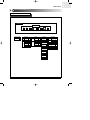
MODEL LINE-UP
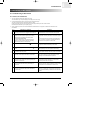
Model Line-Up
1-2. Model Line-Up (2004R)
Mode
Capacity
Indoor Unit
Outdoor Unit
7K
SH07APG
SH07APGX
Piping Unit
FSH1438Z
Mold
9K
SH09APG
SH09APGX
12K
SH12APG
SH12APGX
7K
SH07AS2
AQ07S2GE
SH07AS2X
UQ07S2GE
9K
SH09AS2
AQ09S2GB
AQ09S2GE
SH09AS2X
UQ09S2GB
UQ09S2GE
12K
SH12AS4
AQ12S4GB
AQ12S4GE
SH12AS4X
UQ12S4GB
UQ12S4GE
7K
SC07APG
SC07APGX
FSH1412Z
Heat Pump
FSH1438Z
Steel
FSH1412Z
FSC1438Z
Mold
9K
SC09APG
SC09APGX
12K
SC12APG
SC12APGX
7K
SC07AS2
AS07S2GE
SC07AS2X
US07S2GE
9K
SC09AS2
AS09S2GB
AS09S2GE
SC09AS2X
US09S2GB
US09S2GE
12K
SC12AS4
AS12S4GB
AS12S4GE
SC12AS4X
US12S4GB
US12S4GE
FSC1412Z
Cooling Only
FSC1438Z
Steel
6 | SAMSUNG
FSC1412Z
DB98_16444A(1)_1
2/9/04 10:04 AM
Page 7
2
Specifications
2-1. Table
DB98_16444A(1)_1
2/9/04 10:04 AM
Page 8
DB98_16444A(1)_1
2/9/04 10:04 AM
Page 9
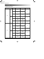
SPECIFICATIONS
Table
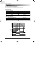
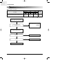
2-1. Table
Model
Item
SH07APG
Indoor unit
Type
SH09APG
Outdoor unit
Indoor unit
SH12APG
Outdoor unit
Indoor unit
Outdoor unit
Wall-mounted
Wall-mounted
Wall-mounted
2.47
2.70
3.50
2.46
2.90
3.80
0.9
1.4
1.9
Cooling
kW
Heating
|/h
Dehumidifying
Performance
Air Volume
Noise
3
m /min
6.5
dB
37
50
40
24
8.2
51
43
24
53
3.21
3.21
3.42
3.41
3.22
1-220 / 240-50
1-220 / 240-50
1-220 / 240-50
770
840
1,090
720
850
1,180
3.4
3.7
5.0
W/W
Heating
Power
V-Hz
Cooling
Power Consumption
W
Heating
Cooling
Operating Current
Power
7.0
3.21
Cooling
Energy Efficiency Ratio
24
A
Heating
3.3
3.7
5.2
Cooling
98.5
98.7
94.8
94.9
99.9
98.7
A
18.0
21.0
28.0
m
-
-
-
-
-
-
250V-10 / 16A
250V-10 / 16A
250V-10 / 16A
Power Factor
%
Heating
Starting Current
Length
Power Cord
Number of Core Wire
Capacity
Outer
Dimension
A
mm
795 x 258 x 179 695 x 530 x 280 795 x 258 x 179 695 x 530 x 280 890 x 285 x 179 695 x 530 x 280
inch
31.3 x 10.2 x 7.0 27.4 x 20.9 x 11.0 31.3 x 10.2 x 7.0 27.4 x 20.9 x 11.0 35.0 x 11.2 x 7.0 27.4 x 20.9 x 11.0
WxHxD
Weight
kg
7.5
26.5
7.5
27.0
8.5
34.0
Liquid
mm x L(m)
ø6.35 x 7.5
ø6.35 x 7.5
ø6.35 x 7.5
GAS
mm x L(m)
ø9.52 x 7.5
ø9.52 x 7.5
ø12.7 x 7.5
D x L(mm)
ø18 x 2,000
ø18 x 2,000
ø18 x 2,000
Rotary
Rotary
Rotary
Refrigerant Pipe
Size
Drain Hose
Type
Compressor
Type
-
-
-
-
-
-
Rated Output
-
-
-
-
-
-
Cross-fan
Propeller
Cross-fan
Propeller
Cross-fan
Propeller
steel
steel
steel
steel
steel
steel
11
25
11
25
15
25
Motor
Type
Blower
Type
Motor
Rated Output
W
2ROW 10STEP 1ROW 24STEP 2ROW 10STEP 1ROW 24STEP 2ROW 12STEP 2ROW 24STEP
Heat Exchanger
CAPILLARY TUBE
CAPILLARY TUBE
CAPILLARY TUBE
Freezer Oil Capacity
cc
350
280
500
Refrigerant to Change(R410A)
g
650
590
880
MRA99901-9201
RBC12054-12500
RBC12128-12500
Refrigerant Control Unit
Protection Device(OLP)
Cooling Test Condition
INDOOR UNIT : DB27˚C WB19˚C
OUTDOOR UNIT : DB35˚C WB24˚C
Maximum Operation Condition
INDOOR UNIT : DB32˚C WB23˚C
OUTDOOR UNIT : DB43˚C WB26˚C
SAMSUNG | 9
2
DB98_16444A(1)_1
2
2/9/04 10:04 AM
Page 10
SPECIFICATIONS
Table (cont.)
Table(cont.)
Model
Item
SH07AS2
Indoor unit
Type
SH09AS2
Outdoor unit
Indoor unit
SH12AS4
Outdoor unit
Indoor unit
Outdoor unit
Wall-mounted
Wall-mounted
Wall-mounted
2.30
2.70
3.50
2.40
2.90
3.80
0.9
1.4
1.9
Cooling
kW
Heating
|/h
Dehumidifying
Performance
Air Volume
Noise
3
m /min
6.2
22
6.8
22
8.2
24
dB
36
50
39
51
43
53
2.95
2.87
2.82
3.24
3.22
3.22
1-220 / 240-50
1-220 / 240-50
1-220 / 240-50
780
940
1,240
740
900
1,180
3.5
4.2
5.4
Cooling
Energy Efficiency Ratio
W/W
Heating
Power
V-Hz
Cooling
Power Consumption
W
Heating
Cooling
Operating Current
Power
A
Heating
3.3
4.0
5.2
Cooling
96.9
97.3
99.8
97.5
97.8
98.7
A
17.0
21.0
32.0
m
-
-
-
-
-
-
250V-10 / 16A
250V-10 / 16A
250V-10 / 16A
Power Factor
%
Heating
Starting Current
Length
Power Cord
Number of Core Wire
Capacity
Outer
Dimension
A
mm
795x258x179
660x495x235
795x258x179
660x495x235
890x285x179
inch
31.3x10.2x7.0
26.0x19.5x9.3
31.3x10.2x7.0
26.0x19.5x9.3
35.0x11.2x7.0 28.3x20.9x10.2
kg
7.5
26.0
7.5
26.5
720x530x260
WxHxD
Weight
8.5
33.0
Liquid
mm x L(m)
ø6.35 x 7.5
ø6.35 x 7.5
ø6.35 x 7.5
GAS
mm x L(m)
ø9.52 x 7.5
ø9.52 x 7.5
ø12.7 x 7.5
D x L(mm)
ø18 x 2,000
ø18 x 2,000
ø18 x 2,000
Rotary
Rotary
Rotary
Refrigerant Pipe
Drain Hose
Size
Type
Compressor
-
Type
-
-
-
-
-
Motor
Rated Output
Type
Blower
Type
-
-
-
-
-
-
Cross-flow
Propeller
Cross-flow
Propeller
Cross-flow
Propeller
steel
steel
steel
steel
steel
steel
11
20
11
20
15
25
Motor
Rated Output
W
2ROW 10STEP 1ROW 22STEP 2ROW 10STEP 1ROW 22STEP 2ROW 12STEP 1ROW 24STEP
Heat Exchanger
Refrigerant Control Unit
CAPILLARY TUBE
CAPILLARY TUBE
CAPILLARY TUBE
Freezer Oil Capacity
cc
350
280
500
Refrigerant to Change(R410A)
g
600
500
750
MRA99901-9201
RBC12131-12500
RBC12128-12500
Protection Device(OLP)
Cooling Test Condition
INDOOR UNIT : DB27˚C WB19˚C
OUTDOOR UNIT : DB35˚C WB24˚C
Maximum Operation Condition
INDOOR UNIT : DB32˚C WB23˚C
OUTDOOR UNIT : DB43˚C WB26˚C
10 | SAMSUNG
DB98_16444A(1)_1
2/9/04 10:04 AM
Page 11
3
Outline & Dimension
3-1. Indoor Unit
3-2. Outdoor Unit
DB98_16444A(1)_1
2/9/04 10:04 AM
Page 12
DB98_16444A(1)_1
2/9/04 10:04 AM
Page 13
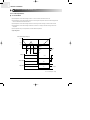
OUTLINE & DIMENSION
Indoor Unit
3-1. Indoor Unit(PREMIUM)
(Front view)
Air in
C
B
Air out
(Remote control)
16
150
A
(Rear view)
24
53
(Installation plate)
60
12K
60
7K/9K
252
275
100
45
275
19
252
158
90
Type
A
B
C
7K / 9K
795
258
179
12K
890
285
179
165
SAMSUNG | 13
3
DB98_16444A(1)_1
Page 14
OUTLINE & DIMENSION
Indoor Unit (cont.)
Indoor Unit(DELUXE)
(Front view)
Air in
C
B
Air out
(Remote control)
115
A
(Rear view)
22
45
(Installation plate)
12K
60
7K/9K
60
275
252
275
100
158
90
Type
14 | SAMSUNG
45
252
19
3
2/9/04 10:04 AM
A
B
C
7K / 9K
795
258
179
12K
890
285
179
165
DB98_16444A(1)_1
2/9/04 10:04 AM
Page 15
OUTLINE & DIMENSION
Outdoor Unit
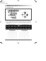
3-2. Outdoor Unit
✳ The figure in parentheses means 12K.
■ 7K / 9K / 12K (STEEL)
13
504(550)
28
258
(276)
235(260)
495
(530)
660(720)
42(46)
■ 7K / 9K / 12K (MOLD)
11
20
489
300
280
530
695
60
SAMSUNG | 15
3
DB98_16444A(1)_1
2/9/04 10:04 AM
Page 16
MEMO
16 | SAMSUNG
DB98_16444A(1)_1
2/9/04 10:04 AM
Page 17
4
Performance Data
4-1. Performance Data
SAMSUNG | 17
DB98_16444A(1)_1
2/9/04 10:04 AM
18 | SAMSUNG
Page 18
DB98_16444A(1)_1
2/9/04 10:04 AM
Page 19
PERFORMANCE DATA
Performance Data
4-1. Performance Data
4-1-1. Capacity
● 7,000BTU
■ Capacity Distribution
<Cooling>
3.0
DB32.4/WB24.0
DB30.6/WB22.5
DB27.0/WB19.0
DB24.0/WB17.0
DB21.5/WB15.0
2.0
1.0
4.5
Indoor Temp.
25
35
Heating Capacity(kW)
Cooling Capacity(kW)
4.0
<Heating>
3.5
DB15.0
DB20.0
DB25.0
2.5
1.5
1.0/0.0
45
Indoor Temp.
Outdoor Temp.(DB C)
7.0/6.0
20.0/15.0
Outdoor Temp.(DB/WB C)
■ Power consumption Distribution
<Cooling>
<Heating>
Indoor Temp.
1100.0
DB32.4/WB24.0
DB30.6/WB22.5
DB27.0/WB19.0
DB24.0/WB17.0
DB21.5/WB15.0
900.0
700.0
25
35
Outdoor Temp.(DB C)
45
Power consumption(W)
Power consumption(W)
Indoor Temp.
DB25.0
900
DB20.0
DB15.0
700
500
1.0/0.0
7.0/6.0
20.0/15.0
Outdoor Temp.(DB/WB C)
SAMSUNG | 19
14
DB98_16444A(1)_1
Page 20
PERFORMANCE DATA
Performance Data (cont.)
Capacity (cont.)
● 9,000BTU
■ Capacity Distribution
<Cooling>
<Heating>
Indoor Temp.
3.0
DB32.4/WB24.0
DB30.6/WB22.5
2.0
DB27.0/WB19.0
DB24.0/WB17.0
DB21.5/WB15.0
Heating Capacity(kW)
Cooling Capacity(kW)
4.0
1.0
25
35
4.5
Indoor Temp.
3.5
DB15.0
DB20.0
DB25.0
2.5
1.5
1.0/0.0
45
7.0/6.0
20.0/15.0
Outdoor Temp.(DB/WB C)
Outdoor Temp.(DB C)
■ Power consumption Distribution
<Cooling>
<Heating>
Indoor Temp.
1100.0
DB32.4/WB24.0
DB30.6/WB22.5
DB27.0/WB19.0
DB24.0/WB17.0
DB21.5/WB15.0
900.0
700.0
25
35
Outdoor Temp.(DB C)
20 | SAMSUNG
45
Indoor Temp.
Power consumption(W)
Power consumption(W)
4
2/9/04 10:04 AM
1000
DB25.0
DB20.0
DB15.0
800
600
1.0/0.0
7.0/6.0
Outdoor Temp.(DB/WB C)
20.0/15.0
DB98_16444A(1)_1
2/9/04 10:04 AM
Page 21
PERFORMANCE DATA
Performance Data (cont.)
Capacity (cont.)
● 12,000BTU
■ Capacity Distribution
<Cooling>
5.5
Indoor Temp.
4.0
DB32.4/WB24.0
DB30.6/WB22.5
3.0
DB27.0/WB19.0
DB24.0/WB17.0
DB21.5/WB15.0
Heat Capacity(kW)
Cooling Capacity(kW)
5.0
<Heating>
Indoor Temp.
DB15.0
DB20.0
DB25.0
4.5
3.5
2.0
2.5
35
25
45
1.0/0.0
Outdoor Temp.(DB C)
7.0/6.0
20.0/15.0
Outdoor Temp.(DB/WB C)
■ Power consumption Distribution
<Cooling>
1600
Indoor Temp.
DB32.4/WB24.0
DB30.6/WB22.5
DB27.0/WB19.0
DB24.0/WB17.0
DB21.5/WB15.0
1400
1200
1000
Power consumption(W)
Power consumption(W)
1600
<Heating>
Indoor Temp.
DB25.0
1400
DB20.0
DB15.0
1200
1000
25
35
Outdoor Temp.(DB C)
45
1.0/0.0
7.0/6.0
20.0/15.0
Outdoor Temp.(DB/WB C)
SAMSUNG | 21
41
DB98_16444A(1)_1
Page 22
PERFORMANCE DATA
Performance Data (cont.)
4-1-2. C00ling Capacity Correction Factors
● 7,000BTU
2590.4
2467.0
Capacity(W)
2343.7
2220.3
2097.0
1973.6
1850.3
1726.9
7.5
15.0
Piping Length(m)
847.6
831.0
814.4
797.8
781.1
Input(W)
4
2/9/04 10:04 AM
764.5
747.9
731.3
714.7
698.0
7.5
15.0
Piping Length(m)
22 | SAMSUNG
DB98_16444A(1)_1
2/9/04 10:04 AM
Page 23
PERFORMANCE DATA
Performance Data (cont.)
C00ling Capacity Correction Factors(cont.)
● 9,000BTU
2650
2600
2550
Capacity(W)
2500
2450
2400
2350
2300
2250
2200
7.5
15.0
Piping Length(m)
898.5
898.0
897.5
897.0
Input(W)
896.5
896.0
895.5
895.0
894.5
894.0
893.5
7.5
15.0
Piping Length(m)
SAMSUNG | 23
4
DB98_16444A(1)_1
Page 24
PERFORMANCE DATA
Performance Data (cont.)
C00ling Capacity Correction Factors(cont.)
● 12,000BTU
3550.0
3500.0
Capacity(W)
3450.0
3400.0
3350.0
3300.0
3250.0
7.5
15
Piping Length(m)
1185
1180
1175
Input(W)
4
2/9/04 10:04 AM
1170
1165
1160
1155
7.5
15
Piping Length(m)
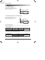
✳Refrigerant must be added if the piping length is more than 7.5metres.
✳In case of 7K and 9K models, 20g of refrigerant 'R410A' must be added for each extra metre.
✳In case of 12K model, 30g of refrigerant 'R410A' must be added for each extra metre.
24 | SAMSUNG
DB98_16444A(1)_1
2/9/04 10:04 AM
Page 25
PERFORMANCE DATA
Performance Data (cont.)
4-1-3. Low Pressure Distribution(Cooling Mode)
Low pressure(kg/cm G)
● 7,000BTU
12.0
Indoor Temp.
DB32.4/WB24.0
DB30.6/WB22.5
10.0
DB27.0/WB19.0
DB24.0/WB17.0
DB21.5/WB15.0
8.0
6.0
25
35
45
Outdoor Temp.(DB C)
● 9,000BTU
Low pressure(kg/cm G)
12.0
Indoor Temp.
DB32.4/WB24.0
DB30.6/WB22.5
10.0
DB27.0/WB19.0
DB24.0/WB17.0
DB21.5/WB15.0
8.0
6.0
25
35
45
Outdoor Temp.(DB C)
Low pressure(kg/cm G)
● 12,000BTU
12.0
Indoor Temp.
10.0
DB32.4/WB24.0
DB30.6/WB22.5
DB27.0/WB19.0
DB24.0/WB17.0
DB21.5/WB15.0
8.0
6.0
25
35
45
Outdoor Temp.(DB C)
SAMSUNG | 25
4
DB98_16444A(1)_1
2/9/04 10:04 AM
Page 26
MEMO
26 | SAMSUNG
DB98_16444A(1)_1
2/9/04 10:04 AM
Page 27
5
Installation
5-1. Selecting Area for Installation
5-2. Installation Diagram of Indoor Unit and Outdoor Unit
5-3. Performing Leak Tests
5-4. Placing the Indoor Unit in Position
5-5. Checking and Testing Operations
DB98_16444A(1)_1
2/9/04 10:04 AM
Page 28
DB98_16444A(1)_1
2/9/04 10:04 AM
Page 29
INSTALLATION
Selecting Area for Installation
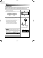
Select an area for installation that is suitable to customer’s needs.
5-1. Selecting Area for Installation
5-1-1. Indoor Unit
1. Make sure that you install the indoor unit in an area providing good ventilation.
It must not be blocked by an obstacle affecting the airflow near the air inlet and the air outlet.
2. Make sure that you install the indoor unit in an area allowing good air handling and endurance of vibration of the indoor unit.
3. Make sure that you install the indoor unit in an area where there is no source of heat or vapor nearby.
4. Make sure that you install the indoor unit in an area from which hot or cool air is spread evenly in a room.
5. Make sure that you install the indoor unit in an area away from TVs, audio units, cordless phones, fluorescent lighting fixtures and other
electrical appliances (at least 1 meter).
6. Make sure that you install the indoor unit in an area which provides easy pipe connection with the outdoor unit, and easy drainage for
condensed water.
7. Make sure that you install the indoor unit in an area which is large enough to accommodate the measurements shown in figure on the
next page.
CAUTION
• It is harmful to the air conditioner if it is used in the following environments: greasy areas (including areas near
machines), salty areas such as coast areas, areas where sulfuric gas is present such as hot spring areas.
Contact your dealer for advice.
SAMSUNG | 29
5
DB98_16444A(1)_1
5
2/9/04 10:04 AM
Page 30
INSTALLATION
Selecting Area for Installation (cont.)
5-1-2. Outdoor Unit
1. Make sure that you install the outdoor unit in area not exposed to the rain or direct sun light.(Install a separate sunblind if exposed to
direct sun light.)
2. Make sure that you install the outdoor unit in area allowing the good air moment, not amplifying noise or vibration, especially to avoid
disturbing neighbors. (Fix the unit firmly if it is mounted in a high place.)
3. Make sure that you install the outdoor unit in area providing the good ventilation and which is not dusty. It must not be blocked by any
obstacle affecting the airflow near the air inlet and the air outlet.
4. Make sure that you install the outdoor unit in area free from animals or plants.
5. Make sure that you install the outdoor unit in area not blocking the traffic.
6. Make sure that you install the outdoor unit in area easy to drain condensed water from the indoor unit.
7. Make sure that you install the outdoor unit in area which provides easy connection within the maximum allowable length of a coolant
pipe.
If you have used...
Then...
More than "A" metres of
piping
"B"g of refrigerant (R410A)
must be added for each
extra meter.
Less than "A" metres
of piping
The purge time is normal.
MODEL
A
B
SH07 / 09A✳✳
7.5
20
SH12A✳✳
7.5
30
8. Make sure that you install the outdoor unit in an area which is large enough to accommodate the measurements shown in figure on the
next page.
5-1-3. Remote Control Unit
1. Make sure that you use the remote control unit in an area free from obstacles such as curtains etc, which may block signals from the
remote control unit.
2. Make sure that you put the remote control unit in an area not exposed to direct sunlight, and where there is no source of heat.
3. Make sure that you use the remote control unit in an area away from TVs, audio units, cordless phones, fluorescent lighting fixtures and
other electrical appliances (at least 1 meter).
30 | SAMSUNG
DB98_16444A(1)_1
2/9/04 10:04 AM
Page 31
INSTALLATION
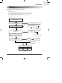
Installation Diagram of Indoor Unit and Outdoor Unit
5-2. Installation Diagram of Indoor Unit and Outdoor Unit
A
B
Indoor unit gas leak test
Drain hose installation
Cut the piping hole
sloped
Cut theslightly
piping hole
3
Indoor unit
sloped slightly
1
Piping
Vinyl tape
2
Piping may be laid to the rear, left, right or down.
Left
Right
Rear
Rear
• Wrap the refrigerant pipes and the drain hose up
in the absorbent pad and the vinyl tape.
300 mm or more
125 mm
or more
125 mm
or more
• Triply wind the pipes and hose to the end of the
indoor unit with the absorbent pad (make intervals
of 20mm)
7metres maximum
600 mm
minimum
15metres
maximum
300 mm
minimum
300 mm
minimum
600 mm
minimum
* The designs of the unit and Connection value are
subject to Change according to the model.
SAMSUNG | 31
5
DB98_16444A(1)_1
Page 32
INSTALLATION
Installation Diagram of Indoor Unit and Outdoor Unit (cont.)
5-2-1. Fixing the Installation Plate
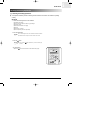
1. Determine the position of the pipe and drain hose hole
referring to the right figure and drill the hole with an inner diameter of 65mm so
that it slants slightly downwards.
Pipe hole
(Ø65mm)
2. If you are fixing the indoor unit to a… Then follow Steps…
3.
Window frame
4 to 6.
3. Fix the installation plate to the wall in a manner
appropriate to the weight of the indoor unit.
7K/9K
(Unit : mm)
60
Wall
30mm
Installation plate
252
275
19
If you are mounting the plate on a concrete wall with anchor bolts,
anchor bolts must not be projected by more than 20mm.
100
4. Determine the position of the wooden uprights to be attached to the window
frame.
158
12K
60
5. Attach the wooden upright to the window frame in a manner appropriate to the
weight of the indoor unit.
252
275
45
5
2/9/04 10:04 AM
6. Using tapped screws, attach the installation plate to the wooden upright,
as illustrated in the last figure opposite.
90
165
5-2-2. Purging the Unit
On delivery, the indoor unit is loaded with an inert gas. All this gas must therefore be purged before connecting the assembly
piping. To purge the inert gas, proceed as follows.
Unscrew the cap at the end of each pipe.
Result All inert gas escapes from the indoor unit.
◆ To prevent dirt or foreign objects from getting into the pipes during installation,
do NOT remove caps completely until you are ready to connect the piping.
32 | SAMSUNG
DB98_16444A(1)_1
2/9/04 10:04 AM
Page 33
INSTALLATION
Installation Diagram of Indoor Unit and Outdoor Unit (cont.)
5-2-3. Connecting the Assembly Cable (Cooling Only)
The outdoor unit is powered from the indoor unit via the assembly cable. (7K/9K/12K)
1. Extend the assembly cable if necessary.
2. Open the front grille by pulling on the tab on the lower right and left sides of the
indoor unit.
3. Remove the screw securing the connector cover.
4. Pass the assembly cable through the rear of the indoor unit and connect the assembly
cable to terminals.
◆ Each wire is labeled with the corresponding terminal number.
Indoor
N(1) 1
unit
5. Firmly fix the ass'y cable with clamp wire holder.
E
N1
11N
E
N1
1
6. Pass the other end of the cable through the 65mm hole in the wall.
7. Replace the connector cover, carefully tightening the screw.
Outdoor
N(1) 1
unit
8. Close the front grille.
2
3
9. For further details on how to plug the other end of the assembly cable into the
outdoor unit.
5-2-4. Connecting the Assembly Cable (Heat Pump)
The outdoor unit is powered from the indoor unit via the assembly cable. (7K/9K/12K)
1. Extend the assembly cable if necessary.
2. Open the front grille by pulling on the tabs on the lower right and left sides of the
indoor unit.
3. Remove the screw securing the connector cover.
4. Pass the assembly cable through the rear of the indoor unit and connect the
assembly cable to terminals.
◆ Each wire is labeled with the corresponding terminal number.
5. Pass the other end of the cable through the 65 mm hole in the wall.
Indoor
unit
N(1) 1
2
3
N1
1
2
3
E
N1
1
2
3
E
N(1) 1
2
3
Outdoor
unit
6. Replace the connector cover, carefully tightening the screw.
7. Close the front grille.
8. For further details on how to plug the other end of the assembly cable into the
outdoor unit.
SAMSUNG | 33
5
DB98_16444A(1)_1
5
2/9/04 10:04 AM
Page 34
INSTALLATION
Installation Diagram of Indoor Unit and Outdoor Unit (cont.)
5-2-5. Installing and Connecting the Indoor Unit Drain Hose
Care must be taken when installing the drain hose for the indoor unit to ensure that any condensed water is correctly drained outside. When passing the drain hose through the 65mm hole drilled in the wall, check that none of the following situation occur.
5cm less
The hose must
NOT slope
upwards.
The end of the drain
hose must NOT be
placed in water.
Do NOT bend the
hose in different
directions.
Keep a clearance of at
least 5cm between the
end of the hose and the
ground.
Do NOT place the
end of the drain hose
in a hollow.
To install the drain hose, proceed as follows
1. If necessary, connect the 2-meter extension to the drain hose.
Shield
2. If you are using the extension, insulate the inside part of the extension
drain hose with a shield.
3. Pass the drain hose under the refrigerant piping, taking care to keep the
drain hose tight.
4. Pass the drain hose through the hole in the wall, making sure that it is
sloping downwards, as shown in the illustrations above.
34 | SAMSUNG
Drain hose
Extension drain hose
The hose will be fixed permanently into
position once the whole installation has been
tested for gas leaks.
DB98_16444A(1)_1
2/9/04 10:04 AM
Page 35
INSTALLATION
Installation Diagram of Indoor Unit and Outdoor Unit (cont.)
5-2-6. Flare Modification
● TOOLS USED
● FLARE MODIFICATION PROCEDURE
1. Cut the pipe using a pipe cutter.
Oblique
90
2. Remove burrs at the tip of the pipe cut.
Roughness
Burr
Pipe
Reamer
CAUTION
• Burrs not removed may result in leakage of gas.
3. Insert a flare nut into the pipe and modify flare.
* Unproper flaring
D
A
Outer diameter
A(mm)
ø6.35mm
1.3
ø9.52mm
1.8
ø12.7mm
2.0
Inclined
Surface
damaged
Cracked
Uneven
thickness
SAMSUNG | 35
5
DB98_16444A(1)_1
5
2/9/04 10:04 AM
Page 36
INSTALLATION
Installation Diagram of Indoor Unit and Outdoor Unit (cont.)
5-2-7. Air-Purge Procedure
The outdoor unit is loaded with sufficient R22 refrigerant for 5 metres of piping. The air in the indoor unit and in the pipe must be
purged. If air remains in the refrigeration pipes, it will affect the compressor, reduce to cooling/heating capacity and could lead to
a malfunction. Refrigerant for air purging is not charged in the outdoor unit. Use Vacuum Pump as shown at the figure.
1. Connect each assembly pipe to the appropriate valve on
the outdoor unit and tighten the flare nut.
2. Referring to the illustration opposite, tighten the flare nut first manually and then
with a wrench, applying the following torque.
Outer Diameter
Torque(kg.cm)
6.35mm
140~170
9.52mm
250~280
12.70mm
380~420
Outdoor unit
A
B
Indoor unit
Gas pipe side C
Liquid pipe side
D
3. Connect the charging hose of low pressure side of manifold gauge to the packed
valve having a service port as shown at the figure.
4. Open the valve of the low pressure side of manifold gauge counterclockwise.
5. Purge the air from the system using vacuum pump for about 10 minutes.
◆ Close the valve of the low pressure side of manifold gauge
clockwise.
◆ Make sure that pressure gauge show -0.1MPa(-76cmHg)
after about 10minutes.
This procedure is very important in order to avoid gas leak.
◆ Turn off the vacuum pump
◆ Remove the hose of the low pressure side of manifold gauge.
Vacuum
Pump
* The designs and shape are subject to
change according to the model.
Adding Refrigerant
Refrigerant must be added if the piping measures more than 7.5 metres in length.
This operation can only be performed by a qualified refrigeration specialist.
If you have used...
Then...
More than "A" metres
of piping
"B" of refrigerant (R410A)
must be added for each
extra meter.
Less than "A" metres
of piping
The purge time is normal.
Refer to the Service Manual for more details on this operation.
36 | SAMSUNG
MODEL
A
B
SH07/09A✴✴
7.5
20
SH12A✴✴
7.5
30
DB98_16444A(1)_1
2/9/04 10:04 AM
Page 37
INSTALLATION
Installation Diagram of Indoor Unit and Outdoor Unit (cont.)
6. Set valve cork of both liquid side and gas side of packed valve to the open
position.
7. Mount the valve stem nuts and the service port cap to the valve, and tighten
them at the torque of 183kgf.cm with a torque wrench.
8. Check for gas leakage.
◆ At this time, especially check for gas leakage from 3-Way valve’s stem nuts,
and from the service port cap.
A
(gas)
B
(liquid)
Valve stem
Stem cap
SAMSUNG | 37
5
DB98_16444A(1)_1
5
2/9/04 10:04 AM
Page 38
INSTALLATION
Installation Diagram of Indoor Unit and Outdoor Unit (cont.)
5-2-8. Refrigerant Refill
● Refill an air-conditioner with refrigerant when refrigerant has been leaked at installing or using.
1
Purge air(for new installation only).
▼
2
Turn the 3-Way valve clockwise to close,
connect the pressure gauge (low pressure side)
to the service valve, and open the 3-Way
valve again.
▼
3
Suspension hook
Compound
gauge
Connect the tank to refill with refrigerant
Hand
wheel
▼
4
Set the unit to cool operation mode.
▼
5
Check the pressure indicated by the pressure
gauge(low pressure side).
* Standard pressure should be 4.5~5.5kg/cm2
in a regular and high operation mode.
▼
Open the refrigerant tank and fill with refrigerant
until the rated pressure is reached.
6
* It is recommended not to pour the refrigerant in
too quickly, but gradually while operating a pressure valve.
▼
7
Stop operation of the air conditioner.
▼
8
Close the 3-Way valve, disconnect the pressure
gauge, and open the 3-Way valve again.
▼
9
High
pressure
gauge
Close the cap of each valve.
38 | SAMSUNG
Finger tight
fittings
For mounting
other and of
hose when
not in use
Connected to
high pressure
side
Charging line
DB98_16444A(1)_1
2/9/04 10:04 AM
Page 39
INSTALLATION
Installation Diagram of Indoor Unit and Outdoor Unit (cont.)
5-2-9. Refrigerant Adjustment
Class
At installation
Connection
Pipe Length
Standard
7.5m
At service
Air-Purge
Method
Refrigerant
Adjustment
Refer to the
detailed Air-Purge
Procedure
Unnecessary
Air-Purge
Method
Refrigerant
Quantity
Purge air using a
vacuum pump
or an additional
refrigerant cylinder.
Add "A" of refrigerant
(R410A) for every 1m.
Max.
~15m
refer to
specification sheet
Add "A" of refrigerant
(R410A) for every 1m.
It would be the best choice to use the standard tube length to keep the basic
quality of Room Air conditioner, for example cooling and heating capacity, sound level,
vibration level, and reliability.
But, according to a certain different installation condition, the connection
tube length could be changed in the recommendation length that is shown above.
In this case, installer should keep the installation condition to keep the quality of Room Air
conditioner.
MODEL
"A"
"B"
7K/ 9K
20(g/m)
7.5
12K
30(g/m)
7.5
❇ Refrigerant should be charged additionally as written above according to the change of the length of the connection tube.
It needs to affect the decrease in cooling and heating capacity or of the reliability of compressor that may be caused by a lack of
refrigerant.
❇ Installation position difference between the indoor unit and the outdoor unit should not exceed over than “B” meters.
❇ When the connection pipe is been extended longer than 7.5 meters, it might need to change the diameter of the
electrical wire to a larger size in order to keep a voltage drop for starting room air conditioner is not less
than 85% of the rated voltage. And then, a voltage meter will be useful to check the rate of the voltage drop.
5-2-10. Flare Nut Fixing Torque
Torque (kg-cm)
Outer diameter
Fixing Torque
Final Torque
ø 6.35 mm
(Liquid Side)
160
200
ø 9.52 mm
(Gas Side)
300
350
ø 12.7 mm
(Gas Side)
500
550
SAMSUNG | 39
5
DB98_16444A(1)_1
5
2/9/04 10:04 AM
Page 40
INSTALLATION
Installation Diagram of Indoor Unit and Outdoor Unit (cont.)
5-2-11. "Pump down" Procedure
Pump down will be carried out when an evaporator is replaced or when the unit is relocated in another area.
1
Remove the caps from the 2-Way valve and the
3-Way valve.
▼
2
Turn the 3-Way valve clockwise to close and
connect a pressure gauge (low pressure side)
to the service valve, and open the 3-Way valve
again.
▼
3
Set the unit to cool operation mode.
(Check if the compressor is operating.)
3-Way Valve
▼
4
Turn the 2-Way valve clockwise to close.
2-Way Valve
▼
5
When the pressure gauge indicates "0" turn the
3-Way valve clockwise to close.
▼
6
Stop operation of the air conditioner.
▼
7
Close the cap of each valve.
Relocation of the Air Conditioner
• Refer to this procedure when the unit is relocated.
1. Carry out the pump down procedure (refer to the details of 'pump down').
2. Remove the power cord.
3. Disconnect the assembly cable from the indoor and outdoor units.
4. Remove the flare nut connecting the indoor unit and the pipe.
At this time, cover the pipe of the indoor unit and the other pipe using a cap or vinyl plug to avoid foreign material entering.
5. Disconnect the pipe connected to the outdoor unit.
At this time, cover the valve of the outdoor unit and the other pipe using a cap or vinyl plug to avoid foreign material entering.
6. Make sure you do not bend the connection pipes in the middle and store together with
the cables.
7. Move the indoor and outdoor units to a new location.
8. Remove the mounting plate for the indoor unit and move it to a new location.
40 | SAMSUNG
DB98_16444A(1)_1
2/9/04 10:04 AM
Page 41
INSTALLATION
Performing Leak Tests
5-3. Performing Leak Tests
●
Before completing the installation (insulation of the cable, hose and piping and fixing of the indoor unit to the
installation plate), you must check that there are no gas leaks.
To check for gas leaks on the...
Then, using a leak detector,
check the...
Indoor unit
Flare nuts at the end of sections
C and D.
Outdoor unit
Valves on sections A and B.
C
D
A
B
❊ The designs and shape are subject to
change according to the model.
SAMSUNG | 41
5
DB98_16444A(1)_1
5
2/9/04 10:04 AM
Page 42
INSTALLATION
Placing the Indoor Unit in Position
5-4. Placing the Indoor Unit in Position
●
Once you have checked that there are no leaks in the system, you can insulate the piping, hose and cables and place
the indoor unit on the installation plate.
1. To avoid condensation problems, place heat-resistant polyethylene foam
separately around each refrigerant pipe in the lower part of the indoor unit.
2. Wind insulating tape around the pipe, assembly cable and drain hose.
3. Place the resulting bundle carefully in the lower part of the indoor unit,
making sure that it does not jut out from the rear of the indoor unit.
4. Hook the indoor unit up to the installation plate and move the unit to the
right and left until you are sure that it is securely to place in.
5. Finish wrapping insulating tape around the rest of the piping leading
to the outdoor unit.
6. Using clamps (optionally supplied), attach the piping to the wall
wherever possible.
42 | SAMSUNG
Installation
plate
DB98_16444A(1)_1
2/9/04 10:04 AM
Page 43
INSTALLATION
Checking and Testing Operations
5-5. Checking and Testing Operations
●
To complete the installation, perform the following checks and tests to ensure that the air conditioner is operating
correctly.
■ PREMIUM
1. Review all the following elements in the installation:
◆ Installation site strength
◆ Piping connection tightness to detect any gas leakages
◆ Connection wiring
◆ Heat-resistant insulation of the piping
◆ Drainage
◆ Earthing wire connection
◆ Correct operations (follow the steps below)
2. Press the On/Off button.
Result
◆ The indicator lights on the indoor unit flash at half-second intervals.
◆ While the indoor unit opens, the indoor unit fan runs to start.
3. Press the
Result
button.
◆ If you press the
you want.
button several times, you can choose the type
4. Air flow direction
◆ Press the
button and check that the air flow blades work properly.
SAMSUNG | 43
5
DB98_16444A(1)_1
5
2/9/04 10:04 AM
Page 44
INSTALLATION
Checking and Testing Operations (cont.)
■ DELUXE
1. Review all the following elements in the installation:
◆ Installation site strength
◆ Piping connection tightness to detect any gas leakages
◆ Connection wiring
◆ Heat-resistant insulation of the piping
◆ Drainage
◆ Earthing wire connection
◆ Correct operations (follow the steps below)
2. Press the On/Off button.
Result
◆ The indicator lights on the indoor unit flash at half-second intervals.
◆ While the indoor unit opens, the indoor unit fan runs to start.
3. Press the
Result
button.
◆ The temperature and fan settings are adjusted automatically.
◆ If you press the
button one or more times until
or
disappears,
the air conditioner is reset automatically to the previous mode, temperature
and fan settings.
4. Air flow direction
◆ Press the
44 | SAMSUNG
button and check that the air flow blades work properly.
DB98_16444A(1)_1
2/9/04 10:04 AM
Page 45
6
Features & Operation
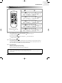
6-1. The Feature of key in Remote Control
6-2. Details for Operation Property
6-3. Operating Recommendations
6-4. Temperature and Humidity Ranges
DB98_16444A(1)_1
2/9/04 10:04 AM
Page 46
DB98_16444A(1)_1
2/9/04 10:04 AM
Page 47
FEATURES & OPERATION
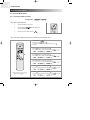
The Feature of key in Remote Control
6-1. The Feature of key in Remote Control
6-1-1. S✳07APG / S✳09APG / S✳12APG
No
1
FUNCTION OF KEY
NAMED OF KEY
(On/Off)
(On/Off)
On/Off button.
Press the
button to stop or run the air conditioner.
(UP)
Temperature adjustment button(UP).
To increase the temperature by the pressing the temperature button.
(DOWN)
Temperature adjustment button(DOWN).
To decrease the temperature by the pressing the temperature button.
2
3
Mode selection button.
Each time you press this button
Mode is changed in the following order
: Auto Mode
: Fan Only
: Cool Mode
: Heat Mode
: Dry Mode
Fan speed adjustment button.
Each time you press this button, FAN SPEED is changed in the following order.
4
Low
Medium
High
Automatic(rotated :
)
5
Swing button.
It adjusts the airflow to upward and downward.
6
Turbo button.
The air conditioner cools or heats the room as quickly as possible.
After 30minutes, the air conditioner is reset automatically to the previous mode.
7
Energy saving button.
If you wish to save energy when using your air conditioner, select the Energy saving
mode with the
button.
8
Sleep button.
The sleep timer can be used when you are cooling or heating your room to switch the
air conditioner off automatically after a period of six hours.
SAMSUNG | 47
6
DB98_16444A(1)_1
6
2/9/04 10:04 AM
Page 48
FEATURES & OPERATION
The Feature of key of Remote Control (cont.)
The Feature of key in Remote Control (cont.)
No
NAMED OF KEY
9
10
FUNCTION OF KEY
Anion button.
Press the
button to generate ion from the air conditioner.
On Timer button.
The On Timer enables you to switch on the air conditioner automatically after
a given period of time that is from 30 minutes to 24 hours.
To set the operating time, press the
time display.
11
Off Timer button.
The Off Timer enables you to switch off the air conditioner automatically after
a given period of time that is from 30 minutes to 24 hours.
To set the operating time, press the
time display.
12
48 | SAMSUNG
button one or more times until the required
Timer Set/Cancel button.
After setting On Timer or Off Timer, press the
And press the
13
button one or more times until the required
button to set it completely.
button again to cancel On Timer or Off Timer set.
Digital On/Off button.
If you want to turn off the display during operation press the
button.
DB98_16444A(1)_1
2/9/04 10:04 AM
Page 49
FEATURES & OPERATION
The Feature of key of Remote Control (cont.)
6-1-2. S✳07AS2 / S✳09AS2 / S✳12AS4
No
NAMED OF KEY
FUNCTION OF KEY
1
On/Off & Timer Set/Cancel button.
Press the
button to stop and run the air conditioner or On/Off timer set up.
2
Mode selection button.
Each time you press this button,
Mode is changed in the following order.
: Auto Mode
: Fan Only
: Cool Mode
: Heat Mode
: Dry Mode
(UP)
Temperature adjustment button(UP).
To increase the temperature by the pressing the temperature button.
(DOWN)
Temperature adjustment button(DOWN).
To decrease the temperature by the pressing the temperature button.
3
Turbo/Sleep mode selection button.
Press the
button one or more times until
appears. The air conditioner cools or
heats the room as quickly as possible. After 30minutes, the air conditioner is reset automatically
to the previous mode.
4
Turbo/Sleep mode selection button.
Press the
button one or more times until
appears. The sleep timer can be used
when you are cooling or heating your room to switch the air conditioner off
automatically after a period of six hours.
5
Fan speed adjustment button.
Each time you press this button,
FAN SPEED is changed in the following order.
6
Swing button.
It adjusts the airflow to upward and downward.
7
On Timer button.
The On Timer enables you to switch on the air conditioner automatically
after a given period of time that is from 30 minutes to 24 hours.
To cancel, press the
(Set/Cancel) button.
8
Off Timer button.
The Off Timer enables you to switch off the air conditioner automatically
after a given period of time that is from 30 minutes to 24 hours.
To cancel, press the
(Set/Cancel) button.
9
Energy Saving button.
If you wish to save energy when using your air conditioner, select the Energy
saving mode with the
button.
SAMSUNG | 49
6
DB98_16444A(1)_1
6
2/9/04 10:04 AM
Page 50
FEATURES & OPERATION
Details for Operation Property
6-2. Details for Operation Property
1.
AUTO MODE : In this mode, operation mode(COOL, HEAT)
is selected automatically by the room temperature of initial
operation.
√ In case of Heat pump model.
Room Temp
Operation Type
Tr ≥ 21°C+∆T
Cool Operation (Set Temp:24˚C+∆T)
21°C +∆T>Tr
Heat Operation (Set Temp:22˚C+∆T)
*Deice : Deicing operation is controlled by indoor unit's
heat exchanger temperature and accumulating time of
compressor's operation.
Deice ends by sensing of the processing time by deice
condition.
4.
DRY MODE : Has 3 states, each determined by room
temperature.
The unit operates in DRY mode.
*Compressor ON/OFF Time is controlled compulsorily(can
not set up the fan speed, always breeze).
*Protective function : Low temperature release. (Prevention
against freeze)
5.
TURBO MODE : This mode is available in AUTO, COOL,
HEAT, DRY, FAN MODE.
When this button is pressed at first, the air conditioner is
operated "powerful" state for 30 minutes regardless of the
set temperature, room temperature.
When this button is pressed again, or when the operating
time is 30 minutes, turbo operation mode is canceled and
returned to the previous mode.
*But, if you press the TURBO button in DRY or FAN mode
that is changed with AUTO mode automatically.
6.
SLEEP MODE : Sleep mode is available only in COOL or
HEAT mode.
The operation will stop after 6 hours.
*In COOL mode : The setting temperature is automatically
raised by 1°C each 1hour When the temperature has been
raised by total of 2°C, that temperature is maintained.
*In HEAT mode : The setting temperature is automatically
dropped by 1°C each 1hour.
When the temperature has been dropped by total of 2°C,
that temperature is maintained.
7.
FAN SPEED : Manual (3 step), Auto (4 step)
Fan speed automatically varies depending on both the
difference between setting and the room temperature.
8.
COMPULSORY OPERATION :
For operating the air conditioner without the remote control.
*The operating is the same function that AUTO MODE in the
remote control.
√ In case of Cooling only model.
Operation Type
Cool Operation
Room Temp.
Tr ≥ 25°C+∆T
Compressor ON
Tr ≤ 24°C+∆T
Compressor OFF
∆T= -1°C, -2°C, 0°C, +1°C, +2°C
∆T is controlled by setting temperature up/down key of
remote control
2.
COOL MODE : The unit operates according to the difference
between the setting and room temperature. (18°C~30°C)
3.
HEAT MODE(In case of Heat pump model) :
The unit operates according to the difference between the
setting and room temperature.(16°C~30°C)
*Prevention against cold wind : In order to prevent the cool
air from flowing out at the heat mode, the indoor fan does
not operate or operates very slowly in the following cases.
At this time, the indoor heat exchanger will be preheating.
- For 3~5 minutes after the initial operation
- For deicing operation
- The operation of an indoor fan in accordance with the
temperature of an indoor heat exchanger
The temperature of
indoor heat exchanger
Indoor fan speed
below 28˚C
off
28˚C~below 34˚C
LL Speed
34˚C~below 40˚C
L Speed
above 40˚C
Setting Speed
*High temperature release function : It is a function to detect
an outdoor overload by the sensor of an indoor heat
exchanger and to turn the outdoor fan or the compressor
ON/OFF for safety.
50 | SAMSUNG
DB98_16444A(1)_1
2/9/04 10:04 AM
Page 51
FEATURES & OPERATION
Details for Operation Property (cont.)
9.
SWING : BLADE-H is rotated vertically by the stepping
motor.
• S✳07APG / S✳09APG / S✳12APG
• *Swing Set : Press the
button under the remote
control is displayed on LCD the
and the blades move
up and down. If the one more time press the
button, blades location is stop.
• S✳07AS2 / S✳09AS2 / S✳12AS4
• *Swing Set : Press the
button under the remote control is displayed on LCD the
and the blades move up
and down. If the one more time press the
button,
blades location is stop.
10. SETTING THE ON/OFF TIMER. :
*ON TIMER : The On Timer enables you to switch on the air
conditioner automatically after a given period of time. You
can set the period of time from 30 minutes to 24 hours.
*OFF TIMER : The Off Timer enables you to switch off the air
conditioner automatically after a given period of time. You
can set the period of time from 30 minutes to 24 hours.
11. GENERATING ANION :
The air conditioner can generate anion with an ionizer in the
indoor unit.
12. SELF DIAGNOSIS
• S✳07APG / S✳09APG / S✳12APG
Error Mode
DISPLAY 7-SEGMENT
Remark
OPERATION OFF OPERATION ON
Indoor unit room temperature sensor
error (open or short)
OFF
E1
Indoor unit heat exchanger
temperature sensor error(open or short)
OFF
E2
Indoor FAN MOTOR error :
Keep the RPM value 450 below for
15 seconds
OFF
E3
EEPROM error
OFF
E6
All lamp
blinking
All lamp
blinking
Error in option
In case of No option set-up
In case of option data error
• S✳07AS2 / S✳09AS2 / S✳12AS4
LAMP or DISPLAY Monitor
Description
OPERATION
TIMER
TURBO
Indoor unit room temperature sensor
error(open or short)
Indoor unit heat exchanger
temperature sensor error(open or short)
Indoor fan motor malfunction
EEPROM error
Option error(option wasn’t set up or
option data error)
: Lamp off
: Lamp flickering
13. BUZZER SOUND : Whenever the On/Off button is pressed
or whenever change occurs to the condition which is set up
or select, the compulsory operation mode, buzzer is sounded
"beep".
SAMSUNG | 51
6
DB98_16444A(1)_1
6
2/9/04 10:04 AM
Page 52
FEATURES & OPERATION
Details for Operation Property (cont.)
6-2-1. Cooling Mode Operating
When selecting the Cooling Mode Operation, the unit will
operate according to the setting by the remote controller and the
operation is as well as the following. Room temperature can be
set in 1°C steps in the range of 18 to 30°C.
Room Temp.(°C)
Ts+1
Ts
Time
ON
Compressor
ON
OFF
♦ Ts means Remote Controller setting Temperature
6-2-2. Heating Mode Operation(In case of Heat pump model)
When selecting the Heating Mode Operation, the unit will
operate according to the setting by the remote controller and the
operation is as well as the following. Room temperature can be
set in 1°C steps in the range of 16 to 30°C.
Room Temp.(°C)
Ts+5
Ts+3
Time
Compressor
ON
ON
OFF
6-2-3. Automatic Operation
When Automatic operation is set by the remote controller, the air conditioner senses the room temperature then automatically selects
the operation mode and setting temperature.
1. In case of Heat pump model.
Operating Mode
Setting Temp.
Room Temp ≥ 21°C + ∆T
Cooling
Tsp = 24°C + ∆T
Room Temp < 21°C + ∆T
Heating
Tsp = 22°C + ∆T
Remarks
∆T = -2, -1, 0, 1, 2°C
1. ◆ In case that Room Temp. ≥ 21°C + ∆T, the unit is operated in the Cool Mode.
1. ◆ In case that Room Temp. < 21°C + ∆T, the unit is operated in the Heat Mode.
1. ◆ ∆T means that user is able to change setting temperature within ±2°C.
2. In case of Cooling only model.
Operating Type
Cool Operation
Room Temp.
Remarks
Tr ≥ 25°C + ∆T
Compressor ON
Tr ≤ 24°C + ∆T
Compressor OFF
1. ◆ In case the Room Temp. ≥ 25°C + ∆T, the unit is operated Compressor.
1. ◆ In case the Room Temp. ≤ 24°C + ∆T, the unit is not operated Compressor.
1. ◆ ∆T means that user is able to change setting temperature within ±2°C.
52 | SAMSUNG
∆T = -2, -1, 0, 1, 2°C
DB98_16444A(1)_1
2/9/04 10:04 AM
Page 53
FEATURES & OPERATION
Details for Operation Property (cont.)
6-2-4. Sleeping Operation
● AT COOLING MODE
6h
When you set the sleep mode, the following movement will start
to avoid over cooling.
◆ The indoor fan speed is fixed by setting the remote controller.
◆ The setting temperature will rise by 1°C at the starting of
operation and by 1°C one hour later.
◆ The operation will stop after 6 hours.
1h
1h
Ts+2
1°C up
Ts+1
1°C up
Ts
Start
Stop
Start
Stop
● AT HEATING MODE
When you set the sleep mode, the following movement will
start to avoid overheating.
◆ The indoor fan speed is fixed by setting the remote
controller.
◆ The setting temperature will be dropped by 1°C at the
starting of operation and by 1°C one hour later.
◆ The operation will stop after 6 hours.
Ts+5
1°C down
Ts+4
Ts+3
Ts+3
Ts+2
1h
1°C down
Ts+1
1h
6hr
6-2-5. Turbo Operation (Cooling or Heating Mode)
If turbo operation is selected during heating or cooling mode, compressor is operated for 30 minutes regardless of room temperature.
After 30 minutes of turbo operation the unit will operate in normal state
High(HEAT)
Turbo(COOL)
<Indoor FAN Speed>
Setting Speed
Setting Speed
30 min
<COMP_or Control>
<Operation MODE>
COMP_or ON
TURBO Operation
TURBO Operation
Start
TURBO Operation
End
SAMSUNG | 53
6
DB98_16444A(1)_1
Page 54
FEATURES & OPERATION
Details for Operation Property (cont.)
6-2-6. Energy saving operation control
● In case of Cooling Only model
● The Energy saving mode is applicable to only in both the COOL mode and AUTO mode.
(In case of Heat Pump model : The Energy saving mode is applicable to only in the COOL mode.)
◆ Energy saving operation specification
- If you select the Energy saving mode during automatic operation, the setting temperature(Ts) will be fixed to "the standard value
+2°C"(26°C).
- If you select the Energy saving mode during cooling operation, you may set the room temperature from "26°C to 30°C",
but if you hope to control the room temperature below 26°C in the Energy saving mode, the room temperature will be compelled
to be 26°C.
- If you select the Energy saving mode, the up/down louver will enter the "Swing" status.
- OPERATION PATTERN A : In the Energy saving mode when Room Temperature(Tr) equals to the Setting
Temperature(Ts) or over.
Temperature
Tg +ß
Energy saving
mode
Ts+1
Ts
General operation mode
Tg
→
Time
COMP_or
ON
Energy saving mode starting
OFF
- OPERATION PATTERN B : In the Energy saving mode when Room Temperature(Tr) is below the Setting
Temperature(Ts).
Temperature
Energy saving Ts+1
Energy saving Ts
Energy saving
mode
Tg +ß
Tg +ß
Tg←Tg+α
Tr
Ts
Tg←Tg+α
Tg
COMP_or
54 | SAMSUNG
ON
Energy saving
mode starting
OFF
Energy saving
pattern mode B
→
General operation
mode
→
6
2/9/04 10:04 AM
Time
Change the Energy saving
pattern A.
DB98_16444A(1)_1
2/9/04 10:04 AM
Page 55
FEATURES & OPERATION
Details for Operation Property (cont.)
6-2-7. Oxygen generator control(Optional)
◆ If you press the 'Oxygen GENERATOR' button in the remote control, it will output the Oxygen Generator Control signal.
◆ The 'Oxygen GENERATOR' may be selected in all operation status(on or off)
◆ If you select the 'Oxygen' function during operation off, the system will enter the FAN mode, Oxygen function on,
and low fan speed.
Oxygen generator
Function Selection
Oxygen generator
control signal
6-2-8. Air cleaner control(Optional)
◆ If you press the 'AIR CLEANER' button in the remote control, it will output the Air Cleaner Control signal
◆ The 'AIR CLEANER' may be selected in all operation status(on or off)
◆ If you select the 'AIR CLEANER' function after the above operation finishes, the system will enter the FAN mode,
AIR CLEANER function on, and low fan speed.
Air cleaner
Function Selection
Air cleaner
control signal
6-2-9. Anion generator control(Optional)
◆ If you press the 'ANION GENERATOR' button in the remote control, it will output the ANION GENERATOR Control signal
◆ The 'ANION GENERATOR' may be selected in all operation status(on or off)
◆ If you select the 'ANION GENERATOR' function after the above operation finishes, the system will enter the FAN mode,
ANION GENERATOR function on, and low fan speed.
Anion generator
Function Selection
Anion generator
control signal
SAMSUNG | 55
6
DB98_16444A(1)_1
6
2/9/04 10:04 AM
Page 56
FEATURES & OPERATION
Details for Operation Property (cont.)
6-2-10. Indoor fan control in the Heating Mode
Indoor fan is controlled depending on the temperature of indoor heat exchanger in the heating mode.
● INDOOR FAN CONTROL
◆ When compressor begins operating
The temperature of indoor heat exchanger
Indoor fan speed
below 28°C
off
28°C ~ below 34°C
LL speed
34°C ~ below 40°C
L speed
above 40°C
setting speed
◆ When compressor stops operating
The temperature of indoor heat exchanger
Indoor fan speed
above 20°C
UL speed
below 20°C
off
after 10 minutes when compressor stops operating
off
When compressor is on
When compressor is off
40°C
34°C
28°C
20°C
Setting speed
L Speed
LL Speed
OFF
UL
ON
OFF
Compressor
56 | SAMSUNG
OFF
DB98_16444A(1)_1
2/9/04 10:04 AM
Page 57
FEATURES & OPERATION
Details for Operation Property (cont.)
6-2-11. Overload protection control
● AT HEATING MODE
◆ If indoor heat exchanger temp. is over 53°C, outdoor fan turns off.
◆ If indoor heat exchanger temp. is over 60°C, outdoor compressor stops and Indoor fan speed is low.
◆ After compressor and fan are off if indoor heat exchanger temp. is below 50°C, indoor fan and outdoor compressor and outdoor
fan operate normally.
Indoor Heat Exchanger Temp.
60˚C + offset
53˚C + offset
50˚C + offset
Time
3min Delay
ON
ON
Compressor
OFF
Outdoor Fan
ON
ON
OFF
2Sec
Indoor Fan
Setting Speed
Low Speed
✳offset = 0, 1, 2, 3˚C
SAMSUNG | 57
6
DB98_16444A(1)_1
6
2/9/04 10:04 AM
Page 58
FEATURES & OPERATION
Details for Operation Property (cont.)
6-2-12. Low Temp Release
● AT COOLING MODE
◆ If the temperature of indoor heat exchanger is below -1°C for over 6 minutes, the outdoor fan turns off.
◆ If the temperature of indoor heat exchanger increase over 5°C during the first protection function, the first freezing protection
function is released and the outdoor fan turns on.
◆ If the temperature of indoor heat exchanger increase over 0°C during 6 minutes counting, 6 minutes counter is cleared.
◆ If the temperature of indoor heat exchanger maintains for a minute at -4°C during the 6 minutes counting, switch off the
compressor.
◆ If the compressor is off by Low Temp. Release, 5 minutes release is impossible.
◆ Operating Pattern
Indoor Heat exchanger Temp.(˚C)
5[˚C]
0[˚C]
-1[˚C]
6min
6min
COUNT COUNT
ON
OFF
6min
COUNT
ON
6min
Low temp.
release
OFF
Low temp.
release
ON
3sec
COMP_or
ON
OFF
ON
2sec
Outdoor FAN
ON
OFF
ON
Indoor FAN
Setting Fan speed
"LL"
Setting Fan speed
✳LL = Low FAN speed – 35rpm
58 | SAMSUNG
DB98_16444A(1)_1
2/9/04 10:04 AM
Page 59
FEATURES & OPERATION
Details for Operation Property (cont.)
6-2-13. Defrost control
Defrost operation is controlled by sensing the temperature of indoor heat exchanger.
◆ How to sense defrost conditions
A condition
The temperature of indoor heat exchanger is checked in intervals of 1 minute. In case the temperature of indoor heat exchanger drops more
than 0.5°C for 6 minutes, it is considered as one cycle. If it happens 3 times continuously, It is said that "A condition" is satisfied.
B condition
If the temperature of indoor heat exchanger is below about 40±3°C when the compressor is on, it is considered as defrost "B condition"
C condition
When the accumulating time of compressor ON is over 20 minutes.
D condition
When the accumulating time of compressor ON is over 3Hr.
E condition
When operating time of compressor without stopping is over 6 minutes.
F condition
If the compressor is off(thermo off) when the temperature of indoor heat exchanger is below about 46°C, it is considered as one cycle.
If it happens 2 times continuously, It is said that "F condition" is satisfied.
G condition
When the accumulating time of compressor ON is over 90 minutes.
◆ Defrost operation conditions
A✕B✕C condition or
B✕D✕E condition
F✕G condition
Defrost time : 5~8 minutes
SAMSUNG | 59
6
DB98_16444A(1)_1
6
2/9/04 10:04 AM
Page 60
FEATURES & OPERATION
Details for Operation Property (cont.)
◆ Operation pattern
Defrost Time
Defrost
Compressor
1min
ON
ON
OFF
OFF
ON
ON
Outdoor Fan
more than 58sec
OFF
Thermo ON
2sec
ON
55sec
4Way Valve
ON
55sec
OFF
Indoor Fan
Setting Speed
ON
1min
OFF
60 | SAMSUNG
Low Speed
DB98_16444A(1)_1
2/9/04 10:04 AM
Page 61
FEATURES & OPERATION
Operating Recommendations
6-3. Operating Recommendations
● Here are a few recommendations that you should follow when using your air conditioner.
Topic
Heating performances
Recommendation
The heat pump absorbs heat from outside air and brings it indoors.
If the temperature of the outside air drops, the air conditioner will heat less. If you find
that the room is not warm enough, use an additional heating appliance.
Warm air circulation
The air conditioner circulates warm air to heat your room; as a result, some time will be
required after starting the air conditioner to warm the entire room. If necessary, set the air
conditioner going a short time before you wish to use the room.
Frost
When outside temperatures are low and humidity is high, frost may form in the outdoor
unit when heating with your air conditioner.
If this happens:
◆ The heating operation is stopped.
◆ The Deice mode is triggered automatically for about seven minutes
◆ The OPERATION indicator on the indoor unit lights up red.
No intervention is required from you; after about seven minutes, the air conditioner
starts operating again normally.
High indoor and outdoor
temperatures
If both the indoor and outdoor temperatures are high and you select the
the Heat mode, the outdoor unit’s fan and compressor may stop.
This is normal; simply wait until the air conditioner switches on again.
Power failure
If a power failure occurs when the air conditioner is operating, the unit is switched off.
When the power returns, you must press
to restart it.
SAMSUNG | 61
6
DB98_16444A(1)_2
6
2/9/04 10:05 AM
Page 62
FEATURES & OPERATION
Temperature and Humidity Ranges
6-4. Temperature and Humidity Ranges
● The following table indicates the temperature and humidity ranges within which the air conditioner can be used.
If the air conditioner is used at...
Then...
High temperatures
The automatic protection feature may be triggered and the air conditioner
stopped.
Low temperatures
A water leakage or some other malfunction may happen if the
heat exchanger freezes.
High humidity levels
Water may condense on and drip from the surface of the indoor unit
if it is used for long periods.
Mode
Outdoor Temperature
Indoor Temperature
Indoor Humidity
Heating
0°C to 24°C approx.
27°C or less
-
Cooling
21°C to 43°C approx
18°C to 32°C approx.
80% or less
Drying
18°C to 43°C approx.
18°C to 32°C approx.
-
❇ If the heating operation is used at below 0°C(outdoor temperature) then, does not have a full capacity.
If the cooling operation is used at over 33°C(indoor temperature) then, does not have a full capacity.
62 | SAMSUNG
DB98_16444A(1)_2
2/9/04 10:05 AM
Page 63
7
Diagram
7-1. Refrigerating Cycle Block Diagram
7-2. Circuit Diagram
7-3. Circuit Description
DB98_16444A(1)_2
2/9/04 10:05 AM
Page 64
DB98_16444A(1)_2
2/9/04 10:05 AM
Page 65
DIAGRAM
Refrigerating Cycle Block Diagram
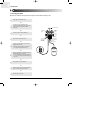
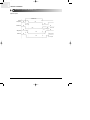
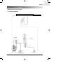
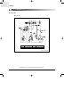
7-1. Refrigerating Cycle Block Diagram
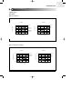
7-1-1. HEAT PUMP PREMIUM
PREMIUM 7,000 / 9,000BTU
MOLD OUTDOOR UNIT
Valve-4 Way
Air-in
Capi
Valve Packed 1/4"
Valve Packed 3/8"
SAMSUNG | 65
7
DB98_16444A(1)_2
7
2/9/04 10:05 AM
Page 66
DIAGRAM
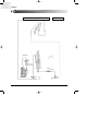
Refrigerating Cycle Block Diagram (cont.)
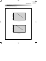
PREMIUM 12,000BTU
MOLD OUTDOOR UNIT
Valve-4 Way
Air-in
C-Capi
H-Capi
Check-Valve
Valve Packed 1/4"
Valve Packed 1/2"
66 | SAMSUNG
DB98_16444A(1)_2
2/9/04 10:05 AM
Page 67
DIAGRAM
Refrigerating Cycle Block Diagram (cont.)
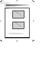
7-1-2. HEAT PUMP DELUXE
❏ 12K
DELUXE 7,000 / 9,000BTU
STEEL OUTDOOR UNIT
Valve-4 Way
Air-in
Capi
Valve Packed 1/4"
Valve Packed 3/8"
SAMSUNG | 67
7
DB98_16444A(1)_2
7
2/9/04 10:05 AM
Page 68
DIAGRAM
Refrigerating Cycle Block Diagram (cont.)
DELUXE 12,000BTU
STEEL OUTDOOR UNIT
Valve-4 Way
Air-in
Capi
Valve Packed 1/4"
Valve Packed 1/2"
68 | SAMSUNG
DB98_16444A(1)_2
2/9/04 10:05 AM
Page 69
DIAGRAM
Circuit Diagram
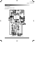
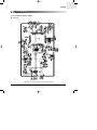
7-2. Circuit Diagram
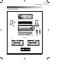
7-2-1. S✳07APG / S✳09APG / S✳12APG
● Indoor Unit (1)
This Document can not be used without Samsung's authorization.
SAMSUNG | 69
7
DB98_16444A(1)_2
7
2/9/04 10:05 AM
Page 70
DIAGRAM
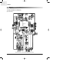
Circuit Diagram (cont.)
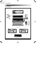
S✳07APG / S✳09APG / S✳12APG(cont.)
● Indoor Unit (2)
This Document can not be used without Samsung's authorization.
70 | SAMSUNG
DB98_16444A(1)_2
2/9/04 10:05 AM
Page 71
DIAGRAM
Circuit Diagram (cont.)
7-2-2. S✳07AS2 / S✳09AS2 / S✳12AS4
● Indoor Unit
This Document can not be used without Samsung's authorization.
SAMSUNG | 71
7
DB98_16444A(1)_2
7
2/9/04 10:05 AM
Page 72
DIAGRAM
Circuit Diagram (cont.)
● Outdoor Unit
■ 7K / 9K / 12K
C1
MOTOR CAPACITOR
C2
COMP CAPACITOR
FM
O.L.P
FAN MOTOR
OVER LOAD PROTECTOR
Code No : DB98-15123A
This Document can not be used without Samsung's authorization.
72 | SAMSUNG
DB98_16444A(1)_2
2/9/04 10:05 AM
Page 73
DIAGRAM
Circuit Description
7-3. Circuit Description
7-3-1. Indoor Fan Control
ZERO CROSSING PARTS
■
Use SSR(Solid State Relay) of Micom to change the ON Time until the 220V sine wave equals the fan motor rpm to control. In the
meantime, the Zero Crossing part will recognize AC220V as 0V to determine the Switching Timing.
As the Fan Control Port of Micom detects the "High" signal and the signal turns into "Low" past TR-Array(UL2003), the LED of SSR
obtains 12V, the same input wave with "2" and the Gate of Photo Triac obtains the operating voltage at the same time to determine
the time to turn on SSR. Now the indoor fan motor can operate at the desired rpm.
High RPM
Low RPM
Voltage
Voltage
Current
Current
SAMSUNG | 73
7
DB98_16444A(1)_2
7
2/9/04 10:05 AM
Page 74
DIAGRAM
Circuit Description (cont.)
7-3-2. Stepping Motor Control
S1
M
S4
S2
S3
■
As shown in the above figure, let the electric currents in sequence flow through the 4 windings to revolve the stepping motor. Of 3
methods of 4 couple stepping switch sequence, 1 Phase Exciter Method, 2 Phase Exciter Method, and 1-2 Phase Exciter Method,
the last method was adopted for this circuit. Based on this method, the signals come in the order of S1, S2, S3, and S4 to create
magnetic force and one frequency forms a cycle. When S1, S2, S3, and S4 receive the following signals respectively, the stepping
motor begins operation.
Power OFF (Closing) CCW ("1"=HIGH)
Power ON (Opening) CW ("0"=LOW)
Switch
1
2
3
4
5
6
7
8
1
2
3
4
5
6
7
8
1
1
0
0
0
0
0
0
S1
0
0
0
0
0
1
1
1
0
1
1
1
0
0
0
0
S2
0
0
0
1
1
1
0
0
0
0
0
1
1
1
0
0
S3
0
1
1
1
0
0
0
0
0
0
0
0
0
1
1
1
S4
1
1
0
0
0
0
0
0
Power OFF
Power ON
S1
S1
S2
S2
S3
S3
S4
S4
74 | SAMSUNG
DB98_16444A(1)_2
2/9/04 10:05 AM
Page 75
8
Troubleshooting
8-1. Troubleshooting for Non Inverter
8-2. Set up the Model Option
DB98_16444A(1)_2
2/9/04 10:05 AM
Page 76
DB98_16444A(1)_2
2/9/04 10:05 AM
Page 77
TROUBLESHOOTING
Troubleshooting for Non Inverter
8-1. Troubleshooting for Non Inverter
8-1-1. Items to be checked first
1.
The input voltage should be rating voltage ±10% range.
The airconditioner may not operate properly if the voltage is out of this range.
2.
Is the link cable linking the indoor unit and the outdoor unit linked properly?
The indoor unit and the outdoor unit shall be linked by 5 cables.
Check the terminals if the indoor unit and outdoor unit are properly linked by the same number of cables.
Otherwise the airconditioner may not operate properly.
3.
When a problem occurs due to the contents illustrated in the table below it is a symptom not related to the malfunction of the
airconditioner.
No
Operation of air conditioner
Explanation
1
The OPERATION indication LED(GREEN) blinks when a
power plug of the indoor unit is plugged in for the first time.
It indicates power is on. The LED stops blinking if the operation ON/OFF button on the remote control unit is pushed.
2
In a COOL operation mode, the compressor does not
operate at a room temperature higher than the setting
temperature that the INDOOR FAN should operate.
[In case of heat pump model]
In a HEAT operation mode, the compressor does not
operate at a room temperature lower than the setting
temperature that indoor fan should operate.
In happens after a delay of 3 minutes when the compressor
is reoperated. The same phenomenon occurs when a power
is on.
As a phenomenon that the compressor is reoperated after a
delay of 3 minutes, the indoor fan is adjusted automatically
with reference to a temperature of the air blew.
3
Fan speed setting is not allowed in DRY(
The speed of the indoor fan is set to LL in DRY mode.
Fan speed is selected automatically in AUTO mode.
4
Compressor stops operation intermittently in DRY(
mode.
5
Timer LED(GREEN) of the indoor unit lights up and the
air conditioner does not operate.
Timer is being activated and the unit is in ready mode.
The unit operates normally if the timer operation is cancelled.
6
The compressor stops intermittently in a COOL mode or
DRY mode, and fan speed of the indoor unit decreases.
The compressor stops intermittently or the fan speed of the
indoor unit decreases to prevent inside/outside air frozen
depending on the inside/outside air temperature.
7
[In case of heat pump model]
Compressor of the outdoor unit is operating although it is
turned off in a HEAT mode.
When the unit is turned off while de-ice is activated,
the compressor continues operation for up to 9 minutes
(maximum) until the deice is completed.
8
[In case of heat pump model]
The compressor and indoor fan stop intermittently in
HEAT mode.
The compressor and indoor fan stop intermittently if room
temperature exceeds a setting temperature in order to protect
the compressor from overheated air in a HEAT mode.
9
[In case of heat pump model]
Indoor fan and outdoor fan stop operation intermittently
in a HEAT mode.
The compressor operates in a reverse cycle to remove
exterior ice in a HEAT mode, and indoor fan and outdoor fan
do not operate intermittently for within 20% of the total heater
operation
) mode.
)
Compressor operation is controlled automatically in DRY
mode depending on the room temperature and humidity.
SAMSUNG | 77
8
DB98_16444A(1)_2
8
2/9/04 10:05 AM
Page 78
TROUBLESHOOTING
Troubleshooting for Non Inverter (cont.)
Items to be checked first(cont.)
4.
Indoor unit observes operation condition of the air conditioner, and displays self diagnosis details on the display panel.
LAMP
OPERATION
Error Mode
TIMER
TURBO
Indoor unit room temperature sensor error
(open or short)
Indoor unit heat exchanger temperature sensor error
(open or short)
Indoor fan motor malfunction
EEPROM error
Option error
(option wasn't set up or option data error)
: Lamp off
5.
: Lamp flickering
Operation with abnormal motion
No
1
2
Abnormal condition
No response from
the remote control
operation signal.
Unable to operate the
outdoor unit
78 | SAMSUNG
Inspection
• Plug out and plug in 5 seconds
later.
• Press the TURBO button with the
remote control.
• In 3 minutes, check the voltage
between the indoor unit terminal
block N(1) and 1.
Initial Diagnosis
Able to operate the
remote control.
OK
Unable to operate
the remote control.
Press the
(ON/OFF) button in the
indoor unit.
• If it operates, the remote control and
indoor unit receiver are in trouble.
• If not, the indoor unit is in trouble.
AC198V ~ AC242V
Problem with the outdoor unit or PCB
No power source
displayed.
Problem with the relay (RY71) or PCB
DB98_16444A(1)_2
2/9/04 10:05 AM
Page 79
TROUBLESHOOTING
Troubleshooting for Non Inverter (cont.)
8-1-2. Fault Diagnosis by Symptom
■ No Power (completely dead)-Initial diagnosis
1. Checklist :
1) Is input voltage normal?
2) Is AC power linked correctly?
3) Is input voltage of DC regulator IC KA7805 (IC02) normal? (11VDC-12.5VDC)
4) Is output voltage of DC regulator IC KA7805 (IC02) normal? (4.5VDC-5.5VDC)
2. Troubleshooting procedure
Unplug the power cord and
plug it after 5 seconds
Press the Power Button on the
remote control unit to
operate the air conditioner
operate
◆ Check the display board
does not operate
◆ Check the indoor unit
control board
Check whether two wires
of power cord are
connected correctly to the
terminal block and control board.
No
Reconnect wires correctly
Yes
Check whether the fuse on the
control board is normal.
FUSE: 3.15[A]/250[V]
No
Replace fuse
Yes
Check the output of SMPS
on the control board.
Input power: AC230±15%[V]
IC02 Input: DC 12[V]
IC02 output: DC 5[V]
No
PCB should be replaced
Yes
◆ Check the setting temperature
SAMSUNG | 79
8
DB98_16444A(1)_2
8
2/9/04 10:05 AM
Page 80
TROUBLESHOOTING
Troubleshooting for Non Inverter (cont.)
■ Room temperature sensor failure
LAMP
OPERATION
Description
TIMER
TURBO
7-segment
Display
: Lamp off
: Lamp flickering
Indoor unit room temperature sensor error(open or short)
Detach the assembly sensor from the
ASS'Y PCB CN43 connector and measure
the sensor resistance with an ohmmeter (tester).
Is the sensor resistance value
10KΩ ±3% at the room temperature
of 25˚C?
No
ASS'Y Sensor Replace
SENSOR Resistance Value : 20˚C-12.09kΩ
SENSOR Resistance Value : 30˚C-8.31kΩ
SENSOR Resistance Value : 35˚C-6.94kΩ
SENSOR Resistance Value : 40˚C-5.83kΩ
Yes
Connect the sensor to CN43,
supply power, and measure the voltage of
#1 and #2 of the CN43 connector.
Below 0.5V?
Yes
Poor ASS'Y PCB Replace
No
Yes
Over 4.9V?
No
MICOM Error or Connector(CN43) check
80 | SAMSUNG
Poor ASS'Y PCB Replace
DB98_16444A(1)_2
2/9/04 10:05 AM
Page 81
TROUBLESHOOTING
Troubleshooting for Non Inverter (cont.)
■ Room Pipe sensor failure
LAMP
OPERATION
Description
TIMER
TURBO
7-segment
Display
: Lamp off
: Lamp flickering
Indoor unit heat exchanger temperature sensor error
(open or short)
1. Check the assembly condition of the sensor connector(CN43) on the indoor unit Main PCB and if not assembled, reassemble the
connector accurately.
2. Detach the room pipe sensor connector(CN43) and check the resistance between connector 3 and 4.
Temperature(˚C)
Resistance Value(Kohm)
Temperature(˚C)
Resistance Value(Kohm)
15
14.68
30
8.31
20
12.09
35
6.94
25
10
40
5.83
Others
The data tolerance
is ±3%.
If the above data is not met, replace the room pipe sensor.
3. Assemble the room pipe sensor to PCB, plug in, and check the voltage of connector 3 and 4. If the resistance is below 0.5V or
over 4.9V, replace the indoor Main PCB. (short or disconnected in the PCB board)
SAMSUNG | 81
8
DB98_16444A(1)_2
8
2/9/04 10:05 AM
Page 82
TROUBLESHOOTING
Troubleshooting for Non Inverter (cont.)
■ When the Indoor Unit Fan Does Not Operate. (Initial Diagnosis)
LAMP
OPERATION
Description
TIMER
TURBO
7-segment
Display
: Lamp off
: Lamp flickering
Indoor fan motor malfunction
1. Checklist :
1) Is the indoor unit fan motor properly connected with the connector (CN72)?
2) Is the AC voltage correct?
3) Is HALL IC in indoor fan motor properly connected with the connector (CN44)?
4) Is the running capacitor (CR71) properly connected with PCB board?
2. Troubleshooting procedure
After unplugging out the power cord should
be reconnected within 5 seconds.
Yes
No
Check as in the procedure "NO power"
Does the OPERATION lamp blink?
Yes
No
Does the Solid State Relay(SS71) work properly?
Test rod location
+
-
SS71-
SS71-
Micom is
out of order.
Micom should be replaced
Normal
Voltage
12V
Yes
No
Is the supply voltage of the fan motor sufficient?
Test rod location
PCB CN72
Condition
pin #3 and #5
Fan operating
PCB is
out of order.
PCB should be replaced.
Normal
voltage
About AC 180V
Motor Fan-Capacitor is out of order
Yes
Fan motor is out of order.
82 | SAMSUNG
Replace Motor
Fan-Capacitor
Fan motor should be replaced.
DB98_16444A(1)_2
2/9/04 10:05 AM
Page 83
TROUBLESHOOTING
Troubleshooting for Non Inverter (cont.)
■ When the Outdoor Unit Does Not Operate. (Initial Diagnosis)
1. Checklist :
1) Is input voltage normal?
2) Is the set temperature of the remote control higher than room temperature in COOL mode?
3) Is the set temperature of the remote control lower than room temperature in HEAT mode?
4) Is the POWER IN connector (CN71) linked correctly?
5) Is the outdoor unit properly connected with the TERMINAL BLOCK connector(N(1), 1, 2, 3)?
2. Troubleshooting procedure
After unplugging out the power cord should be
reconnected within 5 seconds.
No
Does the OPERATION lamp blink
Check as in the procedure "No Power"
Yes
Yes
Does the timer lamp blink during operation ?
Room temperature sensor is
out of order
!
No
#
+
-
Condition
Normal
Voltage
IC4 Pin No.38
GND
RY71 ON
DC 4.8V
Micom is
out of order.
No
Is the power relay RY71 operated by adjusting the
room temperature?
Test rod location
Sensor Should be
replaced
@
PCB should be
checked.
No
Power relay is
out of order
Is rating voltage ±10% range applied relay between
Terminal block No. N(1) and No. 1
Yes
Power relay should be
replaced.
Outdoor unit is
out of order.
!
Yes
No
@
Is the room sensor normal resistor?
10°C
20°C
30°C
17.96kΩ
12.09kΩ
8.3kΩ
Yes
#
SAMSUNG | 83
8
DB98_16444A(1)_2
8
2/9/04 10:05 AM
Page 84
TROUBLESHOOTING
Troubleshooting for Non Inverter (cont.)
■ When the UP/DOWN Louver Motor Does Not Operate. (Initial Diagnosis)
1. Checklist :
1) Is input voltage normal?
2) Is the UP/DOWN louver motor properly connected with the connector (CN61)?
2. Troubleshooting procedure
Remove power cord and plug in again in approx. 5 seconds.
No
Is STD lamp blinking?
Check as in the procedure
"No Power".
Yes
Yes
Does operation start when swing button of the
remote control unit pushed?
Normal
No
Voltage at pin #57~#60 of micom (IC04) change?(Squarewave)
No
Micom (IC04) is faulty.
Yes
No
Voltage at pin #2 ~ #5 of CN61(motor connector)
change?(Squarewave)
Driver IC06/08 (ULN2003A) is faulty.
Yes
UP/DOWN louver motor is faulty.
■ In the HEAT mode, When there is no warm air current. Check this fist;
(1) Is the set temperature of Remote Control lower than room temperature in Heat mode?
(2) Is the Indoor PCB properly connected with the CN71 connector?
After training on, the heating operation
should start in 5 minutes.
Yes
Normal
No
Is the number #38 of Micom (IC04) DC 5.0V?
No
Abnormal Micom
Yes
Is the number checking #11 of IC05 (ULN2003A) LOW?
No
Abnormal IC05
Yes
Is the voltage between CN71 #1 and CN71 #5 rating voltage ±10% range
No
Abnormal RY73
Yes
Abnormal 4-Way valve of Outdoor Unit.
or connecting Cable
4-Way valve should be replaced
or connecting Cable Check.
84 | SAMSUNG
PCB should be replaced.
DB98_16444A(1)_2
2/9/04 10:05 AM
Page 85
TROUBLESHOOTING
Troubleshooting for Non Inverter (cont.)
■ When the remote control is not receiving
1. Check if the connector was normally assembled.
2. Put the set in operation and check the voltage of No. 3(+) and No. 2(-) of the main PCB CN91 while operating the
remote control. When the voltage descends below 3V, the assembly module PCB is normal and the main PCB is poor.
Then replace the main PCB.
3. Replace the assembly display PCB because the module PCB is poor if the voltage between No. 2~3 of CN91
maintains 5V after the remote control starts operation.
SAMSUNG | 85
8
DB98_16444A(1)_2
8
2/9/04 10:06 AM
Page 86
TROUBLESHOOTING
Set up the model Option
8-2. Set up the Model Option
8-2-1. S✳07APG / S✳09APG / S✳12APG
ex) Option No. :
Step 1 : Enter the Option Setup mode.
1st
Take out the batteries of remote control.
2nd
Press the temperature
insert the battery again.
3rd
Make sure the remocon display shown as
button simultaneously and
.
Step 2 : Enter the Option Setup mode and select your option according to the following procedure.
1
The default value is
Otherwise, push the
.
button to
.
Every time you push the button, the display panel reads
or
repeatedly.
2
Push the
3
3
Push the
4
5
.
Every time you push the button, the display panel reads
...
repeatedly.
2
1
button to set the display panel to
button to set the display panel to
.
Every time you push the button, the display panel reads
...
repeatedly.
6
4
Push the
button to set the display panel to
.
Every time you push the button, the display panel reads
...
repeatedly.
5
Push the
button to set the display panel to
.
Every time you push the button, the display panel reads
...
repeatedly.
6
✳ Setting is not required if you must
a value which has a
default.
86 | SAMSUNG
Push the
button to set the display panel to
.
Every time you push the button, the display panel reads
...
repeatedly.
DB98_16444A(1)_2
2/9/04 10:06 AM
Page 87
TROUBLESHOOTING
Set up the Model Option (cont.)
7
Press
button, then the default value is
.
8
Push the
button to set the display panel to
.
Every time you push the button, the display panel reads
...
repeatedly.
9
8
9
Push the
button to set the display panel to
.
Every time you push the button, the display panel reads
...
repeatedly.
7
10
10
11
Push the
12
button to set the display panel to
.
Every time you push the button, the display panel reads
...
repeatedly.
11
Push the
button to set the display panel to
.
Every time you push the button, the display panel reads
...
repeatedly.
12
Push the
button to set the display panel to
.
Every time you push the button, the display panel reads
...
repeatedly.
✳ Setting is not required if you must
a value which has a
default.
Step 3 : Upon completion of the selection, check you made right selections.
Press the Mode Selection key,
to set the display part to and check the display part.
The display part shows
Press the Mode Selection key,
The display part shows
.
to set the display part to
and check the display part.
.
Step 4 : Pressing the ON/OFF button (
)
When pressing the operation ON/OFF key with the direction of remote controller for unit, the sound ''Ding'' or ''Diriring'' is
heard and the OPERATION ICON(
) lamp of the display is flickering at the same time, then the input of option is completed. (If the diriring sound isn't heard, try again pressing the ON/OFF button.)
Step 5 : Unit operation test-run
First, Remove the battery from the remote controller.
Second, Re-insert the battery into the remote controller.
Third, Press ON/OFF key with the direction of remote controller for set.
• Error Mode
1st If all lamps of indoor unit are flickering, Plug out, plug in again and press ON/OFF key to retry.
2nd If the unit is not working properly or all lamps are continuously flickering after setting the option code, see if the correct option code is
set up for its model.
SAMSUNG | 87
8
DB98_16444A(1)_2
8
2/9/04 10:06 AM
Page 88
TROUBLESHOOTING
Set up the Model Option (cont.)
8-2-2. S✳07AS2 / S✳09AS2 / S✳12AS4
ex) Option No. :
Step 1 : Enter the Option Setup mode.
1st
Take out the batteries of remote control.
2nd
Press the temperature
insert the battery again.
3rd
Make sure the remocon display shown as
button simultaneously and
.
Step 2 : Enter the Option Setup mode and select your option according to the following procedure.
1
The default value is
Otherwise, push the
.
button to
.
Every time you push the button, the display panel reads
or
repeatedly.
1
2
2
button to set the display panel to
.
Every time you push the button, the display panel reads
...
repeatedly.
3
4
Push the
3
Push the
button to set the display panel to
.
Every time you push the button, the display panel reads
...
repeatedly.
5
6
4
Push the
button to set the display panel to
.
Every time you push the button, the display panel reads
...
repeatedly.
5
Push the
button to set the display panel to
.
Every time you push the button, the display panel reads
...
repeatedly.
✳ Setting is not required if you must
a value which has a
default.
88 | SAMSUNG
6
Push the
button to set the display panel to
.
Every time you push the button, the display panel reads
...
repeatedly.
DB98_16444A(1)_2
2/9/04 10:06 AM
Page 89
TROUBLESHOOTING
Set up the Model Option (cont.)
7
Press
button, then the default value is
.
8
Push the
7
button to set the display panel to
.
Every time you push the button, the display panel reads
...
repeatedly.
8
9
9
Push the
button to set the display panel to
.
Every time you push the button, the display panel reads
...
repeatedly.
10
11
10
Push the
12
button to set the display panel to
.
Every time you push the button, the display panel reads
...
repeatedly.
11
Push the
button to set the display panel to
.
Every time you push the button, the display panel reads
...
repeatedly.
12
✳ Setting is not required if you must
a value which has a
default.
Push the
button to set the display panel to
.
Every time you push the button, the display panel reads
...
repeatedly.
Step 3 : Upon completion of the selection, check you made right selections.
Press the Mode Selection key,
to set the display part to and check the display part.
The display part shows
.
Press the Mode Selection key,
The display part shows
to set the display part to
and check the display part.
.
Step 4 : Pressing the ON/OFF button (
)
When pressing the operation ON/OFF key with the direction of remote controller for unit, the sound ''Ding'' or ''Diriring'' is
heard and the OPERATION ICON( ) lamp of the display is flickering at the same time, then the input of option is completed. (If the diriring sound isn't heard, try again pressing the ON/OFF button.)
Step 5 : Unit operation test-run
First, Remove the battery from the remote controller.
Second, Re-insert the battery into the remote controller.
Third, Press ON/OFF key with the direction of remote controller for set.
• Error Mode
1st If all lamps of indoor unit are flickering, Plug out, plug in again and press ON/OFF key to retry.
2nd If the unit is not working properly or all lamps are continuously flickering after setting the option code, see if the correct option code is
set up for its model.
SAMSUNG | 89
8
DB98_16444A(1)_2
8
2/9/04 10:06 AM
Page 90
TROUBLESHOOTING
Set up the Model Option (cont.)
■ OPTION ITEMS
REMOCON
SEG1
SEG2
SEG3
SEG4
SEG5
SEG6
SEG7
SEG8
SEG9
SEG10
SEG11
SEG12
SH07APG
0
2
6
0
6
4
1
7
0
2
2
E
SH09APG
0
2
6
5
6
5
1
7
0
3
5
1
SH12APG
0
6
7
0
6
4
1
7
0
3
6
2
SH07AS2
0
2
6
0
6
5
1
7
A
0
F
b
SH09AS2
0
2
6
0
6
5
1
7
A
2
2
E
SH12AS4
0
6
8
0
2
4
1
7
A
3
5
1
MODEL
90 | SAMSUNG
DB98_16444A(1)_2
2/9/04 10:06 AM
Page 91
MEMO
SAMSUNG | 91
DB98_16444A(1)_2
2/9/04 10:06 AM
Page 92
MEMO
92 | SAMSUNG
DB98_16444A(1)_CO
2/9/04 10:02 AM
Page 1
2004. 2
ELECTRONICS
© Samsung Electronics Co.,Ltd.Feb. 2004.
Printed in Korea.
Code No. DB98-16444A(1)
2
0
0
4
.
2
AIR CON