1
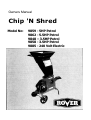
Owners Manual
Chip 'N Shred
Model No:
9859 - 5HP Petrol
9862 - 5.5HP Petrol
9848 – 3.5HP Petrol
9858 - 3.5HP Petrol
9885 - 240 Volt Electric
Rover Mowers Limited
Chip `N Shred
PREFACE
Congratulations on your purchase of a quality Australian made and owned ROVER product.
This manual covers the operation of the petrol and electric powered Rover Chip `N Shred.
Please read and understand this Owners Manual, and the accompanying Engine manufacturers manual for
petrol models.
If any point is unclear, contact Rover Mowers Limited or any authorised Rover Mower service dealer.
WARNING
The safety of the user and others
involved. Personal injury may result
should this information be disregarded
CAUTION
Follow these instructions to avoid
machine damage and possible loss of
warranty.
CONTENTS
Preface . ............................................................. iii
Safety instructions . ............................................ iv
1.
Specifications ...............................................1
2.
2.1
2.2
2.3
2.4
2.5
2.6
2.7
Setting up .....................................................1
Loose parts kit ...............................................1
Hopper, handle and baffle assembly . ............2
Hopper assembly to body .:. ..........................2
Chipper tube to body . ...................................2
Mulch bag . ....................................................2
Engine lubrication - Petrol Models ................2
Fuel - Petrol Models . ....................................3
3.
3.1
3.2
3.3
3.4
3.5
3.6
3.7
3.8
3.9
3.10
4.
4.1
4.2
4.3
4.4
4.5
4.6
4.7
4.8
4.9
4.10
Operation .....................................................3
To start the engine - Petrol Models . ..............3
To stop the engine - Petrol Models ...............3
Rotor engagement - Petrol Models . ..............3
Rotor disengagement - Petrol Models . ..........3
Operation - Electric Models . ..........................3
Shredding Material .......................................3
Chipper tube feeding . ...................................3
Screens . ........................................................4
Screen removal . ............................................4
Screen fitting ..................................................4
Maintenance
Oil Change - Petrol Models.............................4
Lubrication points - Petrol Models...................4
Drive belt adjustment - Petrol Models .............4
Drive belt adjustment - Electric Models . ........4
Chipper blade removal and fitting . .................5
Chipper blade sharpening .............................5
Flails .............................................................5
Flail removal . ................................................5
Flail fitting . ....................................................5
Routine maintenance......................................5
5.
5.1
5.2
5.3
5.4
5.5
5.6
5.7
Composting . ..................................................... 6
Mulch ................................................................ 6
Compost ........................................................... 6
Humus . .............................................................. 6
Mulching the garden . ........................................ 6
Composting ...................................................... 6
Suitable materials for composting . .................... 6
Materials that should never be composted . ....... 6
ILLUSTRATIONS
Figure 1.
Figure 2.
Figure 3.
Figure 4.
Figure 5.
Figure 6.
Figure 7.
Figure 8.
Figure 9.
Figure 10.
Figure 11.
Figure 12.
Hopper assembly . ......................................... i
Hopper baffle fitting . ...................................... i
Hopper handle to hopper . ............................. i
Hopper assembly to body ............................. i
Chipper tube to body assembly ..................... i
Mulch bag fitting ........................................... i
Clutch lever - Petrol Models . ........................ ii
Screen fitting , ............................................... ii
Drive belt adjustment - Petrol Models............. ii
Drive belt adjustment - Electric Models .......... ii
Chipper blade removal and fitting................... ii
Rotor assembly.............................................. ii
Rover Mowers Limited
Chip `N Shred
Training
•
•
•
•
•
•
Become familiar with the Owner's Manual before
attempting to operate this equipment.
Do not allow children to operate this equipment.
Do not operate this equipment in the vicinity of
bystanders.
Carbon dioxide can be extremely dangerous in
enclosed areas; do not run the machine in an
enclosed area since the exhaust from the engine
contains carbon monoxide, which is colourless,
odourless, and tasteless.
Do not place hands or any other part of the body or
allow clothing inside the feeding chamber, discharge
chute, or near any moving part.
Before inspecting or servicing any part or the
machine, shut off the power supply, disconnect the
power cord or disconnect the spark plug lead from
the spark plug, and make sure that all moving parts
have come to a complete stop.
•
competent to do so.
•
•
•
•
•
•
•
•
•
If the cutting mechanism strikes any foreign objects
or if the machine should make any unusual noise
or vibration, immediately switch off the engine and
allow the machine to stop. Disconnect the spark
plug wire from the spark plug or remove power
cord from power supply and take the following
steps.
a. Inspect for damage
b. Replace or repair any damaged parts.
c. Check for and tighten any loose parts.
Do not attempt to repair the machine unless you are
Preparation
Obtain and wear safety glasses and gloves at all
times while operating the machine.
Avoid wearing loose fitting clothing. Operate the
machine only on a level surface.
Do not operate the machine on a paved or gravel
surface. Thrown objects could cause injury.
Before starting the machine, check that all screws,
nuts, bolts, and other fasteners are properly
secured. Replace damaged or unreadable warning
and operator labels.
Use extra care in handling petrol and other fuels.
They are flammable and vapours are explosive.
a. Use only an approved container.
b. Never remove fuel cap or add fuel with the
engine running. Allow engine to cool before
refuelling. Do not smoke.
c. Never refuel the machine indoors.
d. Never store the machine or fuel container inside
where there is an open flame, such as a gas
water heater.
SAFETY INSTRUCTIONS
•
•
•
•
•
•
Keep the engine clean of debris and other
accumulations to prevent damage to the engine or
possible fire.
Do not allow processed material to build up in the
discharge area. This may prevent proper discharge
and can result in kickback of material through the
feed opening.
Keep all guards and deflectors in place and in good
working condition.
Always stand clear of the discharge area when
operating this machine.
Keep your face and body away from the feed
opening.
Do not overreach. Keep proper balance and footing
at all times.
Do not tamper with the engine governor settings on
petrol engines; the governor controls the maximum
safe operating speed and protects the engine and all
moving parts from damage caused by over speed.
Seek authorised service if a problem exists.
Do not transport this machine while the engine is
running.
If the machine becomes clogged, switch-off the
engine and disconnect the spark plug lead or
remove the power lead from power supply, before
cleaning debris away.
Switch-off the unit before attaching or removing the
mulch bag.
Maintenance
Operation
•
•
Before starting the machine, make certain that the
cutting chamber is empty.
When feeding shreddable material into the
equipment be extremely careful that pieces of metal,
rocks, bottles, cans or other foreign objects are not
included.
•
•
When this equipment is stopped for servicing, inspection, or storage, or to change an accessory,
make sure the spark plug lead is disconnected from
the spark plug, or the power cord is removed from
power supply. Allow the machine to cool before
making any inspections, adjustments, etc. Maintain
the machine with care and keep it clean.
Store the machine out of the reach of children and
where petrol vapours will not reach an open flame or
spark. For extended storage periods, run the unit dry
of fuel. Always allow the machine to cool before
storing.
Rover Mowers Limited
Chip `N Shred
General Electrical Safety Rules
1.
2.
3.
4.
5.
6.
Avoid dangerous environments such as damp
locations.
Do not abuse the power cord. Never pull a machine
by the cord or pull the cord to disconnect it from the
outlet socket. Keep the cord away from excessive
heat, oil, and sharp edges.
Disconnect the machine when not in use, before
servicing and when changing attachments.
Avoid accidental starting. Be sure to switch off
before plugging the cord into a power outlet.
To prevent electrical shock, use the machine only
with an extension cord suitable for outdoor use as
recommended by the extension cord manufacturer;
the use of suitable extension cords is extremely
important for the operator's personal safety.
Never use an indoor type of extension cord: these
cords are designed for use with lamps and small
appliances and are inadequate for high-powered
machines.
SAFETY INSTRUCTIONS
7. Make sure the extension cord is in good condition. A
cord with cracked or broken insulation is hazardous,
particularly in the presence of moisture or
combustible material. It is also important that the
cord connectors be of rugged construction, in good
condition, and securely attached to the outer jacket.
8. If the extension cord is damaged in any manner while
operating the machine, immediately switch off the
power supply and remove the extension cord from the
power outlet.
9. If the supply cord is damaged it must be replaced by
a CMG Service Agent or similarly qualified person in
order to avoid a hazard.
Electrical Supply Capacity and Fuses
1.
2.
Use only an electric circuit having adequate
capacity.
Blowing a fuse or tripping a circuit breaker is a
warning that you are overloading your machine or
have too many devices in use on that circuit, or
both. Determine the cause and correct it. Do not
install a higher capacity fuse.
1. SPECIFICATIONS
Rover Model No:
Engine Model No:
Power rating
Fuel Capacity
Oil Capacity
Oil Grade
Spark Plug
Spark Plug Gap
Voltage
Current FL.
Frequency
Phase
No. Flails
No. chipper blades
Chipper opening
Weight
9885 (Electric)
9858 (Petrol)
9859 (Petrol)
A09189
2.42 Kw (High Torque)
91202
2.6 Kw
1.9 litres
600ml
SAE 30
RJ 19 LM
0.7 - 0.8mm
135202
3.75 Kw
2.85 litres
600ml
SAE 30
RJ 19 LM
0.7 - 0.8mm
12
1
71 x 71 mm
12
1
240 volts
10 amps
50Hz
Single
12
1
71 x 71 mm
56
2.1 Loose Parts Kit
Feed hopper half LH. ............................................ 1
Feed hopper half RH. ............................................. 1
Hopper baffle ........................................................ 1
Hopper handle ....................................................... 1
Hopper washers ..................................................... 4
Chipper tube assembly ........................................... 1
Manual .................................................................. 1
Bar screen assembly ............................................. 1
Screws- 10 x 3/4" pan p/head .............................. 12
Bolts- 1/4" x 1-1/2" unc. cuphead .......................... 4
Nyloc nuts- 1/4" unc. ............................................. 4
Screws- 3/16" x 5/8" mush.head.............................. 4
51
71 x 71 mm _
56
2. SETTING UP
Nyloc nuts- 3/16" unc. ........................................... 4
Washer- 3/16" x 1/2" x 20g.flat ............................. 4
Washer- 3/16" x 3/4" x 16g.flat ............................. 4
Nyloc nuts- 5/16" unc. ........................................... 7
Setscrew- 5/16" x 1" unc. hex. ............................... 7
Washers- 5/16" x 5/8" x 18g. flat ........................... 7
When disassembling the timber packing, discard the four
nuts and retain the bolts and washers for the handle
assembly. The four nyloc nuts found in the loose parts
list are to be used on the handle bolts.
Rover Mowers Limited
Chip `N Shred
2.2 Hopper handle and baffle assembly
The feed hopper as supplied with the Chip `N
Shred needs to be assembled before use.
1. Lay the right hand side half of the hopper down on
a flat surface with the joint flange pointing up.
2. Position the left hand side half of the hopper on top
of the right hand side aligning the joint flange and
screw holes. Figure 1.
3. Insert the self tapping screws in the front
flanged joint in the sequence shown (1-6) and
tighten. Figure 1.
4. Insert the self tapping screws in the rear flanged
joint in the same sequence as in the front flange
and tighten. Figure 1.
5. Support the hopper in an upright position and fit the
hopper baffle inside the hopper by aligning the four
holes in the top edge of the baffle with the four
matching holes on the ledge in the top of the
hopper. Figure 2.
6. Retain the hopper baffle with the four 3/16" x 5/8"
mush.head screws with the four large 3/16" Flat
washers under their heads and inserted from the
inside with the 3/16" small flat washers and 3/16"
nyloc nuts on the outside of the hopper. Figure 2.
7. Locate the hopper handle and slide it into the
grooves located near the top of the hopper body so
that the holes in the handle are in alignment with
the holes in the hopper. Figure 3.
8. Retain the hopper handle with the four 1/4" x 1-1/2"
unc. cuphead bolts inserted from the inside of the
hopper with the four 1/4" unc. nyloc nuts on the
outside. Figure 3.
2.3 Hopper assembly to body
WARNING
The hopper assembly must be fitted to the
Chip `N Shred body before attempting to
start or use the Chip `N Shred.
1.
2.
3.
Lift the hopper into position on top of the flange on
the Chip `N Shred body with the hopper handle
pointing out over the engine.
Align the slots in the hopper flange with the holes
in the body flanges, and insert four 5/16" x 1 " unc
bolts with the hopper washers under their heads.
Figure 4.
Retain with four 5/16" washers and four 5/16" nyloc
nuts under the body flange and tighten. Figure 4.
SETTING UP
2.4 Chipper tube to body
WARNING
The chipper tube assembly must be fitted to
the Chip `N Shred body before attempting to
start or use the Chip `N Shred.
1.
2.
3.
4.
Remove the rotor shaft cover from the bearing.
Slide the chipper tube assembly into the
rectangular port on the right hand side of the Chip
`N Shred so that the holes in the flanges on the
chipper tube align with the studs on the Chip `N
Shred body. Figure 5.
Retain the chipper tube assembly with three 5/16"
unc. nyloc nuts and three 5/16" flat washers.
Replace the rotor shaft cover.
2.5 Mulch bag
Assembly
1. Slide the Mulch bag frame into the pockets along the
top edge of each side of the mulch bag.
2. Slide the spreader tube onto the ends of the bag
frame till the hole in the frame are within the tube
and retain with the two `R' clips inserted into the
holes in the frame.
Fitting
3. Slide the mulch bag under the Chip `N Shred from
the front between the support legs and rest the
mulch bag frame on the rear wheel supports. Lift the
front bar of the mulch bag frame over the front lip on
the front legs support. Figure 6.
2.6 Engine lubrication - Petrol Models
The engine oil level must be checked before attempting
to start the engine.
Refer
to the engine
manufacturer's instructions.
1.
2.
3.
4.
Position the Chip `N Shred on a level surface.
Clean around the dip stick.
Remove the dip stick from the oil filler tube.
Using a funnel slowly add oil in accordance with the
engine manufacturer's instructions.
Check the oil level by screwing in the dip stick and
removing again. When the oil level is correct
replace the dip stick securely.
CAUTION
Avoid premature engine failure by using a
clean funnel and cleaning away any possible
contaminants.
Rover Mowers Limited
Chip `N Shred
SETTING UP
2.7 Fuel
3.
1.
2.
Position the Chip `N Shred on a level surface in a well
ventilated area. Clean around the fuel tank cap.
Remove the fuel tank cap.
4.
5.
Using a clean funnel fill the fuel tank with clean fresh
unleaded petrol.
Replace the fuel tank cap. 5.
Wipe up any spilt petrol.
3. OPERATION
3.1 To start the engine - Petrol Models
Refer to the engine manufacturers instructions.
3.
1.
Move the clutch lever to the disengaged position.
4.
2.
Move the choke lever to the choke position.
3.
4.
5.
Move the throttle lever to the fast
position.
Move the fuel shutoff valve to the on position (if fitted).
Move the Stop Control switch to the on position (if
fitted).
Grasp the starter cord and pull.
6.
7.
When the engine starts, move the choke lever to the
run position and the throttle lever to the slow
position.
3.2 To stop the engine - Petrol Models
Refer to the engine manufacturers instructions
WARNING
Blades continue to free wheel after engine has
been switched off
5.
To stop the Chip `N' Shred move the motor switch to the
'Off' position `O'.
If the overload switch activates during operation wait 60
seconds, reset the overload and switch the unit back on.
This will allow the electric motor time to cool and the
overload switch to reset.
If after waiting 60 seconds the Chip `N Shred fails to
restart the following procedure should be followed.
a. Switch the machine off and disconnect the power
supply.
b. Check for blockages and that the rotor is free to
rotate. If the rotor is jammed remove the screens to
clear blockage. Refer to section 3.9.
c. Connect to the power supply and switch on the Chip
`N Shred.
d. If the Chip `N Shred will not start check the fuse or
circuit breaker on the electrical circuit being used
and rectify if necessary.
e. If the Chip `N Shred will not start and the electrical
circuit is found to be operational, contact your local
authorised Rover service dealer.
3.6 Shredding material
1.
2.
3.
4.
Move the throttle lever to the off position. O
Move the fuel shutoff valve to the off position (if fitted).
Move the stop control switch to the off position (if fitted).
Move the clutch lever to the disengaged position if
engaged.
3.3 Rotor engagement - Petrol Models
1.
Start the engine as per the section 3.1.
2.
3.
Move the throttle control to the fast position.
Slowly move the clutch lever on the left hand side of the
Chip `N Shred to the engaged position. Figure 7.
3.4 Rotor disengagement - Petrol Models
1.
2.
Move the rotor clutch lever to the disengaged position.
`O' Figure 7.
Move the throttle control to the slow
or off `O'
position as required.
3.5 Operation - Electric Models
1.
2.
Connect the Chip `N Shred to a suitable power supply
with a 15amp rated power cord fitted with 10 amp fittings
no longer than 20 meters long. Longer cords will result
in voltage drop and possible premature overload drop
out and or possible motor damage.
To start the Chip `N Shred move the motor switch to the
`On' position `I'.
1.
Start the Chip `N Shred engine as per section 3. L
for petol models or section 3.5 for electric models.
WARNING
Operators should always wear safety glasses,
hearing protection and gloves while operating the
Chip `N Shred.
2.
3.
4.
5.
Engage the rotor clutch as per section 3.3. Petrol
Models only.
Feed branches with foliage first into hopper so as to
control the rate of feed. Maximum branch size in
shredder hopper is approximately 20mm diameter.
When feeding vines or long stringy types of material
into the Chip `N Shred, cut them first into lengths of
no more than 600mm long. Be careful not to wrap
materials around hands when feeding.
Do not feed at a faster mate than the Chip `N Shred
can shred and discharge material, as you may stall
the rotor and overload the engine and or damage
the drive belt.
3.7 Chipper tube feeding
Feed larger branches, up to approximately 70mm diameter,
into the chipper tube. Control the rate of feed by pulling back
on the branch so as not to block the unit and cause it to stall.
Rover Mowers Limited
Chip `N Shred
OPERATION
3.8 Screens
3.10 Screen fitting
Two screens are supplied with the Chip `N Shred, the
standard screen consisting of numerous holes in acurved
plate and a bar screen consisting of widely spaced bars
between two side plates.
The size of the mulch produced by either shredding or
chipping is dependent on the screen fitted to the Chip `N
Shred
The screen to be used depends on the type of material to be
processed. The standard screen suits most types of material
found in the garden. If moist, pulpy or soggy types of material
are to be processed the bar screen should be fitted to avoid
blockages.
1.
2.
3.
Switch the engine off and remove the spark plug lead
from the spark plug or disconnect the power cord from the
power supply.
Choose the correct screen for the material to be
processed (refer to section 3.8).
Lift and position the screen in the Chip `N Shred by
aligning the holes in the screen and the Chip `N Shred
body. Insert the screen rod closest to the engine first and
secure with the R-clip retainer. Figure 8.
Note: The standard screen can be fitted in the Chip `N
Shred in either direction. The Bar Screen will only fit with
the bars pointing away from the engine.
3.9 Screen removal
4.
1.
2.
3.
Switch engine off.
Remove the spark plug lead from the spark plug or
disconnect the power cord from the power supply.
When the rotor has come to a stop remove the R-clips
from the screen bars and remove the screen bars, the
screen should then drop out through the discharge chute.
Figure 8.
Lift the front of the screen and insert the screen rod
through the Chip `N Shred side plate, retaining with the Rclip.
CAUTION
Do not tip petrol models over when full of Petrol and Oil.
4. MAINTENANCE
4.1 Oil change Petrol Models
5.
Refer to the manufacturer's instructions.
1. Position the Chip `N Shred on a level surface in a well
ventilated area.
2. Start and run the engine for 5 minutes to warm up the
engine oil.
3. Place a container under the oil drain plug.
4. Using a 7/16" AF open end spanner remove the engine
drain plug and tilt the Chip `N Shred to allow the engine
oil to drain completely.
5. Refit the engine drain plug tightly and clean up any spilt
oil.
6. Fill the engine crankcase with oil. Refer to section 2.6
Engine Lubrication.
6.
7.
8.
CAUTION
Do not over tighten drive belt.
4.4 Drive Belt adjustment - Electric Models
4.2 Lubrication Points Petrol Models
1.
Using 10w -30 or S.A.E. 30 oil
1. Clutch lever point.
2. Throttle control.
2.
3.
4.
4.3 Drive belt adjustment - Petrol Models
1.
2.
3.
4.
Stop the Chip `N Shred and remove the spark plug lead
from the spark plug.
Remove the drive belt guard.
Move the clutch lever to the engaged position.
Loosen the four engine mount bolts.
Slide the engine away from the Chip `N Shred body to
tighten the drive belt. The drive belt should deflect about
6mm when hand pressure is applied, between the engine
pulley and the rotor shaft pulley. Figure 9.
Tighten the engine mount bolts.
Replace the drive belt guard aligning the `E' hole with
retaining stud.
Move the clutch engagement lever to the disengaged
position and replace the spark plug lead.
5.
6.
Stop the Chip `N Shred and disconnect from the power
supply.
Remove the drive belt guard
Loosen the four engine mount bolts `A' figure 10.
Tension the drive belt to give a 6mm deflection when
hand pressure is applied, by holding the nut `B' with a
9/16" A/F spanner and rotating the bolt `C' clockwise.
Tighten the four engine mount bolts.
Replace the drive belt guard aligning the `E' hole with
retaining stud.
WARNING
The chipper blade is extremely sharp and caution
must be used when handling or working with it.
Rover Mowers Limited
Chip `N Shred
MAINTENANCE
4.5 Chipper blade removal and fitting
4.8 Flail removal
Chipper blade removal
1.
2.
3.
Remove the hopper assembly.
Remove the belt guard.
Remove the chipper tube assembly.
4.
Rotate the rotor assembly until the flail bar to be
removed is opposite the pilot hole in the left hand side
of the Chip `N' Shred TM body.
Remove the flail bar retaining nut and bolt from the
shaft.
Using a drift inserted through the pilot hole in the
chipper shredder side plate, drive out the flail bar
through the chipper tube port.
1.
2.
3.
4.
5.
Stop the Chip `N' ShredTM and remove the spark plug
lead from the spark plug, or remove the power cord
from the power supply.
Remove the three retaining nyloc nuts and washers
from the chipper tube and lift off.
Remove the hopper assembly fasteners and lift the
hopper assembly off the Chip `N' ShredTM body.
Rotate the rotor to expose the chipper blade in the
chipper tube port.
Using a 1 /2" AF ring spanner and a Allen key remove
the chipper blade fasteners and remove the chipper
blade. Figure 11.
Chipper blade fitting
1.
2.
3.
4.
5.
Clean the surface ofthe rotor plate where the chipper
blade is attached.
Using new 5/16" Nyloc nuts fit the chipper blade to the
rotor plate and tighten the nyloc nuts to 19 Nm.
Fit the hopper assembly to the Chip 'N' Shred" body.
Refer to section 2.3.
Fit the chipper tube to Chip `N' Shred" body. Refer
section 2.4.
Move the clutch engagement lever to the disengaged
position and replace the spark plug lead.
4.6 Chipper blade sharpening
To maintain optimum performance from the chipper the
blade should be kept sharp. The chipper blade can be
ground back a total of 3mm before replacement of the
chipper blade is necessary.
TM
1. Remove the chipper blade from the Chip `N' Shred
Refer to section 4.5.
2. Maintain the same angle on the blade cutting edge
when grinding.
3. Remove any feathers that form by lightly honing the
chipper blade on an oil stone.
4. Refit to the Chip `N' Shred TM . Refer to section 4.5.
5.
6.
4.9 Flail fitting
1
2
3
4
5
6
7
8
Determine which flail bar is to be fitted from (Figure
12), and layout next to the Chip `N' ShredTM the flail
blades and spacers.
Insert the flail bar through the chipper tube port into the
rotor plate.
As the flail bar is being pushed into position, place the
flail blades and spacers on the flail bar as indicated in
figure 12.
Replace the flail bar retaining bolt and nut.
Fit the chipper tube assembly. Refer section 2.4.
Fit the drive belt guard aligning the retainings stud in
the correct hole for Petrol and Electric models.
Fit the hopper assembly. Refer section 2.3.
Fit the spark plug lead to the spark plug - Petrol
Models.
4.10 Routine maintenance
After use, always clean down the outside of the Chip `N'
ShredTM to remove any build-up of material. Visually
inspect all safety labels and replace any that have become
damaged or illegible during operation of the Chip `N'
ShredTM
WARNING
Do not hose down the motor or switch on
electric models
4.7 Flails
The Chip `N' Shred TM is fitted with 12 individual flail
blades. The relative position of the flails on each bar and to
those on other bars is important. If the flail bar is to be
removed for any reason the flails must be reassembled in
the same position as before disassembly. Figure 12.
The inside of the Chip `N' ShredTM may be hosed out to
clean away any build up of mulched material. After hosing
out the inside of the Chip `N' ShredTM spray the rotor
assembly, flails and chipper blade with a suitable water
dispersant agent (WD 40).
Rover Mowers Limited
Chip `N Shred
COMPOSTING
5.1 Mulch
Mulch is a mixture of broken down vegetable and organic
materials which is used in the creation of compost or used
as a covering in a garden bed.
600mm. The compost heap should be covered to keep it
from becoming waterlogged or drying out completely. To aid
in the decomposition of the mulch, the compost heap should
be turned over regularly.
5.2 Compost
Compost Bin
Compost is a mixture of organic materials, mulch, loam soils,
or other medium with added organic matter used to enrich
garden beds to promote plant growth.
These either take the form of a drum mounted on a frame, or
a simple drum standing on end with a removable lid. These
types of units are used in a similar manner to the compost
heap where mulch, soil and other organic materials are
loaded into the drum for the production of compost. The
drum mounted on the frame can be easily rotated to aerate
the compost during decomposition of the organic materials.
5.3 Humus
Humus is the organic constituents of soils formed by the
decomposition of vegetable and organic materials. The
Rover Chip `N Shred helps in the production of Mulch by
shredding vegetable and organic materials into small pieces
to make mulch that may be either spread throughout the
garden bed as a thick layer or can be used to produce a rich
compost.
5.6 Suitable materials for composting
•
•
5.4 Mulching the Garden
The spreading of a thick layer of mulch throughout the
garden bed of between 50 and 150mm thick has many
benefits for the garden:
•
•
Vegetable and fruit waste from the kitchen.
Dead plants and flowers Plant cuttings and prunes. *
Green branches from small trees Sawdust and
pulverised wood shavings.
Mulched material from the Rover Chip 'N Shred.
Cow, horse and chicken manure.
5.7 Materials that should NEVER be composted.
•
•
•
•
•
•
•
Protects the root system of the plants.
Retains moisture in the soils.
Retards the growth of weeds which can be harmful to
plants.
Slowly releases nutrients into the soil to enhance plant
growth.
Eliminates the need to use dangerous chemicals and
fertilizers and therefore leads to be a healthier
environment.
Eliminates the need to use landfill areas to dispose of
unwanted garden rubbish. Some councils are now
charging for the disposal of garden waste at local land
fill areas.
5.5 Composting
With the mulch produced from the garden and vegetable
waste these can be used to produce a nutrient rich compost.
Compost can be produced in several ways from the mulch
produced:
Compost Heap
A compost heap can be laid out under a tree or in a corner of
the garden. Simply spread out a layer of mulch
approximately 1200mm x 600mm. This can be then be built
up in thin layers of soil and mulch to a height of
•
•
•
•
•
Metal objects.
Glass and ceramics Plastics.
Chemicals and Solvents.
Dog and cat droppings.
Meat scraps and bones.
Warranty Conditions
Australia & New Zealand Only
Rover Mowers Limited warrant that this machine is free from defects in material and workmanship. This warranty is limited to
making good or replacing any part which appears upon inspection by the manufacturer or his agent to be defective in
material or workmanship.
The petrol engine used to power this machine is warranted by the manufacturer whose warranty statement has been
included with the machine. As the warranty for the engine may differ from the warranty for the other components, you are
advised to read the engine manufacturer’s warranty carefully.
For other items this warranty shall apply for a period of 12 months from date of purchase except for products used
commercially where the warranty is limited to 90 days.
This warranty does not obligate the manufacturer, his agents or dealers to bear the transport costs incurred in the repair or
replacement of any defective part.
This warranty excludes fair wear and tear, or any damage caused by misuse or abuse. Parts such as blades, blade bolts, vbelts and spark plugs, which can be subjected to use beyond their normal intended working capacity are also excluded.
This warranty is void if parts other than genuine have been used or if repairs or alterations have been made without the
manufacturer's written authority.
The above warranty does not exclude any condition or warranty implied by the Trade Practices Act 1974 or any other
relevant legislation which implies any condition which cannot be excluded.
REMEMBER:
PROOF OF PURCHASE IS THE RESPONSIBILITY OF THE OWNER AND IS NECESSARY PRIOR TO WARRANTY
WORK BEING UNDERTAKEN. REPAIRS MUST BE CARRIED OUT BY AN AUTHORISED ROVER DEALER / SERVICE
AGENT AND GENUINE SPARE PARTS MUST BE USED OR YOUR WARRANTY WILL BE VOID.
For your record:
Dealer's name:.............................................................................................................
Dealer's address: .........................................................................................................
Dealer's phone no: ......................................................................................................
Product Model no: ......................................................................................................
Product Serial no: .......................................................................................................
Date of Purchase: ........................................................................................................
Rover Mowers Limited reserves the right to make changes of and add improvements
upon its product at any time without notice or obligation. The Company also reserves
the right to discontinue manufacture of any product at its discretion at any time.
ROVER
Mowers Limited
A.B.N..11 000 257 303
Rover Mowers Australia
P.O. Box 1235,
Eagle Farm. Qld 4009. Australia.
04009134 Rev. E
Rover Mowers New Zealand
East Tamaki,
Auckland. New Zealand.
© Copyright 12-2005