1
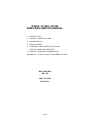
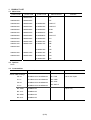
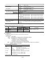
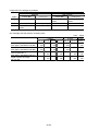
PIXMA iP1600
SERVICE
MANUAL
Canon
Copyright 2005, Canon U.S.A. This technical publication is the proprietary and confidential information of Canon U.S.A. which
shall be retained for reference purposes by Authorized Service Facilities of Canon U.S.A. Its unauthorized use is prohibited.
iP2200 / iP1600 / iP1200
SIMPLIFIED SERVICE MANUAL
1. PRODUCT LIST
2. PRODUCT SPECIFICATIONS
3. ERROR DISPLAY
4. SERVICE MODE
5. EXTERNAL VIEW / PARTS LIST (for Asia)
7. SPECIAL NOTES ON SERVICING
8. PRODUCT TECHNICAL INFORMATION
APPENDIX 2: iP2200 / iP1600 / iP1200 SERVICE TOOL
QY8-13AA-000
Rev. 00
June 30, 2005
Canon Inc.
(1/23)
1. PRODUCT LIST
1-1. Main Units
iP2200
product code
iP1600
product code
iP1200
product code
Sales territories
9989A001AA
US
9990A002AA
9989A002AA
CA
9990A003AA
9989A003AA
0196B003AA
LAM LVT
9990A004AA
9989A004AA
0196B004AA
LAM HVT
9990A006AA
9989A006AA
0196B006AA
EUM
9990A007AA
9989A007AA
0196B007AA
EMB
9990A008AA
9989A008AA
0196B008AA
ASA HVT
9990A009AA
9989A009AA
0196B009AA
AU
9990A010AA
9989A010AA
0196B010AA
KR
9990A011AA
9989A011AA
0196B011AA
GB
9990A012AA
Remarks
JP
0196B013AA
TW
9990A014AA
9989A014AA
0196B014AA
HK
9990A015AA
9989A015AA
0196B015AA
CN
0196B016AA
MY
1-2. Options
None
1-3. Consumables
Product name
Product code
Sales territories
Remarks
Canon FINE Cartridge
PG-40
0615B001AA to 0615B005AA
001: EUR
CL-41
0617B001AA to 0617B005AA
002: AMR
PG-50
0616B001AA to 0616B005AA
CL-51
0618B001AA to 0618B005AA
BC-70BK
0390B001AA
BC-71CL
0392B001AA
BC-90BK
0391B001AA
BC-91CL
0393B001AA
Other than Japan
003: ASIA
005: AMR S
Japan only
(2/23)
2. PRODUCT SPECIFICATIONS
2-1. Printer Main Unit Specifications
Paper feeding method
Resolution
Printing speed
Printing direction
Fast mode print duty
Print width
Interface
Supported ink cartridge
No. of pages that can be printed
ASF stacking capacity
Paper weight
Plain paper
High Resolution Paper
Glossy Photo Paper
Photo Paper Pro,
Photo Paper Plus Glossy,
Matte Photo Paper
Photo Paper Plus Double Sided
Photo Paper Plus Semi-gloss
Transparency
Envelope
T-shirt Transfer
Photo Stickers
Borderless printing
Detection function
Cover open
Presence of ink cartridge
Presence of ink
Presence of paper
Paper width
Waste ink absorber full
Internal temperature
Remaining ink amount
Print head alignment
Acoustic noise level
Fine (Photo Paper Pro / Fine mode)
HQ
ASF
4,800 x 1,200 dpi (max.)
iP2200:
Approx. 55 sec.
(PP-101, 4 x 6, borderless printing, default print quality)
iP1600, iP1200: Approx. 70 sec.
(PP-101, 4 x 6, borderless printing, default print quality)
For reference:
Fast
Standard
iP2200: Black
22 ppm
13.4 ppm
Color
17 ppm
7.8 ppm
iP1600: Black
19 ppm
13.4 ppm
Color
16 ppm
7.8 ppm
iP1200: Black
11 ppm
5.1 ppm
Color
11 ppm
4.2 ppm
Bi-directional / Uni-directional (automatically switched according to print data and
print mode)
50% duty
203.2 mm (216 mm in borderless printing)
USB (2.0) Full Speed only
Consumable
BK: 2,000 pages (1,500 character pattern)
CL: 1,600 pages (7.5% duty per color pattern)
80 pages (A4, photo, borderless printing)
200 pages (4x6, photo, borderless printing)
120 pages (Postcard, photo, borderless printing)
Max. 10 mm (Approx. 100 pages of 75 g/m2)
64 to 105 g/m2
10 mm or less
10 mm (Approx. 80 sheets) or less
A4, LTR:
10 sheets or less
4x6:
20 sheets or less
A4, LTR, 5x7:
4x6, 4x8:
10 sheets or less
20 sheets or less
1 sheet
A4, LTR:
10 sheets or less
4x6:
20 sheets or less
30 sheets or less
10 sheets or less
1 sheet
1 sheet
Up to A4, LTR
Available
Available
Available
Available
Not available
Available
Available
Available (Detected by dot counting)
Available (12 types)
Approx. 44 dB (Sound pressure level ISO9296)
Approx. 46 dB
(3/23)
HS
iP2000, iP1600: Approx. 58 dB
iP1200:
Approx. 56 dB
Environmental requirements
During operation
Temperature:
Humidity:
Temperature:
Humidity:
Non-operation
5C to 35C (41F to 95F)
10% to 90%RH (no condensation)
0C to 40C (32F to 104F)
5% to 95%RH (no condensation)
Power supply
Input voltage / Frequency
Power consumption: During printing
Stand-by status
External dimensions
Weight
Related standards
Electromagnetic radiance,
Electrical safety
AC 100 to 240 V, 50/60Hz
Approx. 10 W
Approx. 1 W
iP2200:
- With the paper support extended: Approx. 435 (W) x 280 (D) x 259 (H) mm
- With the paper support retracted: Approx. 435 (W) x 253 (D) x 165 (H) mm
iP1600, iP1200:
- With the paper support extended: Approx. 435 (W) x 277 (D) x 259 (H) mm
- With the paper support retracted: Approx. 435 (W) x 249 (D) x 165 (H) mm
Approx. 2.9 kg (excluding the ink cartridges)
VCCI, FCC, IC, CE Mark, Taiwan EMC, C-Tick, CCC (EMC), Korea MIC, Gost-R,
DENAN, UL, C-UL, CB Report, GS, FT, SASO, SPRING, Korea EK, IRAM
(Argentine)
Note: Not Blue Angel compliant.
<Difference between the iP2200, iP1600, and iP1200>
Ink cartridges
Housing
Model (main cover configuration)
Standard
Optional
iP2200 2 parts
PG-40, CL-41
PG-50, CL-51
iP1600 1 part
PG-40, CL-41
--iP1200 1 part
CL-41
PG-40
Throughput
iP2200 > iP1600 > iP1200
2-2. Product Life
Specified print volume or the years of use, whichever comes first.
- 3 years of use
- Print volume: 4,000 pages
- Black: 2,000 pages (A4, standard mode, 1,500 character pattern)
- Color: 1,600 pages (A4, 7.5% duty per color pattern)
80 pages (A4, photo, borderless printing)
200 pages (4 x 6, photo, borderless printing)
120 pages (Postcard, photo, borderless printing)
Note: The above print volume breakdown is estimated using average user consumption
patterns of printing 4,000 pages.
2-3. Ink Cartridge Specifications
Ink cartridge
Type
Ink-tank-integrated print head
Print head
Bk:
320 nozzles in 2 vertical lines
C/M/Y:
192 nozzles in 2 vertical lines per color
Ink droplet: Bk 30 pl, CL 5 pl / 2 pl
Ink color
Bk (pigment-based pearl), C/M/Y (super dye-based)
Weight
PG-40 approx. 43 g, CL-41 approx. 45 g
PG-50 approx. 51 g, CL-51 approx. 56 g
Supply method
As a consumable
(4/23)
<Supported ink cartridges by models>
Ink cartridge
Model
iP2200
iP1600
iP1200
Standard
PG-40 (BK)
CL-41 (CL)
Standard package
Standard package
Standard package
Usable as an
option
High capacity
PG-50 (BK)
CL-51 (CL)
Usable as an
Usable as an
option
option
Not usable
Not usable
Not usable
Not usable
Standard package
Standard package
<Ink cartridge (ink tank with the nozzles) yield>
Units: pages
iP2200
PG-40
1,500 character pattern
plain paper / standard mode (BK)
ISO JIS-SCID No. 5
plain paper / standard mode (BK)
ISO JIS-SCID No. 5
plain paper / standard mode (CL)
Digital camera 24 images
PP-101 4x6
CL-41
iP1600
PG-50
CL-51
PG-40
490
750
490
760
1,170
760
iP1200
CL-41
CL-41
430
-----
190
320
190
180
100
180
100
100
(5/23)
3. ERROR DISPLAY
Errors are displayed by the LEDs, and ink low warnings are displayed by the Status Monitor.
3-1. Operator Call Error (Alarm LED Blinking in Orange)
Alarm LED
Error
Corrective action
blinking
2 times
No paper
Set paper, and press the Resume/Cancel button
to feed the paper.
3 times
Paper jam
Remove the jammed paper, and press the
Resume/Cancel button.
4 times
No ink
Replace the ink cartridge(s), or press the
Resume/Cancel button to continue printing
without replacing the ink cartridge(s).
5 times
The ink cartridges are not properly
Install the ink cartridges properly.
installed, or a non-supported ink cartridge Or, confirm that the supported ink cartridges are
is installed (the ink cartridge EEPROM
installed.
data is abnormal).
7 times
Ink cartridge not installed
Install the ink cartridge(s), and close the access
cover.
8 times
Waste ink absorber full or platen waste ink Pressing the Resume/Cancel button will exit the
absorber full warning (approx. 95% of the
error, and enable printing.
maximum capacity)
14 times
Non-supported ink cartridge installed
Replace the non-supported ink cartridge with the
supported one.
16 times
Used ink cartridge installed, or no ink
Pressing the Resume/Cancel button will exit the
error, and enable printing.
3-2. Service Call Error (Cyclic Blinking in Orange (Alarm LED) and Green (Power LED))
Cycles of blinking
in orange and
Error
Corrective Action
green
2 times
Carriage error
Replace the printer as it has failed.
3 times
LF error
Replace the printer as it has failed.
7 times
Waste ink absorber full or platen waste ink
Replace the printer as it has failed.
absorber full
8 times
Print head temperature rise error
Replace the printer as it has failed.
9 times
EEPROM error
Replace the printer as it has failed.
10 times
No ink cartridge detected excepting ink
Replace the printer as it has failed.
cartridge replacement (during printing)
(6/23)
3-3. Ink Low Warning (Ink low warnings are displayed by the Status Monitor only when the
remaining ink level detection is enabled, and no Status Monitor display when disabled.)
Note: The Status Monitor display in the table below is for Windows.
Warning
Display by Status Monitor
Ink low warning 1 (approx. 70% of ink remaining)
Ink low warning 2 (approx. 40% of ink remaining)
Ink low warning 3 (low remaining ink)
Ink low warning 4 (no ink remaining)
(7/23)
4. SERVICE MODE
To conduct the following functions, a host computer (Windows 98 / ME / 2000 / XP), printer driver and
service tool (QY9-0068) for the iP2200, iP1600, and iP1200 are needed (though the stand-alone print
function is available).
If an error has occurred in the printer, the service tool cannot be used as it is. To use the service tool,
set the printer in the special mode, following the procedures below.
<Special mode setting procedures>
With the ink cartridges installed, while pressing and holding the Power button, connect the AC plug.
After the Power LED lights in green, with the Power button still pressed, press the Resume/Cancel
button 2 times, and release both the Power and Resume/Cancel buttons. (Each time the
Resume/Cancel button is pressed, the Alarm and Power LEDs light alternately, Alarm in orange
and Power in green, starting with Alarm LED.)
Function
Print head manual cleaning
<For reference>
Print head deep cleaning
Paper feed roller cleaning
Procedure
Remarks
Select “Cleaning” from the printer driver Maintenance.
Cleaning time: Approx. 40 sec.
Select “Deep Cleaning” from the printer driver
Maintenance.
Cleaning time: Approx. 60 sec.
Cleaning time: Approx. 2 min.
1. Remove the paper from the ASF.
Host computer is required.
2. Select “Roller Cleaning“ from the printer driver
Maintenance.
3. Following the instruction from the Status Monitor, load 3
sheets of plain paper in the ASF, and feed them.
Test printing
1) Nozzle check pattern printing Select “Nozzle Check“ from the printer driver
Maintenance.
<For reference>
1. Select “Print Head Alignment“ from the printer driver
Print head alignment
Maintenance.
2. Select the optimal value using the printed head position
adjustment pattern.
Nozzle check pattern printing
Significant misalignment can be
adjusted.
Host computer is required.
Refer to Shipment inspection pattern*1 below.
2) Shipment pattern printing
- ROM version
- Number of pages fed
- Waste ink amount
EEPROM reset
Refer to EEPROM reset / Destination setting*3 below.
(Reset of waste ink counter etc.)
Destination setting
Refer to EEPROM reset / Destination setting*3 below.
EEPROM information check
Stand-alone printing
Refer to Shipment inspection
pattern sample*2 below.
Host computer and service tool
are required.
Host computer and service tool
are required.
Host computer and service tool
are required.
Refer to Shipment inspection pattern sample*2 below.
Host computer and service tool
are required.
Host computer and service tool
1. Set paper.
2. In the stand-by mode, press the Resume/Cancel button NOT required.
5 times in 2 seconds.
<Conditions>
- At “no paper” error, turn the printer off, and turn it on
again, before doing the stand-alone printing.
- Even in the stand-by mode, if the printer enters the
power-saving mode (10 seconds after capping), the
stand-alone printing cannot be done.
*1 Shipment inspection pattern printing
a. Install the ink cartridge, and press the Power button to turn on the printer. (The Power LED lights in green.)
b. Set A4-sized paper.
c. Connect the printer to the computer. Using the iP2200 / iP1600 / iP1200 service tool (QY9-0068), select “USB
PORT.” (See APPENDIX 2, iP2200 / iP1600 / iP1200 SERVICE TOOL.)
d. Select “TEST PATTERN 1.” The printer starts printing the shipment inspection pattern.
(8/23)
*2 Shipment inspection pattern sample
EEPROM contents can be confirmed from the shipment inspection pattern printout (top of the shipment inspection
pattern). See APPENDIX 1, SHIPMENT INSPECTION PATTERN 1, for print sample.
*3 EEPROM reset / Destination setting
a. Install the ink cartridge, and press the Power button to turn on the printer. (The Power LED lights in green.)
b. Connect the printer to the computer. Using the iP2200 / iP1600 / iP1200 service tool (QY9-0068), select “USB
PORT”. (See APPENDIX 2, iP2200 / iP1600 / iP1200 SERVICE TOOL.)
c. <Destination setting>
Destination can be set by clicking “LOCK RELEASE,” then each model name in “SET DESTINATION.”
Confirm the model name by clicking “GET DEVICE ID” after setting change. (If incorrect, it can be changed before
turning the unit OFF/ON.)
<EEPROM reset>
When ”EEPROM CLEAR” is checked, the EEPROM is reset after the shipment inspection pattern printing.
(9/23)
5. EXTERNAL VIEW / PARTS LIST (for Asia)
5-1. External Parts, Power Supply Unit, Logic Board Ass’y
5-2. Print Unit
(10/23)
Parts List
Key
1
Part Number
Rank
Q’ty
QC1-6119-000
J
1
Description
ASF COVER
Remark
Common
parts
iP2200
QC1-6092-000
J
1
ASF COVER
iP1600, iP1200
QC1-6024-000
J
1
ACCESS COVER (E)
iP2200
QC1-6142-000
J
1
ACCESS COVER (J)
iP2200
QC1-6093-000
J
1
ACCESS COVER
iP1600, iP1200
QC1-6025-000
J
1
FRONT PANEL
iP2200
QM2-2139-000
J
1
MAIN COVER UNIT
iP2200
QM2-2125-000
J
1
MAIN COVER UNIT
iP1600, iP1200
QC1-5005-000
J
1
EMBLEM (E)
QC1-5009-000
J
1
EMBLEM (J)
6
QM2-2776-000
I
1
LOGIC BOARD ASS’Y
7
QC1-6015-000
I
1
TIMING SLIT STRIP FILM
Y
8
QC1-6016-000
I
1
TIMING SLIT STRIP FILM SPRING
Y
Y
2
3
4
5
Y
Y
9
QM2-2137-000
J
1
CAP BLADE UNIT
10
QC1-6021-000
J
1
CAP SLIDE SPRING
Y
11
QC1-6033-000
I
1
INK ABSORBER
Y
12
QC1-6034-000
I
1
INK ABSORBER L
Y
13
QC1-6088-000
I
1
INK ABSORBER R
Y
14
QC1-6014-000
I
1
PLATEN ABSORBER
Y
QK1-1543-000
I
1
AC ADAPTER: 100/240V 50/60HZ
QK1-1540-000
I
1
AC ADAPTER: 100/240V 50/60HZ
iP1600, iP1200
QC1-6108-000
G
SCREW, B-TIGHT M3x44
For main chassis to separation base
Y
Y
15
S1
iP2200
S2
XA9-1493-000
G
SCREW, TP M3x8
For base, main chassis, LF side plate
S3
XB1-2200-505
G
SCREW, MACH, TRUSS HEAD M2x5
For LF sensor to LF sensor plate
Y
S4
XB1-2260-305
G
SCREW, MACH, TRUSS HEAD M2 6x3
For main chassis to LF motor
Y
S5
XB1-2300-605
G
SCREW, MACHINE M3x6
For PE sensor to main chassis
Y
S6
XB6-7300-605
G
SCREW, TP, M3x6
For power supply, LF sensor plate
Y
Power cables:
QH2-2720-000
S
1
CORD, POWER
120V (LAM-LV)
QK1-0286-000
S
1
CORD, POWER
100V-120V (JP)
QK1-0278-000
S
1
CORD, POWER
100V-120V (US)
QK1-2017-000
S
1
CORD, POWER
100V-120V (TW)
Y
QK1-0279-000
S
1
CORD, POWER
220V-240V (EUR)
Y
QK1-1061-000
S
1
CORD, POWER
220V-240V (AU)
Y
WT3-5156-000
S
1
CORD, POWER
220V-240V (GB, HK)
Y
WT3-5160-000
S
1
CORD, POWER
220V-240V (KR)
Y
WT3-5182-000
S
1
CORD, POWER
220V-240V (CHN)
Y
Y: In common with the iP2200, iP1600, and iP1200
(11/23)
Y
Y
6. TROUBLESHOOTING FLOWCHART
6-1. Printer Main Unit Troubleshooting Flowchart (how to confirm printer operation at refurbishment)
Power ON
Service Call
Error?
Yes
No
Open access cover,
and install print head
Service Call
Error?
Yes
No
Connect to computer
Shipment inspection
pattern printing
Correct?
Yes
< Shipment inspection pattern check items>
(See APPENDIX 1, SHIPMENT INSPECTION PATTERN 1.)
See 4. SERVICE MODE for
printing method.
1. Non-ejection of ink:
2. Top of form:
3. Vertical lines:
4. Gray area:
No
Replace print head and print
shipment inspection pattern
Correct?
Yes
Off the paper
Not connected
White lines / uneven density
No
Yes
Main waste ink counter
less than 7%?
Yes
No
Visually check the platen waste ink
absorber, and replace it if it is
soiled.
Normal
Defective
<Note for normal printer refurbishment>
At end of refurbishment, set the printer to the default shipment conditions (with the paper lifting plate
in the raised position, and the carriage locked in the home position), following the steps below.
1. Install the ink cartridges, and while pressing and holding the Power button, connect the AC plug.
After the Power LED lights in green, with the Power button still pressed, press the
Resume/Cancel button 2 times, and release both the Power and Resume/Cancel buttons. (Each
time the Resume/Cancel button is pressed, the Alarm and Power LEDs light alternately, Alarm
in orange and Power in green, starting with Alarm LED.)
2. Print the shipment inspection pattern, and reset the EEPROM, following the procedures in 4.
SERVICE MODE.
3. Press the Power button to turn off the printer. (The paper lifting plate is raised, and the carriage
moves to the print head replacement position.) Remove the ink cartridges. (DO NOT print after
this point.)
(12/23)
NG
NG
NG
NG
6-2. Ink Cartridge Troubleshooting Flowchart (ink cartridge operation confirmation)
Connect to computer
Nozzle check pattern printing
See 4. SERVICE MODE
for printing method.
Yes
Correct?
No
See 4. SERVICE MODE
for cleaning method.
Ink cartridge cleaning
Nozzle check pattern printing
Yes
Correct?
No
Ink cartridge deep cleaning
See 4. SERVICE MODE
for cleaning method.
Nozzle check pattern printing
Correct?
Yes
No
Ink cartridge deep cleaning
Nozzle check pattern printing
Correct?
Yes
No
Replace ink cartridges
Nozzle check pattern printing
Correct?
Yes
No
Normal
Defective
(13/23)
7. SPECIAL NOTES ON SERVICING
7-1. Resetting the Main and Platen Waste Ink Counters
The counters for the main waste ink absorber and the platen waste ink absorber can be reset
separately. At waste ink absorber replacement, using the iP2200 / iP1600 / iP1200 service tool,
reset the applicable waste ink counter(s). (When both the main and platen waste ink absorbers are
replaced, reset both the main and platen waste ink counters.)
If an error has occurred in the printer, the service tool cannot be used as it is. To use the service tool,
set the printer in the special mode, following the “special mode setting procedures” in 4. SERVICE
MODE.
<Waste ink absorber replacement procedures>
1. Error check
At a waste ink full error (95% or full), identify which waste ink absorber is full, the main or the
platen, using the iP2200 / iP1600 / iP1200 service tool’s EEP-ROM INFORMATION, Dd or Ds
values, as the error itself does not indicate which waste ink absorber is full. (See APPENDIX 2,
iP2200 / iP1600 / iP1200 SERVICE TOOL, for details). Then, replace the applicable waste ink
absorber.
- Dd: Main waste ink absorber amount (120,080 mg at 95% full, 126,400 mg at full)
- Ds: Platen waste ink absorber amount (17,955 mg at 95% full, 18,900 mg at full)
2. Resetting the replaced waste ink absorber counter
- At main waste ink absorber replacement:
In the iP2200 / iP1600 / iP1200 service tool CLEAR WASTE INK COUNTER section,
click MAIN to reset the main waste ink counter value.
- At platen waste ink absorber replacement:
In the iP2200 / iP1600 / iP1200 service tool CLEAR WASTE INK COUNTER section,
click PLATEN to reset the platen waste ink counter value.
7-2. Servicing in Asia
- Elimination of Major Component Connectors on the Logic Board Ass’y In the models (iP2200, iP1600, and iP1200), the PE sensor, ASF sensor, and LF encoder sensor are
soldered to the logic board ass’y; thereby, the connectors which were used in prior models are
eliminated.
<Special notes on servicing>
In replacing the logic board ass’y, remove the solder from the PE sensor, ASF sensor, and LF
encoder sensor cable connections, and re-solder them to the replaced logic board ass’y.
Logic Board Ass’y
(14/23)
(15/23)
8. PRODUCT TECHNICAL INFORMATION
8-1. FAQ (Problems specific to the iP2200, iP1600, and iP1200, and their corrective actions)
No.
1
*
A
2
A
3
B
4
5
Function
Phenomenon
Possible Call / Claim
Corrective action
Installation Carriage error (Alarm and Power - The LEDs blink alternately in orange Remove the packing material fixing the
and green, 2 times (carriage error). carriage.
LEDs blink alternately 2 times).
Ink cartridge installation error
(Alarm LED blinks in orange 5
times.)
Cause
The user may not have removed the
packing material at unpacking and
installation.
Note: Even if the packing material
remains, no parts are damaged.
Open the access cover, and install the ink The user did not install the ink cartridges
- LED blinks in orange 5 times (ink
completely at unpacking, installation, or
cartridge installation error). (As this cartridge(s) properly.
ink cartridge replacement.
occurs at printer installation, the user
A non-supported ink cartridge is installed.
cannot recognize the error.)
No paper feeding
(Inkjet postcard)
- Paper out error
- Paper cannot be fed
- Cannot print
C
Multi-feeding
- Multiple sheets of paper are fed
simultaneously.
-Blank paper is ejected.
B
Envelope not feeding
- Paper out error
- Paper cannot be fed
- Cannot print
Paper
feeding
1. Perform roller cleaning from the printer
driver.
2. Clean the paper feed roller with
pre-moistened wipe or moistened
cloth.
1. Fan the paper and set them in the
ASF.
2. In case of PR-101, set the paper sheet
by sheet in the ASF.
1.
2.
3.
6
C
Paper jam
4.
1.
- Paper jam error
- Paper cannot be fed
- Cannot print
(16/23)
The paper feed roller slips on the paper at
paper feeding.
In the high temperature and high humidity
environment, the frictional force between
the front and back sides of paper
becomes high, and sheets stick to each
other, contributing to multi-feeding.
Perform roller cleaning from the printer The paper feed roller slips on the paper at
paper feeding.
driver.
Note: Depending on the paper lots.
Clean the paper feed roller with
pre-moistened wipe or moistened
cloth.
Reduce the number of envelopes
loaded in the ASF.
Flatten the envelope (with a pen).
Remove the jammed paper from the
As the LF roller slips on the paper, the
paper pick-up side.
paper is not fed, causing the jam error at
paper ejecting.
(8-1. FAQ (Problems specific to the iP1000 and corrective actions) cont’d)
No.
7
*
B
8
Function
Image
quality
Phenomenon
Smearing on printed side.
Possible Call / Claim
- Smear on the printed side of paper
- Cannot print properly
- Paper edge crease
B
Smearing on the backside, or
address side of postcards
9
C
Horizontal lines or uneven print
density at the trailing edge of
paper
<Photo Paper Plus Double Sided>
- Smears on the already printed side
when printing the other side
<When printing the address side of
postcards>
- Smears on the address side
<When printing the message side of
postcards>
- Smears on the backside
1. Recommend printing in the print
- Cannot print to the bottom edge of
quality assurance area.
paper
- Lines or uneven print density appear 2. Change the print quality from Standard
to High mode.
in the trailing edge of paper
3. Try other paper (PP-101)
- Cannot print properly
10
C
Horizontal lines or uneven print
density due to LF roller feeding
at small pitch
- Lines or uneven print density (on
skin tones and background)
- Cannot print properly
Corrective action
1. Correct the paper curl.
2. Recommend the user to conduct
printing in the print quality assurance
area.
1. Perform bottom plate cleaning from
the printer driver.
2. Clean the ribs on the platen with
cotton swabs/buds.
When the paper end comes off the pinch
roller, printing is performed without the
paper being held, preventing the ink
drops from being ejected in the correct
positions, resulting in unevenness.
Note: The problem is less noticeable
than that of the iP1500.
As the print media slightly slips while
1. Perform print head alignment.
2. Change the print quality from Standard being fed by the LF roller, printed areas
overlap, causing the problem.
to High mode.
*Occurrence level:
A: The phenomenon is likely to occur frequently. (Caution required).
B: The phenomenon may occur under certain conditions, but likeliness is assumed very low in practical usage.
C: The phenomenon is unlikely to be recognized by the user, and no practical issues are assumed.
(17/23)
Cause
The edge of paper rises due when paper
is curled, causing the ink cartridge to rub
against the printed surface of paper,
resulting in smearing.
When borderless printing is conducted
continuously, ink mist attaches to the ribs
on the platen, and is transferred to the
backside of the following paper.
8-2. Major Functions
(1) Paper thickness lever (at the bottom front of the printer)
The head-to-paper distance can be adjusted using the paper thickness lever.
<Possible problems with this function>
- The ink cartridge rubs against the paper when the amount of paper curl is large.
-> Flatten curled paper (to less than 3 mm).
-> In print modes other than borderless printing, conduct printing in the print quality assurance
area of the top and bottom edges. (Top margin 38.3 mm, bottom margin 31.2 mm)
(2) Quiet mode
The printer has a quiet mode function.
Compared with the normal mode,
Acoustic noise level:
Slightly lower. (HQ normal approx. 43.7 dB, Quiet approx. 42.8 dB)
Audible overtone level: Sound quality changes, and sound becomes quieter.
Print speed:
Slows.
<Possible problems with this function>
- The operation sound does not become quieter.
-> The audible sound becomes only slightly quieter.
- Printing is slow.
-> Disable the Quiet mode.
(3) Remaining ink level detection function
The printer has a function to detect the remaining ink level.
Detection method: Dot counting (Counted for each BK/CL ink cartridge)
CL cartridge: The remaining ink level is detected by total counted dot values
of 3 colors of ink.
Display method: Displayed on the Status Monitor (at 4 levels listed below for each BK/CL ink
cartridge)
Level 1: Approx. 70% of ink remaining
Level 2: Approx. 40% of ink remaining
Level 3: Indication of “!” mark (Remaining ink level is low)
Level 4: Indication of “X” mark (No ink remaining)
Note: Remaining ink detection function displays the status only, and does not
cause errors.
Accuracy:
The margin of error of detection accuracy is +/-10% in normal printing.
The margin of error is likely to be large in the following specific print patterns:
When printing continuously using any one of the CMY colors of ink
-> As the remaining ink level is calculated by the counted dot value of the
least remaining ink of 3 colors, if any of the C/M/Y inks is heavily
consumed, the margin of error for remaining ink increases.
When performing continuous BK solid printing
-> With continuous printing, ink flow from the tank to the ink chamber can be
interrupted, after which ink remains unused in the tank.
<Possible problems with this function>
- When a once-used ink cartridge is installed, the actual remaining ink level is not detected, and an
error indicating the remaining ink amount is unknown occurs.
Pressing the Resume/Cancel button will clear the error, and printing can be done. However, the
function to detect the remaining ink amount is disabled (ink status is not displayed).
e.g.: An ink cartridge was once used in another printer.
(18/23)
A current ink cartridge is removed from the printer. -> A new ink cartridge is installed. ->
The removed ink cartridge is installed again after removing the new ink cartridge.
- Due to the specific print pattern, the actual remaining ink level does not match the indicated
remaining ink level.
This is because a detection error can be large in specific print patterns (such as continuous
printing using any one of the CMY colors of ink or continuous solid printing, etc.).
(4) Start of printing before receipt of the complete print data
The printer RAM is not enough to store the complete print data for 1 scanning, so printing starts before the
entire print data for 1 scanning is stored in the buffer.
<Possible problems with this function>
- Printing is slow.
- Lines or streaks appear on printouts.
-> Increase the print quality (from Standard to High).
(5) Deep cleaning
The printer has a deep cleaning (refreshing) function.
Deep cleaning (refreshing):
This is a deep cleaning function in order to resolve print failure due to ink clogging
the nozzles. (The black ink is pigment-based, and clogs easier than other
dye-based ink.)
Perform from the printer driver Maintenance.
<Possible problems with this function>
- Excessive ink consumption when conducting deep cleaning repeatedly. (The amount of ink used is
approx. 4 times the normal manual cleaning amount.)
<Reference> Cleaning types, amount of ink used, and time required
Cleaning type
Amount of ink used
Manual cleaning
Dot count cleaning
BK: Approx. 0.10 g
Timer cleaning (24 hours to 2 months)
CL: Approx. 0.10 g
CL ink cartridge replacement
Cleaning on arrival at user
BK ink cartridge replacement
BK: Approx. 0.15 g
Timer cleaning (2 to 3 months)
CL: Approx. 0.15 g
Cleaning when the print head is not capped at printer power on
Timer cleaning (3 to 6 months)
BK: Approx. 0.30 g
CL: Approx. 0.30 g
Deep cleaning
BK: Approx. 0.45 g
Timer cleaning (6 months or more)
CL: Approx. 0.45 g
Time required
Approx. 40 sec.
Approx. 45 sec.
Approx. 55 sec.
Approx. 60 sec.
(6) Print head alignment
The printer has a print head alignment function (print head position adjustment function). As it is not
necessary to perform print head alignment at setup or installation of the printer, the function is only briefly
introduced at installation.
Print head alignment: This is a function to correct displacements between the nozzle lines of the
print head, and incorrect print position at bi-directional printing.
The adjustment is conducted using the printed head position adjustment
pattern.
A: Alignment of cyan nozzle inclination
(19/23)
B: Alignment of cyan large nozzles in bi-directional printing
C: Alignment of cyan small nozzles in bi-directional printing
D: Alignment between cyan large and small nozzles
E: Alignment of magenta large nozzles in bi-directional printing
F: Alignment of magenta small nozzles in bi-directional printing
G: Alignment between magenta large and small nozzles
H: Alignment between black even and odd nozzles
I:
Alignment of black nozzle inclination
J: Alignment of black nozzles in bi-directional printing
K: Horizontal alignment between CL and BK chips
L: Vertical alignment between CL and BK chips
M: Alignment of yellow large nozzles in bi-directional printing
N: Alignment of yellow small nozzles in bi-directional printing
O: Alignment between yellow large and small nozzles
Perform from the printer driver Maintenance.
(At initial set-up by the user, notice to perform the print head alignment is
displayed in the Status Monitor.)
<Possible problems with this function>
- The line is not straight.
-> Perform print head alignment from the printer driver.
- Printout is granulated.
-> Perform print head alignment from the printer driver.
(20/23)
APPENDIX 1: SHIPMENT INSPECTION PATTERN 1
Check item 1 (Non-ejection of ink): Total area of the sample below
Check item 2 (Top of form)
EEPROM information print (A)
-> See below for details.
BK nozzle check pattern
C nozzle check pattern 5pl
M nozzle check pattern 5pl
Y nozzle check pattern 5pl
C nozzle check pattern 2pl
M nozzle check pattern 2pl
Y nozzle check pattern 2pl
Check item 3 (Gray area)
Check item 4 (Vertical lines)
EEPROM information print (B)
-> See below for details.
Paper size: A4
<EEPROM information print>
Model name
(A)
ROM version
IP1500 P=V X.XX Dd=XXX.X Ds=XXX.X Page=XXXX
BL=XXXX YY YY YY YY USB= (YYYYYY)
Platen ink absorber
waste ink amount (%)
Main ink absorber
waste ink amount (%)
(B)
Dd=XXX.X Ds=XXX.X Page=XXXX PL=XXXX , PR=XXXX , CA=XXXX , BL=XXXX
SettingTime=XXXX / XX / XX XX:XX
Installation time
(21/23)
Number of sheets fed
Page: Total
PL:
Plain paper
PR: PR-101, PP-101, MP-101
CA: Postcard, inkjet postcard,
glossy photo card
BL:
Borderless printing (counted
separately from the count by
paper type)
APPENDIX 2:
iP2200 / iP1600 / iP1200 SERVICE TOOL
<How to use the iP2200 / iP1600 / iP1200 Service Tool (QY9-0068)>
Usage:
Shipment inspection pattern printing
Destination setting in EEPROM
EEPROM reset
Supported OS:
Windows 98 / ME / 2000 / XP (J/E version) : QY9-0068
Distribution method: Provided by SSIS (Download “iP2200 / iP1600 / iP1200 Service Tool” from
software download in SSIS.)
<Usage procedures>
1. Unzip iP2200_iP1600_iP1200ServiceTool.zip. (Double-click to unzip the file.)
2. Open the iP2200_iP1600_iP1200ServiceTool folder created after unzipping.
3. Open GeneralTool.exe.
A
B
F
G
C2
D
H
E
C1
4.
Select the connected USB port number from USB PORT (A).
<How to print the shipment inspection pattern>
1. Select TEST PATTERN 1 (B), and the shipment inspection pattern 1 will be printed.
(Refer to APPENDIX 1, SHIPMENT INSPECTION PATTERN 1.)
<How to set the destination>
1. Click LOCK RELEASE (C1), and select the applicable model name in SET DESTINATION (C2).
“iP2200J” for iP2200 Japan model
“iP2200E” for iP2200 non-Japan models
“iP1600E” for iP1600 non-Japan models
“iP1200E” for iP1200 non-Japan models
2. Click DEVICE ID (D), and confirm the model name indicated in the (E) area. Or, confirm the model
name on the shipment inspection pattern printout.
<How to reset EEPROM>
After marking the EEPROM CLEAR check box (F), perform the shipment inspection pattern printing.
The EEPROM will be reset.
(22/23)
<How to reset the waste ink counter>
In CLEAR WASTE INK COUNTER (G), select MAIN or PLATEN. The selected waste ink counter will be
reset.
MAIN resets the main waste ink counter.
PLATEN resets the platen waste ink counter.
If both the main and platen waste ink absorbers are replaced, reset both the main and platen waste ink
counters.
<How to confirm EEPROM information details>
Click EEP-ROM INFORMATION (H). The EEP-ROM INFORMATION dialog box will open to display
EEPROM information details.
(23/23)