1
MODEL NO=
113,201170
Serial
Number ...................................
Model and serial
number may be found
on the back
of the cabinet,
You should
record both
model and serial number
in a safe place for
future use,,
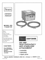
300 AMP
HiGH FREQUENC
ARC STABILIZER
A TTA CHMENT
CAUTmON:
Read GENERAL
and ADDITIONAL
SAFETY
® assembly
iNSTRUCTIONS
® operating
carefully
® repair
Sold by SEARS,
Part No. 61445
Y
ROEBUCK
AND
parts
CO., Chicago,
IL. 60684
U.S.A.
Printed in USA
SAFETY iNSTRUCTiONS
FOR ALL ARC WELDING
power supply
electrician
Protect yourself
and others
Failure to follow these
instructions
may result in serious personal
injury
FUMES AND GASES
MAY BE DANGEROUS
TO
YOUR HEALTH
ARC RAYS CAN INJURE
EYES AND BURN SKIN
ELECTRIC
SHOCK CAN KILL
WELDtNG
SPARKS CAN CAUSE EXPLOSION
OR
FIRE
Read and observe
all instructions
included
in this
manual
as welt as the following
specific
safety
precautions,
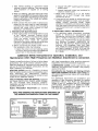
1. PROTECTION
FROM ELECTRICAL
SHOCK
g
WORK
CLAMP
AND
WORK
ELECTRODE
PIECE
HOLDER
METAL
TABLE
Up to 80 Volts A,C, or 100 Volts D.C. exist
between these parts when welder is onl
b
c.
d.
e
f,
and obtain
help frorn a qualified
Do not drop
or insert
objects
through
the
cooling louvers in the welding cabinet
It these
objects contact the internal parts of the welder
they could damage the welder or result in an
electrically
hazardous
condition,
2. EYE AND BODY PROTECTION
a Use helmet, filter, and cover plate complying
with ANSI Z87 1 to protect your- eyes and face
from sparks and the rays of the arc when
welding or observing open arc welding
b Always wear safety goggles with side shields
complying with ANSI Z87 1 when in a welding
area or when near a slag chipping operation
c Wear oil-free flame resistant protective garments,
such as leather' gloves, hearty long sleeved shirt,
cufftess trousers and high shoes. See picture of
appropriate dress in "Arc Weld it Yourself" section
of Welder' Owner's Manual
d. Protect other nearby personnel with suitable
non-flammable screening,
e Welding can produce fumes and gases wr_Jclq
are dangerous to health Keep your head out of
the fumes Use enough ventilation, exhaust at
the arc, or both, to keep fumes and gases from
your breathing zone and the general area
Take even greater care when welding on
galvanized or cadmium plated steel and other
metals
which
produce
toxic
fumes
Air-Supplied
helmets may be necessary.
f Protect yourself against a fall should you
receive an electric shock, particularly when
working above floor level Keep floor-around
your operating position free of clutter Never
wrap the electrode cable around any part of
your body
g Do not weld in locations close to chlorinated
hydrocarbon vapors coming from degreasing.
cleaning or-spraying operations
The heat of
the rays of the arc can react with solvent vapors
to form phosgene a highly toxic gas and other
irritating products
h Unprotected spectators must keep clear of the
welding area due to the harmful nature of
ultra-violet
and infra-red arc rays, welding
sparks, and welding fumes and gases
a. Never permit the electrode
or live metal parts
of the electrode
holder to touch bare skin or
any damp or-wet
covering
of the body
The
e_ectrode
coating
should be considered
as an
electrical
conductor
Do not insert electrode
in
electrode
holder- with your bare hand -- wear
proper gloves on both hands
ELECTRODE
TO OPERATOR
OPERATIONS
Wear dry hole4ree clothing, gloves and shoes
to protect and insulate the body
Take special care to insulate yourself from
ground
using dry insulation
(such as dry
wood) of adequate size when welding on metal
floors or gratings, and in positions (such as
sitting or lying) where parts or large areas of
your body can be in contact with possible
grounds
Turn switch "OFF" and remove plug from
power source before picking up or moving the
welder'.
Maintain the electrode holder, work cramp,
welding cable and welding machine in good,
safe
operating
condition
by practicing
periodic
inspection
and
preventative
maintenance.
This welder is not suitable for use under
electrically hazardous conditions due to water
or perspiration
Under these conditions
automatic
control equipment
is required in
accordance
with ANSI Z-49 I "SAFETY IN
WELDING AND CUTT1NG "
Connect the welder only to a source of
electrical power meeting the requirements,
including grounding, of the National Electrical
Code (ANSI C1) and local codes..
Improperly wired extension cords can cause a
potentially fatal shock hazard by electrically
energizing the welder cabinet Use only a properly wired and adequately sized extension cord
which has a grounded conductor-
3o FIRE AND EXPLOSION
a Remove flammable and explosive material at
least 35 feet from the welding arc to prevent
welding sparks or molten metal from starting a
fire Keep a type ABC fire extinguisher within
easy reach
b WeFding on or near containers which hold or
have held combustibles
can cause
an
explosion even when they have been cleaned
Do not weld on such containers until you have
read "Recommended
Safe Practices
for
Welding and Cutting Containers and Piping
That Have Held Hazardous Substances" F4 t
available from the American Welding Society
550 LeJeune Road Miami FL 33135
If you receive a shock from the welder cabinet,
immediately
disconnect
the welder
from the
2
C.
Vent hollow
castings
or containers
before
heating, cutting, or welding, They may explode
from
expansion
of trapped
air or boiling
liquids.
d When not welding,
place the electrode
holder
where it is insulated from the work clamp, work
piece, or work table, Accidental
grounding
can
cause overheating
of the cables and welder,
creating
a fire hazard
e, Never connect
the work cable or clamp to any
object but the work piece or metal worktable
Connecting
to other objects
such as building
ground
can cause
stray
currents
to flow,
resulting
in overheating
or fire
4. PREVENTATIVE
MAINTENANCE
a Never apply power to the welder with any part
of the "cabinet"
removed
Position
on-off
switch in "off" position
and disconnect
welder
from
the
power
supply
before
doing
maintenance
work
inside
the
machine
Removal
of the welder cabinet should be done
only by a qualified
service technician
b Before connecting
the welder
power cord to
the receptacle,
check the following:
1, inspect the power cord and welding cables
for Cuts or burns and make sure blades and
ground
pin on the plug are straight
2 Inspect "ON-OFF"
switch tever for cracks or
broken parts
3.. inspect
electrode
holder jaw insulators
for
cracks or broken parts
c. Never weld
anything
on or to the welder
cabinet,
as a burn
through
may
cause
transformer
failure.
d
If any part of your welder is malfunctioning
or
has been damaged
or broken, such as switch,
cables,
helmet,
electrode
holder,
cease
operation
immediately
and disconnect
welder
from the power source and turn switch "OFF"
until the particular
part is properly
repaired or
replaced
5. ADDITIONAL
SAFETY
INFORMATION
a For additional
safety information,
purchase
copies
of "Practice
for Occupational
and
Educational
Eye and Face Protection"
(ANSI
Z87 1), "Safety in Welding
and Cutting"
(ANSI
Z49 1), and "Fire Prevention
in Use of Cutting
and Welding
Processes"
(ANSI/NFPA
No
51B) from the American
National
Standards
Institute,
1430 Broadway,
New York,
New
York, 10018. Purchase copies of "OSHA Safety
and Health Standard"
29 CFR 1910 from the
U,S Government
Printing Office, Washington,
D C, 20402,
Additional Safety instructions for Operation, installation,
and
Maintenance
when High Frequency Arc Stabilizer Attachment is connected.
Protect yourself and others, Failure to follow these
instructions
can cause serious personal injury
Read and observe all instructions in this manual as
well as the following specific precautions for the
High Frequency Arc Stabilizer.,
ELECTRIC SHOCK can kill. Possibility of shock
from the welder power source is increased by use of
High
Frequency
Arc
Stabilization,
Observe
maintenance DANGER precautions located on and
inside the Arc Stabilizer cabinet,
FAULTY INSTALLATION
OR SERVICE procedure
can cause electric shock hazard, welder damage,
fire, and increased
radio frequency
radiation,
Installation and service must be performed only by
qualified personnel
RADIO FREQUENCY
RADIATION
can interfere
with heart pacemakers, other sensitive electronic
equipment, and communications
equipment,
COMPRESSED GASES, usually used with the Arc
Stabilizer, can cause injury or death if not properly
used and handled,.
Exceeding the Gas Tungsten Arc Welding (GTAW)
REDUCED CURRENT OR DUTY Cycle ratings for
AC-output welding power supply can cause welder
damage or fire
For additional
information
on installation
and
operation of High Frequency Stabilized Arc welding
equipment
refer to "FCC Rules and Regulations,
Volume I1, part t8" available from US. Government
printing office, Washington D,C 20402 and "NEMA
Standard EW-t" available from NEMA, 2101 L St.,
N,W,, Suite 300, Washington DC., 20037,
READ AND OBSERVE THE INSTRUCTIONS
APPEARING ON
THE WARNING INFORMATION FOUND ON THE CABINET.
D_A_.{_ER:
_G_ VOLTAGE
INSIDE
...... OFARC_LIZEB
II
CANKILL.
II
TURN ARC STABILIZERAND WELDER OFF, G_IFLUG 1'RE
ARC STABILIZER. MtO RISCOBRECT TIlE ARC STABILIZER
FROM TIlE WELDING CABLtESBEFOREREMGVi_t.!, AltY
PART OF THE CABRET _tE_ER APPLY POWER 10 TOE ARC
WffH Ally PAnT OF TtfE CABINETRE f,_.R_ER
*In_.utSpectffc_U°ns:
11SVO!la
• ! _mp
MaN[mum wekfl_] cultet_t
300 tNmp__t 3P_%duly _:'/clr_
BEVBIZSE
GEl 1fO1"
THESE
@
{I
jj
j_
Jl
II
_,_
CABLES e_
phase
_v'_BN!_NG:
T_
w.,,o0
10 POLLOW 'IRESE IRSTOUCTIO_S MAY
RE,SULTtX SERIOUS PERSONAL IKJURT.
_¥ES.m_!D.G_ASES
CARBEGARERUUS
pRDTECT__NUnSEEF _RD O_ ER5 EARLOBE
[_
_WSEAnS,
'LOGO FFEALTtLA_C I'LA_'S_tI IIJJURE EYES
A_D BRRR SE1H. ELECTRIC SRQBK C/_R
riOEOOCV,A_DCO"
CAR CAO_SE
tP-JURY, ffADJDFAEOUE![C¥
PACEMAKERS, OTHER SERSII_'_fEELECTROniC
EOUIPMEUT, NtO COMMUIRCA_3OFlS,
T_ E_et:It_d_" ff_lder
Of GTAW Torch
t_IIUAL RiO IRStRUCtlORS SUPPLIED
WITH WELOIBG E_t._PMERT. tttERT GAS
EEGUL._ORS AND ASSOCIATEJ_
EGUIP,
READ AOR
UNDERSTARO
TI_E
OWOEff
S
MEHT_
WELDING
GUPPLtES
ARO
SAFETY
EO#tPMENT. S£S OWFlER'S MAFiGAL
FOX AVAILABILIW OF ftA_t0RAL SAErt
S_ARGARO_; BR[I COMMURCI,_:I'tOFFS
t_TERFEREFFCEREGDI._ORS
'Wm_ Ceb_e
Coneecti_n"
GAS T'dRGSTEN-ABC WELRO_GWILL REDDER TIlE
ALLOWABLE OUTPUT ARO DUW CYCLE DP AC
WELDERS. SEE OWNER'S MAHUAL.
! 00 NOT TOGDI{ LIVE EEEC]RICAL PARTS. RICLRROtD
THE WELO_RGCIRCUIT tRDR PFlEOUERCYERERGY
1_ THE WELOI_G CIRCLI]T IHCRCASESTIlE R_SI_OF
St!OCK, WEAn DRY HOLE-FUEEWELDER'S GLOVES.
RECOMMEFFRE£1
HELMET ARO LERB FULL BLOTHIRG
Afar SttOBS.
KEEPYOUR OE_O OUT OF THE FUMES, USE E_OUEtt
VEh'TILRRDH, EXItAUSY/IT TIlE ARC, On BOTH, TO
KEEPFUMES AF_R GASES FROM YOUR OREATHI_G ZOFlE
4 I_STALL TItIS UHIT AS I._I_RUCTED lit TI_E GWIiER'S
I_RUAL, IMPROPER IRSTALLATIO,_ICORRECTIOHS÷
OR ORGIJ'RRIHO_ll CAUSE Stt_CK ll/bT.AFIO,
WELOER
DAMAGE, Rifle ARO IRCREA.SERRA_IO FREQUENCY
I_OlkllOtL
5 COl_itECTOtILY TO A OOOURDIOG POWER SOURCE
CONFORMIng TO TIlE RA_IDHAL EEECTHiCAL COOS
ARC=LOCALCODES
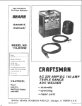
FULL ONE YEAR WARRANTY
ON CRAFTSMAN
ARC STABILIZER
if the Craftsman Arc Stabilizer fails to perform properly, due to a defect in material or workmanship, within one year
from the date of purchase, Sears will repair it free of charge. This warranty applies only while this product is in use in the
United States°
WARRANTY SERVICE iS AVAILABLE BY SIMPLY RETURNING THE ARC STABILIZER TO THE NEAREST SEARS STORE OR
SERVICE CENTER THROUGHOUT THE UNITED STATES_
This warranty gives you specific legal rights, and you may also have other rights which vary from state to state_
SEARS, ROEBUCK AND CO, DepL 698/731A, Sears Tower, Chicago, IL 60684
TABLE
OF CONTENTS
Connection
Safety Instructions to Operator
For all Arc Welding Operations
Safety Instructions for Operation, installation,
and Maintenance when High Frequency
Arc Stabilizer Attachment is connected
Warranty
Specifications
Getting to Know Your High Frequency
Arc Stabilizer
Unpack and Check Contents
Installation
Assembly
2
6
Power Supply
Minimizing RF Radiation
Certification
Maintenance
Operation
Gas-Tungsten Arc (GTAW) Welding
Welding with Conventional Electrodes
(Stick Welding)
Troubte-Sht)oting
Repair Parts
3
4
4
4
4
5
8
8
9
10
10
13
14
14
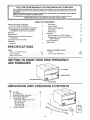
SPECIFICATIONS
Input
Volts AC (Single Phase) .......................
Hertz (cycles) ...............................
Rated Input Amps ...........................
Maximum Welding Current
Arnps ......................................
Duty Cycle (Maximum)
..................
115
60
1
300
30%
GETTING TO KNOW YOUR HiGH FREQUENCY
ARC $TABmLIZER
TORCH
=_ WORK CABLE
ON-OFF
SWITCH
TO WELDER
UNPACKING
Key
No,
1.
2
3
4
5.
AND CHECKING
PartName
Arc Stabilizer . ...................
Electrode Cable Assembly
.......
Work Cable Assembly ............
Loose Parts Bag
containing the following items:
Nut, Hex 1/4-20 ....................
Spring Washer o................
Terminal Lug ..........................
Plug Assembly
.................
Owners Manual .....................
CONTENTS
Qty,
1
1
1
5
1
1
1
1
1
4
aNSTALLATJON
installations using a High Frequency Arc Stabilizer
Attachment
will produce some radio frequency
radiation and will impose some high vottages on the
welder, The following installation instructions must
be followed carefully to minimize these effects°
WARNING: The voltages imposed on the welder by
a High Frequency Arc Stabilizer can damage the
welder° In addition, welding with the Gas-Tungsten
Arc (GTAW) process and AC welding current can
cause welder overheating. Install High Frequency
Arc Stabilizers only with welders recommended by
their manufacturer for use with High Frequency Arc
Stabilizers. Consult with the welder manufacturer
regarding
possible derating
or duty cycle
reductions if the welder is to be used for AC
Gas-Tungsten Arc (GTAW) Welding.
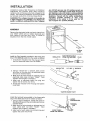
ASSEMBLY
Remove the electrode holder and work clamp from
your welder cables and cut welder electrode and
work cables to two feet long, Strip ,75 inches of
insulation from the end of each cable,
2 FEET
.75 INCH
STRIP
Install the Plug Assembly provided in the loose parts
bag on the electrode cable from the welder as follows:
INSULATOR
\
1. Unscrew the Insulator from the plug and place
over the electrode cable from the welder,
2. Using a 1/8 inch hex "L" wrench, back out the
set screw in the plug until the electrode cable
end can be inserted easily
3. Make sure the wire strands on stripped end of
electrode cable have not been "frayed", Twist
together with fingers if necessary,
4., Insert end of electrode cable into plug and
tighten the set screw very firmly
5 Thread the Insulator over the plug and tighten
hand tight,
ELECTRODE CABLE
FROM THE WELDER
INSULATOR
1/8" HEX "L" WRENCH
\
TIGHTEN
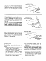
Install the terminal lug provided in the loose parts
bag on the work cable from the welder as follows:
1, Using a large screwdriver, loosen the screw in
the terminal lug until the work cable end can be
inserted easily.,
2., Make sure the wire strands on stripped end of
work cable have not been "frayed",
Twist
together with fingers if necessary
37 Insert end of work cable into terminal lug and
tighten the screw very firmly,
PLUG
HAND TIGHT
t
_--'__
WO _"__
FROM THE WELDER
LARGE
\ii_ SCREWDRIVER
TERMINAL
WORK CABLE
{SUPPLIED
WITH
ARC
STABILIZER)
Install the work clamp previously removed from
your welder work cable on the new work cable
supplied with your Arc Stabilizer
according
to
instructions
provided with your welder or work
clamp The work cable supplied has terminals for
bolted connections
on both end&
e_
I
If the Arc Stabilizer is to be used for Gas-Tungsten
Arc (GTAW) Welding, install the GTAWtorch on the
bare end of the electrode cable supplied with your
Arc Stabilizer according to instructions
provided
with the GTAW torch. The electrode cable supplied
has a plug on one end and is stripped bare on the
other end.
YOUR WORK
CLAMP
ELECTRODE CABLE
(SUPPLIED
WITH
ARC
1
STABILIZER)
CAUTION: The GTAW torch also has provisions for
connecting to a source of shielding gas° This must
be done in accordance with instructions supplied
with the GTAW torch, hoses, regulators, and gas
cylinders and is not covered in this owner's manual.
ELECTRODE
HOLDER
/'_
GTAW TOR
ELECTRODE CABLE
(SUPPLIED
WITH
ARC STABILIZER)
If the Arc Stabilizer is to be used for conventional
covered electrode
welding, install the electrode
holder removed from your welder electrode cable
on the electrode cable supplied with your Arc
Stabilizer according to instructions
provided with
your welder or electrode holder-.
"_
CONNECTIONS
The High
connected
follows:
Frequency
Arc Stabilizer
to the welder' and welding
_ _
YOUR ELECTRODE
HOLDER
5, Do not overtighten,
but secure the two work
cables to the "Work Cable Connection"
stud
using the nut and Iockwasher supplied and a
7/16 wrench_
must be
cables as
CAUTION: Excessive torque on the "Work Cable
Connection" stud can break the insulator. Use two
7/16 wrenches, one to tighten the connection and
one to restrain the existing nut on the stud, so
excessive force is not transmitted to the insulator.
1 Plug the electrode cable from the welder into the
"To Welder" jack of the Arc Stabilizer-,
2, Plug the electrode cable supplied into the "To
GTAW Torch" jack of the Arc Stabilizer
6. Connections to a DC or AC/DC welder are the
same as to an AC welder except that DC or
AC/DC welders are provided with jacks so that
the electrode cable can be plugged into either
the positive or negative jack to make the
electrode positive (reverse polarity) or electrode
negative (straight polarity),
3, Place the terminal lug on the end of the work
cable from the wetder onto the "Work Cable
Connection" stud of the Arc Stabilizer,.
4, Place the terminal on the free end of the work
cable
supplied
onto
the "Work
Cable
Connection" stud of the Arc Stabilizer.
6
ARC
WELDER
H_GH FREQUENCY
ARC STABiLiZER
DO NOT REVERSE
THESE CONNECTIONS
JACK
'TOGTAWTORO._'\
JACK
GROUND
CABLE CONNECTION
WORK
L
CABLE
2 FEET LONG
ELECTRODE
CABLE
WORK
ELECTRODE
CABLE
CABLE
DETAIL OF
WORK CABL_
CONNECTION
CONNECTIONS
TO AN AC WELDER
OR AC/DC
HiGH
ARC
WELDER
CONNECTIONS TO A DC
OR AC/DC WELDER
FREQUENCY
STABILIZER
ELECTRODE NEGATIVE
GROUND
/
@
WORK
CABLE
t
2 FEET LONG
ELECTRODE
DC OR AC!DC
CABLE
WELDER
HIGH FREQUENCY
ARC STARLtZER
2 FEET
ELECTRODE POSITIVE
LONG
7
ELECTRODE
CABLE
POWER
SUPPLY
Connect the Arc Stabilizer toa 115volt, 60hz, singte
phase, 15 or' 20 ampere grounding receptacle.. All
wiring must comply with the National Electric Code
(ANSI C1) and local codes Refer tothe "Minimizing
RF Radiation" section of this manual for proper
power supply shietding practices.
NOTE: When the Arc Stabilizer is used with single
phase welders, the Arc Stabilizer- and welder must
be supplied from the same phase of the power
supply
Unsatisfactory
performance
may result if
the Arc Stabilizer and welder are supplied from
different phases.
MINIMIZING
RF RADIATION
These instructions
must be followed exactly for
installation to comply with FCC Regulations.
General
High Frequency Arc Stabilizer installations
will
produce some radio frequency
electromagnetic
radiation.. Such RF Radiation, if the signal strength
is sufficient
at the receiving device, can cause
inconvenience or disruption in communications
or
cause malfunction
in sensitive electronic controls
and systems or heart pacemakers. RF Radiation can
come from several sources
Direct Radiation from the High Frequency Arc
Stabilizer or Welder
Direct radiation is that radiation emanating directly
from the High Frequency Arc Stabilizer-or Welder.
Radiation
from power line and welding circuit
attachments is not considered to be direct radiation
from the High Frequency Arc Stabilizer or Welder:
Direct Radiation from the Welding Circuit
Any attachment to the output terminals of the high
frequency source is capable of acting as an antenna
and transmitting
radiation
Attachments
include
leads, torches, worktables, etc, either necessary or
unnecessary
Since direct
radiation
from
the
welding circuit is the major source of radiation, it is
important to keep attachments to a minimum
Conduction and Radiation from the Power Line
Most power lines are capable of conducting high
frequency energy which may cause interference
directly or by radiation from these power tines.. Most
conducted power fine radiation comes from direct
radiation
picked up by the power lines and
reradiated.. Normalty such interference is small
when compared to that caused by radiation from the
welding leads
Re-radiation
Radiation from the welding circuit can be picked up
by ungrounded metal objects or unshielded wiring
in the immediate vicinity, conducted some distance,
and reradiated. This can bea troublesome source of
interference
Power Supply Shielding
Power supply conductors for both the Arc Stabilizer
and the welder must be completely enclosed in solid
metallic conduit for a distance of at least 50 feet
away from the Arc Stabilizer, welder, and welding
arc Joints in the conduit must be firmly electrically
bonded
Flexible helically wrapped conduit is not suitable for
this purpose The conduit must be well grounded at
the farthest point away from the Arc Stabilizer and
wetder..
The conduit enclosing the Arc Stabilizer power
supply conductors
must extend to the receptacle
into which the High Frequency Arc Stabilizer is
plugged,.
When the welder has a flexible power cord, the
conduit
enclosing
the welder
power supply
conductors
must extend to the receptacle
into
which the welder is plugged,
When the welder is not provided with a flexible
power' cord, the conduit must extend to the welder
enclosure and be firmly electrically bonded to it.,
Enclosure Covers and Access Doors
When the Arc Stabilizer is in operation, all enclosure
covers and access doors must be in place and
properly fastened..
Miscellaneous Wiring
Unshielded miscellaneous wiring such as lighting,
power, telephone communication,
and other wiring
should be re-routed at least 50 feet away from the
Arc Stabilizer, welder, and welding arc. Where this is
not feasible, such wiring must be enclosed in solid
metallic conduit and grounded as described under
"Power Supply Shielding".
Miscellaneous Conducting Materials
Miscellaneous conducting materials should not be
located within 50 feet of the Arc Stabilizer, weeder,
and welding arc Such materials that can not be
excluded must be grounded.
Welding Leads
The welding leads should be kept as short as
possible and must not exceed 25 feet in length.
Eight foot Feads are provided with the Arc Stabilizer.
The werding leads should be kept as close together
as possible and should be kept as close to the
ground
or floor
as possible.
Unnecessary
attachments to the welding leads, such as spare
torches or electrode holders, should not be used..
The magnitude of RF energy transmitted as well as
the frequency spectrum of such transmission may
be altered substantially by changing the length or
position of the welding leads..
Grounding the Welding Circuit
The enclosure of the Arc Stabilizer must be well
grounded.. The preferred ground connection is to a
ground rod at least 8 feet long, driven into moist soil.
In locations
with low soil conductivity
the soil
around the ground rod should be moistened or'
treated with a salt solution.
A cold water pipe may be used in place of the
ground rod provided it enters the soil within 10 feet
of the Arc Stabilizer
The grounding connection to the Arc Stabilizer may
be made to one of the enclosure screws_ The
enclosure must be scraped free of paint under' the
screw_ All electrical connections must be made with
clear] bright metal surfaces
The lead connecting
the enclosure
of the Arc
Stabilizer to the ground rod or' water pipe must be as
short as possible. In no case shall the length of
conductor
between the enclosure
of the Arc
Stabilizer and the point where the ground rod or
water pipe enters the soil exceed ten feet=
Metal Buildings
Installing the High Frequency Arc Stabilizer within
an electrically bonded and grounded metal buirding
can be an effective means of reducing RF Radiation.
CERTIFICATION
FCC Regulations
High
Frequency
Stabilized
Arc
Welding
installations are required to meet radio frequency
radiation
limits
given
in the
Federal
Communications
Commission
(FCC) Rules and
Regulations, Part !8 Further, the FCC requires all
High
Frequency
Stabilized
Arc
Welding
installations to have certification.
Certification may
be based upon manufacturers tests, or upon actual
on site measurements.
interpret
radio frequency
radiation
measurements
The FCC requires that the signed certificate be
placed in a location
where it is conveniently
available
for
inspection
by authorized
representatives of the FCC The certificate may be
attached directly to the equipment or may be at
another location provided a notice is attached to the
equipment stating where the certificate is located
If certification
is based upon manufacturers tests,
the manufacturer
conducts
tests to verify
compliance with FCC requirements and provides
instructions for proper installation and operation of
the High Frequency Arc Stabilizer.. When the High
Frequency Stabilized Arc Welder installation has
been completed as specified by the manufacturer
and the equipment is being operated in accordance
with the manufacturer's
instructions,
the user so
stipulates by signing a certification form provided
by the manufacturer
Certification of your Installation
This Arc Stabilizer has complied with the tests
necessary
to permit certification
based upon
manufacturer's
tests. When the instalfation
is
completed,
the person
responsible
for the
installation and operation of the High Frequency
Stabilized Arc Welder Installation is required to sign
the certificate
included
in this owners madual,
attesting that the installation
has been made in
accordance
with the instructions
given in this
owners manual.
If certification
is based upon actuat on site
measurements,
the user is responsible
for
conducting
radio
frequency
radiation
measurements on the finished installation following
procedures
outlined
in the FCC Rules and
Regulations,
Part I8 A certificate must then be
executed by an individual qualified to make and
Responsibility
Conformance
with
FCC requirements
is the
responsibility of the user and the user is required to
take steps promptly to remedy any instances of
harmful interference
with any authorized
radio
service.
CERTIFICATION
OF HIGH FREQUENCY
ARC WELDER INSTALLATION
I HEREBY CERTIFY THAT:
I am familiar with the requirements of Part I8 of the FCC Rules pertaining
certificaton of High Frequency Stabilized Arc Welders; and
If harmful
and
interference arises, I will take prompt steps to eliminate
i have installed the equipment
Owners Manual
in exact accordance
By (signature):
Date:
9
to the operation
and
the harmful interference;
with the instructions
provided
in the
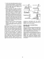
MAINTENANCE
Cables, Plugs, and Electrode Holder or GTAW
Torch
The high frequency voltage generated by a High
Frequency Arc Stabilizer tends to arc through
cracks, holes,and damp or weakened insulation in
welding cables, jacks, plugs, electrode holders or
GTAW torches. This can increase the risk of shock
from the up to 80 volts AC or 100 volts DC welding
voltage. Periodically
inspect for cracks, missing
parts, excess wear, or deterioration,
and replace
items found to be defective promptlyo
SET SCREWS
Spark Gap Setting and Adjustment
1. The spark gaps inside the Arc Stabilizer have
been pre-set at the factory. During operation
this setting will gradually
increase due to
erosion of the spark gap contacts, and should be
checked and re-adjusted after every 200 hours
of running time.. The cover must be removed
from the Arc Stabilizer to provide access to the
spark gaps.
FEELER GAGE
b Loosen the set screw that holds the two end
contacts.
c Select a reelergage (008 thick) and insert it in
the gaps between the two contacts as shown
d. Push the end contacts (one at a time) toward
the center fixed contact
until the gaps
between the contacts is the exact distance
determined by the feeler-gage
e._Tighten set screws, and install the cover
DANGER: This adjustment must be made only by
personnel
qualified
to perform
electrical
maintenance. High voltage exists inside the Arc
Stabilizer unless external power is disconnected.
Before removing the cover, always remove the plug
and cord of the Arc Stabilizer and welder from the
power line.
CAUTION: High-frequency
intensity and radio and
TV interference will increase as the gap setting
increases.Therefore,the
recommended gap setting
must not be exceeded.
Enclosure Covers
Enclosure cover-s on both the Arc Stabilizer and
welder must be installed and secured with all the
fasteners originally provided before connecting the
Arc Stabilizer or welder to the power line
2 Each spark gap should be set between 006 and
.010 inch._ The adjustment
procedure
is as
follows:
a. Remove the cover' (Refer to the exploded
parts drawing for parts locations.)
used for mild steel and other metals GTAW can be
used with DC electrode negative (straight polarity)
in which case the High Frequency Arc Stabilizer
aids arc starting, but may be turned off if desired
once the arc Is started.. DC electrode
positive
(reverse polarity) concentrates the arc heat on the
tungsten electrode and is seldom used for GTAW.
OPERATION
The high frequency voltage produced by a High
Frequency Arc Stabilizer
is sufficient
to spark
across a small gap between the electrode and the
work, creating an initial path of ionizaton that the
main arc current can follow.
High Frequency Arc Stabilizers are most frequently
used in conjunction
with Gas-Tungsten
Arc
(GTAW) Welding where they offer the advantages of
arc initiation
without
physically
touching
the
tungsten electrode to the workpiece and stabilizing
AC arcs to prevent erratic arcing or pop out
High Frequency Arc Stabilizers are also used with
conventional covered electrode welding wherethey
offer improved
arc stabitity,
particularly when
welding with hard to use electrodes such as tow
hydrogen and stainless steel
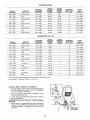
GAS-TUNGSTEN
ARC WELDING
Type of Gas Required
Argon
is recommended
for generaW purpose
welding. Argon is available in K-cylinders having a
capacity
of 238 cubic-feet
at a pressure of
approximately
2200 psi., or in T-cylinders having a
capacity
of 330 cubic-feet
at a pressure
of
approximately
2640 psi. Argon is commercially
available with a purity of 99.95% to 99.99%. The
higher purity is recommended for best results
Pressure Regulator and Flowmeter
An Argon pressure regulator and ftowmeter, or a
unit combining
these two items is required
The
flowmeter should read in cubic-feet per hour
Electrodes Used With GTAW Torch
For most general uses a 2% thoriated tungsten
electrode
shoutd be used. Tungsten electrode
diameters to be used with this High Frequency Arc
Stabilizer
are .040, t/16, 3/32, 1/8, 5/32 and
3/16-inch.
(GTAW)
Description of GTAW Process
GTAW uses the heat generated by an arc between a
tungsten electrode and the workpiece to melt the
workpiece
and create a weld. Filler metal, if
required, is supplied by a filler wire dipped into the
molten wetd puddle to melt off sufficient metal An
inert gas, usually argon, shields the molten weld
metal and tungsten electrode from the surrounding
atmosphere.
GTAW is most useful with AC welding current to
weld aluminum and stainress steel and can also be
GTAW Torch
Either a water-cooled or an air-cooled torch may be
used
CAUTION Do not exceed the current rating of the
torch or damage to the torch will result.
IO
Cleaningthe
Metal
Before welding
is begun, it is important
that
surfaces to be welded are clean Oil, grease, paint,
rust, dirt or other contaminants should be removed
in order to prevent gases produced from these
materials from contaminating
the inert-gas and
interfering
with a normally clean, smooth flow of
weld metal. These gases can cause porosity,
incomplete
fusion, inadequate
penetration,
and
under-cutting,
in addition to rough welds of poor
appearance
Recommended
Settings
BRASS
METAL
THICKNESS
t/16"
(.062-)
1/16 '° (,062")
Cleaning may be accomplished with liquid cleaners
and vapor, or mechanical methods, Liquid cleaners,
such as naphtha, mineral spirits, alcohol, acetone,
or methylethyl-ketone
may be used, Liquid cleaners
or solvents should not be used after a joint is
assembled All surfaces should be wiped dry with a
clean cloth Imbedded dirt may be removed with a
file, chisel, wire brush, etc., provided these tools are
clean and free of oil Grinding is not recommended
TYPE OF
WELD JOINT
Square
Groove
Fillet
1/8' (.125")
Square
1/8" (,125")
Fillet
3/16" {.18T')
Square
3/16"' (.187")
Fillet
I/4"
(.250)
Square
t/4"
(.250")
Fillet
Groove
Groove
Groove
TUNGSTEN
ELECTRODE
DIAMETER
ALLOYS
AC_HF
WELDING
CURRENT
(AMPS)
1/16" (.082-)
105_155
1/t6"
(.082-)
1/t6"
(,062")
DC*SP
WELDING
CURRENT
(AMPS)
SHIELDING
GAS-ARGON
CU.FTJHR.
FILLER
ROD
DIAMETER
85-125
15
1/!6"
(,062")
105-155
85_125
15
1/16" (,062")
145-t90
115-150
15
3/32" (.093")
1/16" (.062")
145-190
115-150
15
3/32'
3/32"" (.093")
180-200
145-195
20
3/32" (.093")
3/32"' (,093")
180-200
145-195
20
3/32" (,093")
3/32" (.093")
--
t60-200
25
t/8"
3/32" (.093")
--
160-200
25
1/8' (.125")
(,093)
(,125")
MILD STEEL
METAL
THICKNESS
TYPE OF
WELD JOINT
t/32"
(,03I")
Square
t/32"
(.03t")
Fillet
3/64" (.046")
Square
3/64" (.046)
Fillet
1/t6"' (.062")
Square
1/t6"' (.062")
Fillet
3/32" (.093")
Square
3/32" (.093')
Fillet
t/8'
(.125")
1/8'" (,t25")
Square
Groove
Groove
Groove
Groove
Groove
Filiet
TUNGSTEN
ELECTRODE
DIAMETER
AC-HF
WELDING
CURRENT
(AMPS)
DC*SP
WELDING
CURRENT
(AMPS)
1/16'" (_062")
95-125
75-100
10
1/16'" (°062")
1/16"' (.062")
95-125
75_100
10
1/t6"
(.062"')
1/16" (.062")
tt5-t50
90-120
10
1/16'
(.062)
1/16" (.062")
115-I50
90-120
10
1/16" (,062")
1/16'" (.062")
I20.170
95-135
10
1/16" (.062")
1/16"" (.062")
t20-t70
95-135
10
1/16" (,062")
3/32" (,093")
t70.200
135-I75
10
3/32" (.093")
3/32
(.093")
t70-200
135-!75
t0
3/32" (.093")
3/32" (.093-)
180-200
145-200
12
1/8
3/32-(.093")
t80-200
145-200
12
118" (.125")
ALUMINUM
METAL
THICKNESS
TYPE OF
WELD JOINT
SHIELDING
GAS-ARGON
CU. FT,/HR.
FILLER
ROD
DIAMETER
(.125")
ALLOYS
TUNGSTEN
ELECTRODE
DIAMETER
AC-HF
WELDING
CURRENT
(AMPS)
DC-SP
WELDING
CURRENT
(AMPS)
SHIELDING
GAS*ARGON
CU, FT,/HR,
FILLER
ROD
DIAMETER
3/64" (,046')
Square
Groove
1/16" (,082")
40-60
--
20
1/16" (,062")
1/t6"
(.062")
Square
Groove
3/32" (.093")
70.90
--
20
3/32" (,093")
!/16"
(.062")
Filter
3/32" (,093")
70-90
--
t5
3/32" (,093")
3/32" (.093")
90-1t5
--
20
3/32" (,093")
3/32-(.093")
90-1t5
--
t5
3/32'" (,093"')
3/32-
(,093")
115-140
--
20
3/32" (,093-)
t15-140
--
20
1/8" (,125")
1/8" (.125")
i90-200
--
20
1/8" (,125")
3/32" (,093")
Square
3/32" (.093")
Fiilet
t/8"
(,t25")
1/8" (,t25")
3/t6"
(.187")
Square
Groove
Groove
Fittet
Vee Groove
11
t/8"
(,125"')
STAINLESS
ME3`AL
THICKNESS
3/64
TYPE OF
WELD JOINT
(_046-)
Square
3/64" (,046)
Fillet
1/t6"
Square
(.062")
Groove
Groove
STEEL
AC-HF
WELDING
CURRENT
(AMPS)
DC-SP
WELDING
CURRENT
(AMPS)
(.052")
65-100
50-80
10
1/16 '_ (.062"')
1/16" (.062")
65-100
50-80
10
1/16" (.062")
1/16'" (,062-)
80-130
65-t05
t2
t/16"
(.062")
t/16"
95-t55
75-125
t2
t/16"
(,062")
1/16" (.062")
t05-155
85-125
12
3/32" (.093-)
120-170
95-135
12
3/32" (,093")
TUNGSTEN
ELECTRODE
DIAMETER
t/16"
FILLER
ROD
DIAMETER
1/16" (.062")
Fillet
3/32" (.093")
Square
3/32" (,093')
Fitlet
1/t6"
1/8" (,t25")
Square Groove
1/16" (.062)
125-170
t00-135
12
3/32 _ (,093")
118" (.125")
Fillet
1/16" (.062")
145-180
t 15-145
12
3/32" (.093")
Square Groove
3/32" (.093")
t 90-200
t 50-200
15
1/8'* (. t 25"}
3/16" (. 187-)
Groove
(,062")
SHIELDING
GAS-ARGON
CU, FT,/HR.
(,062")
MAGNESIUM
METAL
THICKNESS
TYPE OF
WELD JOIN3"
3`'UNGSTEN
ELECTRODE
DIAMETER
AC-HF
WELDING
CURRENT
(AMPS)
DC-SP
WELDING
CURRENT
(AMPS)
1/16'" (,062")
25-40
--
t5
3/32" (,093")
SHIELDING
GAS-ARGON
CU, FT./HR.
FfLLER
ROD
DIAMETER
1/32" (,031')
Square
t/32"'
Fillet
1!t6"
(,062-)
30-45
--
15
3/32" (,093")
1/16"' (.062 _)
Square Groove
t/16 _' (°062")
45-60
--
15
3/32'
1/16" (,062")
Fillet
1/t6"
(.062")
45-60
--
15
3/32" (,093")
3/32 _ (.094)
Square Groove
1/16" (.062")
70-90
--
t5
3/32" (.093"}
3/32" (,094)
Fillet
!/16
70-90
--
t5
3/32" (.093")
1/8" (.125")
Square Groove
3/32" (,093")
95-1 t5
--
25
1/8" (.125")
t/8"
Fillet
3/32" (,093")
95-1t5
_
25
1/8
95-115
--
25
t/8'" (.125")
(.03t _)
(.125")
Groove
ALLOYS
(.062")
3/16" (.187'")
Vee Groove
1/8" (,!25")
3/t6"
(,187")
(.093")
(,125")
Fitter
1/8 "_(.125")
95_1t5
--
25
1/8" (. t25")
1/5- (,250)
Vee Groove
1/8 _ (,125")
1 t0-130
_
25
3/16'
(,t8T)
1/4" (.250")
Fillet
1/8" (,t25")
110-!30
--
25
3/t6"
(.187 '_)
3/8" (,375-)
Vee Groove
t/8'
(.125")
135-165
--
30
3/16'
(.187")
3/8" (.375")
Fillet
t/8
(,125)
!35-165
--
30
3/16" (, 187")
AC-HF
(ALTERNATING
DC-SP
(DlRECT
CURRENT-HIGH
CURRENT-STRAiGHT
FREQUENCY
STABILIZATION)
POLARITY)
Using the High Frequency Arc Stabilizer
t.. Set the welder to the current recommended for
the work being done, then turn "On" the welder
and Arc Stabilizer switches.
2. Turn on the gas and set the flowmeter to the
recomntended gas flow
3. Lower the torch toward the work slowly until the
arc is established.
CAUTION." Do not touch the work with the tungsten
electrode_
4. When the arc is established the torch should be
held so the tungsten tip is positioned at an angle
of approximately
75 degrees to the surface of
the work.
12
5, To startthe actualweldingprocess,movethe
torchin smallcirclesabovetheworkuntilapool
of moltenmetalis obtained.If no filler metalis
required,the weldis madebygraduallymoving
the torch along parts to be weldedto melt
adjoiningedges progressively.Oscillationof
the torch is not required.,
6 Materialthickness,joint design and desired
weld characteristicswill determinewhetheror
not filler metalmustbeaddedto theweld.Filler
metalis addedto the weld puddle,or pool of
moltenmetalmanuallyin essentiallythe same
mannerasthatusedfor oxy-acetylenewelding.
The filler rod should be held at angle of
approximately15-degreesto the work and
slowlyfed into theweldpuddlea little ata time.
Whenaddingfillermetalto theweldpuddle,the
torch maybe movedto the rearof the puddle
and the filler metaladded.As the filler rod is
withdrawn,the torch shouldagain be moved
forwardto the leadingedgeof the puddle..This
alternatingmovementof filler metalandtorch
shouldcontinuealongthe directionof theweld
untilthe job is complete
7.Allow the gasto flow for 5 or 10secondsafter
welding in order to shield the hot tungsten
electrode and prevent it from becoming
oxidized(contaminated).
Whenthe colorofthe
tungstenelectrodegoes"black"the gasmaybe
turnedoff.
(1) DEVELOP
THE
PUDDLE
DIRECTION
_=__
_"""-_
{2) MOVE
OF WELD
_
/WORK
TORCH
AI/
B
.
PIECE
_///!//!1/1t/////!//!//'////222///,2y//,4
__S
ADDITION
f__/'J"_////////d
OF
FILLER METAL
(VERTICAL
POS|TION}
reduced
in accordance
with
the welder
manufacturer's
instructions
when using the Arc
Stabilizer° In any case, the duty cycle of the Arc
Stabilizer must not be exceeded.
WELDING WITH "CONVENTIONAL
ELECTRODES
Precautions To Prevent Overheating of AC Welders
When GTAW welding
with an Arc Stabilizer
attachment and AC welding current, rectification
occurs in the arc and causes the transformer core to
saturate.. As a result, the input current to the welder
at any given tap or setting increases above the
current
drawn
by the welder
when
using
conventional
stick electrode&
This increase in
current may cause fuses to blow orcircuit-breakers
to open, but more importantly
it causes the
transformer
winding to overheat unless the duty
cycle is reduced. Consequently, the welding "on"
time (welding time) must be reduced below that
which is used when welding with convential stick
electrodes
Therefore,
unless the welder is an
industrial machine with a 50% or 60% duty cycle or
higher, the duty cycle of the welder used must be
Some of the harder to weld electrodes such as low
hydrogen and stainless steel can be handled with
comparative
ease by welding
with the High
Frequency Arc Stabilizer_ A conventional electrode
holder is used instead of the GTAW torch as shown
in the "Installation"
section of this manual..
When the welder and Arc Stabilizer are turned "on",
a light scratch of the electrode against the work will
establish the arc The high frequency current will
stabilize the arc against "pop-outs"
The Arc
Stabilizer may be left in the welding circuit when
welding
with conventional
electrodes
without
turning the Arc Stabilizer "ON". However, the rated
current and duty cycle of the Arc Stabilizer must not
be exceeded
13
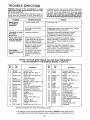
TROUBLE
SHOOTHNG
WARNING: Removal of the Arc Stabilizer or welder
cabinet tops for any reason must be done by a qualified service technician.
Be sure the branch circuit main disconnect switch or
circuit fuses are removed (or High Frequency Arc
Stabilizer and welder plug and cord removed from their
TROUBLE
receptacles) before removing the cabinet.. Placing the
"ON-OFF" switch on the attachment in the "OFF" position does not remove voltage from the power' leads
inside the High Frequency Arc Stabilizer-BE
SAFE
AND BE ALIVE, OPEN THE BRANCH CIRCUIT, OR UNPLUG BOTH THE WELDER AND THE ARC STABILIZER.
PROBABLE CAUSE
Spark gaps or
Arc Stabilizer
inoperative
REMEDY
"On-Off" switch "Off"
Turn switch "On"
Spark gaps eroded (gap
too wide).
Readjust spark gaps See "Maintenance"
for DANGER note and procedure.
Complaints of radio/
1_4or other
interference.
Improper instatlation_
Discontinue operation immediately Review
installation and grounding carefully, Refer
to "Installation" section of this manual
Arcing, odor, smoke,
noise or other signs
of welder damage°
Overheating from failure
to operate welder at reduced
output or duty cycle when
using AC GTAW process.
Discontinue operation immediately, Have
welder inspected or repaired by a qualified
service person Reduce welding current or
duty cycle
Damage to welder by high
frequency voltage from
............
_ ...imProper_installation,
Poor welding
performance with AC
welder,
section
Discontinue operation immediately Have
welder inspected or repaired by a qualified
, serv.ice #erson. Correct installation.
Arc Stabilizer and welder
connected to different
phases of a three phase
system..
Connect Arc Stabilizer and welder to the
same phase of the power system.
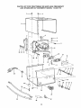
PARTS LIST FOR CRAFTSMAN
300 AMP HIGH FREQUENCY
ARC STABILIZER
ATTACHMENT
MODEL 113,201170
Key
No.
Part
No.
1
2
61443
STD601105
3
STD611005
4
5
6
7
8
9
10
11
12
13
!4
15
16
61451
STD541025
STD551025
17
18
19
STD541006
61115
61116
STD522505
61117
61446
60444
i61449
i61459
61447
61458
STD510607
Key
No.
Description
Cabinet, Top
*Screw, Pan Rec. Type "T"
10-32 x 1/2
*Screw, Pan Rec Type "AB"
N10 x 1/2
Support, Bracket
*Nut, Hex 1/4-20
*Washer; 17/64 x 47/64 x 1/16
=,Board, Asm
*Nut, 6-32
Block #5 Contact Mounting
Contabt, Selector Plug
*Screw, Hex 1/4-20 x 1/2
Block #6, Contact Mounting
Insulator
Washer, Spring
Stud
Washer; Fibre 266 x ..44
x 1/32
Insulator; Male
Washer; Fibre _656 x t
x 1/32
*Screw, Pan Hd_6-32 x 3/4
*Standard Hardware Item-May
Part
No°
20
21
61448
61460
22
23
24
25
STD551037
61452
61442
60359
26
27
28
29
61386
60361
61444
STD511110
30
31
32
33
34
35
36
37
-
803709
61450
STD551110
STD541110
61454
61455
61456
61453
61445
Description
Insulator, Female
Washer, Fibre 266 x 56
x 1/32
*Washer; .34 x .56 x 03
Switch
Cabinet, Bottom
Screw, Type "AB" No 10
x 1-1/4
Bumper, Recess
Relief, Strain
Cord with Plug
*Screw, Pan Rec. Type "T"
10-32 x 1
Connector, Wire
Lead Assembly
*Lockwasher No. 10
*Nut, Hex 10-32
Cable Assembly, Work
Cable Assembly, Electrode
Pfug Asernbly
Terminal Lug
Owners Manual (Not
illustrated)
be Purchased Locally
o Any attempt to repair this board assembly may create a HAZARD unless repair is done
by a qualified service technician., Repair service is available at your nearest Sears store
14
PARTS LIST FOR CRAFTSMAN
300 AMP HIGH FREQUENCY
ARC STABILIZER
ATTACHMENT
MODEL 113.201170
I
I
I
1
I
t
I
t
/Ii
33
32
1
31
/
1
9
10
28
27
!118
1
23
35
'37
36
15
20
21
22
5
300 AMP
HiGH FREQUENCY
ARC STABHLIZER
ATTACHMENT
SERVICE
MODEL NO=
113.201170
HOW TO ORDER
REPAIR PARTS
Now that you have purchased
your High Frequency
Arc
Stabilizer
Attachment,
should a need ever exist for repair
parts or services, simply contact any Sears Service Center
and most Sears, Roebuck
and Co. stores,
Be sure to
provide atl pertinent
factswhen
you call or visit,
The model number of your High Frequency
Arc Stabilizer
Attachment
will be found on a plate attached to the rear of
the cabineL
WHEN ORDERING
REPAIR
FOLLOWING
INFORMATION:
PARTS,
ALWAYS
GIVE
PART NUMBER
PART DESCRIPTION
MODEL NUMBER
113.201170
NAME OF ITEM
HIGH FREQUENCY
ARC STABILIZER
ATTACHMENT
THE
A!l parts listed may be ordered
from any Sears Service
Center' and rnost Sears stores. If the parts you need are not
stocked
locally,
your
order
will
be electronically
transmitted
to a Sears Repair Parts Distribution
Center fo.r
handling,
Sold by SEARS,
Part No 61445
ROEBUCK
AND
CO.,
Form No. SP4644
Chicago,
IL° 60684
U.S.A.
Printed in USA
4/83