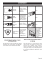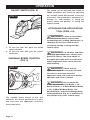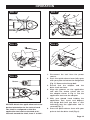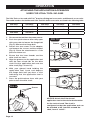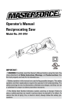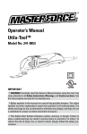
1
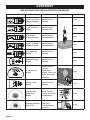
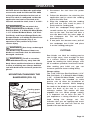
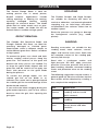
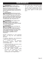
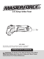
2.5 Amp Utila-Tool
241-0854
For questions / comments, technical assistance or repair parts –
Please Call Toll Free: 1-866-917-4374. (M-F 8am – 6pm EST)
OPERATOR’S MANUAL
CAUTION: To Reduce The Risk Of Injury, User Must
Read And Understand Operator’s Manual. Save These
Instructions For Future Reference.
Page 1
TABLE OF CONTENTS
Safety Symbols. . . . . . . . . . . . . . . . . . . . . . . . . . . . . . . . . . . . . . . . . . . . . . . . . . . . . . . . . . Page 2
Safety Instructions. . . . . . . . . . . . . . . . . . . . . . . . . . . . . . . . . . . . . . . . . . . . . . . . . . . . . . . Page 3
Overview / Specifications . . . . . . . . . . . . . . . . . . . . . . . . . . . . . . . . . . . . . . . . . . . . . . . . . Page 7
Assembly . . . . . . . . . . . . . . . . . . . . . . . . . . . . . . . . . . . . . . . . . . . . . . . . . . . . . . . . . . . . . . Page 8
Operation . . . . . . . . . . . . . . . . . . . . . . . . . . . . . . . . . . . . . . . . . . . . . . . . . . . . . . . . . . . . . Page 11
Maintenance. . . . . . . . . . . . . . . . . . . . . . . . . . . . . . . . . . . . . . . . . . . . . . . . . . . . . . . . . . . Page 16
Troubleshooting. . . . . . . . . . . . . . . . . . . . . . . . . . . . . . . . . . . . . . . . . . . . . . . . . . . . . . . . Page 17
Warranty. . . . . . . . . . . . . . . . . . . . . . . . . . . . . . . . . . . . . . . . . . . . . . . . . . . . . . . . . . . . . . Page 22
SAFETY SYMBOLS
Some of these following symbols may be used on this tool. Please study them and learn their
meaning. Proper interpretation of these symbols will allow you to operate the tool better and
safer.
Symbol
Name
Designation / Explanation
V
Volts
Voltage
A
Amperes
Current
Hz
Hertz
Frequency (cycles per second)
W
Watts
Power
∿
Alternating current
Type of current
�
Direct current
Type of characteristic of current
no
No-load speed
Rotational speed at no load
lbs
Pounds
Weight
Class II construction
Double insulated construction
Per minute
Revolutions, strokes, surface speed
orbits, etc., per minute
.../min
Wear safety goggles
WARNING: The operation of any
power tool can result in foreign objects
being thrown into your eyes, which can
result in severe eye damage. Before
beginning power tool operation, always
wear safety goggles or safety glasses
with side shields and a full-face shield
when needed. We recommend a Wide
Vision Safety Mask for use over eyeglasses or standard safety glasses with
side shields. Always use eye protection
which is marked to comply with
ANSI Z87.1.
WARNING: To ensure safety and reliability, all repairs should be performed by a
qualified service technician.
Page 2
SAFETY INSTRUCTIONS
The purpose of safety symbols is to attract your attention to possible dangers. The
safety symbols and the explanations with them deserve your careful attention and
understanding. The symbol warnings do not, by themselves, eliminate any danger. The
instructions and warnings they give are no substitutes for proper accident prevention
measures.
WARNING: Be sure to read and understand all safety instructions in this manual,
including all safety alert symbols such as “DANGER,” ”WARNING,” and “CAUTION”
before using this tool. Failure to following all instructions listed below may result in
electric shock, fire, and/or serious personal injury.
SYMBOL MEANING
SAFETY ALERT SYMBOL: Indicates DANGER, WARNING, OR CAUTION.
May be used in conjunction with other symbols or pictographs.
DANGER: Indicates an imminently hazardous situation, which, if not avoided,
will result in death or serious injury.
WARNING: Indicates a potentially hazardous situation, which, if not avoided,
could result in death or serious injury.
CAUTION: Indicates a potentially hazardous situation, which, if not avoided,
could result in minor or moderate injury.
NOTICE: (Without Safety Alert Symbol) Indicates a situation that may result in property
damage.
SAVE THESE INSTRUCTIONS!
Page 3
SAFETY INSTRUCTIONS
KNOW THE TOOL
WARNING: To reduce the risk of
injury, the user must read the operator’s
manual.
WARNING: Read all safety
warnings and instructions! Failure to
follow the warnings and instructions may
result in electric shock, fire and/or
serious injury. Save all warnings and
instructions for future reference.
The term “power tool” in the warnings
refers to your AC-powered (corded) power
tool or battery-powered (cordless) power
tool.
WARNING: Risk of fire and
electric shock. Dry location use only. Do
not expose to rain. Risk of injury.
WORK AREA SAFETY
1. Keep work area clean and well lit.
Cluttered or dark areas invite accidents.
2. Do not operate power tools in
explosive atmospheres, such as in the
presence of flammable liquids, gases
or dust. Power tools create sparks which
may ignite the dust or fumes.
3. Keep children and bystanders away
while operating a power tool. Distractions
can cause you to lose control.
ELECTRICAL SAFETY
1. The plug on the power tool must match
the outlet. Never modify the plug in any
way. Do not use any adapter plugs
with earthed (grounded) power tools.
Unmodified
plugs
and
matching
outlets will reduce risk of electric shock.
2. Avoid body contact with earthed or
grounded surfaces such as pipes, radiators,
ranges and refrigerators. There is an
increased risk of electric shock if your
body is earthed or grounded.
. Do not expose power tools to rain or
3
wet conditions. Water entering a power tool
will increase the risk of electric shock.
4. Do not abuse the cord. Never use the
cord for carrying, pulling or unplugging the
power tool. Keep the cord away from heat,
oil, sharp edges or moving parts. Damaged
or entangled cords increase the risk of
electric shock.
5. When operating a power tool outdoors,
use an extension cord suitable for outdoor
use. Use of a cord suitable for outdoor use
reduces the risk of electric shock.
6. If operating a power tool in a damp
location is unavoidable, use a ground fault
circuit interrupter (GFCI) protected supply.
Use of a GFCI reduces the risk of electric
shock.
PERSONAL SAFETY
1. Stay alert, watch what you are doing
and use common sense when operating
a power tool. Do not use the tool while
tired or under the influence of drugs,
alcohol, or medication. A moment of
inattention while operating power tools may
result in serious personal injury.
2. Use personal protective equipment.
Always wear eye protection. Protective
equipment such as a dust mask, non-skid
safety shoes, hard hat, or hearing
protection, used for appropriate conditions,
will reduce personal injuries.
3. Prevent unintentional starting. Ensure
that the switch is in the off-position
before connecting to power source and /
or battery pack, picking up or carrying the
tool. Carrying power tools with your finger
on the switch or energizing power tools that
have the switch on invites accidents.
4. Remove any adjusting key or wrench
before turning the power tool on. A wrench
or a key left attached to a rotating part of
the power tool may result in personal injury.
Page 4
SAFETY INSTRUCTIONS
5. Do not overreach. Keep proper footing
and balance at all times. This enables
better control of the power tool in
unexpected situations.
6. Dress properly. Do not wear loose
clothing or jewelry. Keep your hair,
clothing and gloves away from moving
parts. Loose clothes, jewelry or long hair
can be caught in moving parts.
7. If devices are provided for the
connection of dust extraction and collection
facilities, ensure that these are connected
and properly used. Use of these devices
can reduce dust-related hazards.
USE AND CARE OF
THE POWER TOOLS
1. Do not force the power tool. Use the
correct power tool for your application.
The correct power tool will do the job
better and more safely at the rate for
which it was designed.
2. Do not use the power tool if the switch
does not turn it on and off. Any power tool
that cannot be controlled with the switch is
dangerous and must be repaired.
3. Disconnect the plug from the power
source and/or the battery pack from
the power tool before making any
adjustments, changing accessories, or
storing power tools. Such preventive
safety measures reduce the risk of starting
the power tool accidentally.
4. Store idle power tools out of the reach of
children and do not allow persons unfamiliar
with the power tool or these instructions
to operate the power tool. Power tools are
dangerous in the hands of untrained users.
5. Maintain power tools. Check for
misalignment or binding of moving parts,
breakage of parts and any other condition
that may affect the power tool’s operation.
If damaged, have the power tool repaired
before use. Many accidents are caused by
poorly maintained power tools.
Page 5
6. Keep cutting tools sharp and clean.
Properly maintained cutting tools with sharp
cutting edges are less likely to bind and
are easier to control.
7. Use the power tool, accessories, tool
bits etc., in accordance with these
instructions, taking into account the
working conditions and the work to be
performed. Use of the power tool for
operations different from those intended
could result in a hazardous situation.
SERVICE
1. Have your power tool serviced by a
qualified repair person using only identical
replacement parts. This will ensure that the
safety of the power tool is maintained.
SPECIFIC SAFETY RULES FOR
UTILA-TOOL
1. Hold power tools by the insulated
gripping surfaces when performing an
operation where the cutting tool may
contact hidden wiring. Contact with a
“live” wire will make exposed metal parts of
the tool live and shock the operator.
2. Never use your Utila-tool to perform
sanding or separating operations in wet
conditions.
3. Always wear eye protection.
4. Always wear ear protection during
extended periods of operation.
5. Always wear a dust mask if the
operation is dusty.
6. Wear
protective
gloves
when
changing
application
accessories.
Application accessories become hot after
prolonged usage.
7. Always inspect for and remove all
nails, screws, staples, etc., before sanding.
8. Always check walls and ceilings to
avoid hidden power cables and pipes. A
metal detector (available separately) is very
helpful for this purpose.
SAFETY INSTRUCTIONS
9. Whenever possible, use clamping
devices or other suitable means to secure
the workpiece to a firm surface.
10. When working with the Utila-tool,
always hold it firmly with both hands and
provide for a secure stance. The power tool
is guided more securely with both hands.
11. Keep your workplace clean. Blends of
materials are particularly dangerous. Dust
from light alloys can burn or explode.
12. Avoid unintentionally switching on the
tool. Ensure that the on/off switch is in
the OFF position before connecting to the
power source. Do not carry the power tool
with your finger on the on/off switch or
connect to the power source that have the
switch on.
13. Do not scrape wet or dampened
materials (e.g., wallpaper) or on moist
surfaces. Penetration of water into the tool
increases the risk of an electric shock.
14. Keep your hands away from the cutting
area. Do not reach under the material
being cut.
15. When operating a power tool outside,
use an outdoor extension cord marked
“W-A” or “W”. These cords are rated for
outdoor use and reduce the risk of electric
shock. The following table shows the correct
size to use, depending on cord length and
nameplate amperage rating of the tool.
When in doubt, use the next heavier gauge.
Always use UL and CSA listed extension
cords.
Recommended sizes of extension cords:
Tool’s Ampere Rating
Total length of cord in feet
Cord size in A. W. G. (minimum)
Volts
25’
50’
100’
150’
0-6
18
16
16
14
6-10
18
16
14
12
16
16
14
12
14
12
10-12
12-16
120 V~
Not Recommended
Page 6
OVERVIEW
FIG. 1
Quick-Release Lever
On/Off Switch
Variable-Speed Dial
Vent
Shaft
Attachment plate
Flange Bolt
SPECIFICATIONS
Rated voltage
120V 60 Hz
Rated power
2.5A
Oscillating rating
11,000-20,000/min (No load)
Oscillating range
±1.4°
Weight
Page 7
3 lbs. 7 oz.
ASSEMBLY
WARNING: If any part is broken
or missing, DO NOT attempt to plug in the
power cord or operate the tool until the
broken or missing part is replaced. Failure
to do so could result in possible serious
injury.
WARNING: Do not attempt to
modify this tool or create accessories not
recommended for use with this tool. Any
such alteration or modification is misuse
and could result in a hazardous condition
leading to possible serious injury.
UNPACKING
1.This product has been shipped
completely assembled.
2. Carefully remove the tool and any
accessories from the box. Make sure
that all items listed in the packing list
are included.
3. Inspect the tool carefully to make sure
no breakage or damage occurred
during shipping.
4. Do not discard the packing material
until you have carefully inspected and
satisfactorily operated the tool.
WARNING: Your tool should never
be connected to the power source when
you are assembling parts, making
adjustments, installing or removing
application tool, cleaning, or when it is not
in use. Disconnecting the tool will prevent
accidental starting, which could cause
serious personal injury.
CONTENTS
2.5A Utila-Tool . . . . . . . . . . . . . . . . . . . 1 pc
1-3/8” Precision End-Cut Blade . . . . . 1 pc
1-1/4” End-Cut Blade. . . . . . . . . . . . . . 1 pc
2” 3-Sided Bi-Metal Blade. . . . . . . . . . 1 pc
1-1/4” 3-Sided Bi-Metal Blade. . . . . . . 1 pc
3/8” End-Cut Blade . . . . . . . . . . . . . . . 1 pc
Curved-Plunge Blade. . . . . . . . . . . . . . 1 pc
4” Semicircle Blade . . . . . . . . . . . . . . . 1 pc
2-9/16” Saw Blade. . . . . . . . . . . . . . . . 1 pc
Carbide Grit Semicircle Blade . . . . . . 1 pc
Triangle Carbide Grit Rasp. . . . . . . . . . 1 pc
Flexible Scraper. . . . . . . . . . . . . . . . . . 1 pc
Rigid Scraper. . . . . . . . . . . . . . . . . . . . 1 pc
Caulk Removal Knife . . . . . . . . . . . . . . 1 pc
Sanding Pad. . . . . . . . . . . . . . . . . . . . . 1 pc
Sanding Paper . . . . . . . . . . . . . . . . . . 41 pcs
Operator’s manual
Page 8
ASSEMBLY
SELECTING THE APPLICATION ACCESSORY
Page 9
NAME
MATERIALS
APPLICATION
QUANTITY
1-3/8” Precision
End-Cut Blade
Wood, Plastic,
Drywall
1-1/4” End-Cut
Blade
Wood, Plastic,
Drywall, Nail
1 pc
2” 3-Sided
Bi-Metal Blade
Wood, Plastic,
Drywall, Metal
1 pc
1-1/4” 3-Sided
Bi-Metal Blade
Wood, Plastic,
Drywall, Metal
1 pc
3/8” End-Cut
Blade
Wood, Plastic,
Drywall
1 pc
Curved Plunge
Blade
Wood, Plastic,
Drywall
1 pc
4” Semicircle
Blade
Wood, Plastic,
Drywall,
Nonferrous
Metals, Thin steel
Metal and other
materials
1 pc
2-9/16“ Saw
Blade
Wood, Plastic,
Drywall
1 pc
Carbide Grit
Semicircle
Blade
Grout, Plaster,
Porous Concrete
and Masonry
1 pc
Triangle Carbide
Grit Rasp
Hardened
adhesives,
Thinset, Wood,
Masonry
1 pc
1 pc
ASSEMBLY
NAME
MATERIALS
Flexible
Scraper
Plastic, Carpet,
Caulking, Paint &
Varnish,
Adhesives
1 pc
Rigid
Scraper
Paint & Varnish,
Bonded Carpet,
Soft Adhesives,
Vinyl Flooring,
Wood and other
floor coverings
1 pc
Caulk
Removal
Knife
Plastic, Silicon
Sealant, Caulking
1 pc
Bare or Painted
Wood, Plaster,
and other
surfaces,
depending on
sandpaper grit
1 pc sanding
pad+ 41 pcs
sandpaper
(60 grits/120
grits/240
grits/320 grits
- 8 pcs of
each, 80 grits
– 9 pcs)
Sanding Pad
and
Sandpaper
APPLICATION
QUANTITY
COMPATIBILITY WITH OTHER
ACCESSORIES
MULTI-FUNCTION DRIVE SHAFT
SYSTEM
The Utila-Tool can be used with Fein® brand
oscillating tool accessories and Menards
accessories used for Utila-tool 241-0853.
The Utila-Tool has a multi-function drive
shaft system that allows the tool to be
used for dry sanding small surfaces,
corners and edges, for scraping, and for
sawing thin steel sheet, wood and plastic
by attaching different application tool
supplied.
Page 10
OPERATION
ON/OFF SWITCH (FIG. 2)
FIG. 2
The speed can be adjusted from 11000 to
20000 oscillations per minute by adjusting
the variable speed dial located at the rear
of the tool. The speed dial is numbered “1”
through “6”, with position “1” being the
lowest speed and position “6” being the
highest speed.
ATTACHING THE APPLICATION
TOOL (FIGS. 4-8)
1. To turn the tool ON, push the on/off
switch forward.
2. To turn the tool OFF, pull the switch
backward.
VARIABLE-SPEED CONTROL
(FIG. 3)
FIG. 3
WARNING: Failure to disconnect
the tool from the power source when
assembling parts, making adjustments, or
changing accessories could result in
accidental starting, causing possible
serious injury.
WARNING: For all work, and when
changing application tools, always wear
protective gloves. The sharp edges of
the application tools will cause personal
injury. Application tools can be very hot
while working.
1
2
WARNING: Check that the
application tools are correctly attached.
Incorrect or insecurely fastened
application tools can come loose during
operation and cause a hazard.
The variable speed feature of this tool
enhances the overall performance of your
tool and saves the application accessory
from undue wear.
Page 11
WARNING: Do not attach the
1-3/8” Precision End-Cut Blade, 1-1/4”
End-Cut Blade, 2” 3-Sided Bi-Metal Blade,
1-1/4” 3-Sided Bi-Metal Blade, 3/8”
End-Cut Blade, and Curved Plunge Blade
facing backwards (Fig. 4), as operation in
this position may cause serious injury.
OPERATION
FIG. 4
FIG. 7
FIG. 5
FIG. 8
FIG. 6
Groove
Rib
NOTICE: Attach the application tool at the
desired orientation for the task at hand.
The shaft is configured so that the
application tool can be attached at 30°
intervals around the shaft, from 0° to 330°.
1. Disconnect the tool from the power
source.
2. Push the quick-release lever fully open
with your palm to loosen the flange bolt
(Fig. 5). Remove the flange bolt.
3.Ensure that the adapter and the
drive shaft are clean.
4. Align the grooves on the application
tool with the twelve raised ribs on
the adapter shown in Fig. 6. Put the
application tool onto the adapter.
5. With your gloved hand holding the
application tool, insert and depress
the flange bolt until you hear a click
indicating that the application tool is
secured (Fig. 7).
6. Press the quick-release lever with your
palm to lock the drive shaft (Fig. 8).
Page 12
OPERATION
ATTACHING THE APPLICATION ACCESSORY
USED FOR UTILA-TOOL 241-0853
The Utila-Tool can be used with Fein® brand oscillating tool accessories and Menards accessories.
The model numbers for the Menards Utila-Tool 241-0853 accessories are listed in the following table.
236-0851
236-0852
236-0853
236-0854
236-0855
236-0856
236-0857
236-0858
236-0859
236-0863
236-0864
236-0865
236-0866
236-0867
236-0868
236-0869
236-0870
1. Disconnect the tool from the power source.
2. Push the quick-release lever fully open
with your palm to loosen the flange bolt
(Fig. 5). Remove the flange bolt.
3. Loosen the two screws in the adapter,
and remove the screws and the adapter
(Fig. 9). Place the attachment in a safe
place for future use.
4. Ensure that the inner threads and the
drive shaft are clean.
5. Align the grooves on the application tool
with the four raised ribs on the drive
shaft. Put the application tool onto the
drive shaft (Figs. 10 and 11).
6. With your gloved hand holding the
application tool, insert and depress
the flange bolt until you hear a click
indicating that the application tool is
secured.
7. Press the quick-release lever with your
palm to lock the drive shaft.
FIG. 9
FIG. 10
Groove
Rib
FIG. 11
Screws
NOTICE: Attach the Fein® brand
application tool at the desired orientation
for the task at hand. The shaft is
configured so that the application tool can
be attached at 45° intervals around the
shaft, from 0° to 315°.
Page 13
OPERATION
NOTICE: Attach the Menards application
accessories used for Utila-tool 241-0853
at the desired orientation for the task at
hand. The shaft is configured so that the
application tool can be attached at 30°
intervals around the shaft, from 0° to 330°.
WARNING: Do not attach the
1-3/8” Precision End-Cut Blade, 1-1/4”
End-Cut Blade, 2” 3-Sided Bi-Metal Blade,
1-1/4” 3-Sided Bi-Metal Blade, 3/8” EndCut Blade, and Curved Plunge Blade, the
Scraper Blades or Carbide Grit Semicircle
Blade facing backwards (Fig. 4), as
operation in this position may cause
serious injury.
WARNING: Use sharp, undamaged
saw blades only. Deformed, blunt saw
blades or saw blades that are otherwise
damaged can break.
WARNING: For all accessories,
work with the accessory away from the
body. Never position hand near or directly
in front of working area. Always hold the
tool with both hands and wear protective
gloves.
MOUNTING/CHANGING THE
SANDPAPER (FIG. 12)
FIG. 12
Sanding paper
Sanding pad
1. Disconnect the tool from the power
source.
2. Follow the directions for attaching the
application tool to attach the sanding
pad to the Utila-Tool.
3. Align the sandpaper with the sanding
pad and use your hand to press it
firmly onto the sanding pad.
4. Press the sandpaper firmly against a
smooth surface for a short period, then
turn on the tool. The burr will form a
non-slip bond with the outer edge of
the sandpaper felt. This will avoid
premature wear.
5. If one point has become worn, pull off
the sandpaper, turn it 120° and place
it on the sanding pad again.
CUTTING
Saw blades are ideal for making precise
cuts in tight areas, close to edges or flush
to a surface. Select a medium to high
speed for making the initial plunge; start
off at medium speed for increased control.
After making your initial cut, you can
increase speed for faster cutting ability.
Plunge cutting
The 1-3/8” Precision End-Cut Blade, 1-1/4”
End-Cut Blade, 2” 3-Sided Bi-Metal Blade,
1-1/4” 3-Sided Bi-Metal Blade, and 3/8”
End-Cut Blade, are intended to make
precise cuts to allow for installation of
flooring or wall material. While keeping
the teeth of the blade in the work surface,
move the back of the tool in a slow
sideways motion. This motion will help
expedite the cut. When plunge cutting,
it is important not to force the tool. If
you experience a strong vibration in your
hand during the plunge cut, this
indicates that you are applying too much
pressure. Back the tool out and let the
speed of the tool do the work.
Page 14
OPERATION
The Curved Plunge Blade is ideal for
making precise cuts in wood, plaster,
drywall material. Applications include
cutting openings in flooring for venting,
repairing
damaged
flooring,
cutting
openings for electrical boxes. The blade
works best on softer woods such as pine.
For harder woods, the blade life will be
limited. Select a medium to high speed.
GROUT REMOVAL
The Carbide Grit Semicircle Blade and
Triangle Carbide Grit Rasp, are ideal for
removing damaged or cracked grout.
Grout blades come in different shapes to
tackle different grout lines. Select a medium
to high speed.
To remove the grout, use a back and forth
motion, making several passes along the
grout line. The hardness of the grout will
dictate how many passes are needed. Try
to keep the grout blade aligned with the
grout line and be careful not to apply too
much side pressure on the grout blade
during the process.
To control the plunge depth, use the
carbide grit line on the blade as an
indicator. Be careful not to plunge beyond
the carbide grit line to avoid damage to the
backer board material.
If you notice the blade clogging during the
grout removal process, you can use a brass
brush to clean the grit, thus exposing the
grit again.
Page 15
SCRAPING
The Flexible Scraper and Rigid Scraper
are suitable for removing old coats of
varnish or adhesives, and removing bonded
carpeting, e.g., on stairs/steps and others
small/medium size surfaces. Select low to
medium speed.
Excessive pressure can gouge or damage
the background surfaces (e.g., wood,
plaster).
SANDING
Sanding accessories are suitable for dry
sanding wood, metal surfaces, corners,
edges and hard to reach areas. Work with
the complete surface of the sanding pad,
not only with the tip.
Sand with a continuous motion and
light pressure. DO NOT apply excessive
pressure. Excessive pressure will result in
poor handling, vibration, unwanted sanding
marks and premature wear on the sanding
sheet.
The following suggestions may be used as a
general guide for abrasive selection, but the
best results will be obtained by sanding a
test sample of the workpiece first.
Grit
Application
Coarse
For rough wood or metal
sanding, and rust or old
finish removal.
Medium
For general wood or metal
sanding.
Fine
For final finishing of wood,
metal, plaster and other
surfaces.
MAINTENANCE
WARNING:
To avoid serious
personal injury, always disconnect the
plug from the power source when
cleaning or performing any maintenance.
Contact a qualified service technician for
ALL repairs.
4. Use a soft, clean, damp cloth to wipe
the tool housing. A mild detergent
can be used but nothing like alcohol,
petrol or other cleaning agent. Never
use caustic agents to clean plastic
parts.
WARNING: Avoid using solvents
when cleaning plastic parts. Most plastics
are susceptible to damage from various
types of commercial solvents and may be
damaged by their use. Use a clean cloth
to remove dirt, dust, oil, grease, etc.
WARNING: If the supply cord is
damaged, it must be replaced by a
specially prepared cord available through
the service organization.
WARNING: When servicing, use
only identical replacement parts. Use of
any other parts may create a hazard or
cause product damage. To ensure safety
and reliability, all repairs should be
performed by a qualified service
technician.
Periodic maintenance of your Utila-Tool
allows for long life and trouble-free
operation.
A cleaning, lubrication and maintenance
schedule should be maintained.
As a common-sense and preventive
maintenance
practice,
follow
these
recommended steps:
1. Inspect the tool and accessories; check
them for wear or damage.
2.Keep the ventilation slots clean to
prevent overheating of the motor.
3.
The tool maybe cleaned most
effectively with compressed dry air.
Always wear safety goggles when
cleaning tools with compressed air.
Page 16
TROUBLESHOOTING
PROBLEM
CAUSE
SOLUTION
The tool will not start.
The tool is not plugged
into a power source.
Plug the tool into a power source.
The circuit breaker is
tripped.
Reset the circuit breaker. (If the
product repeatedly causes the
circuit breaker to trip, discontinue
use immediately and have the
tool serviced at an authorized
service center.
The cord is damaged.
Have the cord or switch replaced
at an authorized service center.
Too much pressure is
being exerted on the tool.
Let the tool run under no load to
cool down.
Make sure the cooling
vents are free from dust
and obstacles.
Clean and clear the vents. Do not
cover vents with your hand during
operation.
The motor is overheating.
Page 17
NOTES
Page 18
NOTES
Page 19
NOTES
Page 20
NOTES
Page 21
2.5A UTILA-TOOL
WARRANTY
90-DAY MONEY BACK GUARANTEE:
This MASTERFORCE® brand power tool carries our 90-DAY Money Back
Guarantee. If you are not completely satisfied with your MASTERFORCE® brand
power tool for any reason within ninety (90) days from the date of purchase, return
the tool with your original receipt to any MENARDS® retail store, and we will provide
you a refund – no questions asked.
3-YEAR LIMITED WARRANTY:
This MASTERFORCE® brand power tool carries our famous No Hassle 3-Year
Limited Warranty to the original purchaser.
If, during normal use, this
MASTERFORCE® power tool breaks or fails due to a defect in material or
workmanship within three (3) years from the date of original purchase, simply bring
this tool with the original sales receipt back to your nearest MENARDS® retail store.
At its discretion, MASTERFORCE® agrees to have the tool or any defective part(s)
repaired or replaced with the same or similar MASTERFORCE® product or part
free of charge, within the stated warranty period, when returned by the original
purchaser with original sales receipt. Not withstanding the foregoing, this limited
warranty does not cover any damage that has resulted from abuse or misuse of
the Merchandise. This warranty: (1) excludes expendable parts including but not
limited to blades, brushes, belts, bits, light bulbs, and/or batteries; (2) shall be void
if this tool is used for commercial and/or rental purposes; and (3) does not cover any
losses, injuries to persons/property or costs. This warranty does give you specific
legal rights and you may have other rights, which vary from state to state. Be
careful, tools are dangerous if improperly used or maintained. Seller’s employees
are not qualified to advise you on the use of this Merchandise. Any oral
representation(s) made will not be binding on seller or its employees. The rights
under this limited warranty are to the original purchaser of the Merchandise and may
not be transferred to any subsequent owner. This limited warranty is in lieu of all
warranties, expressed or implied including warranties or merchantability and fitness
for a particular purpose. Seller shall not be liable for any special, incidental, or
consequential damages. The sole exclusive remedy against the seller will be for the
replacement of any defects as provided herein, as long as the seller is willing or
able to replace this product or is willing to refund the purchase price as provided
above. For insurance purposes, seller is not allowed to demonstrate any of these
power tools for you.
For questions / comments, technical assistance or repair parts – Please Call Toll
Free at: 1-866-917-4374. (M-F 8am – 6pm EST)
SAVE YOUR RECEIPTS
THIS WARRANTY IS VOID WITHOUT THEM
Page 22
© 2012 Menard, Inc., Eau Claire, WI 54703
Page 24
02/2012