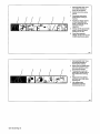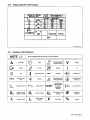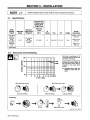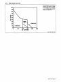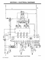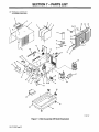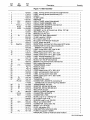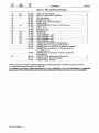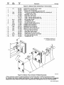
1
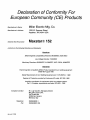
DM172 200
May
1996
Elf. wlSerial Number KG117815
Miller.
Processes
TIG
The Power ofBlue.
(GTAW) Welding
Stick
With
(SMAW) Welding
Optional Equipment:
Pulsed TIG
(GTAW-P) Welding
Description
Arc
Welding
Power Source
Maxstarfi 152
0
1911
Visit
our
website at
wwwMIIlerWelds~com
OWNERS
MANUAL
From Miller to You
Thank you and
you
can
congratulations on choosing Miller. Now
get the job done and get it done right. We know
you dont
Thats
have time to do it any other way.
why
when Niels Miller first started
building arc
welders in 1929, he made sure his products offered
long-lasting value and superior quality. Like you, his
customers couldnt afford anything less. Miller products
had to be more than the best they could be. They had to
be the best you could buy.
people that build and sell Miller products continue the
tradition. Theyre just as committed to providing equipment and service
that meets the high standards of quality and value established in 1929.
Today,
the
This Owners
Miller
help
Manual is
products.
you protect
designed
to
help
you get the most out of your
Please take time to read the
yourself against potential
Safety precautions. They
hazards
made installation and
on
will
the worksite. Weve
operation quick
and easy.
With Miller you can count on years of reliable
service with proper maintenance. And if for
jMIIllhIIIPr
REGISTERED
QUALITY SYSTEM
some reason
the unit needs
______________
repair,
theres
a
section that will
Troubleshooting
help you
what
the
is.
The
out
figure
problem
parts list
will then help you to decide which exact part
you may need to fix the problem. Warranty and
service information for your particular model
are also provided.
Miller is the first welding
equipment manufacturer in
the U.S.A. to be registered
to the iSO 9001 Quality
System Standard.
~1~flft~3ft1ll1~!
L~W
Working as hard as you do
every power source from
Miller is backed by the most
hassle-tree warranty in the
business.
Miller Electric manufactures
of welders and
welding
For information
products,
to
on
a
full line
related
other
equipment.
quality Miller
contact your local Miller
receive the latest full line
individual
catalog
distributor
catalog
or
sheets. To locate your nearest
distributor call 1-800-4-A-Miller.
~I7A Miller
w
The Thwer ofBlue.
Call
1 -800-4-A-MILLER
for your local
Miller distributor.
TABLE OF CONTENTS
SECTION 1
gives
READ BEFORE USING
1-5.
EMF Information
1-3.
Your distributor
-
1-4.
1-2.
you
SAFETY PRECAUTIONS
Symbol Usage
Arc Welding Hazards
Additional Symbols For Installation, Operation, And Maintenance
Principal Safety Standards
1-1.
1
1
1
3
3
4
Service
You
SECTION 1
always get the fast,
1-1.
reliable response you
need. Most replacement
1-2.
CONSIGNES DE SECURITE
Signification des symboles
Dangers relatits au soudage a Iarc
Dangers supplementaires en relation
be in your
hands in 24 hours.
1-3.
Support
1-4.
Principales
normes
1-5.
Information
sur
parts
can
Need fast
answers to
the
Contact your distributor.
The expertise of the
distributor and Miller is
SECTION 2
2-1.
2-2.
help you, every
the way.
there to
2-3.
les
5
avec
Iinstallation, le fonctionnement
7
de sØcuritØ
champs Ølectromagnetiques
DEFINITIONS
Manufacturers
Warning
Label Definitions For CE Products
And Definitions
SECTION 3INSTALLATION
3-1.
And
Overheating
parts information for your
3-5.
unit. To obtain
Technical
3-6.
contact your local
3-7.
Electrical Service Guide
Miller offers
a
Manual which
more
Technical
3-3.
provides
detailed seivice and
Manual,
a
distributor. Your distributor
can also supply you with
Welding
Process Manuals
suchasSMAW, GTAW,
GMAW, and GMAW-P.
For practical information
SECTION 4OPERATION
4-1.
Front Panel Controls
4-2.
Lift-Arc TIG Procedure
SECTION 5
on
welding, process applica
tions, and Miller products,
visit
3-4.
following terms are
interchangeably
throughout this manual:
used
TIG
GTAW
Stick
SMAW
=
=
MAINTENANCE & TROUBLESHOOTING
12
13
14
15
15
15
16
16
17
17
Routine Maintenance
17
Replacing Power Cord In Non-CE Models
Measuring Input Capacitor Voltage
Troubleshooting
18
5-3.
18
19
SECTION 6
ELECTRICAL DIAGRAMS
20
SECTION 7
PARTS LIST
22
WARRANTY
The
11
12
5-2.
5-4.
www.MHlerWelds.com
9
11
5-1.
website at
our
8
12
Specifications
Duty Cycle
Volt-Ampere Curves
Selecting A Location And Connecting Input Power
Weld Output Receptacles And Selecting Cable Sizes
Remote 14 Receptacle Information
3-2.
8
9
Label For CE Products
Rating
Symbols
5
5
et Ia maintenance
tough welding questions?
step of
LIRE AVANT UTILISATION
Declaration of
Conformity For
European Community (CE) Products
Miller Electric
Manufacturers
Name:
Manufacturers
Address:
Declares that the
conforms to the
Co.
Spencer Street
Appleton, WI 54914 USA
1635 W.
IVlaxstarfi 1 52
product:
following
Mfg.
Directives and Standards:
Directives
Electromagnetic compatibility Directives: 89/336/EEC,
Low
Voltage
92/31/EEC
Directive: 73/23/EEC
Machinery Directives: 89/392/EEC, 91/368/EEC,
93/C 133/04, 93/68/EEC
Standards
Electromagnetic compatibility (EMC)
Product standard for
EN50199:
Safety Requirements
Degrees
for Arc
of Protection
August
Welding Equipment part
provided by
Enclosures
Insulation coordination for
Part 1:
European Contact:
Mr.
Luigi Vacchini, Managing
Europe S.P.A.
Via Privata Iseo
20098 San Giuliano
Milanese, Italy
Fax:
dec_conl 10/95
welding equipment:
1: EN 60974-1: 1989
(IP code):
lEG 529:1989
equipment within low-voltage systems:
Principles, requirements and tests: IEC 664-1: 1992
MILLER
Telephone:
arc
1995
39(02)98290-1
39(02)98281-552
Director
SECTION 1
-
SAFETY PRECAUTIONS
READ BEFORE USING
-
som
1-1
Symbol Usage ~
Marks
This group of symbols means Warning! Watch Out! possible
ELECTRIC SHOCK, MOVING PARTS, and HOT PARTS hazards.
Consult symbols and related instructions below for necessary
actions to avoid the hazards.
special safety message.
a
~ Means Note;
not
related.
safety
Arc Welding Hazards
1-2.
A
.:....:~.:.H: :
Watch Out
There are possible
Means Warning
hazards with this procedure! The possible hazards are
shown in the adjoining symbols.
AA
A
shown below
symbols
The
to call attention to and
are used throughout this manual
Identify possible hazards. When you
symbol, watch out, and follow the related instructions
safety information given below is
only a summary of the more complete safety Information
found in the Safety Standards listed in Section 1-4. Read and
follow all Safety Standards.
see
the
to avoid the hazard. The
A Only qualified persons should install, operate, maintain, and
repair this unit.
A
_nd_5/97
During operation, keep everybody, especially children, away.
If earth
with
grounding
Use only well-maintained
Wear
a
Keep
all
Clamp
harness if
safety
panels
and
Do not touch live electrical
Wear
worktable
as near
clamp
single
weld
and
Do not use AC output in damp areas, if movement is confined,
there is a danger of falling.
Use AC
If AC
or
if
output
required,
use remote
output
control if
present
on
unit.
Disconnect
input power or stop engine before installing or
equipment. Lockout/tagout input power according
CFR 191 0.147 (see Safety Standards).
this
to OSHA 29
Properly install
Owners
ground
and
this
equipment according
to its
Manual and national, state, and local codes.
making input connections,
conductor first
attach
proper
grounding
double-check connections.
Frequently inspect input power cord for damage or bare wiring
replace cord immediately if damaged bare wiring can kill.
Turn off all
equipment
Do not
worn, damaged, undersized,
Do not
use
drape
cables
when not in
over
as
when not connected to
workpiece
to
prevent
object.
than
more
workpiece
practical.
one
electrode
or
work cable to any
FUMESANDGASEScanbehazardous
1~
=~-H
If
inside,
use.
your body.
or
Welding produces fumes
these fumes and gases
health.
head out of the fumes. Do not breathe the fumes.
ventilate the
welding fumes
If ventilation is poor,
Read
the
and gases. Breathing
be hazardous to your
can
Material
manufacturers
and/or
area
use
exhaust at the
arc
to
and gases.
use an
approved air-supplied respirator.
Safety
Data
Sheets
(MSDSs)
instructions for metals, consumables,
and
the
coatings,
cleaners, and degreasers.
Work in
Always verify the supply ground check and be sure that input
power cord ground wire is properly connected to ground terminal
in disconnect box or that cord plug is connected to a properly
grounded receptacle outlet.
When
good
the weld
Turn Off inverter, disconnect input power, and discharge input
capacitors according to instructions in Maintenance Section
before touching any parts.
remove
servicing
place.
SIGNIFICANT DC VOLTAGE exists after removal of
input power on inverters.
Keep your
output ONLY if required for the welding process.
is
in
metal-to-metal contact to
output terminal.
~
ground using dry insulating mats
prevent any physical contact with the
to
above floor level.
securely
body protection.
from work and
yourself
or covers big enough
work or ground.
working
parts.
dry, hole-free insulating gloves
Insulate
ground,
equipment. Repair or replace damaged
according to manual.
covers
work cable with
Do not connect
electrical parts can cause fatal
shocks or severe burns. The electrode and work
circuit is electrically live whenever the output is on.
The input power circuit and machine internal
circuits are also live when power is on. In semiautomatic or
automatic wire welding, the wire, wire reel, drive roll housing, and all
metal parts touching the welding wire are electrically live. Incorrectly
installed or improperly grounded equipment is a hazard.
required, ground it directly
clamp or work cable.
at once. Maintain unit
parts
contact with any metal
live
Touching
is
work
use
Do not touch electrode if you are in contact with the work,
another electrode from a different machine.
Insulate work
~
workpiece
do not
or
or
ELECTRIC SHOCKcan~kflL
of the
separate cable
a
poorly spliced cables.
a confined space only if it is well ventilated, or while
wearing an air-supplied respirator. Always have a trained watchperson nearby. Welding fumes and gases can displace air and
lower the oxygen level causing injury or death. Be sure the
breathing
air is safe.
Do not weld in locations
near
degreasing, cleaning,
operations. The heat and rays of the
form
highly
toxic and
Do not weld
irritating
arc can
or
spraying
react with vapors to
gases.
coated metals, such as galvanized, lead, or
cadmium plated steel, unless the coating is removed from the
weld area, the area is well ventilated, and if necessary, while
on
wearing an air-supplied respirator. The coatings and any metals
containing these elements can give oft toxic fumes if welded.
OM-172 200
Page
1
ARC RAYS
bum
can
~POFGAScannIurŁorkiU.
eyesandŁkIn~....
Shutoff
shielding gas supply when not in
Always ventilate confined spaces or
approved air-supplied respirator.
Arc rays from the welding process produce intense
visible and invisible (ultraviolet and infrared) rays
that can burn eyes and skin. Sparks fly off from the
weld.
use.
use
Wear a welding helmet fitted with a propershade of filterto protect
your face and eyes when welding or watching (see ANSI Z49.1
and Z87.1 listed in
Wear
Safety Standards).
approved safety glasses
bumL.~
HOT PARTSCaæ: causesivere
I
with side shields under your
helmet.
Do not touch hot
Use
Allow
protective screens or barriers to protect others from flash and
glare; warn others not to watch the arc.
parts bare handed.
cooling period before working
on
gun
or
torch.
Wear protective clothing made from durable, flame-resistant
material (leather and wool) and foot protection.
WELDING
can cause fire or
explosion
Welding
on closed containers, such as tanks,
drums, or pipes, can cause them to blow up. Sparks
can fly off from the welding arc. The flying sparks,
I
I
MACLDScanaffectpacemakers~
I
Pacemaker
~~
yourself
and others from
Do not weld where
flying sparks
flying sparks
can
NOISEcan
Noise from
strike flammable material.
that
aware
can cause
fire
Do not weld
on
welding
on
a
extinguisher nearby.
ceiling, floor, bulkhead,
closed containers such
Connect work cable to the work
unknown
Do not
prevent welding
paths
use
some
processes
or
equipment
can
Wear
approved
ear
protection
if noise level is
high.
CYLINDERS can explode if damaged~
partition
or
the hidden side.
as
tanks, drums,
they are properly prepared according
Safety Standards).
to
damage hearhig.~:.
fire
on a
unless
practical
spot
or
damage hearing.
Be alert that welding sparks and hot materials from welding can
easily go through small cracks and openings to adjacent areas.
Be
away.
and hot metal.
Remove all flammables within 35 ft (10.7 m) of the welding arc. If
this is not possible, tightly cover them with approved covers.
Watch for fire, and keep
keep
going near arc welding, gouging,
welding operations.
____________
hot workpiece, and hot equipment can cause fires
and burns. Accidental contact of electrode to metal objects can
cause sparks, explosion, overheating, or fire. Check and be sure the
area is safe before doing any welding.
Protect
wearers
Wearers should consult their doctor before
and
as
welding area as
traveling long, possibly
electric shock and fire hazards.
welder to thaw frozen
Shielding
gas cylinders contain gas under high
pressure. If damaged, a cylinder can explode.
Since gas cylinders are normally part of the welding
process, be sure to treat them carefully.
pipes,
(see
close to the
current from
causing
or
to AWS F4.1
pipes.
Remove stick electrode from holder
tip when not in use.
or
cut off
welding
wire at
Protect
compressed gas cylinders from excessive heat,
shocks, slag, open flames, sparks, and arcs.
mechanical
Install cylinders in an upright position by securing to
support or cylinder rack to prevent falling or tipping.
a
stationary
contact
Keep cylinders away from any welding or other electrical circuits.
Wear oil-free
Never
protective garments such as leather gloves, heavy
shirt, cuffless trousers, high shoes, and a cap.
Remove any combustibles, such as a butane
from your person before doing any welding.
lighter or matches,
drape
Never allow
Never weld
a
a
welding
welding
on a
torch
over a
gas
cylinder.
electrode to touch any
pressurized cylinder
cylinder.
explosion
will result.
Use
FLYING METAL
can
Injure eyes
only correct shielding gas cylinders, regulators, hoses,
fittings designed for the specific application; maintain them
associated parts in good condition.
Turn face away from valve outlet when
Welding, chipping, wire brushing, and grinding
cause sparks and flying metal. As welds cool,
they can throw off slag.
Wear
shields
OM-172 200
Page
2
approved safety glasses with side
even under your welding helmet.
opening cylinder
and
and
valve.
Keep protective cap in place over valve except when cylinder is in
use or
connected for
use.
Read and follow instructions
associated
Standards.
equipment,
compressed gas cylinders,
publication P-i listed in Safety
on
and CGA
1-3
Additional
Symbols
For
Installation, Operation, And Maintenance
FIRE OR EXPLOSION hazard
Do not install
place unit
or
MOVING PARTS
near
injury
Keep away from moving parts such as fans.
Keep all doors, panels, covers, and guards
closed and securely in place.
on, over, or near
combustible surfaces.
Do not install unit
can cause
flammables.
building wiring be sure power supply system
is properly sized, rated, and protected to handle this unit.
Do not overload
:FAWNG UNIT
,an
CaUSe.JnJUry.
H F RADIATION can cause Interference
lifting eye to lift unit only, NOT running
gear, gas cylinders, or any other accessories.
Use equipmentofadequatecapacitytoliftand
Use
support
High-frequency (H.F.) can interfere with radio
navigation, safety services, computers, and
communications equipment.
unit.
only qualified persons familiar with
equipment perform this installation.
Have
using lift forks to move unit, be sure forks are
long enough to extend beyond opposite side of
If
electronic
unit.
The
is
user
responsible for having a qualified electrician
problem resulting from the
correct any interference
installation.
promptly
OVERUSE
Allow
can cause
OVERHEATING
cooling period; follow
Reduce current
starting
to weld
Do not block
or
reduce
or
rated duty cycle.
duty cycle before
the FCC about
If notified
by
equipment
at once.
Have the installation
interference, stop using the
regularly checked
and maintained.
Keep high-frequency source doors and panels tightly shut,
keep spark gaps at correct setting, and use grounding and
shielding to minimize the possibility of interference.
again.
filter airflow to unit.
STATIC(ESD)candamagePc boards~
Put
on
handling
grounded
boards
or
wrist
strap
BEFORE
parts.
ARC WELDING
Use proper
static-proof bags and boxes
store, move, or ship PC boards.
can cause
interference
to
Electromagnetic energy can interfere with
electronic equipment such as
computers and computer-driven equipment
sensitive
MOVING PARTS
can cause
such
injury
Keep away
from
moving parts.
Keep away from pinch points such
as
as
To reduce
drive
possible,
rolls.
sure
WP04~..WiREC~fl caUSeinJury.~
Be
until instructed to do
is
possible interference, keep weld cabtes as short as
together, and down low, such as on the floor.
welding operation
equipment.
sure
according
trigger
area
close
Locate
tronic
Do not press gun
robots.
all equipment in the welding
electromagnetically compatible.
Be
this
welding
100 meters from any sensitive elec
machine
is installed and
grounded
to this manual.
If interference still occurs, the user must take extra measures
as moving the welding machine, using shielded cables,
so.
such
point gun toward any part of the body,
people, or any metal when threading
welding wire.
using
Do not
line
filters,
or
shielding
the work
area.
other
1-4
Principal Safety Standards
Safety in Welding and Cutting, ANSI Standard Z49. 1, from American
Welding Society, 550 N.W. LeJeune Rd, Miami FL 33126
Safety and Health Standards, OSHA 29 CFR 1910, from Superinten
dent of Documents, U.S. Government Printing Office, Washington,
D.C. 20402.
Recommended Safe Practices for the Preparation for Welding and
Cutting of Containers That Have Held Hazardous Substances,
American Welding Society Standard AWS F4.1, from American
Welding Society, 550 N.W. LeJeune Rd, Miami, FL 33126
Code, NFPA Standard 70, from National Fire
Association, Batterymarch Park, Quincy, MA 02269.
National Electrical
Protection
Safe
Handling
of
Compressed Gases
in
Cylinders,
CGA
Pamphlet
P-i, from Compressed Gas Association, 1235 Jefferson Davis
Highway, Suite 501, Arlington, VA 22202.
Code for Safety in Welding and Cutting, CSA Standard W117.2, from
Canadian Standards Association, Standards Sales, 178 Rexdale
Boulevard, Rexdale, Ontario, Canada M9W 1 R3.
Safe Practices For Occupation And Educational Eye And Face
Protection, ANSI Standard Z87.1, from American National Standards
Institute, 1430 Broadway, New York, NY 10018.
Cutting And Welding Processes, NFPA Standard 51 B, from National
Batterymarch Park, Quincy, MA 02269.
Fire Protection Association,
OM-172 200
Page
3
EMF Information
1-5,
Considerations About Welding And The Effects Of Low
Electric And Magnetic Fields
Frequency
1.
Keep cables
Welding current, as it flows through welding cables, will cause electromagnetic fields. There has been and still is some concern about such
fields. However, after examining more than 500 studies spanning 17
2.
Arrange
3.
Do not coil
years of research, a special blue ribbon committee of the National
Research Council concluded that: The
body of evidence, in the
committees judgment, has not demonstrated that exposure to powerfrequency electric and magnetic fields is a human-health hazard.
However, studies are still going forth and evidence continues to be
examined. Until the final conclusions of the research are reached, you
may wish to minimize your exposure to electromagnetic fields when
welding
To
or
reduce
cutting.
magnetic
Page
4
cables to
or
together by twisting
one
drape
or
taping
side and away from the
cables around your
Keep welding power
practical.
source
Connect work
to
and cables
them.
operator.
body.
as
far away from opera-
br as
5.
clamp
workpiece
as
close to the weld
as
possible.
About Pacemakers:
fields in the
workplace,
use
the
following
Pacemakerwearersconsultyourdoctorfirst. If cleared byyourdoctor,
following the above procedures is recommended.
then
procedures:
OM-172 200
4.
close
SECTION 1
-
CONSIGNES DE SECURITE
UTI LISATION
-
LIRE AVANT
som
Signification
1-1
A identifie
Signifie
I -2
A
symboles
Signifie Mise en garde! Soyez vigilant! Cette procedure
presente des risques de danger! Ceux-ci sont identities
par des symboles adjacents aux directives.
AA
~
des
un
message de sØcuritØ
NOTA
Co groupe do symboles signifie Mise en garde ! Soyez vigilant! II y a des
risquos de danger relies aux CHOCS ELECTRIQUES, aux PIECES EN
MOUVEMENT0t aux PIECES CHAUDES. Reportez-vous aux symboles
et aux directives ci-dossous atm de connaitre los mesures a prendre pour
Øvitor tout danger.
particulier.
nest pas re/at!! a Ia sØcuritO.
Dangers
relatifs
soudage
au
Ł Iarc
Leo symboles prØsontØs ci-aprŁs sont utilisØs tout au long du
present manuel pour attirer votre attention et identifier les
risques de danger. Lorsque vous voyez un symbole, soyez
vigilant et suivez leo directives mentionnØes af in dØviter tout
danger. Les consignes de sØcuritØ prØsentees ci-aprŁs no font
quo rØsumer lintormation contenue dane los normos do sØcuritØ
ØnumØrØes A Ia section 1-4. Veuillez lire ot respecter toutos ces
normes do sØcuritØ.
A
Linstallation,
lutilisation,
vent Atre contiØs
A
_nd_tre 5/97
quA
lentretien
reparations
qualifiees.
et lee
dos personnes
Au cours de lutilisation, tenirtouto personne A lØcart et
ticuliŁrement los enfants.
no
doi
plus
par
No pas toucher IØlectrode quand on est en contact avec Ia
terre ou uno electrode provenant dune autre machine.
piŁce,
Ia
Nutiliser quun materiel en bon Łtat. Reparer ou remplacer sur-le
champ los piŁces endommagees. Entretenir lappareil conformŁment
a
ce
manuel.
Porter
un
hamais de sŁcuritØ
Maintenir solidement
en
quand
place
on
travaille
en
hauteur.
tous les panneaux et
capots.
Fixer le cable de retourde tacon a obtenir un bon contact mØtal-mØtal
avec Ia piŁce a souderou Ia table de travail, le plus prŁs possible do Ia
soudure.
Isoler Ia
pince do masse quand pas mis a Ia piŁce pour Øviter le
objet matallique.
contact
avoc tout
UN CHOQ
:LE~TRIQUE peut
Un simple contact avec des pieces Olectriques peut
provoquer une Olectrocution ou des b!essures graves.
LØlectrode et le circuit do soudage sont sous tension
des que lappareil est sur ON. Le circuit dentrØe et les
circuits internes de lappareil sont ºgalement sous
tension ace moment-l. En soudage semi-automatique ou automatique,
le fil, le dŁvidoir, le logement des galets dentraThement et los piŁces
mŁtalliques en contact avec le til de soudage sont sous tension. Des
matØriels mal installØs ou ma! mis a Ia terre presentent un danger.
Ne
jamais
toucher les
ily a DU COURANT CONTINU IMPORTANT dans ies
convertisseurs aprŁs Ia suppression de Ialimenta
tion electrique.
ArrOter los convertissours, dŁbrancher le courant electriquo, et dØ
charger les condensateurs dalimentation selon los instructions
indiquees dans Ia partie ontrotien avant do toucher les piŁces.
piŁces electriques sous tension.
protection secs ne comportant
Porter des gants et des vØtements de
pas de trous.
~LES FUMEES
de Ia piŁce et de Ia terre au moyen do tapis ou dautres
moyens isolants suftisamment grands pour empOcher le contact phy
sique Øventuel avec Ia piŁce ou Ia terre.
Sisoler
Ne passe servir de source electrique courant electrique dans los
humides, dans es endroits confines ou l o on risque do tomber.
So servir dune source electrique courant
de soudage to demande.
zones
electrique UNIQUEMENT silo
=9
Le soudage genere des fumØes et dos gaz. Leur
inhalation pout Otre dangereux pour votro sante.
w
Eloigner
_____________
es
procØde
Si lutilisation dune source electrique courant electrique savŁre nØces
saire, se servir de Ia fonction de tŁlŁcommande Si lappareil en est equipe.
Couper lalimentation ou arrOter le moteur avant de procŁder a linstal
lation, a Ia reparation ou a lentretien de lappareil. DØvorrouil!er
lalimentation solon Ia nornie OSHA 29 CFR 1910.147 (voir normes
de sØcu rite).
Installeret mettre ala terre correctement cet appareil conformØment a
et aux codes nationaux, provinciaux et
son manuel dutilisation
municipaux.
Verifier et sassu
Toujours verifier Ia terre du cordon dalimontation
que le fil de terre du cordon dalimentation eSt bien raccordØ a Ia
borne de terre du sectionneurou que Ia fiche du cordon est raccordŁe
a une prise correctement mise a Ia terre.
rer
rospirer
Lire les spØcif ications do sØcuntØ des matØnaux (MSDS5) et les ins
tructions du fabricant concernant los mØtaux, les consommables,
los revŒtements, los nettoyants et les degraisseurs.
Travailler dans
espace tone seulement siI est bien ventilØ ou
alimentation dair. Demandertoujours a
formØ do so tenir a proximitØ. Des fumŁes 01
un surveillant dment
des gaz de soudage peuvent deplacer lair et abaissor 10 niveau
doxygŁne provoquant des blessures ou des accidents mortols.
Sassurer quo lair do respiration no presente aucun danger.
en
portant
un
un
respirateura
No pas souder dans dos endroits situØs a proximite dopŁrations do
do nettoyage ou do pulvØrisation. La chaleur et los
rayons do Iarc peuvent reagir en presence do vapours et former
dos gaz hautement toxiques ot irritants.
degraissage,
frequemment le cordon dalimentation pour voir sil nest pas
endommago ou dØnudØ remplacer le cordon immŁdiatemont sil ost
endommage un cable denude pout provoquer une electrocution.
Mettre lappareil hors tension quand on no lutilise pas.
No pas utiliser des cables uses, endommages, do grosseur insuffi
sante ou mal episses.
galvanise, plaque
Ne pas enrouler los cables autour du corps.
Si Ia piŁce soudØe doit Œtre miso ala terre, le faire directoment avec un
cable distinct
no pas utiliser le connecteur do piŁce ou to cable do
votre tŒte des fumØes. No pas
fumØos.
A IintØneur, ventiler Ia zone etlou utiliser un Øchappement au ni
veau do larc pour IØvacuation des fumØes et des gaz do soudage.
Si Ia ventilation est insuffisante, utiliser un respirateur a alimenta
tion dair hornologue.
En effectuant los raccordemonts dentrŁe fixer dabord le conducteur
de mise a Ia terre appropnØ et contre-vØritier les connexions.
Verifier
ET LESGAZ peuvent
Œtre dangereux
No pas souder des mØtaux munis dun revOtement, tels quo Iacier
en p10mb ou au cadmium a moms quo 10 revŒte
mont nait Øte enlevØ dans Ia zone do soudure, quo Iendroit soit
bien ventilØ, et si nØcessaire, en portant un rospirateur a alimenta
lion dair. Los rovOtoments ot tous les mØtaux renfermant ces ele
ments peuvent dŁgager dos fumØes toxiques en cas do soudage.
retour.
OM-172 200 Page 5
.GAZ rise
:1-ES RAY0NSDEL~ARCpeuventpro~
voquer des briures dans leS yeux etr
sur Is peau~
....:..:.........:..:.
Le rayonnement de larc du procØdØ do soudago
genere des rayons visibles et invisibles intenses
(ultraviolets et infrarouges) susceptibles de provoquer
des brUlures dans los yeux et
pendant le soudage.
Ia peau. Des Øtincelles sont
sur
projetØes
blessures
~cJ
I
Former lalimentation
non
rateur dadduction
protections approuvØs
feu
Incendle
peutprovoquer.un
explosion
ou une
.
Porteurs de
stimulateurcardiaque, restoz
distance.
cardiaque doivent
dabord consulter leurmØdecin avant de sapprocher
des operations de soudage a larc, de gougeage ou
do soudage par points.
Les
Le contact accidentel do lØlectrode avec des
des Øtincellos, une explosion, un
surchauffement ou un incendie. Avant do commoncer le soudage,
verifier et sassurer quo londroit no prØsonto pas do danger.
projection
chaudes a mains
parties
LES CHAMPS M AGNETIQUES peUvŁiit:
~timulateurs car~j~que
objets metalliques pout provoquor
personnes do Ia
respi
PrØvoir une pØriode de refroidissemont avant
dutiliser le pistolet ou Ia torche.
soudago off ectuØ sur des conteneurs fermØs tels
quo des reservoirs, tambours ou des conduites pout
provoquerleureclatement. DesØtincelles pouventOtre
projotØes do larc do souduro. La projection dØtincel
los, des piŁces chaudes et des equipements chauds pout provoquer des
Se proteger et dautres
metal chaud.
servirdun
flues
Le
incendies et des brlures.
ou se
homologue.
dair
No pas toucher des
protection constituØ dans une matiŁre dura
(cuir ou lame) ot une protection des plods.
LE SOUDAGE
de
.:
Porter des vØtements do
au
en cas
DES PIECES CHAUDES euvent pro
voqerdesbru!u reS 9ra~es
pour les oreilles Si le niveau sondre est
trop ØlevØ.
Utiliser des Øcrans ou des barriŁres pour proteger des tiers de lØclair
et de leblouissement; demander aux autres personnes de no pas re
garder larc.
ble, resistant
du gaz protecteur
utilisation.
Veillertoulours a bien aØrer los espaces confines
Porter un casque de soudage muni dun Ocran de filtre appropriO pour
protegervotre visage et vos yeux pendant 10 soudage ou pour regar
der (voir ANSI Z49. 1 et Z87.1 ØnumØrØ dans los normos de sØcuritØ).
Porter des
ou
i~mort~::
porteurs
dun stimulateur
dØtincelles et do
RU1T peut affecter touie~
Ne pas souder dans un endroit l o
sur des substances inflammables.
des Øtincelles
peuvent tombor
Le bruit des processus et des
louIe.
DØplacertoutes les substances inflammables a une distance de 10,7
m de larc do soudage. En cas dimpossibilite los recouvrir soigneuse
ment avec des protections homologues.
Des tincelles et des matØriaux chauds du soudage peuvont facilemont passer dans dautres zones en traversant de petites fissures et
Porter des
equipements peut affecter
protections approuvØs pour los oreilles Si
le niveau sondre est trop ØlevØ.
des ouvertures.
SurveillertoutdOclenchementdincendieettenirun extincteur proxi
SI des BOUTEILLES sont endofl
qees~ elles pourront exploser
mite.
soudage effectuØ sur un plafond, plancher, paroi ou separation
peut dØclencher un incendie do lautre ctŁ.
Ne pas effectuer 10 soudage sur dos conteneurs fermØs tels quo des
reservoirs, tambours, ou conduites, a moms quils naiont ete prepa
rØs correctement conformØment a AWS F4.1 (voir los normes do
sØcuritØ).
Brancher 10 cable sur Ia piŁce le plus prŁs possible do Ia zone de sou
dage pour Łviter le transport du courant sur une longue distance par
dos chemins inconnus Øventuels on provoquant des risquos dØloc
Le
trocution et dincendie.
No pas utiliser
lees.
posto do soudage pour dØgelor des conduites go
0
En cas do non utilisation, onlovor Ia baguette dŁlectrode
Øtectrode ou couper Is hI a Ia pointe do contact.
du
porte
Porter des vŒtements de protection dØpourvus dhuile tels que des
gants en cuir, une chemise en matØriau lourd, des pantalons sans re
vers, des chaussures hautes et un couvre chef.
Avant de souder, retirer toute substance combustible do
tellos quun allumeur au butane ou des allumettes.
vos
poches
..
~~:.DEs;pAR~cuLEsvoLANTEs
peuvent blesse!lesyeux~.~.
_____
soudage, lØcaillemont,
tes. Pendant Ia
do
projeter du
en
fil de
fer,
et le
laitier.
Porter des lunettes de sØcuritØ
OM-172 200
Is passage do Ia
piŁce
meulage generent
des Łtincelles etdes particules mŁtalliquesvolan
periode do ref roidissement des soudures, elles risquent
Le
Page
6
avec
Øcrans lateraux
ou un
manipuler avec precaution.
ProtØger les bouteilles de gaz comprime dune chaleur excessive,
des chocs mecaniques, du laitier, des flammes ouvertes, des Øtin
cellos et des arcs.
Placer los bouteilles debout en los fixant dans un
naire ou dans un
de se renversor.
Øcran facial.
porte-bouteilles
Ne
jamais placer
Une electrode do
une bouteille.
jamais
souder
pour les
support station
ompecher de
eloignees des circuits de soudago ou
Tenir los bouteillos
cuits olectriques.
Ne
..
a Ia brosse
Des bouteilles do gaz protecteur contiennent du gaz
haute prossion. Si une bouteille est endomma
gee, elle peut exploser. Du fait quo los bouteilles do gaz
font normalement partie du procØdØ de soudage, los
sous
une
torcho do
soudago
uno
ne
bouteille
soudage sur une
jamais entror
doit
pressurisØe
tomber
ou
autres cir
bouteille a gaz.
en contact avoc
risque dexplosion.
Utiliser seulemont des bouteilles do gaz protecteur, regulatours,
tuyaux et raccords convenables pour cette application specifique;
los maintenir ainsi quo los ØlØmonts associØs en bon Øtat.
No pas tenir Ia tŒte
bouteille.
Mamntenir 10
dutilisation
en
face do Ia sortie
on
ouvrant Ia soupapo do Ia
do protection sur Ia soupape, sauf en cas
de branchoment de Ia bouteille.
chapeau
ou
Lire et suivre les instructions concemant los bouteilles do gaz corn
les Øquipements associØs et les publications P-i CGA Ønu
mØrØes dans los normes de sØcuritØ.
prime,
1 -3~
Dangers supplØmentaires
.::
etia maintenafl~e~~
en
relation
.;.~..,
....,.
avec
.:
...
ou
comme
le
panneaux,
protection.
FRE
RAYON N EMENT;: HAUTE
QUENCE :(H.F~:ri~ii de
des Interferences.
LA CHUTE DE:t?APPAREIL peU
.....
i....
Maintenir fermŁs et fixement en place les portes,
recouvrements et dispositifs de
lappareil a proximitØ de produits inflammables
Nepassurchargerlinstallationelectriquesassurerquelalimen
tation est corroctement dimensionnØ et protØgØ avant do mettre
lappareil en service.
.
MPBi~S::pe~vent:
Rester a lØcart des organes mobiles
ventilateur.
a
Ne pas installer
biesser
::..~.:r:~:::.:~ :::...
:Pr0v0~0r des
..
Ne pas placer lappareil sur, au-dessus
proximitØ de surfaces infllammables.
i:
~
DES ORGANES
Risque D~INCENDIE OU
DEXPLOSION~
le fonctionnement
tinstallation
: .....:..
provoqUer
.
.
Le
engin dune capacitØ appropriØe pour
lappareil.
utilisant des fourches de levage pour dØplacer lunitØ, sassurer
Utiliser
un
soulever
En
que los fourches sont suff isamment
oppose de lappareil.
IJEMPLOI
longues pour dØpasser du ctO
.:.:
EXCESSIFpeut
SuRcHAuFFERtEQVIPEMENT.:;~
une pØriodo do refroidissemont, respec
cycle opØratoire nominal.
RØduire 10 courant ou 10 cycle opØratoire avant do
recommancer 10 soudago.
PrØvoir
rayonnement haute frequence peut provoquer
des interferences avec les equipoments do ra
dionavigation ot do communication, los services
do sØcuritØ of los ordinateurs.
Utilisorlanneaude levage uniquement pour sou
lever lappareil, NON PAS les chariot, les bouteil
los de gaz ou tout autre accessoire.
Demander seulement a des personnes qualifiees familiarisØes
des Øquipemonts electroniques de faire fonctionnor linstalla
tion.
avoc
Lutilisateur ost tonu do faire
qualifiØ
corriger rapidemont par
los interferences resultant do linstallation.
Si le FCC
roil.
signale des interferences,
Eftoctuer
reguliŁrement
lo contrle
un
Øloctricien
arrOter immØdiatement
et lentretien
lappa
do linstallation.
Maintenir soigneusomont formØs los portes ot los pannoaux des
sources do haute frequence, maintenir los Øclateurs a uno distance
correcte ot utiliser uno terre et et un blindage pour rØduire los inter
tØrencos Øventuelles.
ter le
No pas obstruer
es
A LARC
~~ovoquerdes Interfere
LE SOUDAGE
passages dair du poste.
LES CHARGES ELECTROSTATiQUES.
I peuvent endommager les. c ircults Im
de
risque
LØnergie
electromagnetiquo
provoquor dos interferences pour lequipemont
electronique sensible tel quo los ordinateurs ot
lequipemont commandŁ par ordinateur tel quo
los robots.
.
~
prImes~
T.
.:
::.:~
.
Etablir
Ia connexion avoc Ia barrette do terre
manipuler des cartes ou des piŁces.
avant do
Utiliser des
pochettes
et des boites
pour stocker, dØplacer ou
circuits impnmes.
O
antistatiques
expØdier des cartes do
DES ORGANES MOBILES peuvent
prOvoquer des blessure s. ~
:.
.~
No pas
sapprocher
des organes mobiles.
No pas sapprocher des points do coincement
tels que des rouleaux do commando.
FILSDESOUDAGE peuveætpro
voquerdØsbies su !!L.....
1
LES
.
Veiller ace quo tout
lequipement do Ia zone de soudage soil com
patible eloctromagnØtiquement.
Pour rØduire Ia possibilitØ dinterfØrence, maintonir los cables do
soudage aussi courts quo possible, los groupor, ot los poser aussi
bas quo possible (ox. par terre).
Veiller a soudor a une distance do 100 metres do tout Øquipement
eloctroniquo sensible.
Veiller a ce quo co posto do soudago soit pose et mis a Ia terre
conformØment a ce mode demploi.
En cas dinterfØrences aprŁs avoir pris los mesures prØcØdentes, il
incombe a lutilisateur do prondre dos mosuros supplØmontairos
telles quo le dŁplacemont du poste, lutilisation do cables blindŁs,
lutilisation do filtros do Iigne ou Ia pose do protecteurs dans Ia zone
de travail.
I
MAGNETIQUES peuvent
~
LES CHAMPS
affecter lee
...
Porteurs do stimulateur
No pas appuyor
recu linstruction.
No pas
sonnes
le til do
sur
gachotto
avant don avoir
pistolot vers soi, dautros per
ou toute piŁce mØcanique en engageant
soudago.
dirigor
10
Ia
risque de
cardiaque,
restez a dis
tance.
Los porteurs dun stimulateur cardiaquo doivent
dabord consulter leur mØdecin avant do sappro
cher des operations do soudago a larc, do gou
geage ou do soudage par points.
OM-172 200
Page
7
ii ~4~,.::i:PrinipÆ1es
rl~orm es
de SØcUritØ
Safetyin Weldingand Cutting, norme ANSI Z49.1, de lAmerican
ding Society, 550 N.W. Lejeune Rd, Miami FL 33126
::
Wel
Safety and Health Sandards, OSHA 29 CFR 1910, du Superintendent
of Documents, U.S. Government Printing Office, Washington, D.C.
20402.
Recommended Safe Practice for the Preparation for Welding and Cut
ting of Containers That Have Held Hazardous Substances, norme
AWS F4.1, de lAmerican Welding Society, 550 N.W. Lejeune Rd, Mia
mi FL 33126
National Electrical
Code,
tection Association,
1-5
NFPA Standard 70, de Ia National Fire Pro
MA 02269.
Batterymarch Park, Quincy,
information
sur
les
sur le soudage electrique ot sur los effets, pour lorganisme,
champs magnOtiquos basse frOquence
Safe
:~
::::
Handling of Compressed Gases
in
Cylinders,
CGA
Pamphlet
Regles de sØcuritØ
en soudage, coupage etprocØdØs connexes, norCSA W11 7.2, de iAssociation canadienne do normalisation, vonto
de normes, 178 Rexdale Boulevard, Rexdale (Ontario) Canada M9W
1R3.
me
Safe Practices For Occupation And Educational Eye And Face Protec
tion, norme ANSI Z87.1, de lAmerican National Standards Institute,
1430 Broadway, New York, NY 10018.
Cutting and Welding Processes, norme NFPA SiB, de Ia National Fire
Protection Association, Batterymarch Park, Quincy, MA 02269.
Atm do rØduire les champs electromagnetiques dana lenvironnement
do travail, respecter los consignes suivantes
1
soudage, pendant son passage dans les cables de sou
dage, causera des champs electromagnetiques. II y a eu et il y a
encore un certain souci a propos de tels champs. Cependant, aprŁs
avoir examine plus de 500 etudes qui ont ete faites pendant une p6node de recherche de 17 ans, un comitØ special ruban bleu du
a
~
::
:~:::~::
P-i, de Ia Compressed Gas Association, 1235 Jefferson Davis High
way, Suite 501, Arlington, VA 22202.
conclu: Laccumulation
avec
los torsadant
en
ou en
les
du ruban adhOsif.
2
Mettre tous los cables du ctØ
3
Ne pas courbor pas et
no
oppose
do
loperateur.
pas entourer pas los cables autour do
votre corps.
4
Garder le poste de
do vous.
5
Relier Ia pince do
soudure.
do preuves, sui
jugement du comitØ, na pas dØmontrØ quo lexposition aux
champs magnetiques et champs electriques a haute frequence reprØ
sente un risque a Ia sante humaine.
Toutefois, des etudes sont
Garder les cables ensembles
attachant
Le courant de
National Research Council
:
:
champs electromagnetiques
DonnØes
des
~
soudage
et les cables le
plus loin possible
vant le
en cours et los preuves continuent a Łtre examinØes. En at
tendant quo los conclusions finales do Ia recherche soient Øtablies, il
vous serait souhaitable de rØduire votre exposition aux champs Ølec
toujours
tromagnØtiques pendant
OM-172 200
Page
8
le
soudage
ou
10 coupage.
Consignes relatives
masse
aux
le
plus prbs possible
stimulateurs
de Ia
zone
de
cardiaques
Los personnes qui portent un stimulateur cardiaque doivent avant tout
consulter leur docteur. Si vous Otes dOclarO apte par votre docteur, ii
est alors recommande do
respecter
los
consignes cidessus.
SECTION 2- DEFINITIONS
2-1.
Manufacturers
Warning
Label Definitions For CE Products
Warning! Watch Out! There
possible hazards as shown by
symbols.
1
Electric shock from
electrode
1.1 Wear
or
wiring
are
the
welding
kill.
can
dry insulating gloves.
Do not touch electrode with
bare hand. Do not wear wet
or
damaged gloves.
yourself from electric
shock by insulating yourself
from work and ground.
1.2 Protect
1.3 Disconnect input plug
power before working
or
on
machine.
fumes can
be hazardous to your health.
2
Breathing welding
2.1
Keep your head out of the
fumes.
2.2 Use forced ventilation
exhaust to
remove
or
local
the fumes.
2.3 Use ventilating fan to
fumes.
remove
3
Welding sparks can
explosion or fire.
3.1
Keep flammables away from
welding. Do not weld near
cause
flammables.
3.2
Welding sparks
can cause
fires. Have a fire extinguisher
nearby, and have a
watchperson ready to use it.
3.3 Do not weld
on drums
closed containers.
4
or
any
Arc rays can burn eyes and
injure skin.
4.1 Wear hat and
Use
shirt
safety glasses.
protection and button
collar. Use welding
ear
helmet with correct shade of
filter. Wear
complete body
protection.
5
Become trained and read the
instructions before working
on
6
the machine
or
Do not
remove or
(cover)
the label.
welding.
paint
over
1/96
OM-172 200
Page
9
1
2
Warning! Watch Out! There
are possible hazards as
shown by the symbols.
Electric shock from
kill.
wiring
can
3
Disconnect
input plug
working
power before
machine.
4
or
on
Hazardous
on
voltage remains
input capacitors after
power is turned off. Do not
touch fully charged
capacitors.
wait 60 seconds after
power is turned off before
working on unit, OR
5
Always
6
Check
input capacitor
voltage, and be sure it is near
0 before touching any parts.
4/96
1
Warning!
Watch Out! There
possible hazards as
shown by the symbols.
are
2
When power is
applied failed
explode or cause
other parts to explode.
parts
/ /
/
/
*1 I?~JH ?S~4~AI
3
can
Flying pieces of parts can
injury. Always wear a
face shield when servicing
cause
unit.
4
Always
5
After
wear long sleeves
and button your collar when
servicing unit.
taking proper
precautions as shown,
connect power to unit.
4/96
OM-172 200
Page
10
2-2.
Rating
Label For CE Products
~IODI~i1-~
ICE 1EN60974-1
.-_
IN1OV
i~r:
Uo
g
Uo
V
80
95
IJD~
/
V
~
~ ul
I
150A/26V
-
X
12
U2
12
U2
60%
100%
120
25
120
15
150
26
150
16
V
imax=32
~o
ieff=25
1P21
Ref. ST-179 381-A
Symbols
2-3.
I
NOTE
A
And Definitions
~
Some
symbols
are
found
only
CE products.
on
5I~
Shielded Metal Arc
Amperage
Panel
Output
Lift-Arc
Remote
On
Off
High Temperature
Negative
Voltage Input
Tungsten Arc
Welding (GTAW)
Protective Earth
Direct Current
Voltage
Welding (SMAW)
Gas
Positive
(DC)
(Ground)
Single-Phase
Constant Current
U0
I.~
1~
Rated No Load
Phase
Conventional Load
Primary Voltage
Voltage (Average)
PrimaryCurrent
Single
Static Frequency
ConverterTransformer
Rectifier
2
12
Rated Welding
Current
X
Voltage
Duty Cycle
Line Connection
P
O~/o
Degree
Of
Protection
Percent
OM-172 200
Page
11
SECTION 3- INSTALLATION
N OTE
3-1.
Unless otherwise noted, the CE model is shown
~
this manual.
throughout
Specifications
Amperes Input
at Rated Load
Output,
50
Hz,
Single-Phase
Duty
Cycle
100%
.
Rated
Maximum
Welding
Output
Open-Circuit
Voltage DC
Amperage
Range
IP
230 V
Rating
Overall
KVA
KW
Weight
Dimensions
150 A ' 26
Length: 16-1/2
(419 mm)
Volts DC,
60% Duty
80 In SMAW
1150
120A@25
Volts
27.1
95 In GIAW
DC,
(0.5)*
21
6.2
(0.12)
3.7
Width: 9-1/2 in
31 lb
(0.1)~
Mode95
100%
Duty
Cycle
*
While
3-2.
in
Height: 10 in
(254 mm)
idling
Duty Cycle
And
Overheating
rti ii: ~
Duty Cycle is percentage of 10
minutes that unit can weld at rated
load without overheating.
-
150
Gr~
lfunitoverheats,overtemperature
light goes On and output stops. Let
8MIW
fan
run
for fifteen minutes. Reduce
or duty cycle before
amperage
100
-
-
-
-
-
-
welding.
A
Exceeding duty cycle
damage unit and void
can
war
ranty.
50
--
10
15
20
25
30
-
40
50
50703020100
X DUTY CYCLE
100%
Duty Cycle
Continuous
60%
At 120 A
Welding
6 Minutes
Duty Cycle
Welding
At 150 A
4 Minutes
Resting
Overheating
~~
Minutes
Reduce
Duty Cycle
dutyl
OM-172 200
Page
12
4/95/ST-121 591-B
3-3.
Volt-Ampere Curves
The volt-ampere curves show the
minimum and maximum voltage
100
and amperage output capabilities
of the welding power source.
Curves of other settings fall be
90
tween the curves shown.
80
70
~60
-J
00
>
~40
30
20
10
0
0
50
100
150
DC AMPERES
200
250
ssbl.1 10/91
SB-151 604
OM-172 200
Page
13
3-4.
Selecting
A Location And
Connecting Input
Power
r1~PH4~$ ~)lI~ G~
1
Plate Label
2
Rating
Label
rating
label to determine
Use
input
power needs.
3
User-Supplied Plug
4
Receptacle (May Vary
According To Location)
Connect
5
plug
to
receptacle.
Line Disconnect Device
See Section 3-7.
5
A Special installation may be
required where gasoline or
volatile liquids are present
NEC Article 511
Section 20.
see
or
CEC
Li
2
A Always connect
grounding
conductor first.
=
i,.ur
GND/PE
N~
eTocIcN~
~U
.-I~
HER1~
A
Do not move or operate unit
where it could tip.
input_i 3/96
OM-172 200
Page
14
Ref. 5T-801 504 / Ref. 5T-801 603
3-5.
Weld
Output Receptacles
ARC WELDING
A
~
And
can cause
Selecting
Electromagnetic
Cable Sizes
Interference.
possible interference, keep weld cables as short as possible, close together, and down low, such as on the
floor. Locate welding operation 100 meters from any sensitive electronic equipment. Be sure this welding machine is
To reduce
installed and
as
moving
grounded according to this manual. If interference still occurs, the user must take extra
welding machine, using shielded cables, using line filters, or shielding the work area.
Total Cable
100 ft
(30 m)
1060%
Welding
Weld Output
Terminals
measures
such
the
(Copper) Length
150ft
Or Less
In Weld Circuit Not
200ft
(45 m)
I
I
250ft
300ft
(70 m)
(60 m)
Exceeding
(90 m)
I
I
(105 m)
400ft
(120 m)
60100%
Amperes
Duty
Cycle
Duty
Cycle
100
4
4
4
3
2
1
1/0
1/0
150
3
3
2
1
1/0
2/0
3/0
3/0
200
3
2
1
1/0
2/0
3/0
4/0
4/0
10
100%
Duty Cycle
+
Output Receptacles
Weld cable size
3-6.
(AWG)
is based
Remote 14
on
either
a
4 volts or less
drop
or a
current
density
of at least 300 circular mils per ampere.
S-000l-D
Receptacle Information
Socket Information
Socket*
REMOTE 14
A
G~WWUT
(coNrPcroR)
B
+l5voltsdc.
Contact closure to A
completes
+15 volts dc con
tactor control circuit.
C
0 to +10 volts dc
pending
REMOTE
OUTPUT
CONTROL
on
output
setting
of
to remote
control, de
Amperage Adjustment
control.
E
0 to +10 volts dc
mote control.
D
Remote control circuit
K
Chassis
input
command
signal
from
re
common.
GND
Ret. ST-801 603
The
3-7.
remaining
sockets
are
common.
not used.
Electrical Service Guide
Input Voltage
Input Amperes
At Rated
Output
Max Recommended Standard Fuse Or Circuit Breaker
Reference: 1993 National Electrical Code
Rating
In
Amperes
(NEC).
s-oos~j
OM-1 72200
Page
15
SECTION 4- OPERATION
4-1.
Front Panel Controls
1
2
3
8
4
5
6
7
Ref. ST-hg 381-A
1
2
Amperage Adjustment Control
Amperage Control Switch
For front
panel control, place switch
For weld
in Panel
position.
For remote control, make connections to
Remote 14 receptacle, and place switch in
Remote 14
3
position.
Output (Contactor) Switch
OM-172 200
Page
16
output, place switch
in On
position.
For remote control, make connections to
Remote 14 receptacle, and place switch in
Remote 14 position.
4
Lift-Arc Switch
For Lift-Arc TIG
place
welding (see Section 4-2)
position. Place switch in
switch in On
Off
position for
welding.
other than
5
Power On/Off Switch
6
Pilot
7
Process Selector Switch
8
Over
Lift-Arc TIG
Light
Only)
Temperature Light (CE
Models
4-2.
Lift-Arc TIG Procedure
With Lift-Arc Switch in the On
~1~
2
posi
start an arc as follows:
tion,
1
TIG Electrode
2
Workpiece
Touch
tungsten
piece
at
weld
electrode to workstart
point,
hold
electrode to workpiece for 1-2
seconds, and slowly lift electrode.
An arc will form when electrode is
lifted.
12
Seconds
Touch
Normal
open-circuit voltage
is not
present before tungsten electrode
touches
workpiece; only a low
sensing voltage is present be
tween electrode and workpiece.
!
:
The solid-state output contactor
does not energize until after elec
trode is touching workpiece. This
allows electrode to touch workpiece without overheating, stick
ing, or getting contaminated.
Do NOT Strike Like A Match!
Ret. S-156 279
SECTION 5- MAINTENANCE & TROUBLESHOOTING
5-1.
Routine Maintenance
OM-172 200
Page
17
5-2.
Replacing
Power Cord In Non-CE Models
A Turn
~
!
Off
welding
power
disconnect input
source,
power, and check voltage on
________________________________
input capacitor according to
Section
5-3
before
proceeding.
Have
only qualified
procedure.
persons carry
out this
Remove wrapper.
1
Input Terminal Block
2
Input Conductors
3
Grounding
Conductor
Disconnect
input conductors and
conductor from input
terminal block.
grounding
4
Strain Relief Connector
Loosen strain relief connector and
remove existing power cord.
Be sure conductor rating of new
cord complies with national, state,
and local electrical codes.
Strip 3/8
in
(10 mm)
insulation off
all conductors.
Insert conductors
relief.
through
5
Line Terminals
6
Ground Terminal
strain
Connect grounding conductor to
ground terminal first.
Connect input conductors to line
terminals. Terminals are identified
Li, L2,
or
L3
on
terminal block.
Reinstall wrapper.
Ref. ST-801 603 / Ref. ST-801 300-A
5-3.
Measuring Input Capacitor Voltage
_________________________
A Significant DC voltage can remain
on capacitor after unit is Off. Al
ways check capacitor as shown to
be sure it has discharged before
working on unit.
Turn Off welding power source and
disconnect input power.
Remove wrapper.
1
Input Capacitor Cl
2
Voltmeter
Check
input capacitor
as
shown.
Measure dc
voltage across posi
(+) and negative () terminals
until voltage drops to near 0 (zero)
tive
volts.
Proceed
with job inside unit.
Reinstall wrapper when finished.
Tools Needed:
c::::::cJ=:==1J
5/16 in
Ref. ST-801 603
OM-172 200
Page
18
Troubleshooting
5-4.
,u~d
Remedy
Trouble
output; unit completely
inoperative.
No weld
Place line disconnect switch in On
Check and
Check for proper
No weld
light
output;
on, fan
Power switch
pilot
Check
position
fuse(s),
line
replace
position (see Section 3-7).
if necessary,
connections
input power
Output (Contactor)
of
or
switch.
on.
output with
no
control.
output
and low
open-circuit
position of Amperage
Check
Have
Limited
Factory
Check
Control switch
Authorized Service
Agent
input power for correct voltage.
(see Section 3-7).
(see Section 3-2).
(see
Section
4-1).
check control board PCi.
Check and
replace
line
fuse(s),
if necessary,
or
reset circuit
breaker
voltage,
Check for proper
Erratic
(see Section 3-7).
(see Section 3-7).
Unit overheated. Allow unit to cool with fan On
Low weld
reset circuit breaker
or
improper
weld
output.
Clean and
input
Use proper size and
Replace
when
Arc not
forming
Fan not
operating.
using
Lift-Arc.
Wandering
arc; poor control of arc
and
(see Section 3-4).
cable
type of weld
input
output connections (see Sections 3-7 and 3-4).
electrode.
Check electrode and
Check for and
Have
output connections (see Sections 3-7 and 3-4).
all weld connections.
tighten
Check for proper
and
Factory
workpiece,
remove
clean
as
anything blocking
Authorized Service
Agent
needed to allow
good
fan movement; be
contact.
sure
fan is
secure on
shaft.
check fan motor.
Reduce gas flow rate.
direction.
Select proper size tungsten.
Properly prepare tungsten.
Tungsten electrode oxidizing and not
remaining bright after conclusion of
Shield weld
zone
from drafts.
weld.
Increase
posttlow time.
Clean and
tighten
all gas
fittings.
Water in torch. Refer to torch Owners
Manual for
part(s) requiring replacement,
and
repair
torch
as
necessary.
OM-172 200
Page
19
Cl) m C)
0 z 0)
m I m C) -I
I D
C)
Cl)
0) 9 0) CO C
-Il
0
1 N)
00
0)
0)
N) 0
C -ICD
P -I
C)
-I C) C
0)
-I0) 3
-Il 0 -I z 0
C, m
0 0. CD 0)
0
L~
L1
a~f
K
C
0
IE
1~
I~1-~J ~15 ~1-2 ~-3 F~:1-~3
~
I~9-4
I~9-1
~a/~c8 ~3/~G3 ~Z4tG2
46
p~4~
Fc~-2
(I) o Co
LA. a)
I
CD
C)
I C.)
(5
I (5 E
LA. 0 I () IL
0
(a,
0
F. c~J cj 0 0 a CO C) 0) cJ
to 0 Co
SECTION 7- PARTS LIST
Hardware is
common
and
not available unless listed.
3
4
6
7
24
25
Fig
15
26
46
~
27
43
28
40
37
ST-801 587
Figure
OM-172 200
Page
22
7-1. Main
Assembly (CE
Model
Illustrated)
Item
No.
Dia.
Part
Na
Mkgs.
Description
Figure
1
134 327
1
179 310
2
126 416
...
3
126 415
...
4
+163 781
5
PCi
5
PCi
PLG1,2
...
PLG3
131 056
...
PLG5
++130 203
...
....
Cl
ii
12
13
Neg,Pos
....
15
16
TEl
19
19
CT1
21
22
23
24
24
25
26
Zi
27
HD1
PLG1O
1
1
CLAMP, saddle
1
WRAPPER
1
CONNECTOR & SOCKETS,
CONNECTOR & SOCKETS
CONNECTOR & SOCKETS
1
1
(international)
2
1
1
6
1
...
1
...
1
...
2
1
1
1
...
2
...
2
....
1
...
1
1
1
156 149
.
...130 204
...28
Ti
151585
29
R2
139203
30
Ri
136076
141422
Si
090328
PLG11
115094
RC11
115090
047 838
148297
030170
CR1
106462
...36
010916
37
019663
...38
181577
181578
FL1
...
1
...
1
...
1
...
1
1
1
...
1
...
1
...
1
...
1
...
1
1
1
130 794... STABILIZER
114066
40
HANDLE
...
17
32
1
GROMMET, scr No. 8/10 panel hole .281 sq .197 high
140 627... INSULATION, PC card
151 280
BRACKET, mtg PC card
151 281
CAPACITOR, elctlt 1 600uf 400VDC
006 426... CLAMP, capacitor 2.000dia
N UT, speed U type 10-32
136 190
133405... NUT, speed 10-24 flat type rectangular
130 215... PLATE, output rear panel
129 525
RECEPTACLE, twlk insul fern (Dinse type) 50/70 series
042 418
CONNECTOR KIT, Dinse male (consisting of)
134 746
WRENCH, hex 5mm short
169 777
CABLE, power 250V 6-50P 1 2ga 3/c 8ft
119757... BAR, support heat sink bottom
126 372
STRIP, polyest gI lam .187 x .250 x .625
140 626
STRIP, polyest gI lam .187 x .500 x 2.250
179 304
LABEL, warning exploding (CE)
153 178
LABEL, warning exploding (international)
147 386
BLOCK, term 70A 3P (international)
169 775... BRACKET, mtg terminal block (international)
+128 803... BAR, support heat sink top
150 925
TRANSFORMER, current
MODULE, power
Fig 7-2
MODULE, diode
Fig 7-2
141 515
STRIP, polyest gI lam .187 x .500 x .812
126 026
LABEL, warning electric shock can kill
179 190... LABEL, warning electric shock (CE)
119 943... STRIP, polyest gI lam .187 x .500 x 6.500
10
20
LABEL, warning general precautionary (international)
LABEL, warning general precautionary (CE)
141 690...
8
18
...
131 052
7
14
...
Assembly
164 619... CIRCUIT CARD, control (international)
178 918... CIRCUIT CARD ASSEMBLY, (CE)
6
9
...
7-1. Main
Quantity
181 156
...
1
TRANSDUCER, current
CONNECTOR & SOCKETS, (consisting of)
CONNECTOR, rect skt 20-l4ga Amp 350536-1
TRANSFORMER, pwr main
RESISTOR, WW fxd 30W 8K ohm
RESISTOR, WW fxd 30W 200 ohm
INSULATOR, flat pack
SWITCH, tgl DPST 40A 600VAC
1
1
3
1
1
1
1
1
CONNECTOR & SOCKETS
CONNECTOR & PINS
1
1
BLANK, snap-in nyl 1 .000mtg hole
NUT, speed U type 10-32
BUSHING, snapin vyl .750 (CE)
RELAY, end 24VDC DPDT
CONNECTOR, clamp cable
MOUNT, nprn 15/16OD
PLATE, mtg bottom (CE)
1
2
1
1
.750
CASE SECTION, bottom/ends (CE)
FILTER, line popwer 115/250V
NAMEPLATE, (order by model and serial
1
4
1
1
1
number)
1
OM-172 200
Page
23
Dia.
Item
No.
Mkgs.
Part
No.
Description
Figure
PL1
S2-5
43
7-1. Main
Assembly (Continued)
157958... LIGHT, md white lens 28V
120 376
SWITCH, rocker SPDT 4A 25OVAC
180331... LED, yellow/leads
166883... NAMEPLATE, meter
166881... BLANK, meter
097922... KNOB, pointer
Quantity
1
4
1
1
nameplate backing
1
1
POTENTIOMETER, C sltd sit l/T 2W 10K ohm
151533... PANEL, front
161098... BUS BAR, output
1
C12
135286... CAPACITOR
1
...52
C13
135289... CAPACITOR
1
...52
C14
1
...52
C15
141524... LEAD ASSEMBLY, elect
141525... LEAD ASSEMBLY, elect
R4
C16
C17
...52
RC7
073562...
1
1
134735... CONNECTOR w/SOCKETS, (consisting of)
134734... CONNECTOR, circ 14 pin plug Amp 213571-2
1
CONNECTOR, circ pin push-in 14-l8ga Amp 213603-1
clamp
str rlf .703 max cable OD
CONNECTOR, circ clamp
str rlf .453 max cable OD
079739... CONNECTOR, circ
Amp 206322-2 (or)
143922
1
1
141522... LEAD ASSEMBLY, elect
141523... LEAD ASSEMBLY, elect
134731
1
Amp
206070-3
CASE SECTION, bottom/rear (international)
POWER CABLE, lOft (international)
1
169777
181 611
POWER CABLE, lOft
1
168755
(CE)
1
a component originally displaying a precautionary label, the label should also be ordered.
Interconnecting Circuit Card PC2.
To maintain the factory original performance of your equipment, use only Manufacturers
Suggested
Replacement Parts. Model and serial number required when ordering parts from your local distributor.
+When
ordering
++lncluded with
OM-172 200
Page
24
Dia.
Item
No.
Part
No.
Mkgs.
Description
Figure
Cli
7-2.
Quantity
Module, Power & Diode (Fig 7-1 Item 25 & 26)
CAPACITOR, polye MF .0047uf 1000V
MODULE, pwr (consisting of)
247 BLADE, fan 6 in 4wg 3odeg .252 bore CCW
246
MOTOR, fan 120/230V 2600RPM w/36V sec (consisting of)
093 085...
1
2
158 540...
1
3
156
1
1
FM
4
156
RC6
BRACKET, mtg fan
146 238
5
+151 484
6
179 304
Qi-4
8
TP2
9
SRi
1
motor
1
HEATSINK,pwrmodule
LABEL, warning exploding parts etc
LABEL, warning exploding parts (CE)
153 178
7
1
CONNECTOR&PINS
135409
1
1
1
KIT, transistor mosfet
032 810 THERMOSTAT, NC
149 218 KIT, rectifier integ 100A
151284
CIRCUIT CARD, interconnecting
149207
PC2
PLG6
PLG11
163467
CONNECTOR&SOCKETS
CONNECTOR & SOCKETS
VR4
004113
VARISTOR,
12
RiO
030839
13
DM1
151479
RESISTOR, WW fxd 5W 220 ohm
MODULE, diode (consisting of)
14
D5,6
151229
115092
151470
16
R9
098324
17
098325
18
C9,iO
Di,2
19
TP1
129552
151431
40
4
1
1
1
1
1
joule 39OVDC
1
1
1
KIT, diode ultra fast recovery
HEAT SINK, diode module
1
1
RESISTOR, WW fxd 25W 5 ohm
CAPACITOR, polyp film .027uf 630V
KIT, diode ultra fast recovery
THERMOSTAT, NC
1
2
1
1
1
0Y Hardware is
common
and
not available unless listed.
-~9---------,~
18
13
16
15
14
12
11
2
ST-801 588
Figure
7-2.
Module,
Power & Diode
(175
Model
Illustrated)
+When ordering a component originally displaying a precautionary label, the label should also be ordered.
To maintain the factory original performance of your equipment, use only Manufacturers Suggested
Replacement Parts. Model and serial number required when ordering parts from your local distributor.
OM-172 200
Page
25
Notes
__
Notes
___
__
___
Notes
__
Notes
__
__
Notes
Effective January 1, 1997
(Equipment with a serial number preface of KH
This limited warranty
supersedes all previous Miller warranties and is exclusive with
guarantees or warranties expressed or implied.
*
LIMITED WARRANTY
below,
Subject to the terms and conditions
Mfg. Co., Appleton, Wisconsin,
onginal retail purchaser that new Miller
Miller
Electric
its
sold after the effective date of this limited
to
warrants
equipment
Within the warranty periods listed below, Miller will repair or
replace any warranted parts or components that fail due to
such defects in material or workmanship. Miller must be
1.
Miller shall honor warranty claims on warranted equipment
listed below in the event of such a failure within the warranty
time periods. All warranty time periods start on the date that
3.
2.
*
Replacement Parts (No labor)
*
Spoolmate
Kits
185
Items furnished
Warranty shall
by Miller,
nol
apply
but manufactured
to:
by others,
Consumable components; such as contact tips, cutting
nozzles, contactors, brushes, slip rings, relays or parts
that fail due to normal wear.
Equipment
that has been modified by any party other
or equipment that has been improperly
which has been used for
operation outside of
specifications for the equipment.
Years Labor
the
MILLER PRODUCTS ARE INTENDED FOR PURCHASE
AND USE BY COMMERCIAL/INDUSTRIAL USERS AND
main power rectifiers
(input
Accessory
installed, Improperly operated or misused based upon
industry standards, or equipment which has not had
reasonable and necessary maintenance, or equipment
International distributor.
Inverters
Remote Controls
*
than Miller,
equipment was delivered to the original retail purchaser,
or one year after the equipment is sent to a North American
distributor or eighteen months after the equipment is sent to
the
Original
*
such as engines or trade accessories. These items are
covered by the manufacturers warranty, if any.
writing
5 Years Parts3
APT, ZIPCUT & PLAZCUT Model Plasma Cutting
Millers True Bluefi Limited
2.
1.
other
Torches
within thirty (30) days of such defect or
failure, at which time Miller will provide instructions on the
warranty claim procedures to be followed.
an
no
warranty
is free of defects in material and workmanship at the time it is
shipped by Miller. THIS WARRANTY IS EXPRESSLY IN
LIEU OF ALL OTHER WARRANTIES, EXPRESS OR
OF
THE
WARRANTIES
INCLUDING
IMPLIED,
MERCHANTABILITY AND FITNESS.
notified in
newer)
or
and output rectifiers
Only)
PERSONS TRAINED AND EXPERIENCED IN THE USE
AND MAINTENANCE OF WELDING EQUIPMENT.
Parts and Labor
3 Years
In the event of a warranty claim covered by this warranty, the
exclusive remedies shall be, at Millers Option: (1) repair; or
(2) replacement; or, where authorized in writing by Miller In
Transformer/Rectifier Power Sources
Plasma Arc
Power Sources
Cutting
Semi-Automatic and Automatic Wire Feeders
Inverter Power
Supplies
Intellitig
Robots
Engine Driven Welding Generators
(NOTE: Engines are warranted separately by
engine manufacturer.)
the
appropriate cases, (3) the reasonable cost of repair or
replacement at an authorized Miller service station; or (4)
payment of or credit for the purchase price (less reasonable
depreciation based upon actual use) upon return of the
goods at customers risk and expense. Millers option of
repair or replacement will be FOB., Factory at Appleton,
Wisconsin, or FOB. at a Miller authorized service facility as
determined by Miller. Therefore no compensation or
reimbursement for transportation costs of any kind will be
allowed.
3.
Parts and Labor
1 Year
Motor Driven Guns
(w/exception of Spoolmate 185)
Process Controllers
FOR DIRECT, lNDlREC1~ SPECIAL, INCIDENTAL OR
CONSEQUENTIAL DAMAGES (INCLUDING LOSS OF
PROFIT), WHETHER BASED ON CONTRACT~ TORT OR
ANY OTHER LEGAL THEORY.
Positioners and Controllers
Automatic Motion Devices
Orbital Weld Heads
IHPS Power Sources
Water Coolant
*
HF Units
*
Grids
Spot
ANY EXPRESS WARRANTY NOT PROVIDED HEREIN
AND ANY
IMPLIED
WARRANTY, GUARANTY OR
Systems
REPRESENTATION AS TO PERFORMANCE, AND ANY
REMEDY FOR BREACH OF CONTRACT TORT OR ANY
OTHER LEGAL THEORY WHICH, BUT FOR THIS
MIGHT
BY
ARISE
PROVISION,
IMPLICATION,
OPERATION OF LAW, CUSTOM OF TRADE OR COURSE
OF DEALING, INCLUDING ANY IMPLIED WARRANTY OF
MERCHANTABILITY OR FITNESS FOR PARTICULAR
PURPOSE, WITH RESPECT TO ANY AND ALL
EQUIPMENT FURNISHED BY MILLER IS EXCLUDED
AND DISCLAIMED BY MILLER.
Welders
*
Load Banks
*
SDX Transformers
*
Miller
Cyclomatic Equipment
Running Gear/Trailers
Plasma Cutting Torches
PLAZCUT Models)
Deutz
Engines (outside
(except APT, ZIPCUT
&
America)
Options
(NOTE: Field options are covered underTrue Bluefi
the
for
remaining warranty period of the product they
installed in, or for
whichever is greater.)
4.
6 Months
5.
90
Days
a
Batteries
Parts and Labor
MIG Guns/TIG Torches
Some states in the U.S.A. do not allow limitations of how long
implied warranty lasts, or the exclusion of incidental,
indirect, special or consequential damages, so the above
limitation or exclusion may not apply to you. This warranty
provides specific legal rights, and other rights may be
an
North
Field
are
TO THE EXTENT PERMITTED BY LAW, THE REMEDIES
PROVIDED HEREIN ARE THE SOLE AND EXCLUSIVE
REMEDIES. IN NO EVENT SHALL MILLER BE LIABLE
minimum of
one
year
available, but may vary from
state to state.
In Canada, legislation in some provinces provides for certain
additional warranties or remedies other Ihan as staled
herein, and to the extent that they may not be waived, the
limitations and exclusions sel out above may not apply. This
Limited Warranty provides specific legal nghts, and other
rights may be available, but may vary from province to
province.
miIIer_warr 5/97
Owners
Record
Please complete and retain with your personal records.
Model Name
Serial/Style Number
Purchase Date
(Date
which
equipment
delivered to
was
original customer.)
Distributor
Address
City
State
Zip
Resources Available
Always provide Model Name and Seriallstyle Number.
Contact your Distributor f or:
To locate distributor nearest you call
1-800-4-A-Miller.
Welding Supplies
Options
and Consumables
and Accessories
Personal
Safety Equipment
Service and
Miller Electric
Repair
Mfg.
An Illinois Tool Wods
Replacement
Parts
1635 West
Appleton,
Training (Schools, Videos, Books)
Owners
and
Contact the Delivering Carrier for:
File
USA & Canada FAX: 414-735-4134
(Servicing
information
a
lntematk)na) FAX: 414-735-4125
European Headquarters
United Kingdom
Phone: 44 (0) 1625-525556
FAX: 44 (0) 1625-537553
Diagrams
Welding
Headquarters-USA
Phone: 414-734-9821
Parts)
Circuit
Street
WI 54914 USA
International
Manuals
Technical Manuals
Spencer
Co.
Company
Process Handbooks
claim for loss
or
damage during ship
ment.
For assistance in
filing
or
settling claims,
contact your distributor and/or
equipment
manufacturersTransportation Department.
f//A Miller.
PRINTED IN USA
'
The Power ~fB1ue.
1997 Miller Electric
Mfg.
Co.