1
SEARS
I: aFTSHaN °
MODEL NU;_BER 917.259566
•
•
•
•
•
OWNER'S
MANUAL
Assembly
Operation
Customer Responsibilities
Service and Adjustments
Repair Parts
For answers to your questions
about this product, Call:.
1-800-659-5917
Sears Craftsman Help Line
5 am- 5 pm, Mon- Sat
CAUTION:
Read and follow
all safety
rules and instructions
before
operating
this equipment.
FOR CONSUMER ASSISTANCE HOT LINE, CALL THIS TOLL FREE NUMBER: 1-800-659-5917
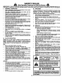
SAFETY
Practices RULES
for Ride-On
Safe Operation
Mowers
A
u
IMPORTANT: THIS CUTTING MACHINE IS CAPABLE OF AMPUTATING HANDS AND FEET AND THROWING OBJECTS.
FAILURE TO OBSERVE THE FOLLOWING SAFETY INSTRUCTIONS COULD RESULT iN SERIOUS INJURY OR DEATH.
I. GENERAL OPERATION
III. CHILDREN
•
Read, undemtand,and followell instructionsin the manual
Tragic accidents can occur if the operator is not alert to the
and on the machinebeforestarting.
presence of children. Children are often attracted to the
•
Only allow responsibleadults, who ere familiar with the
machine and the mowing activity. Never assume that
instructions,to operatethe machine.
children will remain where you last saw them.
•
Clear the area of ob ects such as rocks,toys, wire, etc.,
•
Keepchildrenoutofthe mowingarea and underthewatchful
wh c_ cou d be pickedup and thrownby the blade.
care of anotherresponsibleadult.
•
Be surethe area isclearofotherpeoplebeforemowing.Stop
Be alert and turnmachineoft if childrenenter the area.
machineif anyone enters the area.
•
Beforeand when backing,lookbehindand downfor small
•
Nevel"carry passengers.
children.
•
Do notmowin reverseunlessabsolutelynecessary.Always
•
Never carry children. They may fall off and be seriously
look downand behind beforeand while backing.
injuredor interferewith safe machineoperation.
•
Be aware of the mowerdischargedirectionanddo notpoint
•
Never allowchildrento operatethe machine.
it at anyone. Do not operatethe mowerwithouteitherthe
entiregrass catcher or the guard in place.
•
Use extra care when approachingblind comers, shrubs,
trees, or otherobjectsthat may obscurevision.
•
Slow down before turning.
•
Never leave a runningmachineunattended. Alwaystum off
IV. SERVICE
blades, set parking brake, stop engine, and remove keys
before dismounting.
•
Useextracare inhandlinggasolineandotherfuels.Theyare
flammableand vaporsare explosive.
•
Turn off bladeswhen not mowing.
Use onlyan approvedcontainer.
•
Stop engine before removing grass catcher or unclogging
chute.
Never remove gas cap or add fuel with the engine
running. Allowengine to cool beforerefueling. Do not
•
Mow only in daylightor goodartificiallight.
smoke,
•
Do not operate the machine while under the influenceof
Never refuelthe machineindoors.
alcoholor drugs.
Never storethe machineor fuel containerinsidewhere
•
Watch fortrafficwhen operatingnear or crossingroedways.
there isan openflame, suchas.a water heater.
•
Use extra care when loadingor unloadingthe machineinto
•
Never run a machineinsidea closedarea.
e traileror truck.
•
Keep nutsand belts,especiallybladeattachmentboltstight
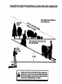
II. SLOPE OPERATION
and keep equipmentin goodcondition.
•
Never tamper with safety devices. Check their proper
Slopes are a major factor related to loss-of-control and
operationragulady.
tipover accidents, which can result in severe injury or
•
Keep machinefree ofgrass,leaves,or otherdebrisbuild-up.
death. All slopes require extra caution. If you cannot back
Clean oil or fuel spillage. Allow machine to cool before
up the slope or if you feel uneasy on it, do not mow it.
storing.
DO:
•
Stop and inspect the equipment if you strike an object.
Repair,if necessary,before restarting.
•
Mow up and downslopes,not across.
•
Never make adjustmentsor repairswiththeengine running.
•
Removeobstaclessuchas recks,tree limbs,etc.
•
Grasscatchercompenantsera subjecttowear, damage,and
•
Watch for holes, ruts, or bumps. Uneven terrain could
deterioration,which could expose moving parts or allow
overfumthe machine. Tall grasscan hide obstacles.
objectsto be thrown, Frequentlycheck componentsand
•
Use slowspeed. Choosea lowgear sothatyouwill not have
replacewithmanufacturer'srecommendedparts,when necto stop or shiftwhileon the slope.
essary.
•
Follow the manufacturer's recommendationsfor wheel
•
Mowerbladesare sharpand can cut. Wrap the blade(s)or
weightsor counterweightsto improvestability.
wear gloves,and use extra cautionwhen servicingthem.
•
Use extra care with grass catchers or other attachments.
•
Check brake operationfrequently. Adjust and serviceas
These can change the stabilityof the machine.
required.
•
Keep all movementon the slopesslow and gradual. Do not
make suddenchangesin speed or direction.
Look for this symbol to point out important
safety
precautions.
It
means
•
Avoid startingor stoppingon a slope. If tires lose traction,
disengagethe bladesand proceedslowlystraightdownthe
CAUTION!II
BECOME ALERTIn
YOUR
slope.
SAFETY IS INVOLVED.
DO NOT:
CAUTION: Always disconnect spark plug
•
Donottumonslopesunlessnecessary,andthen,tumslowly
and graduallydownhill,if possible.
wire end place wire where It cannot contact
•
Do not mow near drop-offs,ditches,or embankments.The
spark plug In order to prevent accidental
mowercouldsuddenlyturnover if a wheel isover the edge
starting when setting up, transporting,
of a cliffor ditch,or if an edge caves in.
adjusting or making repairs.
•
Do not mow on wet grass. Reduced tractioncould cause
sliding.
•
Donottrytostabilizethemachinebyputtingyourfootonthe
ground.
•
Do not use grass catcher on steep slopes.
The engine exhaust from this product contains
A WARNING A
chemicals known to the State of California to
cause cancer, birth defects, or other reproductive harm.
2
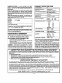
PRODUCT
CONGRATULATIONS
on your purchase of a Sears
Tractor. It has been designed, engineered and manufactured to give you the best possible dependability and
performance.
Should you experience any problem you cannot easily
remedy, please contact your nearest Sears Authorized
Service Center/Department. We have competent, welltrainedtechniciansand the propertoolsto serviceor repair
this tractor.
Please read and retain this manual. The instructionswill
enable you to assemble and maintainyourtractorproperly.
Always observe the "SAFETY RULES".
MODEL
NUMBER
SPECIFICATIONS
HORSEPOWER:
19.5
GASOLINE CAPACITY
ANDTYPE:
3.5 GALLONS
UNLEADED REGULAR
OIL TYPE (API-SF/SG/SH): SAE 30 (above 32°1=)
SAE 5Wo30 (below 32°F)
I
OIL CAPACITY:
3.0 PINTS
SPARK PLUG:
GAP: .030")
CHAMPION RJ19LM
VALVE CLEARANCE:
INTAKE:
.004" ÷ .006"
EXHAUST: .007" - .009"
GROUND SPEED (MPH):
FORWARD:
1st
2nd
3rd
4th
5th
6th
REVERSE:
917.259566
SERIAL
NUMBER
DATEOFPURCHASE
THEMODELANOSERIALNUMBERSWILLBEFOUND
ON A PLATE UNDER THE SEAT.
YOU SHOULD RECORD BOTH SERIAL NUMBER AND
! DATE OF PURCHASE AND KEEP IN A SAFE PLACE
I FOR FUTURE
REFERENCE.
MAINTENANCE
AGREEMENT
TIRE PRESSURE:
FRONT: 14 PSI
REAR:
10 PSI
CHARGING SYSTEM:
3 AMPS BATTERY
5 AMPS HEADLIGHTS
BATTERY:
AMPiHR:
MIN. CCA:
CASE SIZE:
BLADE BOLT TORQUE:
30-35 FT. LBS.
A Sears Maintenance Agreement is available on this product. Contact your nearest Sears store for details.
CUSTOMER RESPONSIBILITIES
1.1
1.4
2.3
3.5
4.5
5.7
1.8
30
240
UtR
with a spark arrastermeeting applicable localor state laws
(if any). If a spark arrester is used, it shouldbe maintained
in effectiveworkingorder by the operator.
In the state of California the above is required by law
(Section 4442 of the California Public Resources Code).
Other states may have similarlaws. Federal lawsapplyon
federal lands. A spark attester for the muffler is available
through your nearest Sears Authorized Service Center/
Department (See REPAIR PARTS sectionofthis manual).
Read and observe the safety rules.
Follow a regular schedule in maintaining, caring forand
using your tractor.
•
Follow the instructions under "Customer Responsibilities" and =Storage" sections of this owner's manual.
WARNING:
This tractor is equipped with an internal
combustion engine and should not be used on or near any
unimproved forest-covered, brush-covered or grass-covered land unless the engine's exhaust system is equipped
LIMITED TWO YEAR WARRANTY ON CRAFTSMAN RIDING EQUIPMENT
For two (2) years from the date of purchase, if thisCraftsman Riding Equipmentis maintained,lubricatedand tuned up according
to the instructionsin the owner's manual, Seam will repairor replace, free of charge, any parts found to be defective in material or
workmanship.
This Warranty does not cover:
Expendable items which become worn duringnormal use, such as blades,spark plugs,air cleaners, belts, etc.
Tire replacement or repaircaused by puncturesfrom outsideobjects,such as nails,thorns, stumps, or glass.
Repairs necessary because of operatorabuse, negligence, improperstorage or accident or the failure to maintain the
equipment accordingto the instructionscontainedin the owner's manual.
Ridingequipment used for commercialor rentalpurposes.
LIMITED 90 DAY WARRANTY ON BATTERY
For ninety (90) days from date of purchase, if any battery included with this riding equipment proves defective in material or
workmanshipand our testingdetermines the batterywill not hold a charge, Sears will replace the battery at no charge.
IN-HOME WARRANTY SERVICE ON YOUR CRAFTSMAN RIDING EQUIPMENT IS AVAILABLE AT NO-CHARGE FOR 30
DAYS FROM THE DATE OF PURCHASE. PLEASE CONTACT YOUR NEAREST SERVICE CENTER. AFTER 30 DAYS FROM
THE DATE OF PURCHASE, WARRANTY SERVICE IS AVAILABLE BY TAKING YOUR CRAFTSMAN RIDING EQUIPMENT TO
YOUR NEAREST SEARS SERVICE CENTER. (IN-HOME WARRANTY SERVICE WILL STILL BE AVAILABLE AFTER 30 DAYS
FROM THE DATE OF PURCHASE BUT A STANDARD TRIP CHARGE WILL APPLY.) THIS WARRANTY APPLIES ONLY
WHILE THIS PRODUCT IS IN THE UNITED STATES.
This Warranty gives you specificlegal rights,and you may also have other rightswhich may vary from state to state.
SEARS, ROEBUCK AND CO., D/817 WA, HOFFMAN ESTATES, IL 60179
3
TABLE OF CONTENTS
SAFETY RULES ............................................................ 2
PRODUCT SPECIFICATIONS ...................................... 3
CUSTOMER RESPONSIBILITIES ..................... 3, 15-19
WARRANTY .................................................................. 3
TABLE OF CONTENTS ................................................ 4
INDEX ............................................................................ 4
TRACTOR ACCESSORIES .......................................... 5
ASSEMBLY ................................................................ 7-9
OPERATION ........................................................
10-14
MAINTENANCE SCHEDULE ...................................... 15
SERVICE AND ADJUSTMENTS ............................ 2025
STORAGE ................................................................... 26
TROUBLESHOOTING ............................................ 27-28
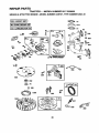
REPAIR PARTS - TRACTOR ................................. 30-47
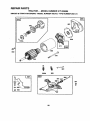
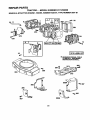
REPAIR PARTS - ENGINE .................................... 48-53
PARTS ORDERING/SERVICE .................. BACK PAGE
INDEX
A
Accessories............................................ 5
Adjustments:
Brake........................................... 22
Carburetor ................................... 25
Mower:
Front-To-Back........................ 21
Side-To-Side .......................... 21
Throttle ControlCable ................. 24
Air Filter, Engine ................................. 18
Air Screen, Engine ............................. 18
Assembly........................................... 7-9
B
Battery:
Charging .................................... 7-8
Cleaning ...................................... 17
Connecting................................. 7-8
Startingwith Weak Battery ......... 23
Storage ....................................... 26
Terminals .................................... 17
Belts:
Motion Drive
Removal/Replacement ........... 22
Mower Blade Ddve
Removal/Replacement........... 22
Blade:
Sharpening .................................. 16
Replacement ............................... 16
Brake Adjustment ............................... 22
C
Carburetor Adjustment....................... 25
Controls, Tractor ................................ 11
Customer Responsibilities............. 15-19
Engine:
Air Filter................................... 18
Air Screen, Engine .................. 18
Battery ..................................... 17
Cooling Fins, Engine ............... 18
Engine Oil ............................... 17
Fuel Filter................................ 19
Spark Plugs............................. 19
Tractor:
Blades ..................................... 16
LubricationChart ..................... 15
Maintenance Schedule ........... 15
Tire Care ......................... 8,16,23
Cutting Height, Mower ....................... 12
E
Electrical:
Intedocksand Relays ................. 24
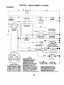
Schematic ................................... 29
Wiring Diagram ........................... 30
Engine:
Air Filter....................................... 18
Air Screen ................................... 18
Cooling Fins, Engine ................... 18
Oil Change .................................. 17
Oit Level ................................. 13,17
Oil Type ....................................... 17
Preparation ................................. 13
Repair Parts ........................... 48-53
Starting........................................ 14
Storage ....................................... 26
F
Filters:
Air ................................................ 18
Fuel ............................................. 19
Fuel:
Type ............................................ 13
Storage ....................................... 26
Fuse ................................................... 24
G
Gauge Wheels ..................................... 8
H
Hood Removal/Installation................. 24
L
LevelingM<)werDeck ......................... 21
LubdcationChart ................................ 15
M
Maintenance Schedule ...................... 15
Mower:
Adjustment,Front-to-Back.......... 21
Adjustment,Side-to-Side ............ 21
Blade Sharpening ....................... 16
Blade Replacement..................... 16
Cutting Height ............................. 12
Installation................................... 20
Operation .................................... 13
Removal ...................................... 20
Mowing Tips ....................................... 14
Muffler ................................................ 19
Spark Arrester .......................... 3,40
Mulcher Plate ....................................... 9
4
O
Oil:
Cold Weather Conditions....... 13,17
Engine........................... :_............ 17
Storage ....................................... 26
Operation ...................................... 11-14
Operating Mower ................................ 13
Options:
Accessodes................................... 5
Spark Arrester .......................... 3,40
P
Parking Brake................................ 11-12
Parts Bag ............................................. 6
Pads, Replacement/Repair ........... 30-47
ProductSpecifications........................... 3
R
Repair Parts .................................. 30-47
s
Safety Rules ......................................... 2
Seat ...................................................... 8
Service and Adjustments.............. 20-25
Brake........................................... 22
Carburetor................................... 25
Fuse ............................................ 24
Hood Removal/Installation.......... 24
MotionDrive Belt
Removal/Replacement........... 22
Mower Blade Drive Belt
Removal/Replacement........... 22
Mower Adjustment:
Frent-to-Back ......................... 21
Side-to-Side ........................... 21
Mower Installation....................... 20
Mower Removal .......................... 20
Tire Care ............................. 8,16,23
Slope Guide Sheet ............................. 55
Spark Plugs........................................ 19
Specifications....................................... 3
Startingthe Engine ....................... 13-14
Steedng Wheel ................................ 7,23
Stopping the Tractor ........................... 12
Storage ............................................... 26
T
Throttle Control Cable Adjustment ..... 24
Tires ........................................... 8,16,23
Trouble ShootingChart .................. 27-28
Transaxle Repair Parts................. 46-47
W
Warranty ............................................... 3
Widng Diagram .................................. 30
Wiring Schematic ............................... 29
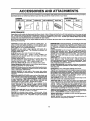
ACCESSORIES
AND ATTACHMENTS
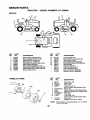
These accessories and attachmentswere available throughmostSears retailoutletsandservicecenterswhen the tractorwas purchased.
Most Sears stores can order these items for you when youprovide the model number of your tractor,
MAINTENANCE
ENGINE
SPARK PLUG
GASCAN
ENGINEOIL
FUEL STABILIZER
AIR FILTER
BLADES
BELTS
%
PERFORMANCE
Sears offersa wide variety of attachmentsthat fit yourtractor. Many ofthese are listedbelowwith briefexplanationsof how they can help
you. This listwas current st the time of publication;however, it may change in future years - more attachments may be added, changes
may be made in these attachments, or some may no longer be available or fit your model. Contact your nearest Sears store for the
accessories and attachments that are available for your tractor.
Most of these attachments do not require additional hitches or conversion kits (those that do are indicated) and are designed for easy
attaching and detaching.
SNOW BLADE forsnowremovalonly. 14-inch high,48-inch wide
blade clears 42-inch path whenangled leftor fight. Raises, lowers
with side lever. Ad ustableskids; replaceable, reversiblescraper
bar. (Use witht re cha nsand wbeelwe ghts and/or rear drawbar
weight.)
SNOWTHROWER has 40-inch swath. Drum-type auger handles
powdery and wet/heavy snow. Mounts easily with simple pin
arrangement. Discharge chuteadjusts from tractorseat. 6-inch
diameter spout dischargessnow 10 to 50 feet. Liffcontrolledat
tractor seat. (Use with chains and wheel weights and/or rear
drawbar weight.)
SPRAYERS use 12-volt DC electric motorthat connects to the
tractor battery or other t2-voit source. Includes booms for
automaticsprayingand hand held wandfor spot spraying. Wand
has adjustable spray pattern. For applying herbicides, insecticides, fungicides and liquidfertilizers.
SPREADER/SEEDERS make seeding, fertilizing, andweed killing easy. Broadcast spreaders are also useful for granular deicers and sand.
SWEEPERS letyou collectgrass clippingsand leaves.
TILLER has5 hp engine and36-inch swath toprepareseed beds,
cultivateand compostgarden residue. Tiller has its own built-in
liftanddepth controlsystem anddoes NOT require asleeve hitch.
Fitsany lawn, yard or gardentractor. Simplyhook up tothe tractor
drawber and go! Optional accessories convert unit for
dethatching,aerating, hilling...withouttools.
TIRE CHAINS are heavy duty;closely Spacedextra-large cross
linksgive smooth fide, outstandingtraction.
TRACTOR CAB has heavy duty vinylfabric over tubular steel
frame, ABS plastictop; clear plasticwindshieldoffers360 degree
visibility. Hinged metal doors with catch. Keeps operatorwarm
and dry. Remove vinyl sides and windshields for use as sun
protector in summer. Optional accessories include: tinted/
tempered solidsafety glasswindshieldwith hand operatedwiper;
12-voltamber caution lightfor mounting on cab top.
VACS for powerfulcollectionof heavygrassclippingsandleaves.
Optional wand attachment to pick up debris in hard-to-reach
places. VAC/CHIPPER includesa chipper-shredder.
WEIGHT BRACKET for drawbar for snow removal applications.
Uses (1) 55 Ib. weight.
WHEEL WEIGHTS for rear wheels provide needed tractionfor
snow removal or dozing heavy materials.
AERATOR promotes deep root growth for a healthy lawn, Tapered 2.5-inch steel spikes mounted on 10-inch diameter discs
puncture holes in soil at close intervals to let moisture soak in.
Steel weight trey for increased penetration.
BAGGER lets you collect grass clippings and leaves for a
healthier, nearer looking lawn. Two Permanex containers hold
30-gallon plastic bags.
BUMPER protects front end of tractor from damage.
CARTS make hauling easy. Variety of sizes available, plus
accessories such as side panel kits, tool caddy, cart cover,
protective mat and dolly.
CORING AERATOR takes small plugsout of soil to allow moisture and nutrients to reach grass roots. 36-inch swath. 24
hardened steel coringtips. 150 lb. capacity weight tray.
EASY OIL DRAIN VALVE makes oilchanges easier, faster.
FRONT NOSE ROLLER canters in front of mower decktoreduce
chances of =scalping" on uneven terrain.
GANG HITCH letsyoutow2 or 3 pull-behindattachmentsat once,
such as sweepers, dethatchers, aerators (not for use with rollers,
carts or other heavy attachments).
GAUGE WHEELS on both sides of the mower deck reduce
chances of =scalping" on uneven terrain. For mowerdecks notso
equipped.
MULCH RAKE/DETHATCHER loosenssoil and flips thatch and
mattedleaves to lawn surfaceforeasy pickup. Twenty springtine
teeth. Usefultoprepare bare areas for seeding. Availablefor front
or rear mounting. HIGH PERFORMANCE REEL-ACTION
SPRING TINE DETHATCHER covers 36-inch wide path and
tosses thatch into large hopper. Mounts behindtractor.
MULCHING CLOSE-OUT PLATE KIT, once installed, lets you
mulch, discharge or bag clippings (bagger optional) without
changingblades. For models not equipped as 3-in-1 Convertible
mowers. See "MOWER in the Repair Parts section of this
manual.
RAMP TOPS AND FEET let you load and unload tractorfrom a
pickup truck. Use with 2 x 8 or 2 x 10 lumber.
ROLLER for smoother lawn surface. 36-inch wide, 18-inch
diameter water-tightdrumholdsupto 390 Ibs.of weight, Rounded
edges prevent harm to turf. Adjustable scraper automatically
cleans drum.
5
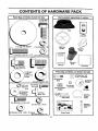
CONTENTS
Parts
Bag contents
shown
OF HARDWARE
full size
PACK
Parts packed separately in carton
(1) Hex Bolt
3/8-16 x 1
Seat
Video
Cassette
(1) Large Flat Washer
(1) Lockwasher 3/8
Steering
Wheel
Mulcher
Plate
1;:He':x:Bo;:t:5:i:16:::;:8x1-I/4(1)Locknut 5/16-18
Manual
(1) Shoulder
Bolt 5/16-18
Steering
Boot
Parts Bag
(1) Hex Bolt
1/2-13 x I
Parts bag contents not shown full size
17/32 x
1-3/16.x 12
(_(2)
(1) Washer
Gauge
_.
(2) Shoulder
Bolts
(1) Lock Washer 1/2
Q
Lock
__._
|
__J
_i=
(2)
Washers 3/8
x 7/8 x 14 Gauge
_
(2) Center-
Steering Wheel
Adapter
(2)
Screws
#10
x 5/8
Wheels
(2) Gauge
lock Nuts
(2) Keys
Was%
} (2) V_/ashers
/ 3/16 x 3/4
x 16 Gauge
k
Assemblys
Steering
Wheel
Insert
(2) Hex Bolts 1/4-20 x 3/4
@
Steering
Extension
Shaft
(2) Hex Nuts 1/4-20
(2) Washers 9/32 x 5/8 x 16 Gauge
12) Lock Washers 1/4
Slope Sheet
6
ASSEMBLY
Your new tractor has been assembledat the factorywith exception o4those parts left unassembledfor shippingpurposes.
To ensure safe and properoperation of yourtractorall parts and hardware you assemble mustbe tightenedsecurely. Use
the correcttools as necessary to insure propertightness.
TOOLS
REQUIRED
FOR ASSEMBLY
A socketwrench set willmake assembly easier. Standard
wrench sizes are listed.
(1) 3/4" Socket w/drive rachet
(2) 7/16" wrenches
PhillipsScrewdriver
(2) 1/2" wrenches
Tire pressure gauge
(1) 9/16" wrench
Utilityknife
When right or left hand is mentioned in this manual, it
means when you are in the operating position (seated
behind the steering wheel).
__3/8jE
INSERT
X BOLT
LOCK WASHER
LARGE FLAT
WASHER
TO REMOVE TRACTOR FROM CARTON
:STEERING'
WHEEL
UNPACK CARTON
•
Remove all accessible loose parts and parts cartons
from carton (See page 6).
Cut, from top to bottom,along lineson all four corners
of carton, and lay panels flat.
Check for any additional loose parts or cartons and
remove.
STEERING
ADAPTER_
BEFORE ROLLING TRACTOR OFF SKID
EXTENSION SHAFT
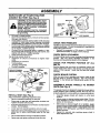
ATFACH STEERING
WHEEL (See Fig. 1)
ASSEMBLE EXTENSION SHAFT AND BOOT
5/16 HEX BOLT
•
Slide extension shaft onto lower steering shaft. Align
mounting holes in extension and lower shafts and
install 5/16 hex bolt and Iocknut. Tighten securely,
IMPORTANT: TIGHTEN BOLT AND NUT SECURELY TO
18-22 FT, LBS TORQUE.
•
Place tabs of steering boot over tab slots in dash and
push down to secure.
5/16LOCKNUT
INSTALL STEERING WHEEL
•
Positionfront wheels of the tractorso they are pointing
straightforward.
Slidesteering wheel adapterontosteeringshaftextension.
•
Positionsteering wheel so cross bars are horizontal
(left to right) and slide inside boot and onto adapter.
Assemble large flat washer, 318 lookwasher, 318 hex
bolt and tighten securely.
•
•
Snap steering wheel insert into center of steering
wheel.
•
Remove protective materials from tractor hood and
grill.
IMPORTANT:
CHECK
FOR AND REMOVE
LOWER
STEERING
SHAFt"
FIG. 1
TO ROLLTRACTOR
section for location
•
•
•
ANY STAPLES
IN SKID THAT MAY PUNCTURE TIRES WHERE TRACTOR
IS TO ROLL OFF SKID.
•
7
OFF SKID (See Operation
and function of controls)
Press liftlever plungerand raise attachmentlift leverto
its highest position.
Release parking brake by depressing clutch/brake
pedal.
Place gearshift lever in neutral (N) position,
Roll tractor backwards off skid.
Remove banding holding discharge guard up against
tractor.
ASSEMBLY
HOW TO SET UP YOUR TRACTOR
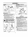
CONNECT BA'rrERY (See Fig. 2)
CAUTION: Do not short battery terminals by allowing a wrench or any other
object to contact both terminals at the
same time. Before connecting battery
remove meta bracelets, wristwatch
bands, rings, etc.
Positive terminal must be connected
first to prevent sparking from accidental grounding.
Lift hood to raised position.
Open terminal access doors, remove terminal protective caps and discard.
If this battery is put into service after month and year
indicated on label (label located between terminals)
charge battery for minimum of one hour at 6-10 amps.
•
First connect RED battery cable to positive (+) battery
terminal with hex bolt, flat washer, lock washer and hex
nut as shown. Tighten securely.
Connect BLACK grounding cable to negative (-) battery terminal with remaining hex bolt, flat washer, lock
washer and hex nut. Tighten securely.
Close terminal access doors.
Use terminal access doors for:
•
Inspection for secure connections (to tighten hardware).
•
Inspection for corrosion.
• Testing battery.
•
Jumping (if required).
•
Pedodic charging.
DISCARD TERMINAL
PROTECTIVE CAPS
HEX NUT
LOCK
WASHER
FLAT
WASHER
SEAT
SEAT PAN
SHOULDER
BOLT
r WASHER
ADJUSTMENT
BOLT
FIG. 3
CHECK
TIRE
PRESSURE
The tires on your tractorwere overinflatedat the factoryfor
shippingpurposes. Correct tire pressure is importantfor
best cutting performance.
Reduce tire pressure to PSI shown in "PRODUCT
SPECIFICATIONS" on page 3 of this manual.
CHECK
DECK
LEVELNESS
For best cuttingresults,mower housingshouldbe propedy
leveled, See "TO LEVEL MOWER HOUSING" in the
Service and Adjustmentssection of this manual.
CHECK
BELTS
FOR
PROPER
POSITION
OF
ALL
See the figures that are shown for replacing motion and
mower blade ddve belts in the Service and Adjustments
section of this manual. Verify that the belts are routed
correctly.
CHECK
BRAKE
SYSTEM
After you learn how to operate your tractor, check to see
that the brake is properly adjusted. See "TO ADJUST
BRAKE" in the Service and Adjustmentssection of this
manual,
ACCESS
DOOR
PosmvE
(RED)
CABLE
NEGATIVE
(BLAC_
CABLE
FIG. 2
INSTALL SEAT (See Fig. 3)
Adjust seat before tighteningadjustment bolt.
•
Remove cardboard packing on seat pan.
•
Place seat on seat pan and assemble shoulder bolt.
Tighten shoulder bolt securely.
•
Assembleedjustment bolt, lock washer and flat washer
loosely. Do not tighten.
Lower seat into operating position and sit on seat.
Slide seat until acomfortable position is reached which
allows you to press clutch/brake pedal all the way
down.
•
LOCK WASNER
Get off seat without moving its adjusted position.
Raise seat and tighten adjustment bolt securely.
ASSEMBLE GAUGE
DECK (See Fig. 4)
WHEELS
TO MOWER
The gauge wheels are designed to keep the mower deck in
proper positionwhen operating mower. Be sure they are
properlyadjustedto ensure optimummower performance.
•
Assemble gauge wheels with tractor on a flat level
surface.
Adjust mower to desired cuttingheight (See "TO ADJUST MOWER CU'I-]'ING HEIGHT" in the Operation
section of this manual).
With mower in desired height of cut position gauge
whee s shouldbeassembledso theyare slightlyoffthe
ground. Install gauge wheel in appropriate hole with
shoulder bolt, 3/8 washer, and 3/8-16 lecknut and
tighten securely.
Repeat for opposite side installing gauge wheel in
same adjustment hole.
ASSEMBLY
TO CONVERTTO
DISCHARGING
GAUGE WHEEL
MOUN_NG
BRACKET
\
BAGGING OR
Simply remove mulcher plate and store in a safe place.
Your mower is now ready for dischargingor installationof
optional grass catcher accessory.
DEFLECTOR
3/8-16
LOCKNUT
_8"WASHER
_SHOULDER
GAUGE
BOLT
FIG. 4
INSTALL MULCHER
PLATE
(See Figs. 5 & 6)
HOOKS
Install two latch hooks to mulcher plate using screw,
washer, lock washer, and weld nut as shown.
NOTE: Pre-assemble weld nut to latch hook by inserting
weld nut from the top with hook pointingdown.
•
Tighten hardware securely.
•
•
•
•
FIG. 6
,/CHECKLIST
Raise and hold deflector shield in uprightposition.
Place front of mulcher plate over frontof mower deck
opening and slide intoplace, as shown.
Hook front latch intohole on frontof mower deck.
Hook rear latch into hole on back of mower deck.
BEFORE YOU OPERATE AND ENJOY YOUR NEW
TRACTOR, WE WISH TO ASSURE THAT YOU RECEIVE
THE BEST PERFORMANCE AND SATISFACTION FROM
THIS QUALITY PRODUCT.
PLEASE REVIEW THE FOLLOWING CHECKLIST:
,/ All assembly instructionshave been completed.
,/ No remaining looseparts in carton.
guard from mower. Raise and ho|d
CAUTION:
guard
whenDoattaching
not remove
mulcher
discharge
plate
and allow it to rest on plate while in
operation.
WELD NUT FROM THE TOP
/
•/
,/
HOOK POINTS DOWN
,/
WELD
LOCK
WASHER
,/
Battery is properlyprepared and charged. (Minimum
1 hour at 6 amps).
Seat is adjusted comfortablyand tightened securely.
Alltires are properly inflated. (For shippingpurposes,
the tires were overinflatedat the factory).
Be sure mower deck is properly leveled side-to-side/
front-to-rear for best cutting results. (Tires must be
properly inflatedfor leveling).
Check mower and drive belts. Be sure theyare routed
properly around pulleys and inside all belt keepers.
,/
NUT_
Check wiring. See that all connectionsare stillsecure
and wires are properly clamped.
WHILE LEARNING HOW TO USE YOUR TRACTOR, PAY
EXTRA ATTENTION TO THE FOLLOWING IMPORTANT
ITEMS:
SCREW
LATCH
HOOK'--..
HOOK
LOCK
WASHER
WASHER
•/
,/
WELD
NUT
,/
WASHER
MULCHER
PLATE
/
'_""_SCREW
FIG. 5
9
Engine oil is at proper level
Fuel tank is filled with fresh, clean, regular unleaded
gasoline.
Become familiar with all controls- their locationand
function. Operate them before you startthe engine.
Be sure brake system is in safe operating condition.
OPERATION
These symbolsmay appear On yourtractor or in literaturesuppliedwiththe product. Learn and understandtheirmeaning.
BATFERY
CAUTION OR
WARNING
REVERSE
FORWARD
FAST
SLOW
ENGINE ON
ENGINE OFF
OIL PRESSURE
CLUTCH
LIGHTS ON
OVER TEMP
LIGHT
FUEL
CHOKE
MOWER HEIGHT
DIFFERENTIAL
LOCK
PARKING BRAKE
LOCKED
UNLOCKED
L
R N H L
i
REVERSE
MOWER LIFT
DANGER,
NEUTRAL
A'I-I'ACHMENT
CLUTCH ENGAGED
HIGH
LOW
ATTACHMENT
CLUTCH DISENGAGED
PARKING BRAKE
IGNITION
HYDROSTATIC FREEWHEEL
(Hydro Modelsonly)
KEEP HANDS AND FEET AWAY
10
OPERATION
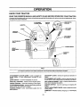
KNOW YOUR TRACTOR
READ THIS OWNER'S
MANUAL
AND SAFETY
RULES
BEFORE
OPERATING
YOUR
TRACTOR
Compare the illustrationswithyourtractorto familiarizeyou rself with the locationsofvanouscontrolsand adjustments. Save
this manual for future reference.
ATTACHMENT
CLUTCH LEVER
IGNITION
SWITCH
LIGHT SWITCH
POSITION
AMMETER
CHOKE
-
t
LIFT LEVER
THROTTLE
CONTROL
©
ATTACHMENT
CLUTCH/BRAKE
PEDAL
PARKING BRAKE
HEIGHT
ADJUSTMENT
KNOB
GEARSHIFT
FIG. 7
Our tractors conform to the safety standards of the American National Standards Institute.
ATFACHMENT CLUTCH LEVER: Used to engage the
mower blades, or other attachments mounted to your
tractor.
GEARSHIFT LEVER: Selects the speed and directionof
tractor.
A'I-rACHMENT LIFT LEVER: Used to raiseand lowerthe
mower deckor otherattachments mountedto yourtractor.
LIFT LEVER PLUNGER: Used to release attachment lift
lever when changing itsposition.
IGNITION SWITCH: Used for starting and stopping the
engine.
LIGHT SWITCH: Tums the headlightson and off.
THROTFLE CONTROL: Used to controlengine speed.
CHOKE CONTROL: Used when starting a cold engine.
CLUTCH/BRAKE PEDAL: Used for declutchingand brakingthe tractor and starting the engine.
PARKING DRAKE: Locks clutch/brake pedal into the
brake position.
HEIGHTADJUSTMENT KNOB: Used to adjustthemower
cuttingheight.
AMMETER: Indicates battery charging (+) or discharging
(-).
11
OPERATION
The operation of any tractor can result in foreign objects thrown into the eyes, which can
reau It In severe eye damage. Always wear safety glasses or eye shields while operating your
tractor or performing any adjustments or repairs. We recommend s wide vision safety mask
over the spectacles or standard safety glasses.
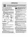
HOW TO USE YOUR TRACTOR
TO SET PARKING BRAKE (See Fig. 8)
Yourtractorisequippedwith an operatorpresencesensing
switch. When engine is running, any attempt by the
operatorto leave the seat without first setting the parking
brake willshut off the engine.
•
THROTTLE
CONTROL
ATTACHMENT CLUTCH LEVER
"ENGAGED" POSITION
CHOKE
CONTROL
"BRAKE"
POSITION
Always operate engine at fullthrottle.
TO USE CHOKE
CONTROL
PAR_NGBRAKE
TO MOVE FORWARD
(See Fig. 8)
"DISENGAGED"
POSmON
HEIGHT ADJUSTMENT KNOB
FIG. 8
(See Fig. 8)
MOWER BLADES Move attachment clutch lever to =DISENGAGED" position.
GROUND DRIVE -.
•
Depress clutch/brakepedal intofuit"BRAKE"position.
Move gearshift lever to neutral (N) position.
ENGINE •
Move throttle Controlto slow position.
NOTE: Failureto move throttlecontrolto slow position and
allowingengine to idle before stoppingmay cause engine
to "backfire".
Turn ignitionkey to "OFF" positionand remove key.
Always remove key when leaving tractor to prevent
unauthorizeduse.
Never use choke to stop engine.
NOTE: Under certain conditions when tractor is standing
idlewiththeengine running,hotengine exhaust gasesmay
cause "browning" of grass. To eliminate this possibility,
always stop engine when stoppingtrector on grass areas. 12
(See Fig, 8)
Usechoke controlwheneveryou are startinga coldengine.
Do not use to start a warm engine.
•
GEARSHIFT
LEVER
STOPPING
•
Operating engine at less than full throttlereduces the
battery charging rate.
Full throttleoffersthe best bagging and mower pedormance.
"DISENGAGED"
POSITION
POSITION
CLUTCH/BRAKE PEDAL
"DRIVE"POSDON
pletely, as described above, before leaving the operator's
to empty
CAUTION:
Always position;
stop tractor
comgrass catcher, etc.
TO USE THROTTLE CONTROL (See Fig. 8)
Depressclutch/brake pedal intofull =BRAKE" position
and hold.
Place parkingbrake lever in=ENGAGED"positionand
releasepressurefrom clutch/brakepedal. Pedal should
remainin =BRAKE" position. Make sure parkingbrake
will hold tractorsecure.
,,
{_
To engage choke control, pull knob out. Slowlypush
knob in to disengage.
AND BACKWARD
The directionand speed of movement,is controlledby the
gearshift lever.
Start tractor with clutch/brake pedal depressed and
gearshift lever in neut_l (N) position.
•
Move gearshiftand range shift levers to desired position.
•
Slowly release clutchibreke pedal to start movement.
IMPORTANT: BRING TRACTOR TO A COMPLETE STOP
BEFORE SHIFTING OR CHANGING GEARS. FAILURE
TO DO SO WILL SHORTEN THE USEFUL LIFE OF YOUR
TRANSAXLE.
TO ADJUST MOWER
(See Fig. 8)
CUTTING
HEIGHT
The cuttingheight is controlledbyturningthe heightadjustment knob in desired direction.
•
Turn knob clockwise(f_()
to raise cutting height.
•
Turn knob counterclockwise (_)to
height.
lower cutting
The cuttingheight range isapproximately 1-1/2" to 4". The
heights are measuredfrom the ground to the blade tip with
the engine not running. These heights are approximate
and may vary depending upon soil conditions, height of
grass and types of grass being mowed.
•
The average lawn should be cut to approximately 2-1/2
inches during the cool season and to over 3 inches
during hot months. For healthier and better looking
lawns, mow often and after moderate growth.
•
For best cutting pedormance grass over 6 inches in
height shouldbe mowed twice. Make the first cut
relatively high; the second to desired height.
OPERATION
TO OPERATE
(See Fig. 9)
MOWER
Yourtractor isequippedwith anoperatorpresencesensing
switch. Any attemptby the operatorto leave the seat with
the engine runningand the attachment clutchengaged will
shut off the engine.
•
Select desired height of cut.
•
Lower mower with attachment lift control.
•
TOrestartmovement,slowlyrelease parkingbrake and
clutch/brakepedal.
•
Make all turns slowly.
TO TRANSPORT
•
Start mower blades by engaging attachment clutch
control.
•
•
TO STOP MOWER BLADES - disengageattachment
clutchcontrol
BEFORE STARTING THE ENGINE
AI"rACHMENT CLUTCH LEVER
CHECK
"ENGAGED"
POSITION
_,_
_\
)_
/
/
When pushingor towing yourtractor, be suregearshift
lever is in neutral (N) position.
Do not push or tow tractor at more than five (5) MPH.
NOTE: To protect hood from damage when transporting
yourtractoronatruckor atrailer, besure hoodisclosedand
securedtotractor. Usean appropriatemeans oftyinghood
to tractor (rope, cord, etc.).
without either the entire grass catcher,
on
mowers Do
so not
equipped,
disCAUTION:
operate or
thethe
mower
charge guard in place.
"DISENGAGED" POSITION
Raise attachment lift to highest positionwith attachment liftcontrol.
/
/
ENGINE
OIL LEVEL
(See Fig. 15)
The engine in yourtractor hasbeen shipped,from the
factory, already filled with summer weight oil.
ATrACHMENT
LIFT LEVER
HIGH POSITION
gwiTI°N
•
•
Check engine oil with tractoron level ground.
Remove oilfillcap/dipstickand wipe clean, reinsertthe
dipstickand screw cap tight, wait for a few seconds,
remove and read oil level. If necessary, add oil until
"FULL"mark on dipstickis reached. Do not overfill.
•
For cold weather operation you shouldchange oil for
easier starting(See "OIL VISCOSITY CHART" in the
Customer Responsibilitiessection of this manual).
To change engine oil, see the Customer Responsibilities sectionin this manual.
•
ADD GASOLINE
•
Fill fuel tank. Use fresh, clean, regular unleaded
gasolinewithaminimumof87octane. (Useof leaded
gasolinewillincrease carbon and lead oxidedeposits
and reduce valve life). Do not mix oil with gasoline.
Purchasefuel in quantitiesthat can be usedwithin30
days to assure fuel freshness.
IMPORTANT: WHEN OPERATING IN TEMPERATURES
BELOW32 °F(0°C), USE FRESH, CLEAN WINTERGRADE
GASOLINE TO HELP INSURE GOOD COLD WEATHER
STARTING.
FIG. 9
TO OPERATE
I _
ON HILLS
hills with slopes greater than 15° and
CAUTION:
not any
driveslope.
up or down
do
not drive Do
across
WARNING: Experience indicates that alcohol blended
fuels (called gasehol or using ethanol or methanol) cart
attract moisturewhichleadsto separationand formation of
acids during storage. Acidic gas can damage the fuel
system of an engine while in storage. To avoid engine
problems,the fuel system shouldbe emptied beforestorage of 30 days or longer. Drain the gas tank, start the
engine and let it run untilthe fuel linesand carburetorare
empty. Use fresh fuel next season. See Storage Instructions for additional information. Never use engine or
carburetorcleaner productsin the fuel tank or permanent
damage may occur.
I
Choose the slowest speed before starting up or down
hills.
Avoid stopping or changing speed on hills.
If slowing is necessary, move throttle control lever to
slower position.
If stoppingis absolutelynecessary, pushclutch/brake
pedal quickly to brake position and engage parking
brake.
Move gearshift lever to 1st gear. Be sure you have
allowed room for tractor to roll slightly as you restart
movement.
I
CAUTION: Fill to bottom of gas tank
filler neck. Do not overfill. Wipe off any
spilled oil or fuel. Do not store, spill or
use gasoline near an open flame.
13
|
I
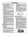
OPERATION
in the opposite direction making left hand turns until
finished (See Fig. 10 ).
If grass is extremely tall, it,should be mowed twice to
reduce load and possible Tire hazard from dded clippings. Make first cut relatively high; the second to the
desired height.
Do not mow grass when it is wet. Wet grass will plug
mower and leave undesirable clumps. Allow grass to
dry before mowing,
Always operate engine at full throttle when mowing to
assure better mowing performance and proper discharge of material. Regulate ground speed by selecting a low enough gear to give the mower cutting
performance as well as the quality of cut desired.
When operating attachments, select a greund speed
that will suit the terrain and give best performance of
the attachment being used.
TO START ENGINE (See Fig. 8)
When starting the engine for the first time or if the engine
has run out of fuel, it willtake extra crankingtime to move
fuel from the tank to the engine.
•
Sit on seat in operating position, depress clutch/brake
pedal and set parking brake.
•
Place gear shift lever in neutral (N) position.
Move attachment clutch to "DISENGAGED" position.
• Move throttle control to fast position
Pull choke control out for a cold engine start attempt.
For a warm engine start attempt the choke control may
not be needed.
Note: Before starting, read the warm and cold starting
procedures below.
Insert key into ignition and tum key clockwise to =START"
position and release key as soon as engine starts. Do
not run starter continuously for more than fifteen seconds per minute. If the engine does not start after
several attempts, push choke control in, wait a few
minutes and try again. If engine still does not start, pull
the choke control out and retry.
WARM WEATHER STARTING (50 ° F and above)
•
When engine starts, slowlypushchoke controlin until
the engine begins to run smoothly. If the engine starts
to run roughly, pull the choke control out slightly for a
few seconds and then continue to push the control in
slowly.
•
The attachments and grounddrive can now be used. If
the enginedoes not accept the load, restart the engine
and allow it to warm up for one minute using the choke
as described above.
COLD WE.ATHER STARTING (50° F and below)
•
When engine starts, slowly push choke controlin until
the engine begins to run smoothly. Continue to push
the choke controlin small steps allowingthe engineto
accept small changes in speed and load, until the
choke control is fully in, If the engine starts to run
roughly, pull the choke control out slightlyfor a few
seconds and then continue to push the control in
slowly. This may require an engine warm-up period
from several seconds to severa/minutes, depending
on the temperature.
• The attachments can be used dudng the engine warmup period and may require the choke control be pulled
out slightly.
NOTE: If at a high altitude (above 3000 feet) or in cold
temperatures (below 32 F) the carburetorfuel mixture may
need to be adjusted for best engine performance. See "TO
ADJUST CARBURETOR" in the Service and Adjustments
sectionof this manual.
MOWING
•
•
•
1
FIG. 10
MULCHING
TIPS
Tire chainscannot be used when the mowerhousingis
attached to tractor.
Mower should be propedy leveled for best mowing
performance. See "TO LEVEL MOWER HOUSING" in
the Service and Adjustmentssectionof this manual.
The left hand side of mower should be used for tdmming.
Drive so that clippingsare discharged onto the area
that has been cut. Have the cut area to the rightofthe
tractor. This will result in a more even distributionof
clippingsand more uniformcutting.
When mowing large areas, start by turning to the right
so that clippings will discharge away from shrubs,
fences, driveways, etc. After one or two rounds, mow
MOWING TIPS
IMPORTANT:
FOR BEST PERFORMANCE, KEEP
MOWER HOUSING FREE OF BUILT-UP GRASS AND
TRASH. CLEAN AFTER EACH USE.
•
The special mulching blade wilt recut the grass clippings many times and reduce them in size so that as
they fall onto the lawn they willdisperse intothe grass
and not be noticed. Also, the mulched grass will
biodegrade quicklyto provide nutrientsfor the lawn.
Always mulchwith your highestengine (blade) speed
as this will provide the best recuttingaction of the
blades.
•
Avoidcuttingyourlawn when it iswet. Wet grasstends
toform clumpsand interfereswiththe mulchingaction.
The best time to mow your lawn isthe early afternoon.
At thistime the grass has dried and the newlycut area
will not be exposedto the direct sun.
•
Forbestresults,adjustthemower cuttingheightsothat
the mower cuts off onlythe top one-thirdof the grass
blades (See Fig. 11). For extremely heavy mulching,
reduce your widthof cut and mow slowly.
•
Certain types of grass and grass conditionsmay require that an area be mulched a second time to completely hide the clippings. When doing a secondcut,
mow across or perpendicularto the first cut path.
Change yourcuttingpatternfrom week to week. Mow
northto southone week then changetoeast towest the
next week. This willhelp preventmattingand graining
of the lawn.
.,x,o
14
FIG. 11
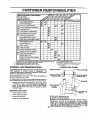
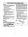
CUSTOMER
RESPONSIBILITIES
.A,NTENANCE
SCHEOULE
F,LL
'"OATEB
CEDATES
REGULAR SERVICE
Check Tire Pressure
Check Brake Operation
T
_
Cheek for Loose Fasteners
Sharpen/Replace Mower Blades
1_7
I_,=
V'
Lubrication Chart
If
TO Check Battery Level/Recharge
Clean Battery and Terminals
R
I_
Check Transaxle Cooling
k/
Adjust Blade BeLt(s) Tension
q_#'s
Adjust Motion Ddve Belt(s) Tension
_Jl's
Check Engine Oil Level
Change Engine Oil
I1 /
V w
.
_1
_
_1,2.3
E
Clean Air Filter
Clean Air Screen
G
Inspect Muffler/Spark Arrester
I
Replace Oil Filter (If equipped)
1_1,2
Replace Spark Plug
Clean Engine Cooling Fins
Replace Air Filter Paper Cartridge
_i
N
_2
1#'2
I,/
V'
Replace Fuel Fitter
1234-
I_
Change more oftenwhen operating under a heavy load or in high ambient temperatures.
Service more oftenwhen operating in dirly or dusty conditions.
If equipped with oil tilter,change oil every 50 hours.
Replace blades more oftenwhen mowingin sandy soil.
5 - If equipped with adjustable system,
6 - Not raquirad ifequipped with maintenance-free battery.
7 - Tighten front axle pivot bolt to 35 ft.-Ibs, maximum,
DO not ovedighten,
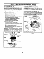
LUBRICATION
GENERAL RECOMMENDATIONS
The warrantyon this tractor does not cover items thathave
been subjected to operator abuse or negligence. To
receivefull value from thewarranty, operatormust maintain
tractor as instructedin this manual.
CHART
_
(_
®FRONT
SPINDLEW
ZERK-_
HEEL
BEARING ZERK
Some adjustments will need to be made periodically to
properlymaintain yourtractor.
SPINDLE ZERK (_)
't--1:::::::::::::::::::::
I
;.,
All adjustmentsin the Service and Adjustmentssectionof
this manualshouldbe checked at least once each season.
Once a year you should replacethe spark plug, clean
or replace air filter, and check blades and belts for
wear. A new spark plug and clean air filter assure
proper air-fuel mixture and help your engine run better
and last longer.
BEFORE
EACH
CLUTCH
PIVOT(S)
USE
(_ ATTACHMENT"
!
Check engine oil level.
Check brake operation,
(_) SAE 30 OR IOW30 MOTOR OIL
Check tire pressure.
Check for loosefasteners.
(_ GENERAL PURPOSE GREASE
(_) REFER TO CUSTOMER RESPONSIBILITIES "ENGINE" SECTION
IMPORTANT:
DO NOT OIL OR GREASE THE PIVOT POINTS
WHICH HAVE SPECIAL NYLON BEARINGS.
VISCOUS LUBRICANTS WILL ATTRACT DUST AND DIRT THAT WILL SHORTEN
THE LIFE OF THE SELF-LUBRICATING
BEARINGS.
IF YOU
FEEL THEY MUST BE LUBRICATED,
USE ONLY A DRY, POWlS
OERED GRAPHITE
TYPE LUBRICANT
SPARINGLY.
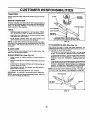
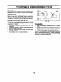
CUSTOMER
RESPONSIBILITIES
TRACTOR
BLADE
Alwaysobserve safety ruleswhen performingany maintenance.
_
MANDREL
BRAKE OPERATION
If tractorrequires more than six (6) feet stoppingdistance
at highspeed in higbestgear, then brake mustbe adjusted.
(See 'I"O ADJUST BRAKE" in the Service and Adjustments section of this manual).
IJA°SEMDLV
TRAIUNG EDGE
FLAT WASHER _
_
I
TIRES
•
LOCK
WASHER
HEXeOLT.
GRADE,,
Maintain proper air pressure in all tires (See "PRODUCT SPECIFICATIONS" on page 3 of this manual).
Keep tires free of gasoline, oil, or insect control chemicals which can harm rubber.
,. •
*A GRADE 8 HEAT TREATED BOLT CAN BE
IDENTIFIED BY SIX UNES ON THE BOLT HEAO.
Avoid stumps, stones, deep ruts, sharp objects and
other hazards that may cause tire damage.
FIG. 12
NOTE: To seal tire punctures and prevent flat tires due to
slow leaks, tire sealant may be purchased from your local
parts dealer. Tire sealant also prevents tire dry rot and
corrosion.
BLADE
TO SHARPEN BLADE (See Fig. 13)
Care should be taken to keep the blade balanced. An
unbalancedbladewillcause excessivevibrationand eventual damage to mower and engine.
CARE
For best results mower blades must be kept sharp, Replace bent or damaged blades,
•
BLADE REMOVAL
(See Fig. 12)
Raise mower to highest position to a_lowaccess to
blades.
•
Remove hex bolt, leckwasher andflatwasher securing
blade.
•
Install new or resharpened blade with trailingedge up
towards deck as shown.
!
The blade can be sharpenedwitha file or on a grinding
wheel. Do not attempttosharpen whileon the mower.
To check blade balance, you will need a 5/8" diameter
steel bolt,pin, or a cone belancer. (When usinga cone
balancer, follow the instructions-suppliedwith balancer).
•
Slidebladeon to anunthreadedportionofthe steelbolt
or pin and holdthe boltor pin parallelwith the ground.
If blade is balanced, it should remain in a horizontal
position. If either end of the blade moves downward,
sharpen the heavy end untilthe blade is balanced.
NOTE: Do not use a nattfor balancingblade. The lobes of
the center hole may appear to be centered, but are not.
Reassemble hex bolt, lock washer and flat washer in
exact order as shown.
•
Tighten bolt securely (30-35 Ft. Lbs. torque).
IMPORTANT: BLADEBOLTIS GRADE 8 HEATTREA]'ED.
NOTE: We do notrecommendsharpeningblade- but ifyou
do, be sure the blade is balanced.
CENTER HOLE
/
/
,. ADE
OR PIN _
FIG. 13
16
CUSTOMER
RESPONSIBILITIES
BATFERY
NOTE: Althoughmulti-viscosity oils (5W30, lOW30 etc.)
improve startingin coldweather, these multi-viscosityoils
will resultin increased oilconsumptionwhen used above
32°F. Checkyour engine oillevel more frequentlytoavoid
possibleengine damage from runninglow on oil.
Your tractor has a battery charging system which is sufficient for normal use. However, periodic charging of the
battery with an automotive charger will extend its life.
Keep battery and terminals clean.
Keep battery bolts tight.
Change the oilafter every 25 hours ofoperationor at least
once a year ifthe tractorisnot usedfor25 hoursinone year.
Keep small vent holes open.
Recharge at 6-10 amperes for 1 hour,
TO CLEAN BATTERY AND TERMINALS
Check the crankcase oil level before starting the engine
and after each eight (6) hours of operation. Tighten oil fit_
cap/dipsticksecurely each time you check the oil level.
Corrosion and dirt on the battery and terminals can cause
the battery to "leak" power.
TO CHANGE ENGINE OIL (See Figs. 14 and 15)
•
Determine temperature range expected before oil change.
All oil must meet API service classificationSF, SG or SH.
Be sure tractor is on level surface.
Remove terminal guard.
•
Disconnect BLACK battery cable first then RED battery cable and remove battery from tractor.
•
•
Rinse the battery with plain water and dry.
Clean terminals and batterycable endswithwire brush
untilbright.
Coat terminals with grease or petroleumjelly.
•
•
Reinstall battery (See "CONNECT BATTERY" in the
Assembly section of this manual).
•
•
Oil will drain more freely when warm.
Catch oil in a suitable container.
•
Remove oil flUcap/dipstick. Be carefulnot to allow dirt
to enter the engine when changing oil.
Remove drain plug.
•
Afteroil has drained completely,replaceoil drain plug
and tighten securely.
Refill engine with oilthroughoil fill dipsticktube. Pour
slowly. Do not overfill. For approximatecapacltysee
=PRODUCT SPECIFICATIONS" on page 3 of this
manual.
•
Use gauge on oilfill cap/dipstickfor checkinglevel. Be
sure dipstick cap is tightened securely for accurate
reading. Keep oil at "FULL"line on dipstick.
V-BELTS
Check V-belts for deterioration and wear after 100 hoursof
operation and replace if necessary. The belts are not
adjustable. Replace belts if they begin to slip from wear.
TRANSAXLE
COOLING
Keep transaxle free from build-upof dirt and chaff which
can restrictcooling,
OIL
_
AIR SCREEN
ENGINE
LUBRICATION
Only use high quality detergent oil rated with API service
classificationSF, SG or SH. Select the oil's SAE viscosity
grade according to your expected operating temperature,
°I s,s,cK
SAE VISCOSITY GRADES
FIG. 15
_20_
.30 •
0o
-20 o
TEMPERATURE
.10 _
0°
10 °
20 °
30°
RANGE ANTICIPATED BEFORE NEXT OiL CHANGE
FIG, 14
17
CUSTOMER
RESPONSIBILITIES
(See Fig. 16)
AIR FILTER (See Fig. 16)
CLEAN
Your engine will not run properly using a dirty air filter,
Clean the foam pre-cleaner after every 25 hoursof operation or every season. Service paper cartridge every 100
hoursofoperationor every season,whicheveroccursfirst.
Air screen must be kept free of dirt and chaff to prevent
engine damage from overheating. Clean with e wire brush
or compressed air to remove dirt and stubborndded gum
fibers.
Service air cleaner more often under dusty conditions.
•
Remove knob(s) and cover.
TO SERVICE PRE-CLEANER
ENGINE
•
•
Slide foam pre-cleaner off cartridge.
Wash it in liquid detergent and water.
•
•
Squeeze it dry in a clean cloth.
Saturate it in engine oil. Wrap it in clean, absorbent
cloth and squeeze to remove excess oil.
If very dirtyor damaged, replace pre-cleaner.
Reinstall pre-cleaner over cartridge.
f
•
Remove wing nuts and cartridge plate.
•
Carefully remove cartridge to preventdebris from entering carburetor.
Cleancartridgebytappinggentlyonflatsurtace. Ifvery
dirty or damaged, replacecartridge.
•
•
COOLING
FINS (See Fig. 17)
Remove any dust, dirt or oil from engine cooling fins to
preventengine damage from overheating.Air guidecovers
mustbe removed.Remove side panels and hood(See "TO
REMOVE HOOD AND GRILL ASSEMBLY" in the Service
and Adjustmentssectionof this manual).
•
Reinstallcover and secure with knob(s).
TO SERVICE CARTRIDGE
•
AIR SCREEN
ENGINE
COOLING FINS
<_
Reinstall cartridgeplate, wing nuts,precteaner, cover
and secure with knob(s).
IMPORTANT;
PETROLEUM SOLVENTS, SUCH AS
KEROSENE, ARE NOT TO BE USED TO CLEAN THE
CARTRIDGE. THEY MAY CAUSE DETERIORATION OF
THE CARTRIDGE. DO NOT OIL CARTRIDGE. DO NOT
USE PRESSURIZED
AIR TO CLEAN OR DRY
CARTRIDGE.
&
AIR GUIDE COVER (BOT H SIDES)
FIG. 17
PLATE
FOAM
AIR SCREEN
:ARTRIDGE
FIG. 16
18
CUSTOMER
RESPONSIBILITIES
MUFFLER
CLAMP
Inspectend replace corroded mufflerand spark attester (if
equipped) as itcould create a fire hazard and/or damage.
CLAMP
SPARK PLUGS
Replace spark plugs at the beginning of each mowing
season or after every 100 hours of operation, whichever
occurs first. Spark plug type and gap settingare shownin
"PRODUCT SPECIFICATIONS" on page 3 ofthis manual.
IN-LINE
FUEL
FILTER
FUEL
RLTEI
(See Fig. 18)
FIG. 18
The fuel filtershouldbe replacedonce each season. Iffuel
filterbecomes clogged, obstructingfuel flowto carburetor,
replacement is required.
CLEANING
•
With engine cool, remove filter and plug fuel line
sections.
•
•
Place new fuel filter in positionin fuel line with arrow
pointingtowards carburetor.
Keep finished surfaces and wheels free of all gasoline,
oil, etc.
•
Be sure there are no fuel line leaks and clamps are
properly positioned.
Immediately wipe up any spilledgasoline.
Protect painted surfaces with automotive type wax.
•
Clean engine, battery, seat, finish, etc. of all foreign
matter.
We do not recommend using a garden hose to clean your
tractor unlessthe electrical system, muffler, air filter and
carburetorare covered to keep water out. Water in engine
can resultin a shortenedengine life.
19
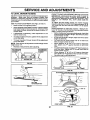
SERVICE
AND ADJUSTMENTS
CAUTION: BEFORE PERFORMING ANY SERVICE OR ADJUSTMENTS:
Depress clutch/brake pedal fully and set parking brake.
Place gearshift lever in neutral (N) position.
Place attachment clutch in "DISENGAGED" position.
Turn ignition key "OFF" and remove key.
Make sure the blades and all moving parts have completely stopped.
Disconnect spark plug wire from spark plug and place wire where it cannot come in contact with
plug.
TRACTOR
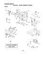
TO REMOVE MOWER (See Fig. 19)
Mowerwillbe easier'toremove fromthe rightside oftractor,
•
•
•
•
•
Place attachment clutch in "DISENGAGED" position.
Move attachmentliftlever forwardtolower mowerto its
lowest position.
Roll belt off engine pulley.
Disconnectclutch rod from clutch lever by removing
retainer spring.
Disconnect anti-sway bar from chassis bracket by
removingretainer spring.
Disconnectsuspensionarms from rear deck brackets
by removing retainer springs.
Disconnectfront linksfrom deck by removingretainer
springs,
Raise lift lever to raise suspensionarms. Slide mower
out from under tractor,
RETAINER
SPRING
IMPORTANT:
IF AN ATTACHMENT OTHER THAN THE
MOWER IS TO BE MOUNTED
TO THE TRACTOR,
REMOVE THE FRONT LINKS.
ANTI-SWAY BAR
TO INSTALL
MOWER (See Fig. 19)
Raise attachment lift lever to its highest position.
•
Slide mower undertractorwith dischargeguardto right
side of tractor.
•
•
Lower lift lever to its lowest position.
Install mower in reverse order of removalinstructions.
RETAINER
SPRINGS
(BOTH SIDES)
FIG. 19
20
SERVICE
AND ADJUSTMENTS
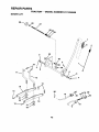
TO LEVEL MOWER HOUSING
Adjust the mower while tractor is parked on level groundor
driveway. Make sure tires are properly inflated (See
"PRODUCT SPECIFICATIONS" on page 3 of this manual).
If tires are over or underinflated, you will not properly adjust
your mower.
FRONT-TO-BACK ADJUSTMENT (See Figs. 22 and 23)
IMPORTANT: DECK MUST BE LEVEL SIDE-TO-SIDE. IF
THE FOLLOWING FRONT-TO-BACK ADJUSTMENT IS
NECESSARY, BE SURE TO ADJUST BOTH FRONT LINKS
EQUALLY SO MOWER WILL STAY LEVEL SIDE-TOSIDE.
To obtain the best cutting results, the mower housing
shouldbe adjustedsothat thefront is approximately1/8"to
1/2" lower than the rear when the mower is in its highest
position.
Check adjustment on right side of tractor. Measure distance"D" directlyinfront and behindthe mandrelat bottom
edge of mower housingas shown.
•
Beforemakingany necessaryadjustments,checkthat
bothfront linksare equal in length.Bothlinksshouldbe
approximately10-3/8".
•
If linksare not equal in length,adjustone linkto same
length as other link.
• To lower front of mower loosen nut "E" on both front
linksan equal numberof turns.
•
When distance "D" is 1/8" to 1/2" lower at front than
rear, tighten nuts "P against trunnion on both front
links.
•
To raisefront of mower,loosennut"F" from trunnionon
bothfront links. Tighten nut "E" on both front linksan
equal number of turns.
•
When distance "D" is 1/8" to 1/2" lower at front than
rear,tightennut"F"againsttrunnionon both front links.
•
Recheck side-to-side adjustment.
SIDE-TO-SIDE ADJUSTMENT (See Figs. 20 and 21)
•
Raise mower to its highest position.
•
At the midpointof bothsidesof mower,measure height
from bottomedge of mower to greund. Distance=A"on
bothsides of mower shouldbe the same or within 1/4"
of each other.
If adjustment is necessary, make adjustment on one
side of mower only.
To raise one side of mower,tighten lift linkadjustment
nut on that side.
•
To lower one side of mower, loosen lift link adjustment
nut on that side.
NOTE: Each fullturnof adjustmentnut willchangemower
height about 1/8".
•
Recheck measurements after adjusting.
BOTTOM EDGE
OF MOWER TO
GROUND
BOTTOM EDGE
OF MOWER TO
GROUND
MANDREL
FIG. 20
S SM"ENS'ON
FIG. 22
BOTH FRONTLINKSMUSTBE EQUALIN LENGTH
UFT MNK
ADJUSTMENT NUT
FIG. 21
NUT "E"
NUT
FRONT LINKS
21
TRUNNION
FIG. 23
SERVICE
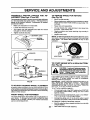
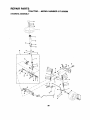
TO REPLACE
MOWER
BLADE
AND ADJUSTMENTS
DRIVE
BELT
WITH
PARKING
BRAKE
"ENGAGED"
(See Fig. 24)
The mower blade drivebelt may be replaced withouttools.
Park the tractor on level surface. Engage parkingbrake.
BELT REMOVAL •
Remove mower from tractor (See "TO REMOVE
MOWER" in this section of this manual).
NUT"A"
JAM NUT
•
Work belt off both mandrel pulleys and idler pulleys.
•
Pull belt away from mower.
BELT INSTALLATION •
Install new belt in reverse order of removal.
•
Make surebelt is inall pulleygroovesand insideall belt
guides.
Install mower in reverse order of removal instructions.
FIG. 25
MANDREL
PULLEY
IDLER
PULLEYS
TO REPLACE
(See Fig. 26)
MOTION
DRIVE
BELT
Park the tractoron level surface. Engage parkingbrake.
For assistance, there is a belt installationguide decal on
bottom side of left footrest.
•
Remove mower (See "TO REMOVE MOWER" in this
sectionof this manual.)
•
Remove upper belt keeper.
Remove belt from stationary idlerand clutchingidler.
Pull belt slack toward rear of tractor. Remove belt
upwardsfrom transaxlepulley bydeflectingbelt keepers.
•
•
MANDREL
PULLEY
•
Install new belt by reversingabove procedure.
IMPORTANT: MAKE SURE UPPER BELT KEEPER IS
POSITIONED PROPERLY BETWEEN LOCATOR TAB.
FIG. 24
TO ADJUST
BRAKE
Pullbelttowardfrontoftractorand remove downwards
from aroundengine ,pulley.
(See Fig. 25)
ENGINE_
PULLEY
Your tractor is equipped with an adjustable brake system
which is mounted on the right side of the transaxle.
-LOCATOR
TABS
CLUTCHING
IDLER
If tractorrequires more than six (6) feet stoppingdistance
at highspeed inhighestgear, then brake mustbe adjusted.
•
•
UPPER BELT
KEEPER
Depressciutch/'prakepedaland engage parkingbrake.
Measure distance between brake operating arm and
nut "A" on brake rod.
STATIONARY _
IDLER
Ifdistance isotherthan 1-1/2", loosen jam nutand turn
nut =A"until distance becomes 1-1/2". Retightenjam
nut against nut "A".
Roadtest tractorfor properstopping'distanceas stated
above, Readjust if necessary. If stoppingdistance is
still greater than six (6) feet in highest gear, further
maintenance is necessary. Contactyour nearest authorized service center/department.
TRANSAXLE
PULLEY
FIG. 26
22
SERVICE
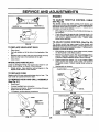
TRANSAXLE
SHIFTER
LINKAGE
AND ADJUSTMENTS
AND
AD-
JUSTMENT
(See Figs. 27 and 28)
The transaxle shouldbe in neutralwhen the gear shiftlever
isin the neutral (N) (lock gate) position. The adjustmentis
preset at the factory; however, if adjustment is needed,
proceed as follows:
•
•
Make sure transaxle is in neutral (N).
Loosen two Iocknutson tie rod.
•
Turn center rod until gearshift lever falls into neutral
lock gate on fender console.
Tighten Iocknutssecurely.
TO REMOVE WHEEL FOR REPAIRS
(See Fig. 29)
•
Remove axlecover, retainingringand washerstoallow
wheel removal(rear wheel containsa square key - Do
not lose).
•
Repair tire and reassemble.
On rear wheels only: align grooves in rear wheel hub
and axle. Insert squarekey.
Replace washers and snap retaining ring securely in
axle groove.
•
LOCK GATE
Blockup axle securely.
Replace axle cover.
NOTE: To seal tire puncturesand prevent flattires due to
slow leaks, tire sealant may be purchasedfrom yourlocal
parts dealer. Tire sealant also prevents tire dry rot and
corrosion.
WASHERS
RETAINING
FIG. 27
RING __
LOCKNUTS
AXLE COVER
_
CENTER ROD
SQUARE KEY (REAR
WHEEL ONLY)
FIG. 29
TO START ENGINE WITHA WEAK BA'n'ERY
(See Fig. 30)
TIE ROD
-'n
ate explosive gases. Keep sparks, flame
and
smokingLead-acid
materialsbatteries
away from
batCAUTION:
generteries. Always wear eye protection
when around batteries.
FIG. 28
TO ADJUST STEERING WHEEL ALIGNMENT
If steedng wheel crossbarsare not horizontal (left to right)
when wheels are positioned straight forward, remove steering wheel and reassemble per instructions in the Assembly
section of this manual.
FRONT WHEEL TOE-IN/CAMBER
The front wheel toe-in and camber are not adjustable on
your tractor. If damage has occurred to affect the front
wheel toe-in or camber, contact your nearest authorized
service center/department.
If your battery is too weak to start the engine, it should be
recharged.
If "jumper cables" are used for emergency
starting, follow this procedure:
IMPORTANT: YOUR TRACTOR IS EQUIPPED WITH A 12
VOLT NEGATIVE GROUNDED SYSTEM.
THE OTHER
VEHICLE
MUST ALSO BE A 12 VOLT NEGATIVE
GROUNDED SYSTEM. DO NOT USE YOUR TRACTOR
BATTERY TO START OTHER VEHICLES.
TO A'I-FACH JUMPER CABLES •
Connect each end of the RED cable to the POSITIVE
(+) terminal of each battery, taking care not to short
against chassis.
Connect one end of the BLACK cable to the NEGATIVE (-) terminal of fully charged battery.
•
Connect the other end of the BLACK cable to good
CHASSIS GROUND, away from fuel tank and battery.
TO REMOVE CABLES, REVERSE ORDER •
BLACK cable first from chassis and then from the fully
charged battery.
23 "
RED cable last from both batteries.
SERVICE
AND ADJUSTMENTS
ENGINE
TO ADJUST THROTTLE
(See Fig. 32)
"POSITIVE" (+)
"NEGATIVE"
CONTROL
CABLE
The throttle control has been preset at the factory and
adjustmentshouldnotbe necessary. Check adjustmentas
described below before looseningcable. If adjustmentis
necessary, proceed as follows:
(-)
•
L.H. PANEL
BOLT
•
With engine not running,movethrottlecontrollever to
fast position.
Check that swivel is against side of quarter circle. If it
is not, loosen cable clamp screw and pull cable back
until swivel is against quarter circle. Tighten cable
clamp screw securely.
TO ADJUST CHOKE CONTROL (See Fig. 33)
FIG. 30
TO REPLACE
HEADLIGHT
The choke control has been preset at the factory and
adjustmentshouldnotbe necessary. Checkadjustmentas
describedbelow before loosening cable. If adjustmentis
necessary, proceed as follows:
BULB
•
Raise hood.
•
Pull bulb holder out of the hole in the backsideof the
grill.
•
Replace bulb in holderand push bulb holdersecurely
back into the hole in the backsideof the grill.
Close hood.
INTERLOCKS
AND RELAYS
Loose or damaged wiring may cause your tractor to run
poorly, stop running, or prevent it from starting.
•
•
With engine not running,move choke control(located
on dash panel) to full choke position.
Remove air cleaner cover, filter and cartridgeplate to
expose carburetor choke (see "AIR FILTER" in the
Customer Responsibilitiessectionof this manual).
•
Choke should be closed. If it is not, loosen casing
clamp screw and move choke cable until choke is
completely closed. Tighten casing clamp screw securely.
Reassemble air cleaner.
Check wiring. See electrical wiring diagram in the
Repair Parts sectionof this manual.
TO REPLACE
FUSE
QUARTER
CIRCLE
Replace with 30 amp automotive-typeplug-in fuse. The
fuse holderis located behindthe dash.
TO REMOVE
HOOD
AND
GRILL
' (
ASSEMBLY
(See Fig. 31)
•
Raise hood.
Unsnap headlight wire connector.
Stand in frontoftractor. G rasphoodat sides,tilttoward
engine and lift off of tractor.
To replace, reverse above procedures.
SWIVEL
FIG. 32
HOODHEADLIGH T
LEVER
ECTOR
CLAMP
SCREW
FIG. 31
24
FIG. 33
SERVICE AND ADJUSTMENTS
TO ADJUST
CARBURETOR
IMPORTANT=
NEVER TAMPER WITH THE ENGINE
GOVERNOR, WHICH IS FACTORY SET FOR PROPER
ENGINE SPEED. OVERSPEEDING THE ENGINE ABOVE
THE FACTORY
HIGH SPEED
SETTING
CAN BE
DANGEROUS. IF YOU THINKTHE ENGINE-GOVERNED
HIGH SPEED NEEDS ADJUSTING, CONTACT YOUR
NEAREST
AUTHORIZED
SERVICE
CENTER/
DEPARTMENT, WHICH HAS PROPER EQUIPMENT AND
EXPERIENCE
TO
MAKE
ANY
NECESSARY
ADJUSTMENTS,
(See Figs. 34 &
35)
The carburetor has been preset at the factory and adjustment should not be necessary. However, minor adjustment may be requiredto compensatefor differencesinfuel,
temperature, altitude or load. If the carburetor does need
adjustment,proceed as follows:
In general, turning the mixture screw in (clockwise) decreases the supplyof fuel tothe engine givinga leanerfuel/
air mixture. Turning the mixturescrew out (counterclockwise) increases the supply of fuel to the engine giving a
richerfuel/air mixture.
IDLE SPEED
SCREW
IMPORTANT:
DAMAGE TO THE NEEDLES AND THE
SEATS IN CARBURETOR MAY RESULT IF SCREW IS
TURNED IN TOO TIGHT.
PRELIMINARY SETI'ING •
Be sure you have a clean air filter, and the throttle
control cable and choke are adjusted properly (see
above).
IDLE MIXTURE
SCREW
LEVER
With engine offturn idle mixture screw in (clockwise)
closingit finger tight and then turn out (counterclockwise) 1-1/4 to 1-1/2 turns.
FINAL SETTING •
•
Start engine and allowto warmforfive minutes. Make
final ad ustmentswithengine runningand shift/motion
controllever in neutral (N) positon.
With throttlecontrol lever in slow position,hold throttle
lever against idle speed screw and adjust idle speed
screw to obtain 1200 to 1400 RPM.
FIG. 34
While still holding throttle lever against idle speed
screw, turn idle mixture screw in (clockwise) until
engine begins to die and then turn out (counterclockwise) until engine runs rough. Turn screw to a point
midway between those two positions.
Continue to hold throttle lever against idle speed screw
and ad ust idle speed screwto obtain 900 to 1200 RPM.
Re ease thrott e ever.
ACCELERATION TEST •
LEVER
Move throttlecontrol lever from slowto fast position. If
engine hesitates or dies, turn idle mixturescrew out
(counterclockwise)1/8turn. Repeat test andcontinue
to adjust, if necessary, until engine accelerates
smoothly.
High speed stop is factory adjusted.
damage may result.
SCREW
FIG. 35
Do not adjust -
25
STORAGE
Immediately prepare your tractorfor storageat the end of
the season or if the tractorwill not be used for 30 days or
ENGINE
more.
FUEL SYSTEM
IMPORTANT:
IT IS IMPORTANT TO PREVENT GUM
DEPOSITS
FROM FORMING
IN ESSENTIAL
FUEL
SYSTEM PARTS SUCH AS CARBURETOR, FUEL FILTER,
FUEL HOSE, OR TANK DURING STORAGE.
ALSO,
EXPERIENCE INDICATES THAT ALCOHOL BLENDED
FUELS (CALLED GASOHOL OR USING ETHANOL OR
METHANOL) CAN ATTRACT MOISTURE WHICH LEADS
TO SEPARATION AND FORMATION OF ACIDS DURING
STORAGE.
ACIDIC GAS CAN DAMAGE THE FUEL
SYSTEM OF AN ENGINE WHILE IN STORAGE.
gasoline in the tank inside a building
where
fumes
may store
reachthe
an tractor
open flame
CAUTION:
Never
with
or spark Allow the engine to cool
before storing in any enclosure.
TRACTOR
Remove mower from tractor for winter storage. When
mower is to be stored for a period of time, clean it thoroughly, remove an dirt, grease, leaves, etc, Store in a
clean, dry area.
,..
CleanenUretractor(See=CLEANING"intheCustomer
Responsibilities sectionof this manual).
•
•
Touch up all rusted or chipped paint surfaces; sand
lightlybefore painting.
ENGINE OIL
Drain oil (with engine warm) and replace withclean engine
oil. (See =ENGINE" in the Customer Responsibilities
sectionof this manual).
Fully charge the battery for storage.
After a pedod of time in storage, battery may require
recharging.
To help prevent corrosion and power leakage dudng
long periods of storage, battery cables should be
disconnected and batterycleaned thoroughly (see"TO
CLEAN BATI'ERY AND TERMINALS" in the Customer Responsibilities section of this manual). "
CYLINDERS
•
•
•
After cleaning, leave cables disconnected and place
cables where they cannot come in contactwith battery
terminals.
Be sure battery drain tube is securely attached.
•
If battery is removed from tractor for storage, do not
store battery directlyon concrete or damp surfaces.
Start the engine and let it run until the fuel lines and
carburetor are empty.
Never use engine or carburetorcleaner products inthe
fuel tank or permanent damage may occur.
Use fresh fuel next season.
NOTE: Fuel stabilizer is an acceptable alternative in
minimizingthe formation of fuel gum depositsduringstorage. Add stabilizer to gasoline in fuel tank or storage
container. Always follow the mix ratiofound on stabilizer
container. Run engine at least 10 minutes after adding
stabilizerto aflowthe stabilizerto reachthe carburetor. Do
not drainthe gastank and carburetorifusingfuel stabilizer.
BA'n'ERY
•
•
•
Lubricate as shown in the Customer Responsibilities
sectionof this manual.
Be sure that all nuts, bolts and screws are securely
fastened. Inspectmoving partsfor damage, breakage
and wear. Replace if necessary.
Drain the fuel tank.
•
Inspect and replace belts, if necessary (See belt replacement instructionsin the Service and Adjustments
section of this manual).
•
•
Remove spark plug(s).
Pour one ounce of oilthrough spark plug hole(s) into
cylinder(s).
Turn ignitionkeyto"START" positionfora few seconds
to distdbuteoIL
Replace with new spark plug(s).
OTHER
•
•
•
Do not store gasolinefrom one season to another.
Replace your gasoline can if your can starts to rust.
Rust and/or dirt in your gasolinewill cause problems.
If possible, store your tractor indoors and cover it to
give protectionfrom dust and dirt.
Cover yourtractorwitha suitableprotectivecoverthat
does not retain moisture. Do not use plastic. Plastic
cannotbreathewhichallowscondensationtoform and
will cause your tractorto rust.
IMPORTANT:
NEVER
COVER
TRACTOR
WHILE
AND EXHAUST AREAS ARE STILL WARM.
26
ENGINE
TROUBLESHOOTING
POINTS
PROBLEM
CAUSE
CORRECTION
Will notstart
1.
Out of fuel.
1.
Fill fuel tank.
2.
3.
4.
5.
6.
7.
Engine not "CHOKED" properly.
Engine flooded.
Bad spark plug.
Dirty a_rfilter.
Dirty fuel fitter.
Water in fuel.
2.
3.
4.
5.
6.
7.
8.
9.
Loose or damaged wiring.
Carburetor out of adjuslment.
8.
9.
See =TO START ENGINE" in Operation section.
Wait several minutes before attempting to start.
Replace spark plug.
Clean/replace air fitter.
Replace fuel filter.
Drain fuel tank and carburetor, refilltank with fresh
gasoline and replace fuel tilter=
Check all widng.
See *To Adjust Carburetor"in Service Adjustments
section.
10.
Hard to start
Engine valves out of adjustment.
10.
Contact an authorized service center/department.
1.
2.
3.
4.
5.
6.
7.
Dirty air filter.
Bad spark plug.
Weak or dead battery.
Dirty fuel tilter.
Stale or dirty fuel.
.
Loose or damaged wiring.
Carburetor out of adjustment.
1.
2.
3.
4.
5.
6.
7.
Clean/replece air filter.
ReplaCe spark plug.
Recharge or replace battery.
Replace fuel filter.
Drain fuel tank and refill with fresh gasoline.
Check all wiring.
See "To Adjust Carburetor" in Service Adjustments
8.
Engine valves out of adjustment.
8.
Contact an authorized service centarldepartment.
1.
2.
3,
4,
Clutch/breke pedal not depressed,
Attachment clutchis engaged.
Weak or dead battery,
Blown fuse.
5.
6.
7.
8.
9.
Corroded battery terminals.
Loose or damaged wiring,
Faulty ignition switch.
Faulty solenoid or stader,
Faulty operator presence switch(es),
1.
2.
3,
4,
5,
E,
7,
8.
9.
Depress clutchrbrakepedal.
Disengage attachment clutch.
Recharge or replace battery,
Replace fuse,
Clean batteryterminals.
Check all wiring.
Check/replace ignftionswitch.
Check/replace solenoid or starter,
Contact an authorized Service center/department,
Engine clicks but will not
start
t.
2.
3.
4.
Weak or dead battery.
Corroded battery terminals.
Loose or damaged wiring.
Faulty solenoid or starter.
1.
2.
3.
4.
Recharge or replace battery.
Clean battery terminals.
Check all widng.
Check/replace solenoid or starter.
Loss of power
1.
2.
3.
4.
5.
6.
7.
8.
9.
Cuffing too much grass/too fast.
Throttle in =CHOKE" position.
Build-up of grass, leaves and trash under mower.
Dirty air tilter.
Low oil level/dirty oil.
Faulty spark plug.
Dirty fuel filter.
Stale or dirty fuel.
Water in fuel.
1.
2.
3.
4.
5.
6.
7.
8.
9.
Set in =Higher Cut" posttionireducespeed.
Adjust throttle control.
Clean underside of mowerhousing.
Clean/replace air filter.
Check oil level/change oil.
Clean and regap or change spark plug.
Replace fuel filter.
Drain fuel tank and refill with fresh gasoline.
Drain fuel tank and carburetor, refill tank with fresh
gasoline and replace fuel filter.
Connect and tighten spark plug wire.
Clean engine air screen/tins.
Clean/replace muffler.
Check all wiring.
See "To Adjust Carburetor" in Service Adjustments
section.
Contact an authorized service centar/department.
section.
Engine wig not turn over
Excessive vibration
10.
11.
12.
13.
14.
Spark plug wire loose.
Dirty engine air screen/fins.
Dirty/clogged muffler.
Loose or damaged wiring.
Carburetor out of adjustment.
10.
11.
12.
13.
14.
15.
Engine valves out of adjustment.
15.
1.
2.
3.
Worn. bent or loose blade.
Bent blade mandrel.
Loose/damaged part(s).
1,
2.
3.
27
Replace blade. Tighten blade bolt.
Replace blade mandrel,
Tighten loose part(s). Replace damaged parts.
TROUBLESHOOTING
PROBLEM
CAUSE
POINTS
CORRECTION
Engine continues to run
when operator leaves seat
with attachment clutch
engaged
1.
Faulty operator-safety presence control system.
t,
Check wiring, switches and connections. If not
corrected, contact an authorized service center/
department.
Pooreut-uneven
1.
2.
3.
4.
5.
Worn, bent or loose blade.
Mower deck not level.
Buildup of grass, leaves, and trash under mower.
Bent blade mandrel.
Clogged mower deck vent holes from buildup of
grass, leaves, and trash around mandrels.
1.
2.
3.
4.
5.
Replace blade. Tighten blade bolt.
Level mower deck.
Clean underside of mower housing.
Replace blade mandrel.
Clean around mandrels to open vent holes.
Mower blades will not
" rotJte
1.
2.
3.
4.
Obstruction in clutch mechanism.
WorrVdamaged mower drive belt.
Frozen idler pulley.
Frozen blade mandrel.
1.
2.
3.
4.
Remove obstruction.
Replace mower drive belt.
Replece idler pulley.
Replace blade mandrel.
Poor grass discharge
1.
2.
3.
4.
5.
6.
7.
8.
9.
10.
11.
Engine speed too slow.
Travel speed too fast.
Wet grass.
Mower deck not level.
Low/uneven tire air pressure.
Worn, bent or loose blade.
Buildup of grass, leaves and trash under mower.
Mower ddve belt worn.
Blades improperly installed.
Improper blades used.
Clogged mower deck vent holes from buildup of
grass, leaves, and trash around mandrels.
1.
2.
3.
4.
5.
6.
7.
8.
9.
10.
11.
Place throttle control in _FAS'F position.
Shift to slower speed.
Allow grass to dry before mowing.
Level mower deck.
Check tires for proper air pressure.
Replece/sharpen blade. Tighten blade bolt.
Clean underside of mower housing.
Replace mower drive belt•
Reinstall blades sharp edge down.
Replace with blades listed in this manual.
Clean around mandrels to open vent holes.
HeedUght(s) not working
(if so equipped)
1.
2.
3.
4.
5.
Switch is "OFF".
Bulb(s) burnedout.
Faulty light switch.
Loose or damaged widng.
Blown fuse.
Battery will not charge
1.
2.
3.
4.
Bad battery cell(s).
Pcor cable connections.
Faulty regulator (if so equipped).
Faulty altemator.
1.
Engine throttle cootro_not set at "SLOW"
position for 30 seconds before stoppingengine.
Engine "backfires"
when turning engine
"OFF"
.
t.
Tum switch "ON".
2.
3.
4.
5.
Replace bulb(s).
Check/replace light switch.
Check widng and connections.
Replece fuse.
1.
2.
Replace battery.
Check/clean all connections.
! 43.
• Replace
Replace regulator.
alternator.
28
"l.
Move.throttle control to "SLOW" positionand allow
to idle for30 seconds before stopping engine.
TRACTOR
- - MODEL NUMBER
917.259566
SCHEMATIC
RED
BLACK
BATTERY
I
I
r
)
STARTER
BLACK
I
------I
I
WHITE
IG
RED
FUSE 30 AMP.
RED
L(
(PEDAL UP)
J
L
WHITE
(_LUTCH / BRAKJE
IGNITION
SWITCH
(NOT OCCUPIED)
WHITE
I........
I
I I
I
t ....
----.--1
SEAT SWITCH
I
/7
i
[
N.._K
I
_
I
(CLUTCH OFF)
l-
....
GROUND,NG
CONNECTOR
METER
HOUR ]_
(OPTIONAL)
J__
BLACK
_
IGNITION
UNIT
CHARGJNG SYSTEM OUTPUT
3 AMP DC @ 36_ RPM
BLUE
5 AMP AC,
36_0
_
PosmoN
SWITCH
CIRCUIT
OFF
G+ M+ L
RUN/LIGHT
B+ L
"MAKE"
NONE
A+ Y
RUN
B+ L
NONE
START
B+ L+ S
NONE
(CHARGINGSYSTEMDISCONNECllED
l
'I--_
/
L
sRow.
NOTE
YOUR TRACTOR IS
EQUIPPED WITH A SPECIAL
ALTERNATOR SYSTEM.
THE LIGHTS ARE NOT
CONNECTED TO THE
NON-REMOVABLE
REMOVABLE
BATFERY, BUT HAVE THEIR
CONNECTIONS
CONNECTIONS
OWN ELECTRICAL SOURCE.
BECAUSE OF THIS, THE
BRIGHTNESS OF THE LIGHTS
WIRING INSULATED CLIPS
WILL CHANGE WITH ENGINE
NOTE: IF WIRING INSULATED
SPEED. AT IDLE THE LIGHTS
CLIPS WERE REMOVED FOR
WILL DIM. AS THE ENGINE IS
SERVICING OF UNIT, THEY
SPEEDED UP, THE LIGHTS
SHOULD BE REPLACED TO
WILL BECOME THEIR BRIGHTEST.
PROPERLY SECURE YOUR WIRING.
•
IGNITION
'28 VOLTS AC MIN. @ 3600 RPM
I_
I
LIGHTING SYSTEM _
ORANGE
SPARK PLUG
GAP
(2 PLUGS ON
TWIN CYL, ENGINES)
29
©
REPAIR PARTS
TRACTOR
- - MODEL NUMBER
917.259566
ELECTRICAL
/
/
I
I
42
41
25
p16
I
\\
,,,/
3O
REPAIR PARTS
TRACTOR
- - MODEL NUMBER
917.259565
ELECTRICAL
KEY
NO.
PART
NO.
1 144926
2 74760412
3 STD551025
4 STD551125
6 STD541025
7 7697J
8 7603J
9 109596X
10 145211
11 150109
12 145769
16 153664
19 STD551125
20 73350400
21 147430
22 4152J
24 4799J
25 146148
26 108824X
28 145491
29 121305X
30 140301
31 124211X
32 141226
33 109310X
40 156442
41 71110408
42 131563
43 145673
44 73640400
46 121433X
52 141940
55 17490508
70 140413
.
DESCRIPTION
Battery
Bolt, Hex 1/4-20 x 3/4
Washer 9/32 x 5/8 x 16 Gauge
Washer, Lock 1/4
Nut, Hex 1/4-20
Tube
Tray, Battery
Clamp, Hose
Bolt, BtrFmnt 1/4-20x7-1/2
HolddownBattery Front Mount
Nut, Push Nylon Battery Front 114
Switch InterlockPush-In
Washer, Lock 1/4
Nut, Hex, Jam 1/4-20
Hamess, Light Socket (w/4152J)
Light Bulb
Cable, Battery
Cable, Battery
Fuse
Cable, Ground
Switch, Seat
Switch, Ignition4 Position
Nut, Ignition
Cover, IgnitionSwitch
Key, Molded, Craftsman
Harness, Ignition
Bolt BIk Fin Hex 1/4-20 UNC x 1/2
Cover, Terminal
Solenoid
Nut Keps BIk Hex 1/4-20 UNC
Ammeter Rectangular 6 Amp
ProtectionWire Loop (Hour Meter)
Screw Thdrel 5/16-18 x 1/2
Harness Engine B&S/Tec Dual
NOTE: All component dimensions given in U.S. inches
1 inch= 25.4 mm
31
REPAIR PARTS
TRACTOR
- - MODEL
NUMBER
917,259566
CHASSIS AND ENCLOSURES
28
12
53
31
55
7
3
37
54
32
REPAIR PARTS
TRACTOR
- - MODEL
NUMBER
917.259566
CHASSIS AND ENCLOSURES
KEY
NO.
PART
NO,
1
2
3
4
5
9
10
11
12
13
14
17
18
20
23
25
26
28
29
30
31
37
38
39
51
52
53
54
55
57
58
60
64
71
74
122
123
140
142
143
144
145
159527
140356
17490612
STD551025
155272
150156X011
STD533710
155927
145660
155936
17490608
144983X558
126938X
156437
124028X
19131312
STD541437
145198X558
155217
151287X558
139976
17490506
139886
t 39887
73800400
19091416
146201
17030814
145202
STD552507
140547
72140605
154798
73680400
STD541437
157301
152927
158418
156095
154966
154207
156524
DESCRIPTION
Chassis
Drawbar
Screw, Thd., Ro((. 3/8-16 x 3/4 Type TT
Washer 13/32 x 3/4 x 16 Gauge
Bumper Hood/Dash
Dash, Silkscreened
Bolt, Carriage 3/8-16 x 1
Panel, Dash, LH
Clip Tinnerman Grille P/L
Panel, Dash, RH
Screw, Thd., Roll. 3/8-16 x 1/2 Type-IT
Hood Assembly
Bumber Hood
Plate Mtg Battery Fuel Tank
Bushing, Snap, Nylon, Fuel Line
Washer 13132 x 13/16 x 12 Gauge
Locknut, Hex, with insert 3/6-16 UNC
Gdlle, W/Clips MS-558
Lens, Grille
Fender/Footrest
Bracket, Fender/Support
Screw, ThdroL 5/16-18 x 1/2 "rYT
Pivot Bracket Assembly, LH, Mower, Rear
Pivot BracketAssembly, RH, Mower, Rear
Nut Lock W/Insert 1/4 - 20 UNC
Washer 9/32 X 7/8 X 16 Ga.
Bracket Gdlle Pickoff LH
Screw, Hex Head, Spideriock #8 x 7/6 AB
Bracket Grille Piekoff RH
Bolt FinHex 1/4 -20 UNC X.75
Air Duct P/L 16HP B&S Opp. Twin
Bolt Rdhd Sqnk 3/8-16 UNC x 3/4
Dash LowerSTLT
Nut Crownk)ck 1/4-20 UNC
Nut Cmwnlock 3/8o16 UNC
Bracket Shift STLT
Screw
Bracket Suspension Front
Plate ReinforcementSTLT
Backrest Swaybar Chassis
Bracket Footrest STLT
Rod Pivot Chassis/Hood
NOTE: AI( componentdimensions given in U.S. inches
1 inch_ 25.4 mm
33
REPAIR PARTS
TRACTOR - - MODEL NUMBER 917.259566
DRIVE
57
84
83_82
10
18
21
87
5
51
5
62
37
26
34
27
REPAIR PARTS
TRACTOR
- - MODEL
NUMBER
917.259566
DRIVE
KEY
NO.
1
2
3
4
5
6
8
10
11
13
14
15
18
19
21
22
24
25
26
27
28
29
30
31
32
34
35
36
37
38
39
40
41
42
47
48
49
50
51
PART
NO.
........
146682
123666X
12000028
121520X
17490512
154792
STD561210
105701X
74550412
STD551125
74490544
STD523710
STD541437
106933X
130804
STD541237
106888X
STD551037
STD561210
145204
124236X
130807
127275X
STD523107
155071
120183X
STD551062
STD571810
123674X
STD523727
4470J
154777
19131312
127783
154604
123205X
STD523715
STD541437
KEY
NO.
DESCRIPTION
Transaxle (See Breakdown)
Dana 4360-122
Spring, Return, Brake
Pulley, Transaxle
Ring, Retainer
Strap, Torque
Screw, Thd., Roll. 5/16-18x3/4
Rod Shifter Fender STLT
Pin, Cotter
Washer, Shift Plate
Bolt 1/4-26 UNF W/Patch Grade 8
Washer
Bolt, Hex Flghd 5/16-18 Grade 5
Bolt Fin Hex 3/8-16 UNC.x I Gr 5
Nut
Knob
Rod, Brake
Nut
Spring, Brake Rod
Washer
Pin
Rod, Parking Brake
Cap, Parking Brake, Red
Bracket, Transaxle
Keeper, Belt, L.H.
Bolt
Shaft Assembly, Foot Pedal
Bearing, Nylon
Washer
Roll Pin
Pulley, Idler, Flat
Bolt
Spacer, Split °395 x .59
Keeper, Belt, Idler Fool-Proof
Washer 13/32x13/16x12Gaqge
Pulley, Idler, V-Groove, Plastic
BellcrenkAssembly
Retainer, Belt
Bolt
Nut Crown Look3/8-16 UNC
PART
NO.
52
53
55
56
57
58
59
61
62
63
64
STD541431
105710X
105709X
STD523712
160855
127274X
140312
17490612
8883R
140186
71170764
65
66
70
72
74
75
76
77
78
79
80
81
82
83
84
85
86
87
88
89
90
112
116
118
121
STD551143
154778
134683
19132012
109502X
121749X
STD581075
123583X
121748X
2228M
160783
156044
123782X
19171216
145643
150360
71208
19212016
12000008
154886
124346X
19091210
72110610
154774
154419
DESCRIPTION
Nut Crown Look5/16-18 UNC
Link, Clutch
Spring, Clutch Return
Bolt Fin Hex 3/8-16 x 1-1/4
V-Belt, Ground Drive
Keeper, Belt, R.H.
Keeper, Belt, Center Span
Screw, Thd., Roll. 3/8-16 x 3/4
Cover, Pedal
Pulley, Engine
Bolt, Hex Head, Fin.
7/16-20 x 4 Grade 5
Washer
Keeper, Belt, Engine, Fool-Proof
Guide, Belt RH Engine
Washer 13/32 x 1-1/4 x 12 Gauge
Spacer, Axle
Washer 25/32 x 1-1/4 x 16 Gauge
E-Ring
Key, Square 2.0 x .1845/.1865
Washer 25/32 x 1-5/8 x 16 Gauge
Key Woodruff#9 3/16 x 3/4
Arm, Shift
Shaft Assembly
Spring, Torsion
Washer 17/32 x 3/4 x 16 Gauge
Tie Rod
Nut, Nylock
Bushing,Pivot
Washer
E-Ring
Console, Shift, STLT
Nut, Self-Threading, Washer Hd 1/4
Washer 9/32 x 3/4 x 10 Gauge
Bolt Rdhd Sqneck 3/8-16 x 1.25
Spacer Be,crank
NylinerClutchingSTL
NOTE: All componentdimensions given in U.S. inches
1 inch= 25.4 mm
35
REPAIR PARTS
TRACTOR
- - MODEL NUMBER
917.259566
STEERING ASSEMBLY
•
62
p
44
27
67
66
36
70
13
REPAIR PARTS
TRACTOR
- - MODEL
NUMBER
917.259566
STEERING ASSEMBLY
KEY
NO.
PART
NO.
1
2
3
4
5
6
7
8
9
10
11
13
15
17
18
19
20
22
139768
154427
156483
157473
6266H
121748X
19272016
12000029
3366R
156438
STD551137
154779
73901000
156546
57079 "
124035X
125884X
71100410
23
25
26
27
28
29
30
32
36
37
38
39
40
41
42
43
44
46
47
51
53
54
62
63
85
66
67
68
69
70
127501
154406
126847X
136874
19131416
17490612
STD561210
130465
155099
152927
139769
19133808
STD541537
100711L
145054
121749X
153720
121232X
6855M
STD541431
73680600
74780520
156594
STD523710
154780
154404
74781044
154429
160367
74780636
DESCRIPTION
SteeringWheel
Axle AssemblySTMP Dropped STL
SpindleAssembly, L.H.
SpindleAssembly, R.H.
Bearing, Race, Thrust, Hardened
Washer 25/32 x !-5/8 x 16 Gauge
Washer 27/32 x 1-1/4 x 16 Gauge
Ring, Klip
Bearing, Steering Column
Draglink Extended Stamped
Washer, Lock
BearingAxle STLT/GT
Nut, Lock, Flange 5/8-11 UNC
Shaft Assembly, Steering
Washer, Thrust .515 x .750 x .033
Support, Shaft
Washer, Shim 1/4 x 5/8 x .062
Screw, Hex Socket Head
1/4-20 x 5/8
Pittman Shaft Assembly
Bracket, Steering
Bushing, Link, Drag
Gear, Sector
Washer 13/32 x 7/8 x 16 Gauge
Screw, Thd., Roll. 3/8-16 x 3/4
Pin
Rod, Tie
Bushing, Steering
Screw
Insert, Steering Wheel
Washer 13/32 x 2-3/8 x 8 Gauge
Gripco Nut
Adaptor, Steering Wheel
Boot, Steering Shaft
Washer 25/32 x 1-1/4 x 16 Gauge
-Extension Shaft Steering LR.LT
Cap, Spindle
Fitting,Grease
Nut Lock Hexw/Ins. 5/16-18 UNC
Nut, Crownlock3/8-16 UNC
Bolt Fin Hex 5/16-18 UNC x 1-1/4
Kit Steering Asm Service
Bolt, Fin Hex 3/8-16 UNC x 1 Gr 5
Spacer Axle
BearingArm Pittman
Bolt, Fin Hex 5/8-11 UNC x 2-3/4
Axle, Brace
Spacer, Brace, Axle
Bolt, Fin, Hex 3/8-16 UNC x 2-1/4
NOTE: All componentdimensionsgiven in U.S. inches
1 inch = 25.4 mm
37
REPAIR PARTS
TRACTOR
- - MODEL NUMBER
917.259566
SEAT ASSEMBLY
KEY
NO.
PART
NO,
1
2
3
4
5
6
7
8
9
10
12
140123
140551
74760616
19131610
145006
STD541437
124181X
17490616
19131614
155925
121245X
DESCRIPTION
KEY
NO.
PART
NO.
Seat
Bracket Pnt Pivot Seat (blk)
Bolt Fin Hex 3/8-16 UNC x 1
Washer Flat 13/32 x 1 x 10 Ga
Clip Push-In
Nut Lock Hex W/Ins 3/8 -16 UNC
Spring Seat Cprsn 2 250 BIk Zi
Screw 3/8-16xl
Washer 13/32 x 1 x 14 Ga
Pan Pnt Seat (blk)
Bracket Pnt Mounting Switch
13
14
15
16
17
21
22
23
24
25
26
121248X
72050412
134300
121250X
123976X
153236
STD541431
74780814
19171912
127018X
STD551150
DESCRIPTION
BushingSnap BIk Nyl 50 Id
Bolt Rdhd Sht Nk 1/4-20xl-112
Spacer Split 28 X 96 Zinc
SpringCprsn 1 27 BIk Pnt
Nut Lock 1/4 Lge Fig Gr 5 Zinc
Bolt Shoulder 5/16-18 Unc
Nut Lock Hex W/Ins 5116-18
Bolt Fin Hex 1/2-13 X 718 Gr 5
Washer 17/32 X 1-3/16 X 12 Ga
Bolt Shoulder 5/16-18 X 62
Washer Lock Hvy Hlcl Spr 1/2
NOTE: All componentdimensions given in U.S. inches
1 inch= 25.4 mm
38
REPAIR PARTS
TRACTOR
- - MODEL
NUMBER
917.259566
DECALS
17
10
\
9
22
19
14
13
14
2
15
KEY
NO.
1
2
3
4
6
7
9
10
11
13
PART
NO.
156439
273503
151299
151300
133644
150927
146709
150333
156368
146046
DESCRIPTION
KEY
NO.
Decal Fender Danger Sears
Decal, Engine 19.5 HP Turbo
DecaIHood Rh Craftsman
Decal Hood Lh Craftsman
Decal Maint Customer Sears Dom
Decal Panel Side B&S
Decal Fender Craftsman Gold
Decal Cap CNSMR Help Line SRS
Decal Fender STLT Oper Inst E/S
Decal V-belt Dr Sch
14
15
17
19
20
22
------
KEY
NO.
WHEELS & TIRES
2_
1
2
3
4
5,8
4,10
7
11
PART
NO.
147139
150396
158215
138047
156787
149516
138311
154515
154516
161505
161506
PART
NO.
59192
65139
106222X
59904
5
6
7
8
9
10
106732X427
278H
9040H
106108X427
122082X
7152J
11
104757X
144334
°.
DESCRIPTION
Decal Chassis 42"
Decal Mower Drive Schematic
Decal Insert, Hood
Decal Battery Diehard Sears
Decal DeckMower EZ3 Mulching
Decal Battery
Decal Lift Handle
Pad Footrest Lh STLT
Pad Footrest Rh STLT
Manual, Owner's (English)
Manual, Owner's (Spanish)
DESCRIPTION
Valve Cap, Tire
Stem, Valve
Tire, Front
Tube, Front Tire
(Not Provided, Service Item Only)
Rim, Front
Fitting,Grease (Front Wheel Only)
Bearing, Flange (Front Wheel Only)
Rim, Rear
Tire, Rear
Tube, Rear Tire
(Not Provided, Service Item Only)
Cap, Axle
Sealant, Tire (10 oz. Tube)
NOTE: AIIcomponentdimensions givenin U. S. inches
1 inch = 25.4mm
39
REPAIR PARTS
TRACTOR
- - MODEL
NUMBER
917.259566
ENGINE
2_
3
14
13
33
31
37
39
40
29
.\
I OPTIONAL
EQUIPMENT
Spark Arrester
I
40
10
REPAIR PARTS
TRACTOR
- - MODEL NUMBER
917.259566
ENGINE
KEY
NO.
PART
NO.
1
2
151273
17720410
3
.......
4
5
6
7
8
10
11
12
13
14
15
16
17
23
25
26
27
29
31
32
33
34
35
37
38
149723
144069
144068
138129
150176
145552
STD551125
STD522.507
27225_
13280335
13200300
STD551237
17490624
156123
145996
73920600
152927
137180
157103
155971
1234.87X
106082X
17490512
8543R
39
40
41
81
109227X
3645J
139277
128861
DESCRIPTION
Control Thret Paddle 32 22
Screw Hex Thd Cut 1/4-20x5/8 T
Engine (See Breakdown) Briggs
Model No. 42E707-2631-E1
Muffler Exhaust
Exhaust Asm. Left
Exhaust Asm. Right
Clamp Tube Double Engine
Bolt 5/16 - 18 UNC X 3/4 W/Sems
Heat Shield Lt
Washer Lock Hvy. Helical 1/4
BoltFin Hex 1/4-20 x 3/4
Gasket Muffler
Nipple Pipe 4-1/2"
Elbow Std 90 Degree 3/8-18 Npt
Washer Lock Ext Tooth 3/8
Screw Thdrol 3/8-16x1-1/2 Tytt
Shield Browning
Control Choke
Nut Keps 3/8-24 Unf
Screw TT #10-32 x 5 x 3/8 Flange
ArrestorSpark
Tank Fuel 3 50 Rear
Cap Fuel Guage STLT
Clamp Hose BIk
Spacer Pad
Screw Thdrol 5/16-18 X 3/4 TY'I"
Line Fuel
Plug Oil Drain (Order From Engine
Manufacturer)
Pad Idler 1.75 x .75 x .06
Bushing
Stem Tank Fuel
Nut, Flange 1/4-20 Starter Nut
NOTE: AIIcomponentdimensions given in U.S. inches
1 inch = 25.4mm
41
REPAIR PARTS
TRACTOR
- - MODEL
NUMBER
917.259566
MOWER LIFT
29_27
7
8
,I
I'
,!
.I
49
5
!'
I"
rI
I'
3O
3
\
13
6
5
4
13
19
2O
2O
15
2O
15
42
REPAIR PARTS
TRACTOR
-- MODEL NUMBER
917.259566
MOWER LIFT
KEY
NO.
PART
NO.
1
2
3
4
5
6
7
8
11
12
13
15
16
17
18
19
20
23
24
25
26
27
28
29
30
31
32
49
50
159460
159471
105767X
12000002
19211621
120183X
125631X
122365X
139865
139866
STD624008
127218
73350800
130171
73800800
139868
STD624008
110807X
19131016
2876H
76020308
126971X
73350600
138057
150233
140302
73540600
145212
110452X
DESCRIP_ON
Wire Assy., Inner, with Plunger
Shaft Asm. Lift
Pin Groove
E Ring #5133-62
Washer 21/32 x 1 x 21 Ga.
Bearing Nylon
Grip Handle Fluted
ButtonPlunger Read
Link Lift Lh Fixed Length
Link Lift Rh Fixed Length
Retainer Spring
Link Front
Nut Jam Hex 1/2-13 Unc
Trunnion BlkZinc
Nut Lock WANsh 1/2-13 Unc
Arm SuspensionRear
Retainer Spring
Nut Spring
Washer 13/32 x 5/8 x 16 Ga.
Spiring 2-1/8"
Pin cotter 3/32 x 1/2
Rod Adj. Lift
Nut Hex Jam 3/8-16
Knob Inf. 3/8-16
Trunnion Infin. Height
Bearing, Pivot, Lift, Special
Nut, Crownlock 3/8-24
Nut Flange Lock
Nut Push
NOTE: All componentdimensions given in U.S. inches
1 inch= 25.4 mm
43
REPAIR PARTS
TRACTOR
- - MODEL NUMBER
917.259566
MOWER DECK
76
58
,_'_'_104
105 .,_
106_
21
22
24
26
16
28
29
,18
18
5
6
21
10----<
9"-_"
44
\
27
REPAIR PARTS
TRACTOR
MOWER
- - MODEL NUMBER
917.259566
DECK
KEY
NO.
PART
NO.
1
2
3
4
5
6
8
9
10
11
12
13
144393
STD533107
138017
138440
STD624008
130832
850857
STD551137
140296
134149
129895
137645
14
15
16
17
18
19
20
21
22
23
24
25
26
27
28
29
30
31
32
33
34
35
36
37
40
41
43
44
45
46
48
49
50
51
52
53
128774
110485X
140329
72110610
72140505
132827
136888
STD541431
134753
131267
105304X
123713X
110452X
130968
19111016
131491
157722
129963
153535
137266
STD533717
133835
131494
19131316
STD541437
133551
140083
140088
STD624003
137729
133944
155066
131340
STD541410
139888
131845X900
DESCRIPTION
Mower Housing
Bolt
Bracket Assembly,Sway Bar, Front
Bracket Assembly, Sway Bar
Retainer Spring
Arm, Suspension,Rear
Bolt, Hex 3/8-24 x 1.25 Grade 8
Washer, Lock
Washer, Hardened
Blade, Mulching
Bearing, Ball
Shaft Assembly, Mandrel, Vented
(Includes Key Number 6)
Housing, Mandrel, Vented
Bearing, Ball, Mandrel
Stripper,Vented Mower Oeck
Bolt, Carriage 3/8-16 x1-1/4
Bolt, Carriage 5/16-18x5/8
Bolt, Shoulder
Baffle, Vortex
Nut Crownlock 5/16-18 UNC
Stiffener Bracket
Bracket, Deflector
Cap, Sleeve
Spring, Torsion, Deflector
Nut, Push
Shield, Deflector
Washer 11/32 x 5/8 x16 Gauge
Rod, Hinge
Screw Thdrol Washer Head
Washer, Spacer
Pulley, Mandrel
Nut, Toplock, Flanged
Bolt
Fastner, Christmas Tree
Pulley, Idler, Flat
Washer 13/32 x13/16 x16 Gauge
NutCrownlock3/8-16UNC
Rod, Pivot, with Nibs
Rod, Clutch, Secondary,with Nibs
Guard, Mandrel, L.H.
Retainer
Screw, Thd. Roll 1/4-20 x 518
Washer, Hardened
Roller Assembly, Cam Follower
Bolt, Shoulder #10-24Grade 5
Locknut
Bolt, Shoulder 5/16-18 UNC
Arm Assembly, Pad, Brake
KEY
NO.
PART
NO.
54
55
56
58
59
67
68
71
72
73
74
75
76
77
78
79
80
81
82
83
84
85
92
101
102
103
104
105
106
111
112
113
114
115
116
117
133943
155046
122052X
140086
141043
149846
144200
142427
131870
127847
121748X
12000029
128903
127845
154809
127498
153701
73350600
142028
120958X
156084
72140618
STD541437
136420
71161010
19061216
STD551110
130758
2029J
155197
155198
17490512
73510500
72110504
137644
133957
118
119
121
128
129
130
131
132
--
73930600
19121414
143723
153390
19131312
STD523710
STD533710
19132293
130794
--
145411
DESCRIPTION
Washer, Hardened
Arm, Idler
Spacer, Retainer
Spring,Torsion Brakes
Guard, TUV Idler
Knob Custom Oval
V-Belt
Rod, Clutch, Primary, with Nibs
Spring, Return
Arm, Clutch, Secondary
Washer 25/32 x 1-5/8 x 16 Gauge
Ring, Klip
Bolt, Shoulder 3/8-16 UNC x 1.44
Keeper, Spring
Lever Asm. Clutch Pri PIm STLT
Bushing, Large, Brass
Spring, Mower Clutch
Nut, HexJam 3/8-16 Unc
Trunnion, Adj.
Washer, Sintered
Keeper Belt Idler
Bolt RDHD Sq 3/8-16 UNC x 2-1/4
Nut
Mulcher Cover
Screw
Washer #10
Washer, Lock
Latch Assembly, Bagger
Nut, Weld
Bracket, Gauge, Wheel L.H.
Bracket, Gauge, Wheel R.H.
Screw Thdrol 5/16-18 x 314
Nut, Hex, Keps 5/16-18 UNC
Bolt, Carriage 5/16 UNC x 1/2
Bolt, Shoulder
Wheel, Gauge
Nut, Centeriock 3/8-16
Washer 3/8 x 7/8 x 14 Gauge
Bracket
Washer Felt
Washer 13/32 x 13/16 x 12 Ga.
Bolt, Fin Hex 3/8-16 UNC x I Gr. 5
Bolt, RDHD SQNK 3/8-16 UNC x 1
Washer 13/32 x 1-3/8 x 4 Ga.
Mandrel Assembly (Includes Key
Numbers 8-10, 12-15, 31 and 32)
Mower Deck, Complete (Standard
NOTE: All componentdimensions given in U.S. inches
1 inch= 25.4 mm
45
REPAIR PARTS
TRACTOR
DANA TRANSAXLE
- - MODEL
NUMBER
917.259566
o MODEL NUMBER 4360-122
5
20 21
45_
22
24
25
31
2:
38
53
47
49
5O
62
7O
46
REPAIR PARTS
TRACTOR
DANA TRANSAXLE
- - MODEL
917.259566
- MODEL NUMBER 4360-122
KEY PART
NO. NO.
DESCRIPTION
1
2
3
4
5
6
7
8
9
10
11
12
13
14
15
16
17
18
19
20
21
22
23
24
25
26
27
28
29
30
31
32
33
34
35
36
Housing, Upper
Screw,Tapping, 1/4-20 X .734
Ball, Detent
Spring, Detent
Screw, Tapping, No. 10-24 X.482
Assy, Kit, Shifter
V-Ring
Puck, Friction
Bearing, Flange
Ring, Retaining
Assy, Kit, Shim, .625 Shaft
Gear, Spur, 15T
Washer, Plain, .632 X 1.38 X .046
Key, Woodruff, No. 8
Assy, Kit, Input Shaft
Pinion, Bevel, 12T
Ring, Retaining
Chain, 24 Pitches
Seal, Oil
Gear, Spur, 12T
Collar, Clutch
Assy, Kit, Clutch Keys
Bearing, Flange
Shaft, Intermediate
Key, Woodruff, No. 61
Ring, Retaining
Sprocket, 18T
Spacer, 1.131 X 1.45 X.494
Gear, Spur, 37T
Gear, Spur, 35T
Gear, Spur, 30T
Gear, Spur, 25T
Gear, Spur, 22T
Gear, Spur, 19T
Washer, Plain, .640 X 1.37 X .061
Washer, Plain, .632 X 1.00 X .046
160955
2274J
134400
105904X
160940
134788
108727X
120951X
148266
2225J
134793
143697
120415X
142674
161563
161564
105909X
105910X
148269
160943
138246
138238
148268
143673
2244J
105916X
120470X
110070X
142677
142681
124644X
108980X
120406X
134796
105925X
2228J
NUMBER
KEY PART
NO. NO.
37 2231J
38 160944
39 124639X
40 120472X
41 105928X
42 161565
43 134394
44 120473X
45 160942
46 142678
47 124641X
48 106589X
49 120408X
50 105937X
5! 2226J
52 134401
53 2264J
54 160946
55 160947
56 160948
57 110071X
58 120952X
59 160949
60 160950
61 160951
62 120961X
63 7294J
64 108989X
65 160952
66 120954X
67 160953
68 138244
69 108996X
70 160954
71 73810500
72 120416X
NOTE:
47
DESCRIPTION
Washer, Plain, .632 X 1.00 X .031
Assy, Gear, Comb., 12T & 30T
Shaft, Idler
Spacer, .633 X .87 X .755
Sprocket, 9T
Gear, Bevel, 36T
Assy, Kit, Shim, .750 Shaft
Shaft, Drive
Cover, Detent
Gear, Spur, 12T
Gear, Spur, 20T
Gear, Spur, 25T
Gear, Spur, 28T
Gear, Spur, 31T
Washer, Plain, .632 X 1.00 X .060
Washer, Neoprene
Washer, Plain, .758 X 1.25 X .031
Axle, LH
Gear, Miter, 12T, Sptined
Ring, Retaining
Gear, Spur, 32T
Shaft, Cross
Gear, Miter, 12T, Idler
Axle, RH
Housing, Lower
Puck, Friction
Disc, Brake
Spacer, Brake Puck
Jaw, Brake
Pin, Dowel
Screw, Tapping, 5116-18 X 2.35
Lever, Actuating
Washer, Plain, .321 X 1.00 X .055
Bracket, Anti-Rotation
Nut, Lock, 5/16-24
Grease
All component dimensions given in U.S. inches
1 inch = 25.4 mm
REPAIR PARTS
BRIGGS
TRACTOR
- - MODEL NUMBER
ENGINE
NUMBER
& STRATTON
- MODEL
868 _
I
42 _ _
552A
41
615
42E707,
_ 40
917.259566
TYPE
2631-E1
35
_)_::::::z_
819
36 "_" Q_:::_..
34
33
552
_45
220 ¢_
_
NUMBER
219/
230
534
642
'_
165
643
535
27
523
842
445
422
284A
2_4
_
235
525
524
o
537
41t
REPAIR PARTS
BRIGGS
& STRATTON
TRACTOR
- - MODEL NUMBER
ENGINE
NUMBER
- MODEL
42E707,
917.259566
TYPE
NUMBER
2631-E1
51
""
51A
" 51
52
_205
108A_
634
127 0
_554
781
334
851
468
_332
75
1006
63
_2
1005
337
_635
49
52
REPAIR PARTS
TRACTOR
BRIGGS
& STRATTON
ENGINE
- - MODEL
- MODEL
NUMBER
NUMBER
917.259566
421=707, TYPE
NUMBER
2631-1=1
801
783
802
615A
311
803
653
209A
209
414 207_
307
5O
REPAIR PARTS
TRACTOR - - MODEL NUMBER 917.259566
BRIGGS & STRATTON
ENGINE - MODEL NUMBER 42E707, TYPE NUMBER 2631'E1
5
881
9
8A
9
244
572
5A
10A
13
o
lO
I 1019 LABEL KIT_
lit REQUIRES SPECIAL TOOLS
TO INSTALL SEE REPAIR
INSTRUCTION MANUAL
305
567
305
304
30L_
306A
307
51
''LI_"
_
307
REPAIR PARTS
TRACTOR
BRIGGS
& STRATTON
KEY PART
NO. NO.
1
2
3
4
5
5A
7
7A
8
8A
9
10
10A
11
12
497074
399265
391086
493304
493457
493458
271867
271868
495754
222892
27603
94382
94830
280225
273208
271188
271189
13
94565
15
94239
16 394028
94196
19 399264
20 291675
22
94724
23 491180
24 222698
25
498584
498585
498586
498587
26
394959
394960
394961
394962
27
263129
28
498319
391286
29
394306
397158
32
94671
33
390420
34 261528
35
65906
36
26828
40
221596
41
292260
42
494553
45
261368
46
214484
50
213290
51
271412
51A 281412
52
270884
53
93970
ENGINE
- - MODEL
- MODEL
NUMBER
NUMBER
917.259566
42E707,
TYPE
KEY PART
NO. NO.
DESCRIPTION
Cylinder Assembly
Bushing
* Seal, Oil
Sump, Engine
Head, Cylinder #1
Head, Cylinder #2
* Gasket, Cylinder Head #1
* Gasket, Cylinder Head #2
Breather Assembly #1
Cover, Breather Cylinder #2
(Used Only on Key #572,
Air Baffle with Holes for Mounting)
* Gasket, Breather
Screw, Sems
Screw, Sems
Tube, Breather
* Gasket, Crankcase, .0t5" Thick
* Gasket, Crankcase, .005' Thick
* Gasket, Crankcase, .009" Thick
Screw, Cylinder Head
Plug, Oil Drain
Crankshaft
Timing Gear Key
Bushing
*Seal, Oil
Screw, Seres
Flywheel
Key, Flywheel
PistonAssembly, Standard Size
PistonAssembly, .010" Oversize
Piston Assembly, .020" Oversize
Piston Assembly, .030" Oversize
Ring Set, Standard Size
Ring Set, .010=Oversize
Ring Set, .020" Oversize
Ring Set, .030" Oversize
Lock, Piston Pin
Pin, Piston, Standard Size
Pin, Piston, .005" Oversize
Rod, Connecting, Standard Size
Rod, Connecting, .020" Undersize
Screw, ConnectingRed
Valve, Exhaust
Valve, Intake
• Spring, Valve, Intake
Spring, Valve, Exhaust
Retainer, Valve, Intake
Retainer, Valve, Exhaust
Keeper, Valve
Tappet, Valve
Gear, Cam
Manifold, Intake
.... Gasket, Carburetor Mounting
Spacer, Carburetor
* Gasket, Intake Manifold Mounting
Screw, Hex Head,
Carburetorto Manifold
54
75
78
91
95
96
97
93208
222511
95039
499281
93499
221939
499172
98
99
102
103
91920
26157
271607
298514
104
105
107
108
109
116
117
231435
394682
499655
225373
392673
280474
232018
232022
119
121
125
127
161
165
187
188
291
202
203
205
206
207
209
94152
491539
19306
223472
496599
94289
299146
94627
262683
262684
280997
93971
94298
262337
262352
209A
219
219A
220
222
261563
394348
393415
222773
491282
224
94297
NUMBER
2631-E1
DESCRIPTION
Screw, Phillips
Washer, Spring
Screw, Hex
Body Assembly, Upper
Screw, Sems
Valve, Throttle
Shaft, Throttle
Screw, FiilisterHead
** Spring,ThrottleAdjust
Gasket, Carburetor Body
Float, Carburetor
** Pin, Float Hinge
** Valve, Needle
BodyAssembly, Lower
Valve, Choke
Shaft, Choke
* O-Ring
Jet, Needle Valve, Fixed
Jet, Needle Valve, Fixed,
High Altitude
Screw, Hex Head
Carburetor Kit
Carburetor
** Plug, Welch
Base, Air Cleaner
Nut, Wing
Line, Fuel, 28" Long (Cut to Suit)
Screw
Link
Link
Crank, Bell
Screw, Hex Head
Nut
Spring, Control,Rod
Spring, Governor
Spring, Governor Idle
Gear, Govamor
Oil Slinger
Washer, Thrust
Bracket, Control
Screw, Torx_
Included in Gasket Set (495866)
**
Included in Carburetor Kit (491539)
***
Included in CarburetorKit (491539),
and Pump Repair Kit (393397)
....
Included in Gasket Set (495868),
and Carburetor Kit (491539)
NOTE: Allcomponentdimensionsgiven in U.S. inches
1 inch = 25.4 mm
52
REPAIR PARTS
TRACTOR
BRIGGS
& STRATrON
ENGINE
- - MODEL NUMBER
- MODEL
NUMBER
KEY PART
NO. NO.
DESCRIPTION
227 491297
229 62199
230 223882
235 224995
240 394358
244 230318
257 93897
284 94674
284A 94882
304
495469
305
94786
Lever Assembly, Govemor
Washer
Washer, GovemorCrank, lnside
Shield, Fuel Spray
Filter, Fuel
Connector, Fuel Line
Screw, Sems
Screw, Hex Head
Screw, Hex Head
Housing, Blower, Red
Screw, Sems
42E707,
917.259566
TYPE
KEY PART
NO. NO.
556 93585
562 93853
567 94811
569 272645
572 224816
573 491304
592 92278
601 93053
615 94296
615A 263080
616 491530
634 271013
306
222846
Shield, Cylinder
306A 223734
Shield, Cylinder
307
94930
Screw, Serf-Tapping
308
224774
Cover, Air Guide
308A 224775
Cover, Air Guide
309 497596
Motor, Starter
310 94003
Bolt, Thru
311 497606
Brush Set
332 230674
Nut, Hex
333 394891
Armature, Magneto
334 94731
Screw, Sems
337 802592
Plug, Spark
355 494705
Wire, Stop
358 495868
Gasket Set
363 19203
FlywheeI Puller
383 89838
Wrench, Spark Plug
391 280197
Body, Pump
392 261395
***Spring, Diaphragm
394 272638
*** Diaphragm, Carburetor
414 220680
Washer
422 222875
Bracket, Oil Fill
432 221377
*** Cap, Spring
434 223688
Cover, Diaphragm
435 93829
Screw, Diaphragm Cover
445 394019
Filter, Air
468 497908
Screen, Rotating
474 393474
Altemator
482 93621
Screw,
510 497606
Drive, Starter
523 494947
Cap, Oil Fill
524 271157
*Seal, FilITube
525 495348
Tube, Oil Fill (Includes Seals
526 393815
, Hose, Vacuum
534 94823
Screw, Air Cleaner
535 272490
Filter, Air
537 271411
.... Gasket, Air Cleaner
544 497603
Armature, Starter
552 262332
Lower Bushing, Governor
552A 262331
Upper Bushing,Govemor
634A 491287
635 66538
642 225008
643 496700
853 93585
726 391362
741
783
801
802
803
819
842
847
851
858
859
860
861
868
869
870
871
262989
280104
394860
497607
497604
94675
270920
495715
493880
270989
271025
261358
393397
497212
261463
213316
261961
231216
877 393456
881 495901
955 397882
1005 281053
1006 224901
1019 498726
1090 497605
NUMBER
2631-E1
DESCRIPTION
Screw, Hex Head
Bolt, GovernorLever
Screw, Hex Head,
Back Plate to Cylinder
* Gasket, Base
Baffle, Air, Cylinder#2
Plate, Back
Nut, Hex.
Clamp, Hose
Retainer, E-Ring
Retainer
Crank, Governor
** Washer, Throttle Shaft
* Seal, Governor Shaft
Boot, Spark Plug
Cover, Air Cleaner
Plate, Air Cleaner
Screw, Hex Head
Gear, Ring
(IncludesMounting Parts)
Gear, Timing
Gear, Starter
Cap, Ddve
Cap, End
Housing,Starter
Screw, Hex Head
* Seal, Cap
Tube Assembly, Oil
Terminal, Cable
*** Diaphragm, Carburetor
*** Gasket, Pump
*** Spring, Diaphragm
Repair Kit, Pump
Seal, Valve
Seat, Valve, intake
Seat, Valve, Exhaust
Bushing,Guide (Exhaust Only)
Bushing,Guide (Intake, Brass)
Wire, Alternator
Plate, Cover.
Plug and Seal, Solenoid
Fan, Flywheel
Retainer, Fan
Label Kit
Retainer, Brush
Included in Gasket Set (495868)
**
Included in Carburetor Kit (491539)
***
Included in Carburetor Kit (491539),
and Pump Repair Kit (393397)
....
Included in Gasket Set (495868),
and Carburetor Kit (491539)
NOTE: All componentdimensions given in U.S. inches
1 inch = 25.4 mm
53
ii
SERVICE
i
NOTES
i
54
i
SUGGESTED
GUIDE FOR SIGHTING SLOPES FOR SAFE OPERATION
ONLY RIDE UP AND DOWN HILL,
NOT ACROSS HILL
SIGHT AND HOLD THIS LEVEL WITH
SKY LINE OR TREE.
15 ° MAX.
greater than 15°), never across the face. Make turns gradu• ally to prevent tipping or !oss of control. Exercise extreme
caution
perate when
your Tractor
changingup dlrectmn
and downonthe
slopes.
face of slopes (not
__
\
I
I
i\
SEARS
OWNER'S
MANUAL
MODEL NO.
917.259566
CRAFTSMAN
®
19.5 HP
ELECTRIC START
42" MOWER
6 SPEED TRANSAXLE
LAWN TRACTOR
Each tractor has its own model number. Each engine has
its own model number.
The model number for your tractor will be found on the
model plate located under the seat.
The model number for your engine will be found on the
blower housing of the engine.
IF YOU NEED
REPAIR SERVICE
OR PARTS:
FOR REPAIR SERVICE, CALL
THIS TOLL FREE NUMBER:
1-800-4-REPAIR
(1-800-473-7247)
FOR REPLACEMENT PARTS
INFORMATION AND
ORDERING, CALL THIS
TOLL FREE NUMBER:
1-800-FON-PART
(1-800-366-7278)
FOR CONSUMER ASSISTANCE
HOT LINE, CALL THIS
TOLL FREE NUMBER:
All parts listed herein may be ordered from any Seam,
Roebuck and Co. Service Center/Department and most Retail Stores.
WHEN ORDERING REPAIR PARTS, ALWAYS GIVE THE
FOLLOWING INFORMATION:
• PRODUCT - TRACTOR
• MODEL NUMBER-917.259566
• ENGINE MODEL NO. - 42E707-2631-E1
", PART NUMBER
• PART DESCRIPTION
Your Sears merchandise has added value when you
consider Sears has service units nationwide staffed with
Sears trained technicians.., professional technicians
specifically trained to insure that we meet our pledge to
you, we service what we sell.
1-800-659-5917
161505
8.12.97
b
JH
Pdnted in U.S.A.