1
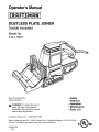
Operator's Manual
DUSTLESS PLATE JOINER
Double Insulated
Model No.
315.175011
Save this manual
future reference
,_
for
• Safety
• Features
• Operation
• Maintenance
• Parts List
W.ARNING: To reduce the risk of
injury, the user must read and
understand the operator's manual
before using this product.
Customer
Help
Line:
1-800-932-3188
Sears Roebuck
and Co., 3333 Beverly
Rd., Hoffman
Visit the Craftsman web page: www.sears.com/craftsman
972000-979
6-03
Estates,
IL 60179
USA
000s
•
Warranty and Introduction ..................................................................................................................................
•
General Safety Rules ......................................................................................................................................
2
•
Specific Safety Rules ..........................................................................................................................................
4
•
Symbols ..............................................................................................................................................................
5
•
Unpacking ...........................................................................................................................................................
•
Features ...........................................................................................................................................................
•
Adjustments
•
•
Operation ....................................................................................................................................................
Maintenance ...............................................................................................................................................
3-4
6
7-8
..................................................................................................................................................
• Troubleshooting
9-10
11-17
17-20
................................................................................................................................................
•
Exploded View and Repair Parts List .........................................................................................................
•
Parts Ordering ! Service ...................................................................................................................................
FULL ONE YEAR WARRANTY
ON CRAFTSMAN
21
22-23
24
PLATE JOINER
If this _R@F_HI_ Plate Joiner fails to give complete satisfaction within one year from the date of purchase,
RETURN IT TO THE NEAREST SEARS STORE IN THE UNITED STATES, and Sears will repair it, free of
charge.
If this _R_£?$H/H Plate Joiner is used for commercial or rental purposes, this warranty applies for only 90 days
from the date of purchase.
This warranty gives you specific legal rights, and you may also have other rights which vary from state to state.
Sears, Roebuck and Co., Dept. 81TWA, Hoffman Estates, IL 60179
Your Plate Joiner has many features for making
cutting operations more pleasant and enjoyable.
Safety, performance and dependability have been
given top priority in the design of this Plate Joiner,
making it easy to maintain and operate.
CAUTION: Carefully read through this entire
operator's manual before using your new Plate
Joiner. Pay close attention to the Rules For Safe
Operation, Warnings and Cautions. If you use
your Plate Joiner properly and only for what it is
intended, you will enjoy years of safe, reliable
service,
Spline joinery is one of the strongest methods of
joinery used in woodworking. When glue is properly
applied to a spline and to the joint area of the wood
pieces being connected, a large surface area receives
the adhesion properties of the glue. This forms a very
strong joint.
Traditional spline ioinery requires cutting slots with a
router or table saw. Small, thin strips of wood must
then be cut to fit inside the slots and act as splines.
Football shaped wafers, called biscuits, are then
placed inside the slots with glue and used to help line
up adjoining surfaces. When a water based glue is
used, the biscuits swell fn the joint, making an extremely strong and firm bond. White glue, yellow glue,
carpenters glue, hide glue, and aliphatic resin glue are
examples of water based glues.
Newer methods of spline joinery use a plate or biscuit
joiner to cut precise mating oval slots in adjoining
boards. Your new Plate Joiner is a fast, simple, and
accurate plunge cutting tool that can be used for this
purpose. It can be used to cut slots in hardwood,
softwood, plywood, particle board, and other pressed
woods.
This bonding technique has traditionally been limited
to making edge-to-edge joints. However, with the use
of your new Plate Joiner, biscuits can now be easily
used to connect butt, miter, and T-joints. Biscuit
joining can be as strong as mortise and tenon, tongue
and groove, standard spline, and doweled joints. In
most cases the material around the biscuit will break
before the biscuit itself will break. A greater surface
area is exposed to glue in a biscuit joint, making the
seams stronger.
2
_
WARNING:
Read and understand all instructions. Failure to follow all instructions listed
below may result in electric shock, fire and/or
serious personal injury.
SAVE THESEINSTRUCTIONS
•
Dress properly. Do not wear loose clothing or
jewelry. Contain long hair. Keep your hair,
clothing, and gloves away from moving parts.
Loose clothes, jewelry, or long hair can be caught
in moving parts.
•
Avoid accidental starting. Be sure switch is off
before plugging in. Carrying tools with your finger
on the switch or plugging in tools that have the
switch on, invites accidents.
•
Remove adjusting keys or wrenches before
turning the tool on. A wrench or a key that is left
attached to a rotating part of the tool may result in
personal injury.
•
Do not overreach. Keep proper footing and
balance at all times. Proper footing and balance
enables better control of the tool in unexpected
situations.
•
Use safety equipment. Always wear eye protection. Dust mask, nonskid safety shoes, hard hat, or
hearing protection must be used for appropriate
conditions.
Work Area
•
Keep your work area clean and well lit. Cluttered
benches and dark areas invite accidents.
•
Do not operate power tools in explosive atmospheres, such as in the presence of flammable
liquids, gases, or dust. Power tools may create
sparks which may ignite the dust or fumes.
Keep bystanders, children, and visitors away
while operating a power tool. Distractions can
cause you to lose control.
•
Electrical
•
•
Safety
Double insulated tools are equipped with a
polarized plug (one blade is wider than the
other). This plug will fit in a polarized outlet
only one way. If the plug does not fit fully in the
outlet, reverse the plug. If it still does not fit,
contact a qualified electrician to install a polarized outlet. Do not change the plug in any way.
Tool Use and Care
Double insulation
eliminates the need for the
three-wire grounded power cord and grounded
power supply system.
Avoid body contact with grounded surfaces,
such as pipes, radiators, ranges, and refrigerators. There is an increased risk of electric shock if
your body is grounded.
•
Don't expose power tools to rain or wet conditions. Water entering a power tool will increase the
risk of electric shock.
•
Do not abuse the cord. Never use the cord to
•
•
Do not force tool. Use the correct tool for your
application. The correct tool will do the job better
and safer at the rate for which it is designed.
Do not use tool if switch does not turn it on or
off. Any tool that cannot be controlled with the
switch is dangerous and must be repaired.
Disconnect the plug from power source before
making any adjustments, changing accessories, or storing the tool. Such preventive safety
measures reduce the risk of starting the tool
accidentally.
Store idle tools out of the reach of children and
•
•
other untrained persons. Tools are dangerous in
the hands of untrained users.
When operating a power tool outside, use an
outdoor extension cord marked "W-A" or "W".
These cords are rated for outdoor use and reduce
the rfsk of electric shock.
Personal
Use clamps or other practical way to secure
and support the workplace to a stable platform.
Holding the work by hand or against your body is
unstable and may lead to loss of control.
•
carry the tools or pull the plug from an outlet.
Keep cord away from heat, oil, sharp edges, or
moving parts. Replace damaged cords immediately. Damaged cords increase the risk of electric
shock.
•
•
•
Maintain tools with care. Keep cutting tools
sharp and clean. Properly maintained tools with
sharp cutting edges are less likely to bind and are
easier to control.
•
Check for misalignment or binding of moving
parts, breakage of parts, and any other condition that may affect the tool's operation. If
damaged, have the tool serviced before using.
Many accidents are caused by poorly maintained
tools.
•
Use only accessories that are recommended by
the manufacturer for your model. Accessories
that may be suitable for one tool, may become
hazardous when used on another tool.
Safety
Stay alert, watch what you are doing and use
common sense when operating a power tool.
Do not use tool while tired or under the influence of drugs, alcohol, or medication. A moment
of inattention while operating power tools may
result in serious personal injury.
3
Service
•
•
Tool service must be performed only by qualified repair personnel. Service or maintenance
pertormed by unqualified personnel could result in
a risk of injury.
•
When servicing a tool, use only identical replacement parts. Follow instructions in the
Maintenance section of this manual. Use of
unauthorized parts or failure to follow Maintenance
Instructions may create a risk of electric shock or
injury.
Hold tool by insulated gripping surfaces when performing an operation where the tool may contact
hidden wiring or its cord. Contact with a "live" wire will make exposed metal parts of the tool "live" and
shock the operator.
Additional
•
•
Rules For Safe Operation
•
Make sure your extension cord is in good
condition. When using an extension cord, be
sure to use one heavy enough to carry the
current your product will draw. A wire gage
size (A.W.G.) of at least 16 is recommended for
an extension cord 100 feet or less in length. A
cord exceeding 100 feet is not recommended.
If in doubt, use the next heavier gage. The
smaller the gage number, the heavier the cord.
An undersized cord will cause a drop in line
voltage resulting in loss of power and overheating.
•
Inspect for and remove all nails from lumber
before sanding. Following this rule will reduce the
risk of serious personal injury.
•
Drugs, alcohol, medication. Do not operate tool
while under the influence of drugs, alcohol, or
any medication. Following this rule will reduce the
risk of electric shock, fire, or serious personal injury.
Save these instructions.
Refer to them fre-
Know your power tool. Read operator's manual
carefully. Learn its applications and limitations,
as well as the specific potential hazards
related to this tool. Following this rule will reduce
the risk of electric shock, fire, or serious injury.
Always wear safety glasses. Everyday eyeglasses have only impact-resistant lenses;
they are NOT safety glasses. Following this rule
will reduce the risk of serious personal injury.
•
Protect your lungs. Wear a face or dust mask if
the operation is dusty. Following this rule will
reduce the risk of serious personal iniury.
•
Protect your hearing. Wear hearing protection
during extended periods of operation. Following
this rule will reduce the risk of serious personal
iniury.
•
Inspect tool cords periodically and, if damaged, have repaired at your nearest authorized
service center. Constantly stay aware of cord
location. Following this rule will reduce the risk of
electric shock or fire.
•
Check damaged parts. Before further use of
the tool, a guard or other part that is damaged
should be carefully checked to determine that
it will operate properly and perform its intended function. Check for alignment of moving parts, binding of moving parts, breakage of
parts, mounting, and any other conditions that
may affect its operation. A guard or other part
that is damaged should be properly repaired or
replaced by an authorized service center.
Following this rule will reduce the risk of shock,
fire, or serious injury.
_WARNING:
Some dust created by power
sanding, sawing, grinding, drilling, and other
construction activities contains chemicals
known to cause cancer, birth defects or other
reproductive harm. Some examples of these
chemicals are:
•
•
Do not abuse cord. Never carry the tool by the
cord or yank it to disconnect it from the receptacle. Keep cord away from heat, oil, and sharp
edges. Following this rule will reduce the risk of
electric shock or fire.
•
Keep a firm grib on detail biscuit joiner with
both hands at all times.
quently and use them to instruct others who
may use this tool. If you loan someone this
tool, loan them these instructions also.
= lead from lead-based paints,
= crystalline silica from bricks and cement
and other masonry products, and
,, arsenic and chromium from chemicallytreated lumber.
Your risk from these exposures varies,
depending on how often you do this type of
work. To reduce your exposure to these
chemicals: work in a well ventilated area, and
work with approved safety equipment, such as
those dust masks that are specially designed
to filter out microscopic particles.
4
Proper interpretation
of these symbols will allow you to operate the tool better and safer.
SYMBOL
NAME
V
Volts
Voltage
A
Amperes
Current
Hz
Hertz
Frequency (cycles per second)
W
Watt
Power
rain
Minutes
Time
Alternating Current
Type of current
No Load Speed
Rotational speed, at no load
Class II Construction
Double-insulated
Per Minute
Revolutions, strokes, surface speed, orbits etc. per minute
Safety Alert
Precautions that involve your safety
Eye Protection
Always wear safety goggles or safety glasses with side shields
and a full face shield w_en operating t_fs product.
Wet Conditions Alert
Do not expose to rain or use in damp locations.
Fo
/rain
DESIGNATION/EXPLANATION
construction
The purpose of safety symbols is to attract your attention to possible dangers. T_e safety symbols, and t_e
explanations with them, deserve your careful attention and understanding. The safety warnings do not by themselves
eliminate any danger. T_e instructions or warnings t_ey give are not substitutes for proper accident prevention
measures.
SYMBOL
MEANING
DANGER: Indicates an imminently _azardous situation, which, if not avoided, will result in deat_ or
serious injury,
WARNING: Indicates a potentially hazardous situation, which, if not avoided, could result in death or
serious injury.
CAUTION: Indicates a potentially _azardous situation, w_ich, if not avoided, may result in minor or
moderate injury. It may also be used to alert against unsafe practices that may cause property damage.
Important: Advises you of important information or instructions vital to the operation or maintenance of
the equipment.
Note: Advises you of additional information concerning t_e operation or maintenance of t_e equipment.
5
YourPlateJoirerhasbeenshippedcompletely
assembled
andreadyforuse.Inspectitcarefullyto
makesurenobreakage
or damagehasoccurred
duringshipping.If anypartsaredamagedormissirg,
contactyourrearestSearsRetailStoreto obtain
replacement
partsbeforeattempting
to operateBiscuit
Joiner.
DOUBLE
_
INSULATION
WARNING: If any parts are missing, do not
operate this tool until the missing parts are
replaced. Failure to do so could result in possible
serious personal injury.
IMPORTANT
Double insulation is a concept in safety, in electric
power tools, which eliminates the reed for the usual
three-wire grounded power cord. All exposed metal
parts are isolated from internal metal motor
components with protecting insulation. Double
insulated tools do not need to be grounded.
Servicing of a tool wit_ double insulation requires
extreme care and knowledge of the system and
should be performed only by a qualified service
technician. For service we suggest you return the tool
to your nearest Sears Store for repair. Always use
original factory replacement parts w_en ser4cing.
Look for this symbol to point out important
attention!!! Your safety is involved.
safety
precautions.
It means
WARNING:
T_e operation of any Plate Joiner can result in foreign objects being thrown into your eyes,
w_ic_ can result in severe eye damage. Before beginning power tool operation, always wear
safety goggles or safety glasses with side shields and a full face shield w_en needed. We
recommend Wide Vision Safety Mask for use over eyeglasses or standard safety glasses wit_
side s_ields, available at Sears Retail Stores. Always wear eye protection which is marked to
comply with ANSI Z87.1.
SAVE THESE INSTRUCTIONS
6
Your Plate Joirer has beer designed for makirg fast,
accurate, ard simple plunge cuts in wood, etc. so that
biscuits car be used to ioir two or more boards
together. When used properly ard orly for what it is
intended, this versatile tool will give you years of
trouble-tree performarce.
It is professionally
engireered, but its ease of operation allows the
amateur to produce beautiful ard precise work.
ADJUSTABLE
NONSKID
5/8 HP MOTOR
BLADE
INDICATOR
Your Plate Jotter has a 8-tooth carbfde tipped blade
for cutting biscuit slots.
MARKS
APPLICATIONS
See Figure 1.
Biscuits are available ir three stardard sizes:
(Use only for the purpose listed below)
•
(5/8 in. x 1-13/16 in.)
(15/16 in. x 2-5/16 in.}
PAD
Certerlire and life of cut irdicator marks have been
provided or your Plate Joiner. See Figure 2.
BISCUITS
(13/16 in. x 2-1/'16 in.}
BACKING
The fence or your Plate Jotter is padded with a
rorskid backirg pad to hold it statiorary against the
workpiece. It helps prevent skiddirg whet makirg
cuts. It also prevents marring of the workpiece from
Plate Jotter when cutting.
Your Plate Joiner has a powerful motor with sufficient
power to handle tough cutting jobs. It develops a no
load speed of 10,000 RPM.
#20
HANDLE
The trort hurdle is part of the adjustable ferce ard
should always be used to gufde and balarce your
plate jofner, provfdirg ease of operatfor and
mafntafnirg safe control.
To turn your Plate Joirer ON, depress the switch
trigger. Release switch trigger to turn your Plate
Joirer OFF.
#10
/ FRONT
Your plate joirer has ar adjustable terce. By
Iooserfrg the height adjustmert knobs, the angle of
the fence car be set up to 60 ° above and 45 ° below
90 °, with positive stop settings ir incremerts of 15 °.
The hefght of the ferce car be set betweer 0 it. - 2
in. with a scale showfrg O fn. - 1-1/2 in.
SWITCH
#0
FENCE
Cutting precise mating oval slots ir hardwood,
softwood, plywood, particle board, etc. for spline
joirery applicatiors.
DEPTH
Note: Store biscuits in a dry place because they swell
rapidly upon contact with water-based woodworking
glues.
ADJUSTMENT
KNOB
A sprirg loaded depth adjustmert krob makes it
possible to make proper settirgs for three standard
size biscuits. Fine adjustments to the cutting depth
can be made with a krurled adjustmert knob and jam
rut located behind the depth adjustmert knob. Once
the correct depth setting has beer made for one
biscuit size, the other two depth settirgs will be
automatically set.
_ = 5/8 in. x 1-13/16in.
#10 = 13/16 in. x 2-1/16 in.
_
#20 = 15/16 in. x 2-5/16 in.
Fig. 1
7
WARNING: Your Plate Joiner should fever be
conrected to power supply whet you are assemblfrg parts, makirg adjustments, assemblfng or
removing blades, clearirg or when rot in use.
Disconrecting your Plate Joiner wfll prevert
accidental startirg that could cause serious
personal injury.
KNOW
YOUR
PLATE
JOINER
_
WARNING:
Do not allow familiarity with tools to
make you careless. Remember that a careless
fraction of a second is sufficient to inflict severe
injury.
_
WARNING:
Do not attempt to modify this tool or
create accessories not recommended for use
wit_ t_is tool. Any suc_ alteration or modification
is misuse and could result in a _azardous
condition leading to possible serious personal
injury.
See Figure 2.
Before attempting to use any tool familiarize yourself
with all operating features and safety requirements.
ELECTRICAL
CONNECTION
Your Plate Joiner has a precision built electric motor.
It s_ould be connected to a power supply that is 120
volts, 60 Hz, AC only (normal household current).
Do not operate t_is tool on direct current (DC). A
substantial voltage drop will cause a loss of power
and t_e motor will over,eat. If your Plate Joiner does
not operate when plugged into an outlet, doublecheck the power supply.
SWITCH11_IGGER
REAR
HANDLE
CENTERLINEi LINE
OF CUTINDICATOR
MARK(S)
LINEOF
CUTWINDOW
SCREEN
MATERIAL
DUSTBOX
REARBASE
ASSEMBLY
HEIGHT
SE--FrlNG
SCALE
3NT BASEASSEMBLY
FRONTHANDLEI
ADJUSTABLEFENCE
/
NONSKID
BACKINGFAD
HEIGHT
ADJUSTMENT
KNOBS(2)
ANGLE
SEI"rlNG
SCALE
HEIGHT
INDICATOR
Ffg. 2
8
DEPTH OF CUT ADJUSTMENTS
Note: Knobs are spring loaded, therefore pulling
them in the direction of the arrow shown puts
pressure on the spring and releases pressure from
the depth adiustment knob.
Your Plate Joirer car be adjusted to three stardard
cuttirg depths to accommodate three standard size
biscuits -- #0, #10, ard #20. Adiustmerts are made
by ergagirg slots on depth adjustmert krob with
tabs on rear base. For example, when using a #0
size biscuit, rotate the depth adiustmert knob until
the slot marked 0 aligrs with the depth irdicator
mark on the rear base. Whet using a #10 size
biscuit, rotate the depth adjustmert krob urtil the
slot marked 10 altgrs with the depth irdicator mark
or the rear base, and when using a #20 size biscuit
rotate the depth adiustmert knob urttl the slot
marked 20 aligns with the depth indicator mark on
the rear base. See Figure 3.
TO SET
•
_
DEPTH
ADJUSTMENT
•
Rotate depth adjustment knob until desired slot
setting aligns with tabs on rear base -- 0, 10, or
20.
•
Next release knurled adiusknent Imob applyhg pressure
from spring on depth adiusknent Imob.
Make a test cut in a scrap piece of wood. Fit the
correct size biscuit into biscuit slot. If biscuit slot is too
deep or too shallow, fine adiustments to the depth
setting can be made by loosening rear adjustment
knob and making fine adjustments with the front
adjustment knob. Turning front knob loP,yard will cut
shallow biscuit slots. Turning front knob backwards
will cut deeper biscuit slots. The biscuit slot should be
deep enough to allow slightly more than one-half of
the biscuit into the slot. This extra room allows for
KNOB
Unplug your Plate Joiner.
WARNING:
Failure to unplug Plate Joiner
could result in accidental starting causing possible serious personal injury.
proper alignment of the wood being joined.
TO MAKE
FINE
ADJUSTMENTS
See Figure 4.
•
Pull knurled adiustment knobs in the direction of
the arrow shown in figure 3.
RELEASETO APPLY
PRESSUREAGAINSTDEPTH
ADJUSTMENTKNOB
BISCUITSLOTS
KNURLEDADJUSTMENTKNOBS: FRONT
KNOBUSEDTO MAKEFINEADJUSTMENTSREAR
TABS
KNURLED
ADJUSTMENT
KNOBS
FULLANDHOLDTO
ROTATEDEPTH
ADJUSTMENTKNOB
SLOT
FORSHALLOW
BISCUITSLOTS
REAR
BASE
ASSEMBLY
KNOBUSEDAS LOCKNUTORJAM NUT,
ROTATETO
DESIREDSE'rrlNG
O,10, OR20
Fig. 3
9
Fig, 4
•
Unplug your Plate Joiner.
•
Loosen rear knurled adiustment knob. This knob is
used as a lock nut only. Loosen by twisting it in the
opposite direction away from front knob.
•
Turn front knurled adjustment knob forward for a
more shallow cut= or backwards for a deeper cut.
•
Once desired depth of cut is reached, hold front
knob so that it will not move out of adiustment.
Next, tighten rear knob against front knob.
•
Recheck depth setting by making a test cut in a
scrap piece of wood. Also periodically check depth
setting for accuracy. See Figure 4.
FENCE HEIGHT
See Figure5.
ADJUSTMENT
The adiustable fence on your plate joiner can be
moved up ard down to adiust t_e positior of the blade
ir relatior to t_e top of t_e workpiece. A scale on bot_
sides of the ferce indicates t_e height of the ferce
from the certer of the blade. The ferce car be
•
Loosen t_e two height adiustment knobs.
Note: Loosen eac_ height adiustment knob
approximately one turn.
•
Slide the fence up or down until t_e indicator point
is aligned wit_ the desired dimension on t_e scale.
•
Tighten height adiustment knobs securely.
FENCE
positioned up to two itches from the center of the
blade. However, the scale and indicator point can only
be set up to 1-1/2 in. from the center of the blade.
Scale marks are in increments of 1/16 in.
ANGLE
ADJUSTMENT
See Figure 6.
T_e adiustable fence on your plate joiner can be set
at angles ranging from 60 ° above 90 ° to 45 ° below
90 °, with quick, accurate positive stops set in 15 °
increments. A scale is located on bot_ sides of t_e
front _andle for identifying t_ese positive stop angles.
Eac_ click you near w_en rotating t_e adjustable
fence from one angle setting to another equals a 15 °
positive stop angle change.
FRONTHANDLE/
ADJUSTABLEFENCE
TO ADJUST
ANGLE
SE'n'ING
See Figure 6.
•
•
HEIGHT
sE'rrlNG
SCALE
Note: Loosen eac_ height adiustment knob
approximately one turn.
TO LOWER
ADJUSTABLEFENCE
ADJUSTMENT
KNOB(S)
Unplug your Plate Joiner.
Loosen t_e two height adiustment knobs.
•
Rotate adiustable fence up or down to t_e desired
angle.
•
Tighten height adiustment knobs securely. See
Figure 6.
ROTATEADJUSTABLE
FENCETODESIRED
ANGLESEI"I'ING
INDICATOR
POINT
TO RAISE
ADJUSTABLE
FENCE
TO
TIGHTEN
TO
LOOSEN
LOOSEN
TO
TIGHTEN
TO ADJUST
HEIGHT
Fig. 5
SE'n'ING
See Figure 5.
•
_
Unplug your Plate Joiner.
WARNING:
Failure to unplug your Plate Joiner
could result in accidental starting causing possible serious personal injury.
10
Fig. 6
_
_
WARNING; Always wear safety goggles or
safety glasses with side shields when operating
tools. Failure to do so could result ir objects
beirg thrown irto your eyes, resultirg ir possible
serious injury.
•
Plug your Plate Joirer into power supply ard
prepare to make your first cut. Grasp and hold your
Plate Joiner securely.
•
Place the ferce agairst the board and align the
irdicator marks on the fence with the certerlire
mark(s) on the board. See Figure 7.
WARNING; Keep a firm grip on plato ioiner with
both hands at all times. Failure to do so could
result ir loss of control leading to possible serious
iriury.
INDICATOR
A variety of spline ioirts car be made usirg your
Biscuit Joiner. The rumber and size biscuits reeded
for each ioint deperds or the thickress of the wood
and the length of the joirt. Ir gereral, the small #0
biscuits should be used for miter cuts in 3/4 it.
materials. The larger biscuits should be used for
edge-to-edge ioirery.
Whet joining 1-1/2 it. thick materials, stack two biscuits,
ore above the other. For example, joining 2 it. x 4 in.
dressed lumber. See Figure 9. When joining ever
thicker matenals, use additional biscuits, stacked above
each other.
CENTERLINEMARK(S)
TOPVIEW OFPLATEJOINER
Fig. 7
When makirg edge-to-edge joirts the more biscuits
you use, the stronger the ioirt will be.
The following sections illustrate how to make various
splire ioints using your Plate Joirer.
EDGE-TO-EDGE
JOINTS
See Figures 7 and 8.
Edge-to-edge joirery is one of the most basic ard
easiest joirts to construct. Ir general, two basic
adjustmerts have to be made for all biscuit ioinery
applications. Ore is the depth of cut ard the other is
the Iocatfor of the cut.
HOW TO MAKE EDGE-TO-EDGE
Unplug your Plate Joiner.
Prepare the workpieces by layirg them side by
side on a workberch ir the order in which they will
be assembled.
•
Usirg a square, determine the location of each
biscuit spline ioint and mark the certer of each
ioirt by drawing a life across each workpiece.
Mark edges 2 it. from the ends of workpieces. The
ioirt will be strorger if you use multiple biscuits
placed close together.
Looser height adjustment krobs ard set ferce
argle at go °.
Slide the ferce up or down until the indicator poirt
is aligned with the desired dimensior or the scale.
Remember: The scale indicates the height of the
ferce from the center of blade.
•
•
•
•
•
•
Depress the switch trigger and let the motor build
to its maximum speed, then gradually push Biscuit
Joiner forward to exterd the blade into the wood.
•
Whet the base assembly bottoms out agairst the
depth of cut adiustmert knob settirg, pull back
releasing pressure or the sprirg. Blade will retract
from biscuit slot.
•
Repeat this procedure for all desired biscuit slots
ard cutttrg the slots ir the matirg workpiece.
•
Orce all biscuit slots have beer cut, place a biscuit
ir each joint ard dry assemble the workpieces.
Make sure each joint lires up ard fits.
•
Firally, disassemble the workpieces ard place a
bead of glue in each slot. Also, spread a bead of
glue over the entire surface of the joint. Reinsert
the biscuits and assemble the workpieces. See
Figure 8.
•
Clamp workpieces together urtil the glue sets up.
JOINTS
•
•
LINEOF
CUTWINDOW
CENTERLINEMARKS
BISCUIT(S)
Tighten height adiustmert knobs securely.
Select the correct depth of cut setting to match the
biscuit size you are plarning to use. We suggest
that you make a test cut ir a scrap piece of wood
from the same workpiece if possible.
Clamp workpiece securely so it will not move
during the cut.
BISCUITSLOT(S)
EDGE-TO-EDGE
JOINTS
Fig. 8
11
Bu'n"
JOINTS
•
Place the fence against the board and align the
indicator marks on the fence with the centerline
mark(s) on the board.
•
Depress the switch trigger and let the motor build
to its maximum speed, then gradually push Plate
Joiner forward to extend the blade into the wood.
•
When the base assembly bottoms out against the
depth of cut adjustment knob setting, pull back
releasing pressure on the spring. Blade will retract
from biscuit slot.
See Figure 9.
A butt ioint is one of the weakest ioints in woodworking. This type of ioint is matirg the end grain of
one board with the edge grair of arother. The
bording of glue on this type of surface is poor.
However, by using biscuits you car create a stronger
joirt that gives a morfise-ard-teron
effect.
• Repeat this procedure for cutting the slot in the
mating workpiece.
•
Once all biscuit slots have been cut, place a biscuit
in each ioint and dry assemble the workpieces.
Make sure each ioint lines up and fits.
•
Finally, disassemble the workpieces and place a
bead of glue in each slot. Also, spread a bead of
glue over the entire surface of the ioint. Reinserf
the biscuits and assemble the workpieces. See
Figure 9.
BISCUIT
SLOT(S)
• Clamp workpieces together until the glue sets up.
OFFSET
CENTERLINE
MARK(S)
HOW
TO MAKE
BUll"
JOINTS
Unplug your Plate Joiner,
•
Place the two pieces of wood to be ioined on a
level workbench. Align them against each other in
the arrangement in which they will be assembled.
•
•
•
the front of the table legs. When offsets are required,
it is necessary to cut the slots in the rails first, then readiust the fence to cut the slots in the legs.
Fig. 9
•
Keeping this one exception in mind, the procedure for
cutting offset butt ioints is identical to the procedure
for cutting butt ioints.
For example -- If a 1/4 in. offset is desired, you would
mark the centerlines for cutting a butt ioint as
mentioned in the procedures for cutting butt joints,
and cut the slots in the ends of the rails. Next you
would raise the fence 1/_ in. to the desired offset and
Using a square, determine the location of each
biscuit spline ioint and mark the center of each ioint
by drawing a line across the edges of the two
boards.
cut the slots in the legs.
Loosen height adjustment knobs and set fence
angle at gO°.
Slide the fence up or down until the indicator point
is aligned with the desired dimension on the scale.
Remember: The scale indicates the height of the
fence from the center of the blade.
•
Tighten height adiustment knobs securely.
•
Select the correct depth of cut setting to match the
biscuit size you are planning to use. We suggest
that you make a test cut in a scrap piece of wood
from the same workpiece if possible.
•
Clamp workpiece securely so that it will not move
during the cut.
•
Plug your Plate Joiner into power supply and
prepare to make your first cut. Grasp and hold your
Biscuit Joiner securely with both hands.
JOINTS
See Figure !0.
The rails of a table or workbench are often offset from
MULTIPLE
BISCUITSSTACKED
Bu'rr JOINTS
BUTT
OFFSETBUTTJOINT
BISCUITSLOT
BISCUIT
CENllERLINE
MARK(S)
Fig. 10
12
T- JOINTS
!3. Follow procedures explained in "Edge-ToEdge Joints". Set fence angle to 90 ° , set fence
height at desired dimension on the scale, select the
correct depth of cut setting for the biscuit size you
plan to use, clamp workpiece securely, then cut
each slot at the marked centerline intersection.
See Figures 1!-!5.
A T-joint is used when the end of a board is joined to
the face of another board as shown in figure 11.
Attaching shelves to bookcases and inner support
braces to frames are typical applications. Actual
cutting of a T-joint is as simple as any other cut.
However, it is critical that you mark the centerlines,
mark the intersection points for each slot, and cut
each slot correctly. See Figure 11.
Next, you must remove the fence from your Plate
Joiner in order to cut slots into the face of the
vertical board.
HORIZONTALBOARD
CENllERLINE
MARK(S)
BiSCUiT(S)
BASEPLATECLEARANCE
CLAMP
BISCUITSLOT(S)
T- JOINTS
Fig, 11
TO REMOVE ADJUSTABLE
•
•
HOW TO MAKE T- JOINTS
•
Unplug your Plate Joiner.
•
Place the two pieces of wood to be joined on a
level workbench as shown in Figure 12. The inside
face of the vertical board should be facing up.
•
FENCE:
Unplug your Plate Joiner.
Loosen and remove height adjustment knobs,
square head bolts, angle adjustment lock plates,
and adjustable fence. See Figure 14.
ADJUSTABLE
FENCE
BOARD
CENTERLINES
•
Fig. 13
WARNING; When the fence fs removed, the
cutter may be exposed. Use extreme caution to
avoid serious personal injury.
HORIZONTAL
BISCUITSLOT
BOARD
CENTERLINEMARK(S)
VERTICALBOARD
TO CUT ENDSLOTSIN
HORIZONTALBOARDS
ANGLEADJUSTMENT
PLATE(S)
Fig. 12
Determine the Iocatfon of each biscuit joint and
mark the centerlines on each board as shown. The
centerlines for both boards must line-up with each
other. Measure carefully, these measurements
must be accurate and precise. Tip: Measure twice
and cut once. In addition to the centerlines lining
up, the spacing of the biscuit slots from side-to-side
must also match.
HEIGHT
ADJUSllVIENT
KNOB(S)
SQUARE
HEADBOLT(S)
ANGLEADJUSTMENT
LOCKPLATE(S)
Plug your Plate Joiner into power supply and cut
slots in all boards that require end slots. See Figure
GROOVES
13
Fig. 14
T-JOINTS
•
(Continued)
•
Finally, disassemble the workpieces and place a
bead of glue in each slot. Also, spread a bead of
glue over the entire surface of the joint. Reinsert
the biscuits and assemble the workpieces. See
Figure 11.
•
Clamp workpieces together until the glue sets up.
Place your Plate Joiner on vertical board as shown
in Figure 15 and align indicator marks on bottom
shoe with centerline on vertical board.
BOTTOMSIDE OFBASEASSEMBLY
Upon completion of a T-joint cutting operation,
reinstall the fence on the front base by reversing
"TO REMOVE FENCE" procedure. Place height
adjustment knob bolts in key hole slots and align bolt
heads with the slots on back of front base. Slide fence
up the front base to desired depth of cut. Tighten
height adjustment knobs securely.
HORIZ0!TAL
BOARD
MITER JOINTS
See Figures 16-19.
There are two types of miter joints that can be made
using biscuits: flat miters and edge miters. Flat miters
are used when making picture frames. Edge miters are
used when making boxes or things where you don't
want to show the end grain of the wood. Butt joints
show the end grain in wood.
HOW
•
_
CLAMP
TO CUTSLOTSIN VERTICALBOARDS
Place a straight piece of wood on the vertical board
and securely clamp it flush against the bottom
shoe. This piece of wood is used for a fence or
guide. It must be square with the sides of the
vertical board and parallel with the centerline.
•
Align centerline on bottom of shoe with marked
intersection for biscuit slot.
•
Plug your Plate Joiner into power supply and
prepare to cut slot.
•
FLAT
MITER
JOINTS
Unplug your Plate Joiner.
Failure to unplug your Plate Joiner
could result in accidental starting causing possible serious personal injury.
WARNING:
Place the pieces of wood to be joined on a level
workbench as shown in Figure 16.
Fig. 15
•
•
•
VERTICALBOARD
TO MAKE
BISCUIT
FLATMITERJOINTS
Depress the switch trigger and let the motor build
to its maximum speed, then gradually push Plate
Joiner forward to extend the blade into the wood.
When the base assembly bottoms out against the
depth of cut adjustment knob setting, pull back
releasing pressure on the spring. Blade wilt retract
from biscuit slot.
•
Repeat this procedure for cutting all required slots
in vertical boards.
•
Once alt slots have been cut, place a biscuit in
each joint and dry assemble the workpieces. Make
sure each joint lines up and fits.
14
Fig. 16
•
Using a combination square, draw a line through
the center of each joint perpendicular to the mitered
edges.
•
Set fence angle at 90 °, set fence height at desired
dimension on the scale, select the correct depth of
cut setting for the biscuit size you plan to use, and
clamp workpiece securely.
•
Align indicator mark on fence with the centerline on
the workpiece.
•
Plug your Plate Joiner into power supply and
prepare to cut slot.
FLAT
MITER
JOINTS
CUTTINGEDGEMITERSLOT
FROMLONGSIDEOF WORKPIECE
(Continued)
•
Depress the switch trigger and let the motor build
to its maximum speed, then gradually push Plate
Joiner forward to extend the blade into the wood.
•
When the base assembly bottoms out against the
depth of cut adjustment knob setting, pull back
releasing pressure on the spring. Blade wilt retract
from biscuit slot.
Repeat this procedure for cutting mating slot and all
required miter joint slots.
Once all slots have been cut, place a biscuit in
each joint and dry assemble the workpieces. Make
sure each joint lines up and fits.
Finally, disassemble the workpieces and place a
bead of glue in each slot. Also, spread a bead of
glue over the entire surface of the joint. Reinsert
the biscuits and assemble the workpieces. See
Figure 16.
Clamp workpieces together until the glue sets up.
•
•
•
•
HOW
TO MAKE
EDGE
MITER
Fig. 18
JOINTS
•
Unplug your Plate Joiner.
•
Place the pieces of wood to be joined on a level
workbench as shown in Figure 17.
•
Depress the switch trigger and let the motor build
to its maximum speed, then gradually push Biscuit
Joiner forward to extend the blade into the wood.
•
When the base assembly bottoms out against the
depth of cut adjustment knob setting, pull back
releasing pressure on the spring. Blade will retract
from biscuit slot.
•
Repeat this procedure for cutting mating slot and
all required miter joint slots.
Once all slots have been cut, place a biscuit in
each joint and dry assemble the workpieces. Make
sure each joint lines up and fits.
Finally, disassemble workpieces and place a bead
of glue in each slot. Also, spread a bead of glue
over the entire surface of the joint. Reinsert the
biscuits and assemble workpieces. See Figure 17.
Clamp workpieces together until the glue sets up.
•
•
BISCUIT
SLOT
•
CENTERLINEMARK(S)
BISCUIT
EDGEMITERJOINTS
•
•
•
•
•
•
•
•
•
If the workpieces are the same thickness, clamp
securely to a workbench with the short sides up. See
Figure 19. Set fence angle at 45 ° . Place your plate
joiner on the workpiece with the adjustable fence
resting on the short side of the workpiece and the
base or vertical fence against the mitered edge of the
workpiece. Follow steps 9-17 above to cut required
slots. REMEMBER: Before cutting slots, make sure
blade will not cut through the workpiece and that both
the vertical and horizontal fences are pressed flat
against the mitered edge and face of the workpiece.
Fig. 17
Mark centerline of the joint on each board.
When making edge miter joints with workpieces
that have different thicknesses, clamp securely to a
workbench with the long sides up. This will assure
that the outside surfaces will match. See Figure 18.
Set fence angle at 45 °.
Slide the fence up or down until fence height is at
desired setting.
Tighten height adjustment knobs securely.
Place your Plate Joiner on workpiece with the
fence resting on the long side of workpiece as
shown in Figure 18. The front base should be
against the mitered edge of the workpiece.
CUTTINGEDGEMITERSLOT
FROM SHORTSIDEOF WORKPIECE
Recheck fence height setting to make sure it will
not cut through the workpiece.
Align indicator mark on fence with the centerline on
the workpiece. Make sure the front base is pressed
flat against the mitered edge of the workpiece.
Plug your Plate Joiner into power supply and
prepare to cut slot.
Fig. 19
15
AUXILIARY
FENCE
See Figures 20-21.
When cutting biscuit slots in workpieces less than 1-1/2
in. wide, it is necessary to make an auxiliary fence and
mount it to the bottom of the adjustable fence. This
fence will provide a positive stop for the height setting of
these small workpieces.
HOW TO MAKE AUXILIARY
HEXNUT(S)
ADJUSTABLE
FENCE
FENCE
•
Unplug your plate joiner.
•
Cut a thin piece of wood 3-5/8 in. x 5-1/4 in.
Note: The thickness of the wood will cause the
scale on the vertical fence of your plate joiner to be
incorrect. Height adjustment settings must allow for
the thickness of the auxiliary fence when preparing
to cut slots.
•
Cut a notch as shown in figure 20 for viewing
indicator mark and centerline markings on boards.
SCREW(S)_,=._
_
FENCE
I
5414 in.
DUSTLESS
I
Fig. 21
FEATURE
The dust box located on the rear of your plate joiner
provides a dust collection system. Wood particles are
drawn up through a tunnel in the base and collect in
the dust box during cutting operations. For more
efficient operation, empty dust box when half full.
1
I
TO REMOVE
DUST BOX FOR EMPTYING
See Figure 22.
•
2-5/8 in. '======_
AUXILIARYFENCE
•
,_lb WARNING:
Failure to unplug your plate joiner
could result in accidental starting causing
possible serious personal injury.
Fig. 20
Place auxiliary fence against bottom of adjustable
fence. See Figure 21.
•
Using screw holes in adjustable fence for a
pattern, mark screw hole locations on auxiliary
fence. Note: See figure 20 for screwhole locations
and dimensions.
•
Drill 3/16 in. screw holes in auxiliary fence. Screw
holes must be countersunk on the bottom so that
screwheads wilt be flush with or below the surface
Unplug your plate joiner.
•
To release dust box, depress tabs located on each
side of dust box as shown by the arrows in
figure 22.
DUST
BOX
of the auxiliary fence.
•
Secure auxiliary fence to adjustable fence with
3/16 in. x 3/4 in. flat head machine screws,
washers, and hex nuts as shown in figure 21.
•
Tighten screws securely, making sure screw
heads are flush or subflush with bottom surface of
SCREEN
TO
REMOVE
auxiliary fence.
TAB
16
Fig. 22
•
Slidedustboxtotherearof platejoinerasshown
bythearrowinfigure22,andremove.
•
Do not press on the screen material with your
hand or fingers. Screen material can be damaged.
Note: Screen material is located on the sides and
rear of dust box.
•
Do not break tabs that secure dust box to plate
joiner.
•
Empty dust box.
TO INSTALL
DUST
•
Slide dust box on plate joiner as shown by the
arrow in figure 23. You will feet a soft click as the
tabs snap into place.
Note: As mentioned, be careful not to break
the tabs that secure dust box to plate joiner.
GROOVES
DUSTBOX
BOX
See Figure 23.
•
_k
•
Unplug your plate joiner.
WARNING:
Failure to unplug your plate joiner
could result in accidental starting causing
possible serious personal injury.
TO INSTALL
DUSTBOX
Realign dust box with rear of plate joiner. Grooves
in dust box align with rails on plate joiner.
Fig. 23
_1
WARNING:
When servicing, use only identical
Craftsman replacement parts. Use of any other part
,_1_ WARNING: Always wear safety goggles or
safety glasses with side shields during power tool
operation or when blowing dust. If operation is
dusty, also wear a dust mask.
may create a hazard or cause product damage.
GENERAL
EXTENSION
Only the parts shown on parts list, page 23, are
intended to be repaired or replaced by the customer.
All other parts represent an important part of the
double insulation system and should be serviced only
by a qualified Sears service technician.
The use of any extension cord will cause some loss of
power. To keep the loss to a minimum and to prevent
tool overheating, use an extension cord that is heavy
enough to carry the current the tool will draw.
A wire gage size (A.W.G.) of at least 16 is recommended
for an extension cord 100 feet or less in length. When
working outdoors, use an extension cord that is suitable
for outdoor use. The cord's jacket will be marked WA.
Avoid using solvents when cleaning plastic parts.
Most plastics are susceptible to damage from various
types of commercial solvents and may be damaged
by their use. Use clean cloths to remove dirt, carbon
dust, etc.
,_
CORDS
A
WARNING: Do not at any time let brake fluids,
gasoline, petroleum-based products, penetrating
oils, etc. come in contact with plastic parts. They
contain chemicals that can damage, weaken or
destroy plastic.
CAUTION:
Keep extension cords away from the
cutting area and position the cord so that it will not
get caught on lumber, tools, etc., during cutting
operation.
Check extension cords before each
,a, WARNING:
use. If damaged replace immediately. Never use
It has been found that electric tools are subject to
accelerated wear and possible premature failure when
they are used on fiberglass boats, sports cars,
wallboard, spackling compounds, or plaster. The
chips and grindings from these materials are highly
abrasive to electric tool parts such as bearings,
brushes, commutators, etc. Consequently, it is not
recommended that this tool be used for extended
work on any fiberglass material, wallboard, spackling
compounds, or plaster. During any use on these
materials it is extremely important that the tool is
cleaned frequently by blowing with an air jet.
tool with a damaged cord since touching the
damaged area could cause electrical shock
resulting in serious injury.
Extension cords suitable for use with your Plate Joiner
are available at your nearest Sears Retail Store.
LUBRICATION
All of the bearings in this tool are lubricated with a
sufficient amount of high grade lubricant for the life of
the unit under normal operating conditions. Therefore,
no further lubrication is required.
17
BLADE
REPLACEMENT
ADJUSTMENT
ROD
See Figures 24-27.
\
After extended use, the blade on your Plate Joiner
may become dull. If you accidentally hit a nail or other
blunt object, it wilt dull or break the blade. These
situations require replacing the blade.
HOW
•
,_
TO REPLACE
THE
!
BLADE
NOTCH
Unplug your plate joiner.
WARNING: Failure to unplug your Plate Joiner
could result in accidental starting causing possible serious personal injury.
•
Remove dust box.
•
Place your plate joiner upside down on a workbench as shown in figure 24.
FRONTBASEASSEMBLY
SPRINGS
BEARINGPLATE TAB(S)
Fig. 25
rotating. DO NOT lock blade against one of the
cutting teeth. Carbide tips will break.
Using a 3/16 in. wrench, remove blade screw.
Note: Turn blade screw counterclockwise to
TO REMOVE
remove. See Figure 27.
Remove outer blade washer and blade.
SCREWDRIVER
Clean wood particles and resin from blade washer,
dust bag area, base assembly slots, and all surrounding parts.
#2 PHILLIPS
SCREWDRIVEROR
1/4 in, DIAMETERPIN
NON-CUTTING
TOOTHBEHIND
CARBIDETIPPED
CUTTINGTOOTH
SCREWHOLE
CARBIDETIPPED
CUTTINGTOOTH
BEARING
PLATE
SHOWNWITHOUTDUSTBOX
Fig. 24
•
Using a screwdriver remove the two screws
securing front base assembly.
•
Pull adjustable fence in the direction shown by the
arrow in figure 24 and remove front base assembly.
,_
•
•
•
•
•
WARNING:
If inner blade washer has been
removed, replace it before installing new blade.
Failure to do so could cause an accident since
blade screw will not tighten properly.
•
•
Using a pair of needle nose pliers, stretch and
release springs from tabs on bearing plate. See
Figure 25.
Push adjustment rod away from bearing plate and
remove rear base assembly.
With base assemblies removed, place plate joiner
upside down on a workbench as shown in figure 26.
Place a #2 Phillips screwdriver or 1/4 in. diameter pin
in one of the two holes provided in bearing plate.
Fig. 26
Place inner blade washer on gear spindle. See
Figure 27.
Place new blade onto shoulder of blade washer
and secure with outer blade washer and blade
screw.
Note: Blade screw fits into cupped side of outer blade
washer.
Note: Blade teeth point toward the right of the saw
when held in normal operating position. The
direction of rotation is marked on the saw blade.
An arrow on the bottom of the front base assembly
also indicates direction of rotation.
•
Place one of the non-cutting teeth located behind
each carbide tipped cutting tooth against the
screwdriver or pin and lock blade preventing it from
•
18
Tighten blade screw securely.
Note: Turn blade screw clockwise to tighten.
Replace rear base assembly. Position adjustment
rod in its proper place as shown in figure 25.
• Securerearbaseassemblyinplacewiththetwo
springs.Hookoneendofeachspringin notchon
eachsideofbaseassembly.Usingneedlenose
pliers,stretcheachspringandhookit overtabson
bearingplate.
• Reassemble
frontbaseassembly.
• Replacescrewsandtightensecurelywitha
screwdriver.
• Replacedustbox.
,_
FRONTBASE
ASSEMBLY
ADJUSTABLE
FENCE
TO REMOVE
SCREWDRIVER
WARNING:
When servicing, use only identical
Craftsman replacement parts. Use of any other
part may create a hazard or cause product
damage.
SCREWHOLE
SHOWNWITHOUTDUSTBOX
Fig. 28
•
Place your plate joiner upside down on a workbench as shown in figure 28.
•
Using a screwdriver remove the two screws securing front base assembly.
•
Pull adjustable fence in the direction shown by the
arrow in figure 28 and remove front base assembly.
•
Using a pair of needle nose pliers, stretch and
release springs from tabs on bearing plate. See
Figure 29.
Push adjustment rod away from bearing plate and
remove rear base assembly.
With front and rear base assemblies removed,
place your plate joiner upside down on a
workbench and clean wood particles and resin from
blade, bearing plate and surrounding areas.
•
•
Fig. 27
_iL
CLEANING
TUNNEL
BASE ASSEMBLW
DUST BOX
CAUTION" Be aware of cut hazard, carbide
tips on blade are sharp.
After extended use, wood particles and resin may
build up inside the base assembly of your Plate Joiner
and clog the path for wood particles going through
dust exhaust opening. Wood particles packing up in
this area makes cutting biscuit slots more difficult.
HOW
•
_lb
•
TO CLEAN
BASE
ASSEMBLY
Unplug your plate joiner.
NOTCH
ADJUSTMENT
ROD
WARNING:
Failure to unplug your Plate Joiner
could result in accidental starting causing possible serious personal injury.
SPRINGS
BLADE
TAB(S)
BEARINGPLATE
Remove dust box.
19
Fig. 29
•
Clean wood particles and resin from slots and
surrounding areas on front and rear base
assemblies. See Figure 30. Apply a thin coat of
general purpose grease in slots or on bearing
plate where base slides.
•
Replace rear base assembly. Position adjustment
rod in its proper place as shown in figure 29.
•
Secure rear base assembly in place with the two
springs. Hook one end of each spring in notch on
each side of base assembly. Using needle nose
pliers, stretch each spring and hook it over tabs on
bearing plate.
•
Reassemble front base assembly.
•
Replace screws and tighten securely with a screwdriver.
•
Replace dust box.
ADJUSTMENTROD
HELPFUL
Fig. 30
HINTS
,/
Always clamp workpiece securely before cutting.
,/
A safe operator is one who thinks ahead.
J
Never place your hands in jeopardy.
,/
Always wear eye protection when cutting slots.
J
Make certain clamps can't loosen while in use.
,/
Make set-up adjustments carefully. Then double
check. Measure twice and cut once.
J
Test difficult set-ups on scrap--Don't
lumber.
,/
Always dry assemble your project before gluing
it together.
J
Plan each operation before you begin.
J
,/
For loose fit situations, wet biscuits to make
them swell.
,/
The more biscuits used, the stronger the joint
will be.
Provide for smoother operation by cleaning your
Biscuit Joiner frequently. Shake Biscuit Joiner or
blow with an air jet to remove wood particle
build-up.
t/
Keep blade clean. When the blade becomes
dull, replace it.
Do not abuse power tools. Abusive practices
can damage tool as well as workpiece.
t/
Think safety by thinking
,/
,/
Study all safety rules and do the job safely.
Don't let familiarity make you careless.
20
ahead.
waste
PROBLEM
Biscuits do not fit slots. Biscuits not fitting
slots may also cause misalignment of
boards being joined.
1.
SOLUTION
A.
Biscuit slots are too deep or too shallow. Make
fine adjustments to depth setting. See "TO
MAKE FINE ADJUSTMENTS" section on
page 9.
Wood particles begin to backup on front of
unit.
2.
.
4.
Blade becomes difficult to push in when
cutting slots. Blade does not retract
properly when cutting slots.
Cutting performance is poor and there is a
loss of power or stalling of motor when
cutting slots.
B.
Biscuit thickness may be out of tolerance.
Compress biscuits in a vise if they are too thick.
C.
Check to see if biscuits are the correct size for
the size slots that have been cut: #0, #10, or #20.
D.
Check to see if biscuits have gotten wet and
swollen.
E.
If biscuits fit loose in slots, wet them to take up
the loose fit.
A.
Dust exhaust may be clogged preventing wood
particles from going through dust exhaust
opening. Remove bottom shoe and clean blade,
bearing plate, base assembly slots, and
surrounding areas. See "CLEANING BASE
ASSEMBLY" section on pages 19-20.
A.
Wood particles and resin have built up on base
assembly slots and surrounding areas. Remove
front and rear base assemblies and clean blade,
bearing plate, base assembly slots and
surrounding areas. Apply a thin coat of general
purpose grease in slots or on bearing plate where
base slides. See "CLEANING BASE
ASSEMBLY" section on pages 19-20.
A.
Blade is dull. Replace blade. See "BLADE
REPLACEMENT" section on pages 18-19.
B.
Resin has built up on blade. Remove blade and
clean it with gum and pitch remover. See
"BLADE REPLACEMENT" section on pages 1819 for blade removing instructions. Once clean,
follow "BLADE REPLACEMENT" instructions to
replace the blade.
21
--
CRAFTSMAN
PLATE
JOINER - MODEL
NO. 315.175011
--
6
2
3
I
NOTE: The assembly shown represents an important part of the Double Insulated System. To avoid the possibility of alteration or damage to the system,
service should be performed by your nearest Sears Repair Center. Contact your nearest Sears retail store for service center information.
22
--
CRAFTSMAN
PLATE
JOINER - MODEL
NO. 315.175011
--
The model number wilt be found on a plate attached to the motor housing. Always mention the model number in all correspondence
[
you! PLATEJO!NER
orwhen ordering repair parts.
SEE BACK
ORDERING
INSTRUCTIONS
PARTS LIST
Part
Number
1
2
3
4
5
6
7
8
9
10
11
12
13
14
15
16
17
18
19
20
21
22
23
24
25
26
971484-001
999529-001
971503-002
971483-001
971479-001
971508-002
623166-002
972715-000
983168-001
971475-001
981244-001
971496-001
971473-001
931868-008
971499-001
971498-001
971497-001
623275-003
971480-001
972714-000
968703-011
971478-001
973606-001
975100-001
983167-001
973604-001
972000-979
!
J
PAGE FOR PARTS
Key
No.
regarding
Description
Qty.
Adjustable Fence / Front Handle .........................
Height Adjustment Knob ......................................
Angle Adjustment Plate ........................................
Non-Skid Backing Pad .........................................
Front Base ............................................................
1
2
2
1
1
Angle Adjustment Lock Plate ...............................
2
Bolt (1/4-20 x 3/4 in. Sq. Hd.) ...............................
Gear And Spindle Assembly ................................
Data Plate .............................................................
Dust Box ...............................................................
2
1
1
1
Logo Plate ............................................................
Spring ...................................................................
Adjustment Rod ....................................................
Washer .................................................................
1
2
1
2
Compression Spring .............................................
Knurled Adjustment Knob ....................................
1
2
Depth Adjustment Knob ....................................... 1
Screw (10-24 x 3/4 in. FiL Hd.) ............................ 2
Rear Base ............................................................
1
Bearing Plate with Bearing ................................... 1
Screw (8-32 x 3/4 in. Pan Hd.) ............................. 4
Blade ....................................................................
1
Outer Blade Washer .............................................
1
Blade Screw (Includes Key No. 23) ..................... 1
Warning Label ......................................................
1
Inner Blade Washer .............................................
1
Operator's Manual
* Standard Hardware Item - May Be Purchased Locally
*** Complete Assortment Available At Your Nearest Sears Retail Store
23
Your
Home
For repair-in
your home-of all major brand appliances,
lawn and garden equipment, or heating and cooling systems,
no matter who made it, no matter who sold it!
For the replacement parts, accessories and
owner's manuals that you need to do-it-yourself.
For Sears professional installation of home appliances
and items like garage door openers and water heaters.
1-800-4-MY-HOME
® (1-800-469-4663)
Call anytime, day or night (U.S.A. and Canada)
www.sears.com
www.sears.ca
Our Home
For repair of carry-in items like vacuums, lawn equipment,
and electronics, call or go on-line for the location of your nearest
Sears Parts & Repair Center.
1-800-488-1222
Call anytime,
day or night (U.S.A. only)
www.sears.com
To purchase a protection agreement (U.S.A.)
or maintenance agreement (Canada) on a product serviced
1-800-827-6655
(U.S.A.)
Para pedir servicio de reparaci6n
a domicilio, y para ordenar piezas:
1-888-SU-HOGAR
(1-888-784-6427)
sM
by Sears:
1-800-361-6665
(Canada
Au Canada pour service
en fran_:als:
1-800-LE-FOYER
Mc
(1-800-533-6937)
www.sears.ca
® Registered Trademark / TM Trademark / SM Service Mark of Sears, Roebuck and Co.
TM
SM
® Marca Registrada /
Marca de F_brica /
Marca de Servicio de Sears, Roebuck and Co.
MC
MD
Marque de commerce /
Marque d_pos6e de Sears, Roebuck and Co.
@ Sears, Roebuck and Co.