1
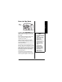
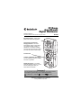
www.radioshack.comSM
29-Range
Auto/Manual
Digital Multimeter
OWNER’S MANUAL —
Completely read this manual before using this meter.
22-813
Bar Graph Display – makes nulls,
peaks, and trends more apparent.
Auto-Ranging with ManualRanging Override – the meter
automatically selects a range when
you measure voltage, current, or
resistance. You can also manually
set the range when measuring values
you know are within a certain range.
Function Dial
Latest IC and Display Technology –
ensures reliability, accuracy, stability,
and ease of operation.
Data Hold Function – The meter
holds the displayed value, so you can
see the reading even after you
disconnect the test leads.
! IMPORTANT !
If an icon appears at the end of a paragraph, go to the box on that
page with the corresponding icon for pertinent information.
— Warning ! — Important
— CautionÓ Ô — Note
o
© 2002 RadioShack Corporation. All Rights Reserved.
RadioShack and RadioShack.com are trademarks
used by RadioShack Corporation.
CONTENTS
A Word About Safety
A Word About Safety ..... 2
Safety Marks ................. 4
Preparation .................... 5
Installing Batteries ..... 5
Connecting the
Test Leads ................. 5
Operation ...................... 6
Taking Accurate
Measurements ........... 6
Turning the Meter
On/Off and
Testing the Display .... 6
Before You Start ......... 7
Holding a
Measurement ............. 9
Automatic
Power Off ................. 10
Using
Power Lock .............. 10
Using the
Bar Graph ................. 11
Making
Measurements ............ 12
Measuring
DC/AC Voltage ........ 12
Measuring
DC/AC Current ........ 14
Measuring
Resistance ............... 15
Checking
Continuity ................. 16
Checking Diodes ..... 17
Checking
Batteries .................. 18
Care ............................ 20
Cleaning .................. 20
Replacing the Fuse .. 20
Specifications .............. 21
2
Thank you for buying a RadioShack 29Range Auto/Manual Digital Multimeter. Your
multimeter is a portable, compact autoranging digital multimeter. It is ideally suited
for field, lab, shop, and home applications.
The multimeter provides accurate
measurements and is built to provide the
highest possible reliability. The meter
measures DC and AC voltage up to 600V,
DC and AC current up to 10A, resistance up
to 40MΩ, and tests 1.5V C, D, AA, AAA, and
9V batteries. Its 33/4-digit digital display can
show up to 4,000 units. Its bar graph display
appears with the digital display to let you
easily see nulls, peaks, and trends.
A WORD ABOUT
SAFETY
We have taken every precaution in
designing this meter to ensure that it is safe.
Safe operation depends on you, the
operator. We recommend that you follow
these simple safety rules.
• This equipment is rated for installation
category II (max. 3600 VA).
• Never apply voltages to the meter that
exceed the limits given in the
specifications. Never apply more than
600V DC or AC between the input
jacks and ground.
• Use extreme caution when working
with voltages above 30V RMS and
42.4V peak or 60V DC. Always disconnect power from the circuit you are
measuring before you connect test
leads to high-voltage points.
• Never connect to a voltage source
when you select the diode check,
•
•
•
•
This meter is fully calibrated and tested.
Under normal use, no further adjustment
should be necessary. If the meter requires
repair, do not try to adjust it yourself. Take it
Ô
to your local RadioShack store.
o
The UL mark does not indicate that this
product has been evaluated by Underwriters
Laboratories for the accuracy of its readings.
•
Your meter requires three AAA batteries (not
supplied).
Your meter also has these additional
features.
Auto Power Off — the meter turns itself off
after about 30 minutes if you do not change
any setting, helping conserve battery power.
Auto-Polarity Operation — protects your
meter and gives valid measurements when
you connect the leads in reverse polarity.
•
•
o
WARNING
o
USE EXTREME
CAUTION IN THE
USE OF THIS
DEVICE, IMPROPER
USE OF THIS
DEVICE CAN
RESULT IN INJURY
OR DEATH.
FOLLOW ALL
SAFEGUARDS
SUGGESTED IN
THIS OWNER’S
MANUAL IN
ADDITION TO
NORMAL SAFETY
PRECAUTIONS IN
DEALING WITH
ELECTRICAL
CIRCUITS. DO NOT
USE THIS DEVICE
IF YOU ARE
UNFAMILIAR WITH
ELECTRICAL
CIRCUITS AND
TESTING
PROCEDURES.
IF THIS EQUIPMENT
IS USED IN A
MANNER NOT
SPECIFIED BY THE
MANUFACTURER,
THE PROTECTION
PROVIDED BY THE
EQUIPMENT MAY
BE IMPAIRED.
TO REDUCE THE
RISK OF FIRE OR
SHOCK HAZARD,
DO NOT EXPOSE
THIS PRODUCT TO
RAIN OR
MOISTURE.
FOR INDOOR USE
ONLY.
3
A Word About Safety
•
continuity function, resistance
measurement, or any of the battery test
or current measurement functions.
Always discharge any capacitors of the
circuit under test before you attach test
leads.
Always turn off power and disconnect the
test leads from the circuit before replacing the meter’s batteries or the fuse.
Never operate the meter unless its
back cover and battery cover are fully
closed and the screws fully tightened.
Because many AC/DC sets have a
potentially hot chassis, be sure the top
of your workbench and the floor
underneath it are made of nonconductive materials.
CAUTION
•
•
Completely read this
manual before using
the meter.
This meter passes
the stringent safety
tests required by
Underwriters
Laboratories.
Diode-Check Function — The meter
safely checks semiconductor junctions for
opens, shorts, or normal.
Battery Test Function — Lets you easily
test batteries under load condition.
Overload and Transient Protection —
helps protect the meter from accidental
overload in most ranges.
SAFETY MARKS
For your safety, we have added special markings to the meter’s panel to
remind you of the measurement limitations.
Safety Marks
The maximum current that this meter can measure at
this jack is 400 mA DC and AC.
Caution: Be extra careful when making highvoltage measurements; DO NOT TOUCH
TERMINALS OR PROBE ENDS.
Caution: Risk of electric shock! Refer to the
complete operating instructions.
The meter is protected by double insulation.
CAT II
This equipment is rated for INSTALLATION
CATEGORY II (3600VA max.).
The maximum voltage that this meter can measure is
600V RMS AC or 600V DC. To avoid electric shock or
instrument damage, do not connect the two input terminals (–COM and +V.Ω.mA) to any source that
exceeds 600 volts with respect to earth/ground.
10A MAX. The maximum current you can measure at this jack is
UNFUSED 10 amps DC/AC. This jack is not fuse-protected.
4
PREPARATION
•
Your meter requires 3 AAA batteries (not
supplied) for power. Batteries are available
at your local RadioShack store or online at
Ô
www.radioshack.com.
o
•
1. Set the function dial to OFF. Then
unplug the test leads.
2. Use a Phillips screwdriver to loosen the
battery cover’s screw on the back of the
meter. Then remove the battery cover.
3. Install the batteries according to the
polarity markings (+ and –) in the
battery compartment.
•
•
When ; appears on the left side of the
display or the meter stops operating
properly, replace the batteries.
•
THE
TEST
•
LEADS
Red
Test
Lead
The test leads (black
and red) supplied with
your meter are rated
for 1000 volts. Use
only test leads of the
same rating as the
Black Test Lead
meter. You can order
replacement leads
from your local RadioShack store.
o
Ô BATTERY NOTES Ô
4. Replace the battery compartment
cover and secure it with the screw.
CONNECTING
WARNING
Although
To
avoid electrical
the test
shock,are
leads
disconnect
rated for
both of
1000
volts,
the test
do not
leads
try
from
to
measure
any equipment
any
before you
voltage
greater
install
than
or
replace
600
voltsthe
DC/600
meter’s
batteries.
volts
RMS AC.
Doyou
If
notconnect
operateone
the
meter
test
lead
until
to the
a hot wire
batteries
first
and touch
are properly
the
installed
the
back
other
testand
lead
tip,
you
could
an
cover
is in receive
place and
electric
secured.shock.
•
Dispose of old
batteries promptly
and properly.
Do not burn or bury
batteries.
Use only fresh
batteries of the
required size and
recommended type.
Do not mix old and
new batteries or
different types of
batteries (standard or
alkaline).
If you do not plan to
use the meter for a
month or more,
remove the batteries.
Batteries can leak
chemicals that can
destroy electronic
parts.
o
5
Preparation
INSTALLING BATTERIES
o
CAUTION
•
Operation
•
Be sure to select the
correct function
before you touch the
test leads to the
circuit or component
to be tested.
When the meter is not
in use, always leave
the function dial set to
OFF.
Ô NOTE Ô
•
•
6
The meter sounds a
warning tone when
you set it to measure
anything except
current and connect
a test lead to + 10A
MAX. This reminds
you not to touch the
circuit with the test
leads.
If the function dial is
not set to OFF and
nothing appears on
the display, the meter
might be in its auto
power shut-off mode.
Press any button or
rotate the function
dial to any position
except OFF to turn on
the meter. If the
meter remains off,
set the function dial
to OFF then set it to
any function except
OFF. If the meter still
remains off, replace
the batteries (see
“Installing Batteries”
on Page 5).
1. Remove the plastic plugs from both test
leads.
2. Plug the black test lead’s right-angled end
into –COM (common) on the front of the meter.
3a. Plug the red test lead’s right-angled end
into +V.Ω.mA on the front of the meter.
OR
3b. To measure current higher than 400 mA,
plug the red test lead’s right-angled end into
+ 10A MAX on the front of the meter.
Ô
OPERATION
TAKING ACCURATE
MEASUREMENTS
For the most accurate reading, the
temperature should be between 65° and
83°F (18° and 28°C) (75% RH maximum).
TURNING THE METER
ON/OFF AND
TESTING THE DISPLAY
To turn on the meter, rotate the function dial
to any function except OFF. To turn off the
meter, rotate the function dial to OFF.
To test the meter’s display, turn off the
meter, and then hold down any button while
turning on the meter. The meter turns on
and all segments on the display appear.
Release the button you are holding down to
turn off the test.
Familiarize yourself with the meter’s
operation before you use it for the first time
by following these steps.
o
1. Rotate the function dial to select one of
the following measurements, then
repeatedly press SELECT to choose the
function you want.
Measurement
o
WARNING
o
Always turn off power to
the circuit you are about
to measure before you
connect the test leads to
high voltage.
Function (select using SELECT
button)
1. Measures DC voltage.
V
2. Measures AC voltage.
1. Measures amperage:
mA/A
¹/§/Ω
• DC 40/400 mA
• AC 40/400 mA
2. Measures amperage:
• DC 4/10 A
• AC 4/10 A
1. Measures resistance.
2. Checks continuity.
3. Checks diodes.
AA/
C/D
Tests 1.5V C, D, and AA
batteries.
AAA
Tests 1.5V AAA batteries.
Tests 9V batteries.
9V
For example, to measure a diode,
rotate the function dial to /
/Ω then
appears.
press SELECT twice.
§
¹§
7
Operation
BEFORE YOU START
Ô NOTE Ô
•
Operation
•
•
8
Overflow is when the
meter tries to display
4001 or more units.
Underflow is when
the meter tries to
display 379 or fewer
units.
If nothing appears on
the display, press
any button to turn on
the meter.
The display might
show a “phantom”
reading in some DC
and AC voltage
ranges when the test
leads are not
connected to a
circuit. This is
normal. The high
input sensitivity
produces a
“wandering” effect.
When you connect
the test leads to a
circuit, a real
measurement
appears.
Your meter automatically enters the
auto range mode when you turn it on.
In the auto range mode, AUTO
appears and the meter automatically
selects the next higher or lower range
(if available) when the measurement
causes the display to overflow or
underflow. Ô
1.
2. To select manual range mode, press
RANGE while the meter is in auto-range
mode. AUTO disappears.
3. Repeatedly press RANGE to select
different ranges. The decimal point
shifts each time you press RANGE.
4. Hold down RANGE for about 2 seconds
to exit manual range mode and return
to its auto-range mode.
5. Set the meter to the different
measurement ranges. The unit of
measure that appears on the display
shows the range that the meter is
currently set to.
For example, mV appears in the 400
mV range. Also, note the position of the
decimal. For example, if 0.000V
appears, the meter is set to measure
less than 4 volts. If 000 V appears, the
meter is set to measure up to 600 volts.
Range
Display
400 mV
ddd.d mV
4V
d.ddd V
40 V
dd.dd V
400 V
ddd.d V
600 V
ddd V
40 mA
dd.dd mA
400 mA
ddd.d mA
4A
d.ddd A
10 A
dd.dd A
400 Ω
ddd.d Ω
4 kΩ
d.ddd kΩ
40 kΩ
dd.dd kΩ
400 kΩ
ddd.d kΩ
4 MΩ
d.ddd MΩ
40 MΩ
dd.dd MΩ
CAUTION
If O.F (overflow) appears,
the value you are
measuring exceeds the
range you set, or you do
not have the test leads
connected to a
component when the
meter is set to its
resistance or diode
function.
This is normal when you
measure resistance or a
diode with O.F appears.
If you are measuring
voltage or current when
O.F appears, however,
immediately disconnect
the test leads from the
circuit.
Ô NOTE Ô
+V.Ω.mA is fuse-
protected. If the meter
does not work, check
the fuse (see “Replacing
the Fuse” on Page 20).
6. Connect the black test lead then the
red test lead to the circuit you want to
measure. To measure different circuits,
see “Making Measurements” on
Ô
Page 12.
HOLDING
A
MEASUREMENT
Press HOLD to hold all indications on the
display. The meter holds the measured
value and Hold appears on the display even
if you remove the test leads from the circuit.
9
Operation
Read the range in volts, amps, or ohms
as indicated by the position of the
decimal point. Ô
To cancel hold, press HOLD again or set the
function dial to another setting. Hold
disappears.
Operation
AUTOMATIC POWER OFF
Your meter conserves power by
automatically turning off about 30 minutes
after the last time you changed the setting
(even if you are making measurements),
The meter beeps as it turns itself off.
o
WARNING
o
Do not change the
function dial’s setting
with the meter’s leads
connected to the circuit
under test.
To turn the meter on after it automatically
turns off, press any button or select another
function.
o
USING POWER LOCK
Follow these steps to set the meter so that it
does not turn off automatically.
1. Rotate the function dial to OFF to turn
off the meter.
2. Hold down HOLD and SELECT at the
same time, then turn on the meter. PLoc
appears.
3. Release HOLD and SELECT. PLoc
disappears and PWR
Lock appears.
To reset the meter so that it automatically
turns itself off, turn off the meter then turn it
on. PWR
Lock disappears.
10
USING
THE
BAR GRAPH
In addition to the numeric display, the meter
displays all measurements on a bar graph
which consists of 8 segments at the top of
the display.
Operation
Bar
Graph
Ô NOTE Ô
•
Each segment represents a value of 500
when you measure voltage, current,
resistance and diodes. Ô
Segments of the bar graph also appear
when the reading is above 0.8 volts for 1.5
volt C/D/AA/AAA size batteries or above 4.8
volts for 9V batteries.
One segment of the bar graph appears for
each 0.1 volt if you are measuring C, D, AA,
and AAA batteries. One segment of the bar
graph appears for each 0.6 volts, if you are
measuring 9-volt batteries. If all segments of
the bar graph appear, the battery being
measured is fresh.Ô
•
Each segment of the
bar graph represents
a unit of
measurement used
by the meter for the
function you
selected. The
segments do not
represent the actual
number of volts,
ohms, and current
measured by the
meter.
The bar graph
updates about 4
times per second,
providing a better
indication of levels
and trends for
different types of
measurements.
For example, if you are measuring DC
voltage and the displayed value is 2.560
volts, 6 segments appear on the bar graph.
11
•
o
Making Measurements
•
WARNING
o
When measuring high
voltages, always
clamp the meter’s
black test lead to
ground or neutral
first, then the red test
lead second. (The hot
wire is usually
colored red, black, or
blue in AC wiring
circuits). If one lead is
clamped to the hot
wire first and you
touch the meter’s
other test lead, you
could receive an
electric shock.
The maximum input
limit for voltage
measurement is
600 V DC/AC (RMS).
To avoid electrical
shock and damage to
the meter, never try to
measure a DC voltage
above 600 volts or an
AC voltage above
600 volts RMS with
respect to ground.
Ô NOTE Ô
When you measure DC
voltage, – appears on
the left side of the
display if you touch the
black test lead to a point
in the circuit that has a
higher voltage potential
than the point where
you connected the red
test lead.
12
MAKING
MEASUREMENTS
MEASURING DC/AC
VOLTAGE o
1. Set the function dial to
V
.
2. Repeatedly press SELECT to select DC
or AC.
appears for AC voltage
measurement.
If the meter is set to automatic range
control, the meter automatically moves
to the range that gives the best
reading.
3. To set manual range control, press
RANGE. Then change the range (if
necessary) by repeatedly pressing
RANGE.
4. Touch the black test lead then the red
test lead to the circuit you want to test.
Ô
If the meter is set to the 400mV DC manual
range and you measure an overrange input,
OF continues to appear even after you
remove the input. This is not a malfunction.
If this happens, touch the test leads together
or change the meter’s setting to clear it. Ô
1. Disconnect power from the circuit you
will test.
•
2. Set the function dial to V . The meter
automatically selects auto range and
the DC measurement mode.
3. Press SELECT to select the AC mode.
appears.
4. Connect the black test lead to the
circuit’s neutral or ground lead.
5. Connect a 0.1 microfarad/100V mylar
capacitor in series with the positive
terminal of the voltage source and the
red test lead.
6. Apply power to the circuit. The display
shows the AC voltage.
o
7. When you finish measuring AC voltage,
turn off the power of the circuit under
test, then disconnect the capacitor you
connected in Step 5.
Measuring Three-Phase
AC Voltage
Your multimeter is designed primarily to
measure household AC voltages. If you
want to measure 3-phase, line-to-line
voltage, please note the following:
• Because of the dangers inherent in
measuring three-phase circuits, we
strongly recommend you do not use
this meter for such applications.
• The actual voltage can be greater than
the circuit’s rated line-to-ground voltage.
•
o
WARNING
o
To avoid injury or
damage to your
meter, never try to
measure an AC
voltage that is riding
on a DC source bias
where the peak AC
voltage exceeds 100
V with respect to
earth ground.
To avoid electrical
shock, do not
physically touch the
test leads, the
capacitor, or the
circuit under test
while applying power.
CAUTION
Before measuring AC
voltage riding on a DC
source bias, measure
the DC voltage first. If it
exceeds 100V, stop
measuring.
Ô NOTE Ô
In the 400 V and 400mV
ranges, the decimal
point appears in the
same position (one
place to the left). To
distinguish between the
two ranges, mV appears
in the 400mV range and
V appears in the 400 V
range.
13
Making Measurements
Measuring AC Voltage Riding
On a DC Source Bias o
•
o
•
WARNING
o
Making Measurements
This voltage (692.8V
AC) exceeds the
meter’s rating.
Therefore, you should
not connect the meter
to this circuit or to any
equipment connected
to the circuit. Doing
so could present a
dangerous shock
hazard to you, and
could also damage
the meter.
When the meter is set
to its current
measurement
function, do not apply
voltage directly
across terminals. You
must connect the
meter in series with
the circuit.
Three-phase industrial circuits are extremely
powerful. You can be burned severely and
even killed if you create an accidental short
in these panels.
Before measuring voltages, put on
protective clothing – a face shield and
fireproof gloves and upper body protection is
required. If you do not have this protection,
DO NOT MEASURE THESE CIRCUITS.
Most 3-phase power circuits are rated by
their line-to-line voltage. This voltage is
higher than the line (or phase) to ground
voltage. To determine if a line-to-line 3phase voltage exceeds the rating of this
meter, multiply the rated line-to-ground
voltage by 1.732 (the square root of 3). For
example, if the rated line-to-ground voltage
is 400 volts, the line-to-line voltage is 400 ×
1.732 = 692.8 V AC.
o
MEASURING DC/AC CURRENT
CAUTION
•
•
14
When the meter is set
to its current measurement function, never
connect the test leads
across a voltage
source. Doing so can
damage the meter or
the circuit under test.
The maximum input
limit for AC/DC current
measurement is 10A.
If you do not know the
amount of current in
the circuit you are
measuring, always
connect the red test
lead to + 10A MAX.
To measure AC or DC current, you must
break the circuit and connect the test leads
to two circuit connection points. The
connection must be in series with the circuit
under test.
o
1. Disconnect power from the circuit you
will test and discharge all capacitors.
2. Rotate the function dial to
mA/A .
3. Repeatedly press SELECT to select DC
or AC.
appears for AC current
measurement.
4. Connect the black test lead to one of
the two connection points on the
broken circuit.
6. Apply power and read the results on
the display. Ô
o
MEASURING RESISTANCE
The resistance measuring circuit in your
meter compares the voltage gained through
a known resistance (internal) with the
voltage developed across an unknown
resistance.
o
1. Disconnect power from the circuit you
will test and discharge all capacitors.
2. Rotate the function dial to
¹/§/Ω.
3. Repeatedly press SELECT to set the
meter to measure resistance.
Ω, Ω, or Ω appears.Ô
K
M
4. Connect the black test lead to one lead
of the component you want to
measure.
5. Connect the red test lead to the other
lead of the component you want to
measure, or remove one of the leads of
the component you want to measure
from its circuit and touch the test leads
across the component. If the meter is
set to automatic range control, it
automatically moves to the proper
range. Ô
WARNING
o
Be sure the circuit under
test has all power
removed and any
associated capacitors
are fully discharged
before you make
resistance
measurements.
CAUTION
Your meter has a circuit
to protect the resistance
range from over-voltage.
However, to prevent
accidentally exceeding
the protection circuit’s
rating and to ensure a
correct measurement,
never connect the test
leads to a source of
voltage while the
function dial is set to
/
/Ω.
¹§
Ô NOTE Ô
•
•
When you are
measuring current, if
your measurement
exceeds the currently
selected range, O.F
appears until the
measured voltage or
current is reduced to
a value below the
currently selected
range.
If the measured
current’s polarity is
negative, – appears
before the value.
15
Making Measurements
5. To measure current larger than 400
mA, plug the red test lead into +10 A
MAX. Otherwise, plug the red test lead
into +V.Ω.mA. Then connect the red test
lead to the other connection point on
the broken circuit.
CAUTION
Do not connect the test
leads to a source of
voltage with the function
dial set to /
/Ω. This
could damage the meter
or the circuit being
connected.
¹§
Ô NOTE Ô
•
Making Measurements
•
•
•
16
The jack labeled
+V.Ω.mA is fuseprotected. If the
meter cannot
measure in 40/
400mA ranges,
check the fuse (see
“Replacing the Fuse”
on Page 20).
With no resistance
connected across the
test leads (meaning
resistance is infinite),
O.F appears when
you set the meter to
measure resistance.
This is normal.
If you want to set the
meter to manual
range mode, press
RANGE to set
manual range mode
and repeatedly press
RANGE to change
the range.
If you are measuring
resistance of about
1MΩ or more, the
display might take a
few seconds to
stabilize. This is
normal.
As with the voltage range, use the
measuring units that appear on the
display to determine the current
resistance range. If only Ω appears, the
values of the measurements are in
ohms. If k and Ω appear, the meter is
measuring kilohms (1 kilohm = 1000Ω).
If M and Ω appear, the meter is
measuring megohms (1 megohm =
1,000,000 Ω).
CHECKING CONTINUITY
You can use the meter to check for shorted
or open electrical circuits.
1. Disconnect power from the circuit you
will test and discharge all capacitors.
2. Rotate the function dial to
¹/§/Ω.
3. Repeatedly press SELECT to select the
continuity function. appears on the
right side of the display.
¹
4. Connect the black test lead to one side
of the circuit you want to check.
5. Connect the red test lead to the other
side of the circuit you want to check.
Shrt appears and the buzzer sounds if
the circuit resistance is less than about
50 ohms (meaning the circuit has low
ohmage or is shorted). Open appears
and the meter’s buzzer does not sound
if the circuit resistance is greater than
about 50 ohms (meaning the circuit is
not shorted and greater than about 50
ohms).
CHECKING DIODES
This procedure lets you check diodes,
transistors, and other semiconductors for
opens, shorts, and normal operation. It also
lets you determine the forward voltage and
polarity for diodes. (This is handy when you
need to match a diode).
CAUTION
Do not connect the test
leads to a source of
voltage with the function
dial set to /
/Ω. This
could damage the meter
or the circuit being
connected.
¹§
1. Disconnect power from the circuit you
will test and discharge all capacitors.
¹/§/Ω.
3. Repeatedly press SELECT to select the
appears on the right
diode function.
side of the display.
§
4. Connect the black test lead to the
cathode or one pin of the component
you want to check.
5. Connect the red test lead to the anode
or the other pin of the component you
want to check, or remove one of the
leads of the component you want to
measure from its circuit and touch the
test leads across the component. Then
note the first reading.
6. Reverse the test leads and note the
second reading.
Ô NOTE Ô
•
•
When you test most
semiconductors, the
values might vary
depending on the
temperature.
The values that
appear during a
diode check show
the actual forward
voltage (max. 1.2V).
If the voltage
exceeds 1.2V, O.F
appears. This means
the diode check
cannot be made
using this meter.
If one reading shows a value and the
other is overrange (.OF appears) the
device is good. If .OF appears during
both readings, the device is open. If
both values are very small or zero, the
device is shorted. Ô
Checking Diode Polarity
Many diodes have a stripe or mark on one
side. The marked side of the diode indicates
17
Making Measurements
2. Rotate the function dial to
the diode’s cathode or negative (–) side. The
other side is the anode or positive (+) side.
CAUTION
Making Measurements
While the function dial is
set to any battery check
function, do not connect
the test leads to a source
of voltage that is not a
battery listed in this
section. This could
damage the meter or the
circuit being connected.
If a diode is not marked, you can use your
meter to check the diode’s polarity. As you
follow the steps under “Checking Diodes” on
Page 17, connect the black test lead to one
side, connect the red test lead to the other
side, then measure and note the voltage.
Then reverse the test leads, and measure
and note the second reading. The side of the
diode where the meter shows a higher
voltage using the red test lead is the anode
(+) side.
CHECKING BATTERIES
The meter can accurately check batteries
under designated load conditions. You can
use the meter to test 1.5V C-, D-, AA-, and
AAA-size batteries and 9V batteries.
1. Rotate the function dial to one of these
settings, depending on the battery you
want to check.
If The Battery You
Are Checking
Is a ...
AA, C, or D
AA/C/D
AAA
AAA
9V
18
Rotate the Function
Dial To ...
9V
Battery
Size
AAA
AA
C
D
9V
Range
< 1 volt
Display
Action
Bad and the Replace
number of
battery.
volts appear.
1 – 1.1 volts Good
flashes and
the number
of volts
appears.
Consider
replacing
battery.
1.1 – 1.5
volts
Good and
the number
of volts
appear.
Battery is
good.
> 1.5 volts
Good and
the number
of volts
appear.
Battery is
full.
< 6 volts
Ô NOTE Ô
•
•
•
•
Bad and the Replace
number of
battery.
volts appear.
6 – 6.6 volts Good
flashes and
the number
of volts
appears.
Consider
replacing
battery.
6.6 – 9 volts Good and
the number
of volts
appear.
Battery is
good.
> 9 volts
Battery is
full.
Good and
the number
of volts
appear.
•
•
When testing 1.5V C,
D, AA and AAA size
batteries, if the
battery’s voltage is
below 0.010 volts,
Bad or Good do not
appear.
When testing 1.5V C,
D, AA and AAA size
batteries, if the
battery’s voltage is
above 2 volts, .OF
appears until the
measured voltage is
reduced to a value
below 2 volts.
When testing a 9V
battery, if the
battery’s voltage is
below 0.10 volts,
Bad or Good do not
appear.
When testing a 9V
battery, if the
battery’s voltage is
above 11 volts, .OF
appears until the
measured voltage is
reduced to a value
below 11 volts.
The jack labeled
+V.Ω.mA is fuseprotected. If the
meter does not
measure properly,
check the fuse (see
“Replacing the Fuse”
on Page 20).
If you connect the
test leads in reverse
polarity, – appears
on the left side of the
display.
19
Making Measurements
2. Connect the black test lead to the
battery’s negative (–) terminal and the red
test lead to the battery’s positive (+)
terminal. Then use this table to
determine the battery’s charge. Ô
CARE
Keep the meter dry; if it gets wet, wipe it dry
immediately. Use and store the meter only in
normal temperature environments. Handle
the meter carefully; do not drop it. Keep the
meter away from dust and dirt, and wipe it
with a damp cloth occasionally to keep it
looking new.
•
o
•
WARNING
o
Do not let any water
drip inside the meter
while cleaning it.
Make sure that the
meter is completely
dry before using it.
CLEANING
To keep the meter looking new, occasionally
wipe it with a cloth slightly dampened with
water. Do not use harsh chemicals, cleaning
solvents, or strong detergents to clean the
meter.
o
REPLACING
THE
FUSE
If the meter does not operate, you might
need to replace the fuse with the supplied
spare fuse.
CAUTION
Care
Do not use a fuse brand or
rating other than these
specified here. Doing so
might damage your meter.
Bottom View
Red Fuse
Ribbon
20
Spare
Fuse
o
1. Set the function dial to OFF and unplug
the test leads.
2. Use a Phillips screwdriver to loosen
both screws on the back cover of the
meter. Then lift off the cover.
o
WARNING
o
To avoid electric shock,
you must disconnect the
test leads before you
remove the back cover.
Do not operate your
meter until the back
cover is in place and
secured.
3. To remove the fuse, gently pull the red
ribbon wrapped around it. The fuse
pops out.
4. If the fuse is blown, discard it and save
the red ribbon. Then remove the supplied
spare fuse, slip it into the ribbon, and
insert the fuse into the fuse holder.
5. Replace the back cover of the meter
then secure it with the screws.
SPECIFICATIONS
Accuracies at 23°C ± 5°C, < 75% RH.
DC VOLTS (Maximum Measurement: 600V)
400mV .................................... ± 0.5% of Reading,
± 4 in Last Digit
4V – 40V – 400V ................... ± 0.8% of Reading,
± 4 in Last Digit
600V ....................................... ± 1.0% of Reading,
± 4 in Last Digit
AC VOLTS (600 V RMS Maximum at 50/60Hz,
Average responds, RMS calibrated, DC Coupled)
400mV .................................... ± 1.2% of Reading,
± 5 in Last Digit
4V ........................................... ± 0.8% of Reading,
± 5 in Last Digit
40 – 400V – 600V .................. ± 1.2% of Reading,
± 5 in Last Digit
21
Specifications
The meter contains a 5 × 20mm, 500mA,
250V ceramic fuse (Radio Shack Cat. No.
270-1070).
Specifications
DC CURRENT (Maximum Measurement: 10A)
40mA – 400mA ...................... ± 1.2% of Reading,
± 4 in Last Digit
4A – 10A ................................ ± 1.5% of Reading,
± 4 in Last Digit
AC CURRENT (Average responds, RMS
calibrated, 10A maximum, DC Coupled)
40mA – 400mA ...................... ± 1.5% of Reading,
± 4 in Last Digit
4A – 10A ................................ ± 2.0% of Reading,
± 4 in Last Digit
RESISTANCE
400 – 4k – 40kΩ .................... ± 1.2% of Reading,
± 4 in Last Digit
400k – 4.0MΩ ......................... ±1.2% of Reading,
± 4 in Last Digit
40MΩ ...................................... ± 2.0% of Reading,
± 4 in Last Digit
BATTERY TEST
1.5V C/D/AA (150mA ± 10% load current) ............
± 5.0% of Reading, ± 4 in Last Digit
1.5V AAA (50mA ± 10% load current) ...................
± 5.0% of Reading, ± 4 in Last Digit
9V Battery (10mA ± 10% load current) ..................
± 5.0% of Reading, ± 4 in Last Digit
DIODE MODE
Open Circuit Voltage .............................. < 1.6Vdc
Test Current ................................ 0.8 mA (Typical)
CONTINUITY BEEPER
Continuity (short): .......................<= 50 ± 30 Ohms
Open:.............................................> 50 ± 30 Ohms
Open Circuit: ..........................................<1.6 Volts
Short Circuit Current:................................ < 1.0 mA
Beeper Volume (at 5 cm) ..................... 65 dB Min.
(audio scale)
22
Specifications
GENERAL
Maximum Common Mode Voltage .........................
600V DC or RMS AC
Battery Life (Alkaline) at 1 hour use per day ..........
About 350 days
Sleep Mode timing ...................... 30 ± 10 Minutes
Range Up Detect Value .......................... Overflow
( >4000 Counts)
Range Down Detect Value ................. 380 Counts
Low Battery Indication ................ lower than 3.35V
± 0.35 V
Sleep Mode current ....................... 25 µA Normal,
40µA Max.
Input Impedance (DCV/ACV) .................. 10 Mohm
Power Source ............................ 3 × AAA batteries
Operating Temperature .................. 41°F to 104°F
(+ 5°C to + 40°C)
Storage Temperature ..................... – 4°F to 140°F
(– 20°C to + 60°C)
Humidity ................... Maximum Relative Humidity
80% for temperatures up to 87.8°F
(31°C), decreasing linearity to 50% relative
humidity at 104°F (40°C)
Pollution Degree .................................................. 2
Altitude ....................... up to 6561.6 feet (2000 m)
Dimensions (HWD) ........... 59/10 × 29/10 × 11/2 In.
(150 × 74 × 38 mm)
Weight ................................... Approx 6 oz (170 g)
Accessories ........... Spare F500mA/250V Fuse (1)
Shrouded Test Leads (Red/Black) (2)
Specifications are typical; individual units
might vary. Specifications are subject to
change and improvement without notice.
23
Limited Ninety-Day Warranty
This product is warranted by RadioShack against manufacturing defects in material and
workmanship under normal use for ninety (90) days from the date of purchase from RadioShack company-owned stores and authorized RadioShack franchisees and dealers. EXCEPT AS PROVIDED HEREIN, RadioShack MAKES NO EXPRESS WARRANTIES AND
ANY IMPLIED WARRANTIES, INCLUDING THOSE OF MERCHANTABILITY AND FITNESS FOR A PARTICULAR PURPOSE, ARE LIMITED IN DURATION TO THE DURATION OF THE WRITTEN LIMITED WARRANTIES CONTAINED HEREIN. EXCEPT AS
PROVIDED HEREIN, RadioShack SHALL HAVE NO LIABILITY OR RESPONSIBILITY TO
CUSTOMER OR ANY OTHER PERSON OR ENTITY WITH RESPECT TO ANY LIABILITY,
LOSS OR DAMAGE CAUSED DIRECTLY OR INDIRECTLY BY USE OR PERFORMANCE
OF THE PRODUCT OR ARISING OUT OF ANY BREACH OF THIS WARRANTY, INCLUDING, BUT NOT LIMITED TO, ANY DAMAGES RESULTING FROM INCONVENIENCE,
LOSS OF TIME, DATA, PROPERTY, REVENUE, OR PROFIT OR ANY INDIRECT, SPECIAL, INCIDENTAL, OR CONSEQUENTIAL DAMAGES, EVEN IF RadioShack HAS BEEN
ADVISED OF THE POSSIBILITY OF SUCH DAMAGES.
Some states do not allow limitations on how long an implied warranty lasts or the exclusion
or limitation of incidental or consequential damages, so the above limitations or exclusions
may not apply to you.
In the event of a product defect during the warranty period, take the product and the RadioShack sales receipt as proof of purchase date to any RadioShack store. RadioShack
will, at its option, unless otherwise provided by law: (a) correct the defect by product repair
without charge for parts and labor; (b) replace the product with one of the same or similar
design; or (c) refund the purchase price. All replaced parts and products, and products on
which a refund is made, become the property of RadioShack. New or reconditioned parts
and products may be used in the performance of warranty service. Repaired or replaced
parts and products are warranted for the remainder of the original warranty period. You will
be charged for repair or replacement of the product made after the expiration of the warranty period.
This warranty does not cover: (a) damage or failure caused by or attributable to acts of God,
abuse, accident, misuse, improper or abnormal usage, failure to follow instructions, improper installation or maintenance, alteration, lightning or other incidence of excess voltage
or current; (b) any repairs other than those provided by a RadioShack Authorized Service
Facility; (c) consumables such as fuses or batteries; (d) cosmetic damage; (e) transportation, shipping or insurance costs; or (f) costs of product removal, installation, set-up service
adjustment or reinstallation.
This warranty gives you specific legal rights, and you may also have other rights which vary
from state to state.
RadioShack Customer Relations, 200 Taylor Street,
6th Floor, Fort Worth, TX 76102
12/99
RadioShack Corporation
Fort Worth, Texas 76102
22-813
AO0117AAA1
11A02
Printed in China