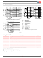
1
Installation, use and maintenance instructions Kerosene burners One stage operation CODE MODEL TYPE 3516010 RDB1 WORCESTER GREENSTAR 12/18 484LD2X 3516020 RDB2.2 WORCESTER GREENSTAR 18/25 744LD2SX 20015255 RDB2.2 WORCESTER GREENSTAR 25/32 744T2K 2903266 (6) - 01/2011 Contents 1 Declaration.................................................................................................................................................................................. 3 2 Information and general warnings............................................................................................................................................ 4 2.1 Information about the instruction manual........................................................................................................................ 4 2.1.1 Introduction ..................................................................................................................................................................... 4 2.1.2 General dangers ............................................................................................................................................................. 4 2.1.3 Danger: live components ................................................................................................................................................ 4 2.2 Guarantee and responsibility .......................................................................................................................................... 5 2.3 Guidance for the use of bio fuel blends up to 10% where gas oil use is permitted by the appliance Manufacturer ....... 5 2.3.1 Information and general instructions............................................................................................................................... 6 2.3.2 Product Disclaimer Statement ........................................................................................................................................ 6 3 Safety and prevention................................................................................................................................................................ 7 3.1 Introduction ..................................................................................................................................................................... 7 3.2 3.3 3.4 Safety warnings .............................................................................................................................................................. 7 Basic safety rules............................................................................................................................................................ 7 Personnel training........................................................................................................................................................... 7 4 Technical description of the burner ......................................................................................................................................... 8 4.1 Technical data ................................................................................................................................................................ 8 4.2 Burner description........................................................................................................................................................... 8 4.3 Burner equipment ........................................................................................................................................................... 8 4.4 Burner dimensions.......................................................................................................................................................... 9 4.5 Firing rates...................................................................................................................................................................... 9 5 Installation ................................................................................................................................................................................ 10 5.1 Notes on safety for the installation................................................................................................................................ 10 5.2 Handling........................................................................................................................................................................ 10 5.3 Preliminary checks........................................................................................................................................................ 10 5.4 Installer/Servicer notes for the use of Gas oil with Bio blends up to 10% where gas oil use is permitted by the appliance Manufacturer .......................................................................................................................................... 11 5.5 Working position ........................................................................................................................................................... 11 5.6 Boiler fixing ................................................................................................................................................................... 12 5.7 Burner assembly........................................................................................................................................................... 12 6 Hydraulic systems.................................................................................................................................................................... 14 6.1 Fuel supply ................................................................................................................................................................... 14 6.1.1 Pump ............................................................................................................................................................................ 14 6.2 One pipe system........................................................................................................................................................... 15 6.2.1 Priming pump................................................................................................................................................................ 15 6.3 Two pipe system........................................................................................................................................................... 16 6.3.1 Priming pump................................................................................................................................................................ 16 7 Electrical system ...................................................................................................................................................................... 17 7.1 Notes on safety for the electrical wiring ........................................................................................................................ 17 7.2 Electrical wiring............................................................................................................................................................. 18 7.2.1 Control box ................................................................................................................................................................... 18 7.2.2 Motor capacitor ............................................................................................................................................................. 18 8 Start-up, calibration and operation of the burner ................................................................................................................. 19 8.1 Notes on safety for the first start-up.............................................................................................................................. 19 8.2 Combustion adjustment ................................................................................................................................................ 19 8.3 Nozzles installation ....................................................................................................................................................... 19 8.3.1 Nozzles reccomended .................................................................................................................................................. 19 8.4 8.5 8.6 8.7 8.7.1 8.7.2 Pump pressure ............................................................................................................................................................. 20 Air damper adjustment.................................................................................................................................................. 20 Electrodes setting ......................................................................................................................................................... 20 Operation programme................................................................................................................................................... 21 Table of timings ............................................................................................................................................................ 21 Operations status indication ......................................................................................................................................... 22 1 GB 3266 Contents 8.7.3 Fault diagnostics ...........................................................................................................................................................22 8.7.4 Recycle function ............................................................................................................................................................23 8.7.5 Flame failure at the end of safety time ..........................................................................................................................23 8.7.6 Lock-out and reset.........................................................................................................................................................23 8.7.7 Limit of continuous ignitions ..........................................................................................................................................23 8.7.8 Ignition prevented in case of extraneous light ...............................................................................................................23 8.7.9 Shut-down test ..............................................................................................................................................................23 8.7.10 Undervoltage and overvoltage protection......................................................................................................................23 8.7.11 Automatic pump priming................................................................................................................................................23 8.7.12 Lock-out types ...............................................................................................................................................................24 8.7.13 Controlled intermittent operation ...................................................................................................................................24 9 Maintenance ..............................................................................................................................................................................25 9.1 Notes on safety for the maintenance.............................................................................................................................25 9.2 Maintenance programme ..............................................................................................................................................25 9.2.1 Maintenance frequency .................................................................................................................................................25 9.2.2 Checking and cleaning ..................................................................................................................................................25 10 Faults / Solutions ......................................................................................................................................................................26 10.1 Burner start-up difficulties..............................................................................................................................................26 10.1.1 Operating faults .............................................................................................................................................................27 3266 2 GB Declaration 1 Declaration Declaration of conformity in accordance with ISO / IEC 17050-1 Manufacturer: RIELLO S.p.A. Address: Via Pilade Riello, 7 37045 Legnago (VR) Product: Kerosene and gas oil burners Model: RDB1 WORCESTER GREENSTAR 12/18 RDB2.2 WORCESTER GREENSTAR 18/25 RDB2.2 WORCESTER GREENSTAR 25/32 These products are in compliance with the following Technical Standard: EN 292 EN 267 and according to the European Directives: MD 2006/42/EC Machine Directive LVD 73/23/EEC - 2006/95/EC Low Voltage Directive EMC 89/336/EEC - 2004/108/EC Electromagnetic Compatibility The quality is guaranteed by a quality and management system certified in accordance with UNI EN ISO 9001. Legnago, 30.07.2010 Mr. G. Conticini Burners Division Department RIELLO S.p.A. 3 GB 3266 Information and general warnings 2 Information and general warnings 2.1 Information about the instruction manual 2.1.1 Introduction 2.1.3 The instruction manual supplied with the burner: is an integral and essential part of the product and must not be separated from it; it must therefore be kept carefully for any necessary consultation and must accompany the burner even if it is transferred to another owner or user, or to another system. If the manual is lost or damaged, another copy must be requested from the Technical Assistance Service of the area; is designed for use by qualified personnel; offers important indications and instructions relating to the installation safety, start-up, use and maintenance of the burner. Danger: live components This symbol indicates operations which, if not carried out correctly, lead to electric shocks with lethal consequences. DANGER Other symbols ENVIRONMENTAL PROTECTION This symbol gives indications for the use of the machine with respect for the environment. This symbol indicates a list. Symbols used in the manual In some parts of the manual you will see triangular DANGER signs. Pay great attention to these, as they indicate a situation of potential danger. 2.1.2 General dangers The dangers can be of 3 levels, as indicated below. DANGER Maximum danger level! This symbol indicates operations which, if not carried out correctly, cause serious injury, death or long-term health risks. This symbol indicates operations which, if not carried out correctly, may cause serious injury, death or long-term health risks. WARNING Abbreviations used Ch. Fig. Page Sec. Tab. Chapter Figure Page Section Table Delivery of the system and the instruction manual When the system is delivered, it is important that: the instruction manual is delivered to the user by the system manufacturer, with the recommendation to keep it in the room where the heat generator is to be installed. The instruction manual shows: – the serial number of the burner; This symbol indicates operations which, if not carried out correctly, may cause damage to the machine and/or injury to people. ......................................................................................... CAUTION – the address and telephone number of the nearest Assistance Centre. ......................................................................................... ......................................................................................... ......................................................................................... The system supplier must carefully inform the user about: – the use of the system; – any further tests that may be required before activating the system; – maintenance, and the need to have the system checked at least once a year by a representative of the manufacturer or another specialised technician. To ensure a periodic check, the manufacturer recommends the drawing up of a Maintenance Contract. 3266 4 GB Information and general warnings 2.2 Guarantee and responsibility The manufacturer guarantees its new products from the installation date, in accordance with the regulations in force and/or the sales contract. At the moment of the first start-up, check that the burner is integral and complete. WARNING Failure to observe the information given in this manual, operating negligence, incorrect installation and carrying out of non authorised modifications will result in the annulment by the manufacturer of the guarantee that it supplies with the burner. In particular, the rights to the guarantee and the responsibility will no longer be valid, in the event of damage to things or injury to people, if such damage/injury was due to any of the following causes: incorrect installation, start-up, use and maintenance of the burner; improper, incorrect or unreasonable use of the burner; intervention of unqualified personnel; carrying out of unauthorised modifications on the equipment; use of the burner with safety devices that are faulty, incorrectly applied and/or not working; installation of untested supplementary components on the burner; powering of the burner with unsuitable fuels; faults in the fuel supply system; continuation of use of the burner when a fault has occured; repairs and/or overhauls incorrectly carried out; modification of the combustion chamber with inserts that prevent the regular development of the structurally established flame; insufficient and inappropriate surveillance and care of those burner components most likely to be subject to wear and tear; the use of non-original components, including spare parts, kits, accessories and optional; force majeure. 2.3 The manufacturer furthermore declines any and every responsibility for the failure to observe the contents of this manual. Riello warranty is subject to correct burner, appliance and application matching, and set up in line with Riello's instructions and guidelines. All components within the hydraulic circuit suitable for bio fuel use and supplied by Riello will be identified as Bio compatible. No warranty is given in relation to the use of components which are not so identified with bio fuel blends. If in any doubt please contact Riello for further advice. If any Riello burners are used with fuel with a bio content >10% then the components within the hydraulic circuit maybe affected and are not covered under warranty. The hydraulic circuit consists of: – – – – 1 2 3 Pump Hydraulic ram (where applicable) Valve block Flexible oil lines (considered as a consumable component) Irrespective of any warranty given by Riello in relation to normal use and manufacturing defects, when fuels not meeting the relevant standards are used, or where fuel storage issues have not been addressed correctly, or the equipment used is not compatible, if failures occur which are directly or indirectly attributed to such issues and/or to the non-observance of this guidance, then no warranty or liability is implied or accepted by Riello. Riello have carefully chosen the specification of the bio compatible components including the flexible oil lines to protect the pump, safety value and nozzle. The Riello warranty is dependent upon the use of Riello genuine components including the oil lines, being used. Riello warranty does not cover defects arising from incorrect commissioning or servicing by non Riello employed service engineers, and any issues impacting the burner arising from external site related issues. Guidance for the use of bio fuel blends up to 10% where gas oil use is permitted by the appliance Manufacturer Backgroun With increasing focus on renewable and sustainable energy requirements, Bio fuel usage is set to increase. Riello is committed to promoting energy conservation and the use of renewable energy from sustainable resources including liquid bio fuels, however there are some technical aspects that must be considered at the planning stage of using such fuels to reduce the potential for equipment failure or the risks of fuel leakage. Liquid Bio fuel is a generic description used for oil that can come from numerous feed stocks including recycled cooking oils. These types of oils have to be considered and treated differently from standard mineral or fossil fuels, as they are generally more acidic, hydroscopic and less stable. Due to this, a holistic approach is needed from the specification of the liquid Bio fuel, the storage of the fuel, its oil supply line and ancillary equipment, and very importantly the oil filtration and the burner itself. The specification for FAME (Fatty Acids Methyl Ester) liquid Bio fuel is critical to reliable equipment operation. It is a minimum requirement that the fuel blend (up to 10% Bio) is obtained with gasoil in accordance with the relevant EN standards, regional regulations and FAME in accordance with EN 14214. It is also important that the fuel blends meet the require- ments related to operational environment conditions within the relevant EN standards. When choosing your Riello oil products where you know Bio fuels will be in use, please make sure that a Bio compatible burner and/ or components have been supplied. If an existing burner is to be used with a liquid Bio fuel then a kit may be required to make it compatible and the guidance notes enclosed concerning oil storage and filtration must be adhered to. The end user is responsible for the thorough verification of the potential risks associated with the introduction of a bio fuel blend and the suitability of the appliances and installation applicable. Irrespective of any warranty given by Riello in relation to normal use and manufacturing defects, when fuels not meeting the relevant standards are used, or where fuel storage issues have not been addressed correctly, or the equipment used is not compatible, if failures occur which are directly or indirectly attributed to such issues and/or to the non-observance of this guidance, then no warranty or liability is implied or accepted by Riello. 5 GB 3266 Information and general warnings 2.3.1 Information and general instructions 2.3.2 To ensure consistency, the supplier of the fuel must be able to demonstrate compliance with a recognised Quality Control and management system to ensure high standards are maintained within the storage, blending and delivery processes. The installation oil storage tank and its ancillaries must also be prepared BEFORE liquid Bio fuel is introduced. Checks and preparation should include: For new installations, make sure that all materials and seals in the oil storage and supply line to the burner are compatible with Bio fuels. For all installations, there must be a good quality bio compatible oil filter at the tank and then a secondary filter of 60 Microns protecting the burner from contamination. If an existing oil storage tank is to be used then in addition to the materials checks as detailed above, it will be essential that the tank is first inspected for condition and checked for water or other contamination. Riello strongly recommends that the tank is cleaned and oil filters replaced prior to Bio fuel delivery. If this is not completed then due to the hydroscopic nature of Bio fuel, it will effectively clean the tank, absorb water present which in turn will result in equipment failure that is not covered by the manufacturer's warranty. Depending on the capacity of the oil storage tank and oil usage, fuels may remain static within the tank for some considerable time and so Riello recommends that the oil distributor is consulted regarding the use of additional Biocides within the fuel to prevent microbial growth from occurring within the tank. Riello suggests that fuel suppliers and or service companies are contacted for guidance on fuel filtration. Special attention should be applied to duel fuel applications where oil may be stored for long periods of time. The burner must be set according to the appliance application and commissioned checking that all combustion parameters are as recommended in the appliance technical manual. Riello recommends that the in line and burner oil pump filters are inspected and if required replaced at least every 4 months during burner use, before the burner start-up following a long period of discontinue operation and even more frequently where contamination has occurred. Particular attention is needed when inspecting and checking for fuel leakages from seals, gaskets and hoses. 3266 Product Disclaimer Statement CAREFULLY READ THE FOLLOWING DISCLAIMER. YOU ACCEPT AND AGREE TO BE BOUND BY THIS DISCLAIMER BY PURCHASING RIELLO BIO COMPATIBLE BURNERS AND/OR COMPONENTS. Although the information and recommendations (hereinafter “Information”) in this guidance is presented in good faith, believed to be correct and has been carefully checked, Riello (and its subsidiaries) makes no representations or warranties as to the completeness or accuracy of the Information. Information is supplied upon the condition that the persons receiving same will make their own determination as to its suitability for their purposes prior to use. In no event will Riello (and its subsidiaries) be responsible for damages of any nature whatsoever resulting from the use of or reliance upon Information. Other than set forth herein, Riello (and its subsidiaries) makes no additional warranties with respect to the bio compatible burner, either express or implied, including that of merchantability or fitness for a particular purpose or use. In no event shall Riello (and its subsidiaries) be liable for any indirect, incidental, special or consequential damages including, without limitation, loss of profits, damages for loss of business profits, business interruption, loss of business information, loss of equipment, or other pecuniary loss or compensation for services whether or not it is advised of the possibility of such damages. With the exception of injuries to persons, Riello's liability is limited to the customer's right to return defective/non-conforming products as provided by the relevant product warranty. 6 GB Safety and prevention 3 3.1 Safety and prevention Introduction The burners have been designed and built in compliance with current regulations and directives, applying the known technical rules of safety and envisaging all the potential danger situations. It is necessary, however, to bear in mind that the imprudent and clumsy use of the equipment may lead to situations of death risk for the user or third parties, as well as the damaging of the burner or other items. Inattention, thoughtlessness and excessive confidence often cause accidents; the same applies to tiredness and sleepiness. It is a good idea to remember the following: The burner must only be used as expressly described. Any other use should be considered improper and therefore dangerous. In particular: the type and pressure of the fuel, the voltage and frequency of the electrical power supply, the minimum and maximum deliveries for which the burner has been regulated, the pressurisation of the combustion chamber, the dimensions of the combustion chamber and the room temperature must all be within the values indicated in the instruction manual. Modification of the burner to alter its performance and destinations is not allowed. The burner must be used in exemplary technical safety conditions. Any disturbances that could compromise safety must be quickly eliminated. Opening or tampering with the burner components is not allowed, apart from the parts requiring maintenance. only those parts detailed as available as spare parts by the manufacturer can be replaced. it can be applied to boilers operating with water, steam, diathermic oil, and to other uses expressly named by the manufacturer; 3.2 Safety warnings The dimension of the boiler’s combustion chamber must respond to specific values, in order to guarantee a combustion with the lowest polluting emissions rate. The Technical Service Personnel will be glad to give you all the imformation for a correct matching of this burner to the boiler. 3.3 3.4 This burner must only be used for the application it was designed for. The manufacturer accepts no liability within or without the contract for any damage caused to people, animals and property due to installation, adjustment and maintenance errors or to improper use. Basic safety rules Children or inexpert persons must not use the appliance. Under no circumstances must the intake grids, dissipation grids and ventilation vents in the installation room be covered up with cloths, paper or any other material. Unauthorised persons must not attempt to repair the appliance. It is dangerous to pull or twist the electric leads. Cleaning operations must not be performed if the appliance is not disconnected from the main power supply. Do not clean the burner or its parts with inflammable substances (e.g. petrol, alcohol, etc.). The cover must be cleaned with soapy water. Do not place anything on the burner. Do not block or reduce the size of the ventilation vents in the installation room. Do not leave containers and inflammable products or combustible materials in the installation room. Personnel training The user is the person, body or company that has acquired the machine and intends to use it for the specific purpose. He is responsible for the machine and for the training of the people working around it. The user: undertakes to entrust the machine exclusively to suitably trained and qualified personnel; must take all the measures necessary to prevent unauthorised people gaining access to the machine; undertakes to inform his personnel in a suitable way about the application and observance of the safety instructions. With that aim, he undertakes to ensure that everyone knows the use and safety instructions for his own duties; must inform the manufacturer if faults or malfunctioning of the accident prevention systems are noticed, along with any presumed danger situation. Personnel must always use the personal protective equipment envisaged by legislation and follow the indications given in this manual. Personnel must observe all the danger and caution indications shown on the machine. Personnel must not carry out, on their own initiative, operations or interventions that are not within their province. Personnel must inform their superiors of every problem or dangerous situation that may arise. The assembly of parts of other makes, or any modifications, can alter the characteristics of the machine and hence compromise operating safety. The manufacturer therefore declines any and every responsibility for any damage that may be caused by the use of non-original parts. 7 GB 3266 Technical description of the burner 4 4.1 Technical description of the burner Technical data Type Output - Thermal power (with air at 20 °C) 3516010 3516020 20015255 1.0 – 1.5 kg/h 12 – 18 kW 1.5 – 2.1 V 18 – 25 kW 2.1 – 2.7 kg/h 25 – 32 kW Fuel Kerosene, viscosity 1.6 – 6 mm2/s at 20 °C (Hi = 11.97 kWh/kg) Electrical supply Single phase, Motor Run current 0.7A ~ 50Hz 230V ± 10% – 2700 rpm – 283 rad/s 4.5 F Capacitor Control box MO535 (digital applications) Ignition transformer Secondary 8 kV Pump – 16 mA (integrated into the control boxes) Kerosene, maximum pressure 10 bar (145 psi) Absorbed electrical power 0.115 kW 0.16 kW Tab. A 4.2 Burner description 1 2 3 11 10 4 9 5 6 7 8 D7353 1 2 3 4 5 6 4.3 Fig. 1 7 8 9 10 11 Reset button with lock-out lamp Flame detector Snorkel Blast tube Air damper adjustment screw Pump Hose Capacitor Pump pressure adjustment screw Control box Coil protection Burner equipment Screw of by-pass pump....................................................... No. 1 The hoses supplied with this burner set for Kerosene use are not suitable for use with Gas oil containing a Bio blend. WARNING Please refer to the spare part list for the specific hoses suitable for bio fuel use. In case of use with gas oil containing up to 10% Bio blend, it will be essential to use flexible oil lines suitable for bio fuel use. Please contact Riello for further information. 3266 8 GB Technical description of the burner 4.4 Burner dimensions B 204 A ø 254 169 225.5 68 ø 90 136 A B 3516010 3516020 158 68 20015255 168 98 D7354 12 Fig. 2 4.5 Firing rates The MAXIMUM OUTPUT is chosen from within the diagram area (Fig. 3). The MINIMUM OUTPUT must not be lower than the minimum limit of the diagram. The work point may be found by plotting a vertical line from the desired delivery and a horizontal line from the pressure in the combustion chamber. The intersection of these two lines is the work point which must lie within the firing rates. The burner delivery must be selected within area of the diagrams (Fig. 3). This area is called firing rates and provides the maximum delivery of the burner in relation to the pressure in the combustion chamber. The firing rate area values have been obtained considering a surrounding temperature of 20 °C, and an atmospheric pressure of 1013 mbar (approx. 0 m above sea level) and with the combustion head adjusted as shown on page 19. WARNING Pressure in the combustion chamber – mbar D7355 4 3 2 3516020 20015255 1 3516010 0 10 12 1 14 16 18 1.5 20 22 24 26 2 28 30 2.5 32 34 36 Thermal power - kW Fuel output - kg/h Fig. 3 9 GB 3266 Installation 5 5.1 Installation Notes on safety for the installation After carefully cleaning all around the area where the burner will be installed, and arranging the correct lighting of the environment, proceed with the installation operations. All the installation, maintenance and disassembly operations must be carried out with the electricity supply disconnected. WARNING The installation of the burner must be carried out by qualified personnel, as indicated in this manual and in compliance with the standards and regulations of the laws in force. DANGER 5.2 Handling The packaging of the burner includes a carton box, so it is possible to move the burner (still packaged) with a transpallet truck or fork lift truck. WARNING 5.3 The handling operations for the burner can be highly dangerous if not carried out with the greatest attention: keep any unauthorised people at a distance; check the integrity and suitableness of the available means of handling. Check also that the area in which you are working is empty and that there is an adequate escape area (i.e. a free, safe area to which you can quickly move if the burner should fall). When handling, keep the load at not more than 20-25 cm from the ground. CAUTION After positioning the burner near the installation point, correctly dispose of all residual packaging, separating the various types of material. Before proceeding with the installation operations, carefully clean all around the area where the burner will be installed. Preliminary checks Checking the consignment After removing all the packaging, check the integrity of the contents. In the event of doubt, do not use the burner; contact the supplier. The output of the burner must be within the boiler's firing rate; WARNING CAUTION The packaging elements (wooden cage or cardboard box, nails, clips, plastic bags, etc.) must not be abandoned as they are potential sources of danger and pollution; they should be collected and disposed of in the appropriate places. Checking the characteristics of the burner D9370 Fig. 4 Check the identification label of the burner, showing: the model A)(Fig. 4) and type of burner B); the year of manufacture, in cryptographic form C); the serial number D); the electrical input power E); the types of fuel used and the relative supply pressures F); the data of the burner's minimum and maximum output possibilities G)(see Firing rate) 3266 10 GB WARNING A burner label that has been tampered with, removed or is missing, along with anything else that prevents the definite identification of the burner makes any installation or maintenance work difficult. Installation 5.4 Installer/Servicer notes for the use of Gas oil with Bio blends up to 10% where gas oil use is permitted by the appliance Manufacturer During the burner installation, check that the gasoil and bio fuel blends are in accordance with Riello specifications (please refer to the chapters "Technical Data" and "Guidance for the use of bio fuel blends up to 10%" within the burner technical manual). If a Bio blend is in use the installer must seek information from the end user that their fuel supplier can evidence that the blends of fuel conform to the relevant standards. Check that the materials used in the construction of the oil tank and ancillary equipment are suitable for bio fuels, If not these must be upgraded or replaced with Bio compatible parts. Particular attention should be given to the oil storage tank and supply to the burner. Riello recommends that existing oil storage tanks are cleaned, inspected and any traces of water are removed BEFORE bio fuel is introduced (Contact the tank manufacturer or oil supplier for further advice). If these recommendations are not respected this will increase the risk of contamination and possible equipment failure. In line oil filters should be replaced making sure that they are Bio compatible. Riello recommends a good quality bio 5.5 compatible oil filter at the tank and a secondary 60 micron filter are used to protect the burner pump and nozzle from contamination. The burner hydraulic components and flexible oil lines must be suitable for bio fuel use (check with Riello if in doubt). Riello have carefully chosen the specification of the bio compatible components including the flexible oil lines to protect the pump, safety value and nozzle. The Riello warranty is dependent upon the use of Riello genuine components including the oil lines, being used. The burner must be commissioned and combustion parameters set to appliance manufacturer's recommendations. Regularly check visually for any signs of oil leakage from seals, gaskets and hoses. It is strongly recommended that with Bio fuel use, oil filters are inspected and replaced every 4 months. More regularly where contamination is experienced. During extended periods of non operation and/or where burners are using oil as a standby fuel, it is strongly recommended that the burner is put into operation for shorts periods at least every three months. Working position WARNING The burner is designed to operate only in the positions 1, and 3 (Fig. 5). Installation 1 is preferable, as it is the only one that allows performing maintenance operations as described in this manual. Installations 2, 3 and 4 allow working operations but not maintenance with hooking to the boiler. 1 2 DANGER 3 Any other position could compromise the correct operation of the appliance. Installation 5 is forbidden for safety reasons. 4 5 D7356 Fig. 5 11 GB 3266 Installation 5.6 Boiler fixing Align burner combustion head (1) interposing the insulating gasket (2), into the boiler housing tube (3). Push firmly down to compress the gasket (2). Tighten the two screw (4) sufficiently to ensure a good seal. Make sure any electrical cable and flexible oil line are routed away from hot surfaces. The seal between burner and boiler must be airtight. WARNING 3 D7383 4 1 D7419 Fig. 7 2 Fig. 6 5.7 Burner assembly The temperature of the incoming air must not exceed 70 °C. CAUTION 1 Consequently, you must comply with the following requirements and instructions: The combustion air intake tube must be: - fastened securely to the burner; - made of a suitable material, with temperature characteristics in the range - 30 °C to 80 °C; - in compliance with all requirements of applicable regulations in force in the country of destination. The intake-tube / burner system must not allow a loss of over 2 m3/h at 0.5 mbar: for instance, the above requirements will be met if you use flues for pressure exhaust of flue gases (the condensation kind). Make sure the air intake tube’s inlet is positioned so that it is not likely to be obstructed by foreign matter and, where necessary, use suitable screens. The inside diameter of the hose must be at least 80 mm. The intake tube can be up to 6 metres in length. Length is reduced if there are bends in the intake section. D7418 Fig. 8 WARNING The combustion air supply is through a flexible or rigid pipe connected to the air intake. 3266 12 GB For instance, using a tube with a smooth inside surface, you must allow for the following losses: – for each 45° bend, tube length is reduced by 0.5 m; – for each 90° bend, tube length is reduced by 0.8 m. Installation NOTE: Burner installation must comply with one of the installations illustrated in the figures below. WARNING Under no circumstances should the air’s entry in the hose intake area be obstructed. The hose must not be blocked in any way or feature a shutting device (valves, membranes etc.). Coaxial tubes must not be installed for any reason. S7851 S7876 S7853 13 GB Fig. 9 Fig. 10 Fig. 11 3266 Hydraulic systems 6 6.1 6.1.1 Hydraulic systems Fuel supply Pump Where gas oil containing bio diesel is in use, it is recommended to avoid over oxygenation of the blended fuels. The pump is designed to allow working with one pipe. In order to obtain two pipes working it is necessary to unscrew the return plug 2)(Fig. 12), screw the by-pass screw 3),supplied as burner equipment and then screw the return hose. WARNING 7 If this cannot be avoided make sure that the return pipe is normally below the surface of the fuel level within the storage tank. See Fig. 15. 6 The suction plug 1) is made of plastic. Once removed, it must not be used again. WARNING 5 WARNING 3 1 2 D10934 Fig. 12 Key (Fig. 12) 1 2 3 4 3266 Suction line Return line By-pass screw Gauge connection 5 6 7 8 In single pipe installations, the plug in the return line 2) must be totally in steel. In case of use with gas oil containing up to 10% Bio blend, it will be essential to use flexible oil lines suitable for bio fuel use. 4 8 Where at all possible avoid the use of two pipe systems where the circulated fuel is returned to the tank. Pressure adjuster Vacuum gauge connection Valve Auxiliary pressure test point 14 GB Please contact Riello for further information. Hydraulic systems 6.2 One pipe system max. 4 m H Pressurised one pipe systems (Fig. 13) have a positive fuel pressure on intake to the burner. Usually the tank is higher than the burner, or the fuel pumping systems are on the outside of the boiler. Vacuum one pipe systems (Fig. 14) have a negative fuel pressure (depression) on intake to the burner. Usually the tank is lower than the burner. You are advised to use additional filters on the fuel supply line. Riello recommends a good quality fuel filter at the tank (Fig. 13 - Fig. 14) and a secondary filter (60 for gas oil and 15 for kerosene) are used to protect the burner pump and nozzle from contamination. H CAUTION In case of Biodiesel use, pay attention to install Biocompatible filters. 6.2.1 D11010 Priming pump Fig. 14 On the system in Fig. 13 it is sufficient to loosen the plug of the vacuum gauge 6)(Fig. 12) and wait until the fuel flows out. On the system in Fig. 14 start the burner and wait for the priming. Should lock-out occur prior to the arrival of the fuel, await at least 20 seconds before repeating the operation. WARNING The installer must ensure that the supply pressure is not above 0.5 bar. Above that level, the pump seal is subject to too much stress. L metres H metres I.D. (8 mm) I.D. (10 mm) 0 0.5 1 1.5 2 3 3.5 35 30 25 20 15 8 6 100 100 100 90 70 30 20 Tab. C min. 0.1 m H max. 4 m H difference of level L max. lenght of the suction line I.D. interminal diameter of the oil pipes NOTE: The Tab. B and Tab. C show the maximum approximate lengths for the supply line, depending on the difference in level, length, and the diameter of the fuel conduit. D11009 Fig. 13 L metres H metres I.D. (8 mm) I.D. (10 mm) 0.5 1 1.5 2 10 20 40 60 20 40 80 100 Tab. B 15 GB 3266 Hydraulic systems 6.3 Two pipe system max. 4 m H Vacuum two pipe systems (Fig. 15) have a negative fuel pressure (depression) on intake to the burner. Usually the tank is lower than the burner. The return line should terminate in the oil tank at the same level as the suction line; in this case a non-return valve is not required. Should however the return line arrives over the fuel level, the non-return valve is indispensable. This solution however is less safe than previous one, due to the possibility of leakage of the valve. You are advised to use additional filters on the fuel supply line. Riello recommends a good quality fuel filter at the tank (Fig. 15) and a secondary filter (60 for gas oil and 15 for kerosene) are used to protect the burner pump and nozzle from contamination. H CAUTION In case of Biodiesel use, pay attention to install Biocompatible filters. D10011 6.3.1 Priming pump WARNING Fig. 15 Before starting the burner make sure that the return pipe-line is not clogged: any obstruction would cause the pump seals to break. On the system in Fig. 15 start the burner and wait for the priming. Should lock-out occur prior to the arrival of the fuel, await at least 20 seconds before repeating the operation. WARNING The pump vacuum should not exceed a maximum of 0.4 bar (30 cm Hg). Beyond this limit gas is released from the oil. L metres H metres I.D. (8 mm) I.D. (10 mm) 0 0.5 1 1.5 2 3 3.5 35 30 25 20 15 8 6 100 100 100 90 70 30 20 Tab. D H difference of level L max. lenght of the suction line I.D. interminal diameter of the oil pipes NOTE: The Tab. D shows the maximum approximate lengths for the supply line, depending on the difference in level, length, and the diameter of the fuel conduit. 3266 16 GB Electrical system 7 7.1 Electrical system Notes on safety for the electrical wiring DANGER The electrical wiring must be carried out with the electrical supply disconnected. Electrical wiring must be carried out by qualified personnel and in compliance with the regulations currently in force in the country of destination. Refer to the wiring diagrams. The manufacturer declines all responsibility for modifications or connections different from those shown in the wiring diagrams. Do not invert the neutral with the phase in the electrical supply line. Any inversion would cause a lockout due to firing failure. Check that the electrical supply of the burner corresponds to that shown on the identification label and in this manual. The burners have been set for intermittent operation. This means they should compulsorily be stopped at least once every 24 hours to enable the control box to perform checks of its own start-up efficiency. Normally the boiler's thermostat/pressure switch ensures the stopping of the burner. If this is not the case, it is necessary to apply in series with IN a timer switch that turns off the burner at least once every twenty-four hours. Refer to the wiring diagrams. The electrical safety of the device is obtained only when it is correctly connected to an efficient earthing system, made according to current standards. It is necessary to check this fundamental safety requirement. In the event of doubt, have the electrical system checked by qualified personnel. The electrical system must be suitable for the maximum input power of the device, as indicated on the label and in the manual, checking in particular that the section of the cables is suitable for the input power of the device. For the main power supply of the device from the electricity mains: - do not use adapters, multiple sockets or extensions; - use an omnipolar switch, as indicated by the current safety standards. Do not touch the device with wet or damp body parts and/or in bare feet. Do not pull the electric cables. Before carrying out any maintenance, cleaning or checking operations: disconnect the electrical supply from the burner by means of the main system switch; DANGER isolate the fuel supply DANGER If the cover is still present, remove it and proceed with the electrical wiring according to the wiring diagrams. Use flexible cables in compliance with the EN 60 335-1 standard. 17 GB 3266 Electrical system 7.2 Electrical wiring TESTING: ~ 50Hz - 230V L Check the shut-down of the burner by opening the thermostats and the lock-out by darkening the photoresistance. N 7.2.1 Control box T6A This operation must be performed with the burner turned off and mains power disconnected. DANGER TS To remove the control box (Fig. 17) from the burner follow of the istruction: Loosen the screw (1) and remove protection (6) of the electrical connections and coil. Loosen the screws (2), open the protection (3) and remove all components. Remove the coil (4) and loosen the two screws (5). Move a little the control box and remove the high voltage leads. SB TL RS 2 5 1 6 4 XP6 Grey Red Green/Yellow Black White CONTROL BOX MO535 L R E S E T N TB 1 E 5 2 3 6 F P V Black White Blue C D7723 MV Fig. 16 4 LAY-OUT C – Capacitor E – Ignition electrodes F – Flame detector MV – Fan motor P – Short -circuit socket RS – Remote reset button SB – Remote lock-out signal (230VAC - 0,5A max.) T6A – Fuse TB – Burner-earth TL – Limit thermostat TS – Safety thermostat V – Oil valve XP6 – 6 pole socket 5 D7358 7.2.2 Fig. 17 Motor capacitor The proper positioning of motor capacitor cover is shown in the detail of Fig. 18. To remove the motor capacitor cover from the burner, loosen the screw (1). 1 WARNING Do not swap neutral and phase over, follow the diagram shown carefully and carry out a good earth connection. The electrical wiring carried out by the installer must be in compliance with the rules in force in the country. The section of the conductors must be at least 1mm2. (Unless requested otherwise by local standards and legislation). D7497 3266 18 GB Fig. 18 Start-up, calibration and operation of the burner 8 Notes on safety for the first start-up WARNING 8.2 The first start-up of the burner must be carried out by qualified personnel, as indicated in this manual and in compliance with the standards and regulations of the laws in force. Check the correct working of the adjustment, command and safety devices. WARNING Combustion adjustment In conformity with Efficiency Directive 92/42/EEC the application of the burner on the boiler, adjustment and testing must be carried out observing the instruction manual of the boiler, including verification of the CO and CO2 concentration in the flue gases, their temperatures and the average temperature of the water in the boiler. WARNING Combustion air is drawn in from outside, meaning there may be notable changes in temperature, which can affect the percentage of CO2. You are advised to adjust CO2 in accordance with the graph featured. Exemple: outside air temperature 10 °C, adjust CO2 to 11.6% (± 0.2%). % CO2 8.1 Start-up, calibration and operation of the burner D7052 Outside air temperature (°C) Fig. 19 8.3 Nozzles installation The burner complies with the emission requirements of the EN 267 standard. In order to guarantee that emissions do not vary, recommended and/or alternative nozzles specified by the manufacturer in the Instruction and warning booklet should be used. It is advisable to replace nozzles every year during regular maintenance operations. WARNING CAUTION The use of nozzles other than those specified by the manufacturer and inadequate regular maintenance may result into emission limits nonconforming to the values set forth by the regulations in force, and in extremely serious cases, into potential hazards to people and objects. The manufacturing company shall not be liable for any such damage arising from nonobservance of the requirements contained in this manual. 8.3.1 Nozzles reccomended According to the application. 19 GB 3266 Start-up, calibration and operation of the burner 8.4 Pump pressure The pump leaves the factory set for kerosene working. 10 bar: maximum pressure for kerosene. 8.5 Air damper adjustment The air damper is set in factory. This regulation is purely indicative. Each installation however, has its own unpredictable working conditions: actual nozzle output; positive or negative pressure in the combustion-chamber, the need of excess air, etc. Secondary air damper The purpose of this damper is to perform a fine-tuning of the inlet air. Tuning of this device is possible acting of the screw (3) (Fig. 21). All these conditions may require a different air damper setting. Only for code 3516010 - 3516020 The air setting is performed by mean of two independent dampers (see Fig. 20 and Fig. 21). Main air damper The main air damper can be set in either of two positions. To set the positions of the damper, proceed as follows: Remove the secondary air damper (B) (Fig. 20) loosing the screws (1). Loosen the screw (2) and rotate the main air damper (A) to the required position. Retighten the screw (2) and put back the secondary air damper (B). D7499 3 A B Fig. 21 B D7498 2 1 Fig. 20 8.6 Electrodes setting WARNING 4 ± 0.3 mm The position of the electrodes cannot be regulated. In case of failure, check that the measurements as shown on the figure are respected. Before removing or assembling the nozzle, loosen the screw (A, Fig. 22) and move the electrodes ahead. A D5230 2 - 2.5 mm Fig. 22 3266 20 GB Start-up, calibration and operation of the burner 8.7 Operation programme Lock-out for flame failure in running position Normal operation TL TL M MV I M MV I I * V V F F SB A SB A tpri tpv I M I tpri – tpstv – tpti – tpv – ts – – V F SB A * tpri tpv 8.7.1 tpri tpstv tpv ts Fig. 25 Key to lay-out F – Flame detector I – Ignition transformer MV – Fan motor SB – Remote lock-out signal TL – Limit thermostat V – Oil valve TL MV tpv Fig. 23 Lock-out for no flame at the end of safety time tpri tpti D9640 D9638 Pre-ignition time Post-purge time Post ignition time Pre-purge time Safety time Only 3 consecutive reignition are allowed D9639 ts tpstv Fig. 24 Table of timings Symbol tpv tpri ts tpti tspfl tlfp tpstv - Description Initial testing time Pre-purge time Pre-ignition time Safety time Post ignition time (after signal flame detection) Minimum ignition time (tpri + ts) Maximum ignition time (tpri + ts + tpti) Reaction time in case of flame failure Lockout after no more than tlfp in case of extraneous light Post-purge time (only during lock-out condition) RESET Hold button time Pump priming time Undervoltage detection time Restart after mains voltage stabilization (after undervoltage) Value 11s max. 15s 2s 5s 3s 7s 10s < 1s 25s 3s 0,2s ÷ 5s 30s 1s 5s The time is expressed in seconds. (**) Production time tolerance: nominal ± 5% at 25°C. (***) Ignition device always energized during safety time: post-ignition can be long until 5s. 21 GB 3266 Start-up, calibration and operation of the burner 8.7.2 Operations status indication Status OFF Oil pre-heater position Pre-purge Safety time Running Shutdown test Pump priming cycle Reset button color Color code OFF GREEN flashing ORANGE blinking GREEN blinking (*) GREEN (**) ORANGE fast blinking GREEN, ORANGE, RED (-) G (-) G (-) G (-) G (-) G (-) O (-) O (-) O (-) O (-) O (-) G (-) G (-) G (-) G (-) G (-) Steady ON O (-) O (-) O (-) O (-) O (-) G, O, R, G, O, R, G, O, R (*) Without flame signal (with flame during safety time led is green steady on) (**) If flame signal detected is greater than 5* flame signal threshold (3.5 lux), led is green (steady on). 8.7.3 Otherwise number of blinking show flame signal value (n* 3.5 lux). (***) If the short-circuit socket P is not connected. Fault diagnostics Fault description Extraneous light Undervoltage or overvoltage Lock-out for no flame during ts Lock-out for false flame signal / Lock-out for burner control error Lock-out for maximum number of repetitions Reset button color Color code GREEN, RED RED, ORANGE RED RED blinking G, R, G, R, G, R, G, R R, O, R, O, R, O, R, O Steady ON R (-) R (-) R (-) R (-) R (-) RED fast blinking R (-) R (-) R (-) R (-) R (-) Frequency of the flash of reset button for the status indication Fig. 26 D9641 Key (-) G O R 3266 – – – – OFF GREEN ORANGE RED 22 GB Start-up, calibration and operation of the burner 8.7.4 Recycle function 8.7.7 The control box allows a recycle, i.e. complete repetition of the start-up programme, making up to 3 attempts, in the event the flame failure during operation. If the flame failure 4 times during operations, this will cause the burner to lock out. If there is a new demand for heat during the recycle, the 3 attempts are reset when the limit thermostat (TL) switches. NOTE: After 510 seconds of continuous operation a new reignition possibility is added. By disconnecting power supply, when new heat demand occur (power supply is applied to the burner) all reignition possibilities are allowed (3 maximum). 8.7.5 Flame failure at the end of safety time In case of flame failure at the end of safety time, the control box will initiate lockout 8.7.6 Lock-out and reset The burner can be reset by pushing the built-in reset button for more than 0.2s (< 5s). In the case of lockout the burner can also be reset by an external button which connects terminal “L” (supply line) with terminal 6 of the pin plug (XP6). The burner can be reset only 5 times consecutively, then power supply has to be disconnected for a new 5 reset possibilities. WARNING The burner can only be reset if power supply is applied to the control box. Limit of continuous ignitions In case of continuous ignition transformer recycling, the maximum permissible number of repetitions is one attempt every minute. 8.7.8 Ignition prevented in case of extraneous light If extraneous light condition continues for more than 25 s, lockout condition is reached. A new ignition attempt may occur by resetting the control box, when new heat demand occur (power supply is applied to the burner). 8.7.9 Shut-down test If the remote reset button is pressed during normal operation or during the start sequence for more than 5s the unit will perform a shut-down. If the remote reset button is released, start up sequence begins. 8.7.10 Undervoltage and overvoltage protection If the mains voltage drops below 165VAC for more than 1s during start-up or run time the control unit proceed to safety shutdown and goes into a waiting status. Restart is initiated when mains voltage exceeds about 180VAC for more than 5s. If the mains voltage exceeds about 280VAC during start-up or run time the control unit proceed to safety shutdown and goes into a waiting status. Restart is initiated when mains voltage drops below 275VAC. 8.7.11 Automatic pump priming In lock-out condition, the burner can be placed in a purge routine in order to purging air from oil lines and filters for 30 seconds. Repeat this function only 5 times to protect the pump. Pump priming activation sequence Color code The remote reset button must be pressed and held for more than 6s and afterwards released. If then the remote reset button is pressed and afterwards released before 3s pump priming cycle starts. green / orange / red fast blinking (*) green / orange / red (*) See “Fault diagnostics” on page 22. Pump priming cycle can be deactivated before the end of “pump priming time” by repeating the activation sequence. 23 GB 3266 Start-up, calibration and operation of the burner 8.7.12 Lock-out types The control box display causes of malfunctioning any time that lock-out occure, identified by the reset button color. The sequence of led pulses in the reset button issued by the control box identifies the possible types of malfunction, which are listed in the table below. Description Lock-out time The flame is not detected Immediate after the safety time Presence of extraneous After max. 25 seconds light the turning on of the burner Flame failure during oper- After 3 recycles ation Led color RED Steady ON RED blinking RED fast blinking The frequency of the flash of reset button for the status indication, See “Fault diagnostics” on page 22. To reset the control box after visual diagnostics have been displayed, you must press the reset button. WARNING 8.7.13 Controlled intermittent operation After 24 hours of continuous operation at the latest, the controlbox will initiate automatic reset shut-down followed by a restart. 3266 24 GB Probable cause – – – – – – – – – – flame detector defective or dirty; oil valve defective or dirty; faulty ignition transformer; badly regulated burner; oil fuel not present. presence of a extraneous light after the limit thermostat switching on; presence of extraneous light during pre-purging. badly adjusted burner; oil valve defective or dirty; flame detector defective or dirty. Maintenance 9 9.1 Maintenance Notes on safety for the maintenance The periodic maintenance is essential for the good operation, safety, yield and duration of the burner. Before carrying out any maintenance, cleaning or checking operations: It allows you to reduce consumption and polluting emissions and to keep the product in a reliable state over time. DANGER disconnect the electricity supply from the burner by means of the main switch of the system; The maintenance interventions and the calibration of the burner must only be carried out by qualified, authorised personnel, in accordance with the contents of this manual and in compliance with the standards and regulations of current laws. DANGER isolate the fuel supply. DANGER 9.2 Maintenance programme 9.2.1 Maintenance frequency The combustion system should be checked at least once a year by a representative of the manufacturer or another specialised technician. 9.2.2 Checking and cleaning Combustion head Open the burner and make sure that all components of the combustion head are in good condition, not deformed by the high temperatures, free of impurities from the surroundings and correctly positioned. Clean the combustion head in the fuel exit area, on the diffuser disc. Hoses Check periodically the flexible pipes conditions. They have to be replaced at least every 2 years. In case of use of gas oil and bio fuel blends, it is strongly recommended to inspect even more frequently the hoses and replace them where contamination has occurred. Check to make sure that the hoses are still in good condition. The hoses supplied with this burner set for Kerosene use are not suitable for use with Gas oil containing a Bio blend. WARNING In case of use with gas oil containing up to 10% Bio blend, it will be essential to use flexible oil lines suitable for bio fuel use. Please contact Riello for further information. Burner Check for excess wear or loose screws and clean the outside of the burner. Fan Check to make sure that no dust has accumulated inside the fan or on its blades, as this condition will cause a reduction in the air flow rate and provoke polluting combustion. Photoresistance Clean the photoresistance. Electrodes Check the correct position of electrodes Nozzles It is advisable to replace nozzles every year during regular maintenance operations. Do not clean the nozzle openings; do not even open them. Filters Check the filtering baskets on line and at nozzle present in the system. Clean or replace if necessary. If rust or other impurities are observed inside the pump, use a separate pump to lift any water and other impurities that may have deposited on the bottom of the tank. Pump Please check that the supply line and filters are clear. The use of a pump vacuum gauge will assist in this. This measure permits the cause of the anomaly to be traced to either the suction line or the pump. If the problem lies in the suction line, check to make sure that the filter is clean and that air is not entering the piping. Please refer to the spare part list for the specific hoses suitable for bio fuel use. Fuel tank If water or contamination is present within the fuel tank, it is essential that this is removed before the equipment is to be used. This is extremely important when gas oil containing Bio diesel is in use. If in doubt about how to achieve this then please contact the fuel or oil tank supplier. Boiler Clean the boiler as indicated in the appliance accompanying instructions in order to maintain all the original combustion characteristics intact, especially the flue gas temperature and combustion chamber pressure. Combustion In case the combustion values found at the beginning of the intervention do not respect the standards in force or, in any case, do not correspond to a proper combustion, contact the Technical Assistant and have him carry out the necessary adjustments. Allow the burner to work for 10 min. and then check the combustion readings with the parameters indicated within the appliance instruction manual. Then carry out a combustion check verifying: – Smoke temperature at the chimney; – Content of CO2 (%); – Content of CO (ppm); – Smoke value according to opacity smokes index according to Bacharach scale. 25 GB 3266 Faults / Solutions 10 Faults / Solutions Below is a list of some of the causes and possible solutions to a series of problems that might be encountered and could cause a failure to start or irregular burner operation. The burner will attempt to a new ignition only after pushing the reset button. After this if the burner functions correctly, the lock-out can be attributed to a temporary fault. A fault turn-on the led into the reset button of the control box (1, Fig. 1 to page 8). However, if lockout continues, you must determine the cause of the problem and take the action illustrated in the solution column in the tables below. 10.1 Burner start-up difficulties Faults Digital fault diagnostics Possible cause The burner does not Lack of electrical supply. start when the limit thermostat closes. OFF The flame detector sees false light. The P short-circuit socket is not connected. The connections in the control box are wrongly inserted. The burner goes into The flame detector sees extranelockout mode before or ous light. during the pre-purging. Burner runs normally in The flame detector is dirty. the prepurge and igni- The flame detector is faulty. tion cycle and locks out Flame moves away or fails. after 5 seconds ca. Burner starts with an The ignition electrodes are wrongly ignition delay. positioned. Air output is too high. G,R,G,R OFF OFF R,(-),R,(-) Red blinking RED OFF Nozzle dirty or worn. In digital applications during oil pre-heating the reset button color is GREEN flashing (See “Fault diagnostics” on page 22). In digital applications during safety time the reset button color is GREEN blinking (See “Fault diagnostics” on page 22). Key for reset button color (-) – OFF G – GREEN O – ORANGE R – RED WARNING 3266 The manufacturer cannot accept responsibility for any damage to persons, animals or property due to error in installation or in the burner adjustment, or due to improper or unreasonable use or non observance of the technical instruction enclosed with the burner, or due to the intervention of unqualified personnel. 26 GB Solutions Check presence of voltage in the L1 - N clamps of the 6 pin plug. Check the conditions of the fuses. Check that safety thermostat is not lock out. Eliminate the light. Replace them. Check and connect all the plugs and sockets properly. Eliminate the light. Clear it. Replace it. Check pressure and output of the fuel. Check air output. Change nozzle. Check the coil of solenoid valve. Adjust them according to the instructions of this manual. Set the air output according to the instructions of this manual. Replace it. Faults / Solutions 10.1.1 Operating faults Fault Digital fault diagnostics Possible cause The burner goes into Flame failure. lockout mode during operation. R,(-),R,(-) Fast blinking Solution Clean or replace the flame detector. Replace the dirty or deteriorated nozzle. Check the efficiency of the flame detector. Check the efficiency of the piston on the pressure adjuster. Check the efficiency of the pump cut off valve. In digital applications the burner goes in lock-out after 4 flame failure (for flashing frequency See “Fault diagnostics” on page 22). Key for reset button color (-) – OFF R – RED WARNING The manufacturer cannot accept responsibility for any damage to persons, animals or property due to error in installation or in the burner adjustment, or due to improper or unreasonable use or non observance of the technical instruction enclosed with the burner, or due to the intervention of unqualified personnel. 27 GB 3266 RIELLO S.p.A. I-37045 Legnago (VR) Tel.: +39.0442.630111 http:// www.rielloburners.com Subject to modifications