1
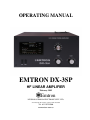
OPERATING MANUAL
EMTRON DX-3SP
HF LINEAR AMPLIFIER
February 2009
Emtron
DIVISION OF EMONA ELECTRONICS PTY. LTD.
92-94 Wentworth Avenue, Sydney 2010, Australia
Tel. +612 92110988
www.emtron.com.au
INITIAL SETTINGS FOR PLATE AND LOAD
CAPACITORS
TEST
BAND
FREQUENC
Y
FACTORY SETTINGS
USER SETTINGS
50 OHM LOAD
ANTENNA
PLATE
28.600 MHz
10m
24.900 MHz
12m
21.200 MHz
15m
18.100 MHz
17m
14.200 MHz
20m
10.125 MHz
30m
7.070 MHz
40m
3.600 MHz
80m
1.800 MHz
160m
1.850 MHz
160m
1.900 MHz
160m
LOAD
TABLE 1
(Also found in Chapter 10)
2
PLATE
LOAD
TABLE OF CONTENTS
1
GENERAL DESCRIPTION .................................................................................................................................................... 5
1.1
DX-3SP – INTERNAL VIEW .................................................................................................................................................. 6
2
TECHNICAL SPECIFICATIONS .......................................................................................................................................... 7
3
UNPACKING ............................................................................................................................................................................ 9
3.1
3.2
3.3
4
INSTALLATION ENVIRONMENT..................................................................................................................................... 10
4.1
4.2
5
10
CONNECTIONS TO TRANSCEIVER / EXCITER ....................................................................................................................... 13
EARTH AND MAINS CONNECTIONS ...................................................................................................................................... 13
TERMINATING THE POWER CABLE (EXPORT VERSION)........................................................................................................ 13
OPERATION AT 240V, 230V, 220V, 200V (EXPORT VERSION) ........................................................................................... 13
DX-3SP DESCRIPTION ........................................................................................................................................................ 15
8.1
8.2
8.3
8.4
8.5
8.6
8.7
8.8
9
POWER / EARTH CONNECTIONS .......................................................................................................................................... 12
RF CONNECTIONS ............................................................................................................................................................... 12
TRANSCEIVER CONTROL..................................................................................................................................................... 12
ELECTRICAL CONNECTIONS.......................................................................................................................................... 13
7.1
7.2
7.3
7.4
8
CONTROLS ......................................................................................................................................................................... 11
DISPLAYS ........................................................................................................................................................................... 11
REAR PANEL ......................................................................................................................................................................... 12
6.1
6.2
6.3
7
REQUIRED ENVIRONMENT .................................................................................................................................................. 10
POWER REQUIREMENTS ...................................................................................................................................................... 10
FRONT PANEL ...................................................................................................................................................................... 11
5.1
5.2
6
OPENING THE CARTON ......................................................................................................................................................... 9
OPENING THE DX-3SP COVER ............................................................................................................................................. 9
INSTALLING THE TRANSFORMER .......................................................................................................................................... 9
RF SECTION ....................................................................................................................................................................... 15
MAINS TRANSFORMER........................................................................................................................................................ 15
H. V. POWER SUPPLY ......................................................................................................................................................... 15
SOFT START MODULE ......................................................................................................................................................... 15
SENSOR MODULE ................................................................................................................................................................ 15
ANTENNA RELAY / QSK MODULE ...................................................................................................................................... 16
DISPLAY BOARD ................................................................................................................................................................. 16
CONTROL BOARD ............................................................................................................................................................... 16
POWERING UP...................................................................................................................................................................... 17
OPERATION....................................................................................................................................................................... 17
10.1 TUNING PROCEDURE ................................................................................................................................................... 17
10.1.1
General...................................................................................................................................................................... 18
10.1.2
Preliminary tuning .................................................................................................................................................... 18
10.1.3
Final tuning ............................................................................................................................................................... 19
10.1.4
Potential problems during tuning.............................................................................................................................. 20
10.2 USING YOUR DX-3SP .................................................................................................................................................... 20
10.2.1
CW / RTTY and all digital modes .............................................................................................................................. 20
10.2.2
Voice modes (SSB)..................................................................................................................................................... 20
10.2.3
Hints on good linearity and efficiency....................................................................................................................... 21
11
SWITCHING THE POWER OFF..................................................................................................................................... 21
3
12
TROUBLESHOOTING - IF SOMETHING GOES WRONG........................................................................................ 21
12.1
12.2
12.3
12.4
12.5
12.6
12.7
12.8
12.9
12.10
NO POWER .......................................................................................................................................................................... 21
FAN NOT WORKING............................................................................................................................................................. 22
IF THE FAULT LIGHT TURNS ON ........................................................................................................................................ 22
OVER-TEMPERATURE CUT-OFF ........................................................................................................................................... 22
OVER-CURRENT CUT-OFF ................................................................................................................................................... 22
IG2 BLINKS FAST - NO PLATE VOLTAGE .............................................................................................................................. 22
SPARKS / DISCHARGES IN RF AREA .................................................................................................................................... 23
SWR CUT-OFF .................................................................................................................................................................... 23
FREQUENT OVER-DRIVE PROTECTION CUT-OFF .................................................................................................................. 23
TUBE REPLACEMENT ...................................................................................................................................................... 23
13
WARRANTY / SERVICE .................................................................................................................................................. 23
14
GLOSSARY ......................................................................................................................................................................... 24
15
APPENDIX 1: SCHEMATIC DIAGRAMS ..................................................................................................................... 25
15.1 BLOCK DIAGRAMS ............................................................................................................................................................. 25
15.1.1
DX-3SP Block Diagram ............................................................................................................................................ 25
15.1.2
AC INPUT AND WIRING DIAGRAM....................................................................................................................... 26
15.2 CIRCUIT DIAGRAMS ........................................................................................................................................................... 27
15.2.1
SOFT START Single Phase – Circuit Diagram ......................................................................................................... 27
15.2.2
HIGH VOLTAGE POWER SUPPLY – Circuit Diagram .......................................................................................... 28
15.2.3
RF Module Simplified................................................................................................................................................ 29
15.2.4
RF output circuit ....................................................................................................................................................... 30
15.2.5
QSK – Circuit Diagram............................................................................................................................................. 31
15.2.6
RF Sensor .................................................................................................................................................................. 32
15.2.7
DISPLAY BOARD – Circuit Diagram....................................................................................................................... 33
15.2.8
CONTROL BOARD – Circuit Diagram .................................................................................................................... 34
15.3 CONTROL BOARD AND ADJUSTMENT POINTS..................................................................................................................... 35
15.3.1
Control Board Component Layout ............................................................................................................................ 36
15.3.2
Control Board – Solder Side Track work .................................................................................................................. 37
16
APPENDIX 2: WAVEFORMS .......................................................................................................................................... 38
16.1
16.2
17
QSK SWITCHING ............................................................................................................................................................... 38
LINEARITY ......................................................................................................................................................................... 38
APPENDIX 3: ADJUSTMENTS ....................................................................................................................................... 39
17.1 CONTROL BOARD ............................................................................................................................................................... 39
17.1.1
PRE-BIAS ADJUSTMENT ........................................................................................................................................ 39
17.1.2
BIAS ADJUSTMENT ................................................................................................................................................. 39
17.1.3
SWR PROTECTION ADJUSTMENT ........................................................................................................................ 40
17.1.4
EBS ADJUSTMENT .................................................................................................................................................. 41
17.1.5
SCREEN VOLTAGE ADJUSTMENT ........................................................................................................................ 41
17.1.6
SCREEN CURRENT LIMIT ADJUSTMENT............................................................................................................. 41
17.1.7
IPTRIP ADJUSTMENT ............................................................................................................................................. 42
17.2 DISPLAY BOARD ADJUSTMENTS ........................................................................................................................................ 43
17.2.1
PLATE CURRENT .................................................................................................................................................... 43
17.2.2
PLATE VOLTAGE..................................................................................................................................................... 44
17.2.3
REFLECTED POWER .............................................................................................................................................. 44
17.2.4
FORWARD POWER.................................................................................................................................................. 44
17.2.5
SCREEN CURRENT.................................................................................................................................................. 44
17.3 RF SENSOR (BRIDGE) ADJUSTMENT................................................................................................................................... 45
DX-3SP LINEAR AMPLIFIER
Serial No
…………
OPERATING MANUAL
January 2009
CAUTION
The DX-3SP has been designed for 100% safe operation and long life. Interlocking
sensing circuitry constantly monitors conditions inside the amplifier. It must be
noted however, that the high voltages present inside the DX-3SP are
EXTREMELY DANGEROUS. Do not remove the top cover under any
circumstances if any leads are still plugged into the rear of the amplifier especially if the AC lead is plugged in the power outlet. Before any component
inside the high voltage, power supply or output section is touched,
unplug all rear panel leads and allow at least 5 minutes of 'off time'.
After that, you should further check this by momentarily shorting the tube anode
to the chassis with a suitable insulated lead.
1 GENERAL DESCRIPTION
The Emtron DX-3SP Linear Amplifier is a 4000 watt average output power, for the 160m through 10m
amateur bands (9 bands), housed in a desk-top cabinet with self-contained power supply and cooling system.
It utilises a two high performance tetrodes, type FU-728F, a ceramic metal tube with a plate dissipation of
1500W. The tubes are air cooled by a commercial grade forced air turbine blower system and two extra
suction fans above the tube.
Tetrodes offer exceptionally stable operation and levels of quality performance far exceeding that which can
be expected from triodes. The harmonic output and intermodulation distortion achieved with this tube are
exceptionally low. This is especially important when dealing with a high output power.
The Emtron DX-3SP is supplied as standard with a host of features including solid state metering and
comprehensive protection systems.
In addition, a unique Emtron QSK module is available as standard. With this installed, extremely rapid
switching times between transmit and receive are possible, with consequent advantages when using CW or
the digital modes.
Operation of the DX-3SP is greatly simplified by the absence of meter switching and of front panel level
setting controls. The front panel moving LED display systems indicate simultaneously: the output forward
and reverse power, screen grid current (positive and negative), the plate voltage and the plate current, while
5 single LED’s indicate: Ready, Overdrive warning, High SWR cut-off indication, On Air and Fault.
The Emtron Electronic Bias Switch (EBS) automatically switches the standing current (typically 0.5 A) off
when there is no modulation. This reduces the average tube dissipation.
On initial switch on, the unique Emtron "soft start" circuitry ensures that no damaging AC surge currents are
generated.
Professional, fine output tuning adjustment is possible, due to the 6: 1 reduction mechanism fitted.
5
1.1 DX-3SP – Internal View
The main components of a DX-3SP amplifier are shown in the picture below.
BLOWER
Mains Isolation
Relay
ANT. RELAY
(QSK)
SOFT START
CONTROL
BOARD
Coupling
Capacitor
RF SENSOR
RF CHOKE
Temperature Sensors
TERMINAL BLOCK
PRIMARY WIRING
HIGH VOLTAGE
POWER SUPPLY
MAINS
TRANSFORMER
SUCTION
FAN
SAFETY
MICORSWITCH
Tetrode FU-728F
TANK COIL, 10-30 m
SAFETY CHOKE
TANK COIL, 40 -160 m
DISPLAY
BAND SWITCH
POWER ON / OFF
STANDBY / OPERATE
SWITCH
BAND
SELECTOR
PLATE
TUNING
LOAD
TUNING
Figure 1
6
2 TECHNICAL SPECIFICATIONS
FREQUENCY COVERAGE: Complete (manually tuned) coverage of the nine HF amateur bands:
1.800 – 2.000 MHz
3.500 – 4.000 MHz
7.000 – 7.500 MHz
10.000 – 10.300 MHz
14.000 – 14.350 MHz
18.000 – 18.500 MHz
21.000 – 21.500 MHz
24.000 – 24.500 MHz
28.500 – 29.990 MHz
TRANSMITTING MODES: The DX-3SP supports SSB, CW, AM, FM, RTTY and SSTV.
OUTPUT POWER: Typical 4000 watts carrier or up to 5000 W PEP
DUTY CYCLE: Suitable for SSB operation.
CW: 4 minutes transmit, 1 minute receive.
AM: 3 minutes transmit, 1 minute receive.
DRIVE POWER: Nominal 60-90 watts for full rated output.
INPUT IMPEDANCE: Nominal 50 ohm passive impedance, unbalanced. VSWR 1.4:1 or less.
OUTPUT IMPEDANCE: Nominal 50 ohm passive impedance, unbalanced. VSWR 2.6:1 or less.
DISTORTION: Third order intermodulation products are more than 35 dB below rated output.
HARMONICS: Harmonic output is better than 50dB below the rated output.
FAULT PROTECTION: The comprehensive fault protection system includes circuitry to monitor:
•
plate current: should the plate current exceed a safe value, the amplifier goes to standby for 2 minutes.
The nominal trip plate current is 2.5 A
•
screen grid over-current: Absolute tube protection is offered with visual warning and a reduced power
level being enabled if the screen current exceeds a pre-set limit.
The screen current is limited to about 50 – 60 mA total, for the 2 tubes.
•
temperature: Should the tube's temperature exceed a specific level, amplifier operation is suspended
until the temperature drops to a safe level.
The cut-off temperature sensor has a nominal value of 110° (230F).
The fan speed control temperature sensor has a nominal value of 80° (176F).
OPERATIONAL PROTECTION
•
Overdrive protection: Should the DX-3SP be overdriven, a LED warning indicator will light up when
the linearity limit is reached. If the drive is increased further, a 2 second cut off (by-pass) will follow.
•
SWR protection: Should the DX-3SP sense an SWR exceeding 2.6:1, a LED warning indicator will
light up, simultaneously with a 3 second cut off.
7
METERING: The front panel moving LED display systems indicate:
“Moving light” LED indicators:
•
output power
•
reflected power
•
screen grid current (positive / negative)
•
plate voltage
•
plate current
Five single LED’s:
•
on air
•
ready
•
fault
•
overdrive warning
•
SWR cut-off indicator
EBS: Electronic Bias Switch - automatically switches the standing current (about 0.5 A) to a lower ("prebias") value - when there is no input drive.
PRE-BIAS: A small current will flow in the tube when the amplifier is keyed on, but there is no modulation.
This will prevent a harsh sound at the beginning of each word, when the EBS is activated and the tube goes
through a non-linear zone, before reaching the correct initial bias.
The nominal Pre-Bias current is 40 mA (30 to 60 mA, not critical).
QSK: makes possible the antenna switching at very fast rate - typically 3ms switching time in each direction.
SOFT START: when switched on, the mains power is gradually applied to the transformer, over a period of
about 5 seconds, to avoid the high in-rush current typical for such high loads.
Typical voltage drop on the triac: 1 V when not transmitting, <2 V at full power.
PTT Switching: Open circuit voltage +6 VDC. Ground to key (6 mA to ground).
COOLING: Two speed forced air cooling.
OPERATING TEMPERATURE: 0 to 40° Celsius
FUSING: Two 40 A normal acting fuses in each mains line on the rear panel.
OPERATING MAINS VOLTAGE: 200 to 240 V, Single Phase (Transformer taps: 200, 220, 230, 240 V).
Optional 400V, power between 2 mains phases.
CURRENT CONSUMPTION: about 35 ARMS when transmitting full power at 240 V mains.
DIMENSIONS: 470 mm wide, 250 mm high, 470 mm deep (18.5” x 10” x 18.5”)
WEIGHT: 55 kg (120 lb) unpacked (with the transformer installed)
TRANSFORMER: shipped separately in a wooden box approx. 310 x 250 x 260 mm (12” x 10” x 10.25”),
30 kg (66 lb).
8
3 UNPACKING
The DX-3SP is packed in a heavy duty package easily sufficient to protect the amplifier during transportation,
even in case of fairly rough handling. The weight of the mains transformer does mean, however, that dropping
the amplifier would without doubt result in some damage when the transformer is installed inside.
3.1 Opening the carton
When opening the packing, do not cut the carton. Save the packing material for possible further re-use.
Shipment of your DX-3SP in other than factory packing may result in non-warranty damage.
3.2 Opening the DX-3SP cover
Remove the 4 screws on each side and remove the cover. An inspection of the interior of the amplifier should
reveal no damage or adversely affected components. Should there be any form of problem, notify your
supplier immediately.
3.3 Installing the transformer
Make sure the transformer is wired for the nominal mains voltage in your area. See 7.4.
Two people are needed to install the transformer. The best is to put the DX-3SP on a flat, smooth surface such
as a bench or a table-top, covered by a small carpet of a folded blanket, so that it can be moved by sliding it
on the table. Locate the cover micro-switch and temporarily tape the micro-switch down to avoid damage to
the sense wire during transformer installation.
Lift the transformer and lower it into the chassis, positioned with the 12-pin connector towards the front of the
amplifier. Put the transformer in at a slight sidewise angle, while taking care that it does not touch the sections
of the wire loom between the control board and the front panel display. Mind also the micro-switch, the front
panel switches and the control board at the back. See pictures below.
Connect the
transformer
primary here
Mind the control board,
Wire loom
Microswitch
Display & switches
Figure 2
9
Move the transformer close to the front panel (do not slide it – lift it and move). This will create more space at
the back, so that the high voltage wires can be connected. Plug the two wires from the high voltage power
supply into the 2 pins at the lower part of the transformer. Connect also the 4-way connector and the orange /
black wire. The mating single wire comes from the blower mounted relay and it is orange / black. It is the
only single wire that will mate with the connector. See Fig. 3 below.
Connect the high voltage wires
Connect the 4-way connector
and the single wire (O/B).
Figure 3
Move the transformer to the middle position, trying to line up the holes in the transformer with the holes in
the chassis. When the holes line up, pull the amplifier so that it overhangs, about 1/3 on the desk and 2/3 out.
Make sure somebody is helping during this operation. The back of a chair of suitable height can be used to
help support the amplifier, but make sure someone else is holding it firmly in position. Insert the screws and
washers from underneath. When all 4 screws are in, tighten them firmly using a large size Philips screwdriver.
Plug in the 12-way connector.
Connect the 2 mains wires to the terminal block of the soft start module. See pictures, Fig.1, Fig.2.
Remove the tape securing the cover interlock switch down before installing cover. Put the cover back and the
installation is complete.
4 INSTALLATION ENVIRONMENT
4.1 Required environment
The DX-3SP amplifier can be operated at an ambient temperature between 0 and 40° Celsius. It should be
installed in a place with good ventilation and protected from the direct sunlight. At least 5 cm (2”of free space
must be left at the left and right of the amplifier for ventilation. Do not place any object on top of the
amplifier, especially above the ventilation opening.
An environment free of dust, smoke and high humidity is required, as for any high powered RF amplifier.
Dust or particles resulting from burning fire wood or coal could be responsible for sparks or electrical
discharges between the capacitor plates, or in other parts of the RF section.
4.2 Power requirements
Single phase, 200, 220, 230 or 240 Vac nominal or 400 Vac (special order)
When operating at full power, up to 37A from the 200 VAC mains is required (even more if tuning is not
correct). Ensure that the AC supply you intend to use is fully rated and properly fused. The Emtron "soft
start" circuitry ensures that there are no momentary surges of current at power-up; therefore the fuse does not
need to be over-rated. However, the wiring of the mains supply for the amplifier should be able to handle the
power at full load with minimal drop in the voltage, to insure the performance of your DX-3SP does not
suffer.
10
5 FRONT PANEL
The following controls and indicators are present on the front panel:
5.1 Controls
BAND SWITCH
A nine position switch selects the desired frequency range. The operating bands are indicated in metres.
PLATE TUNE
Tunes the amplifier operating frequency. A chart of approximate starting settings is given in Table-1
LOAD TUNE
Tunes the amplifier output loading. A chart of approximate starting settings is given in Table-1
ON/OFF
Switches the AC power on and off. On initial switch on, the standby mode is enabled. Note also the
appropriate switch down sequence, given in Section 11.
OPR/STBY
Enables the amplifier once it has warmed up. In STANDBY mode, the screen voltage is removed and any RF
power applied to the input is bypassed to the output. If this switch is changed to OPERATE before the
READY light comes on, the FAULT light will turn on. This is not a fault, but it is better to leave the switch in
STBY position until the amplifier is ready to operate.
5.2 Displays
All the DX-3SP indicators are concentrated in a single, “moving light” display (See Fig. 4). The following
values are displayed (top to bottom):
Output Power - Scale up to 5 kW, non linear.
Reflected Power - Scale up to 500W, non linear.
Plate Voltage - Scale up to 3.5 kV
Ig2 - Zero-centered display. Green: full scale 80 mA reverse screen current. Red: full scale 50 mA of positive
screen current. Above this value, the red LEDs will flash, warning to increase the loading, or reduce the drive.
Plate Current - Scale up to 3.2 A.
RF OUTPUT POWER (kW)
OVER
DRIVE
REFLECTED POWER (W)
SWR
Ig2
ON AIR
PLATE VOLTAGE (kV)
READY
PLATE CURRENT (A)
FAULT
Figure 4 Front Panel Display
11
ON Air - single LED, green. When pressing PTT, this LED turns on (while in OPERATE and READY).
READY - single LED, yellow. Turns on at the end of warm-up period, when the mains power to DX-3SP is
switched on. It turns off for about 2 minutes if the plate current protection is triggered. In this case, the
FAULT light also turns on. It turns OFF while in an SWR Fault condition or over-temperature Fault.
FAULT - single LED, red. Turns on in 3 situations:
•
when the over-temperature protection is triggered, the FAULT turns on until the tube cools to a safe
level. During this time, the operation of the amplifier is disabled, the screen voltage is off and any RF
power applied to the input is bypassed directly to the output. The READY light is also off.
•
when the over-current protection is triggered, FAULT turns on for 2 minutes, while READY turns off.
•
at DX-3SP power up, if the OPR/STBY switch on the front panel is left in OPR position. The FAULT
light will go off when the DX-3SP is ready for operation, after warm-up.
SWR - single LED, red. A three second cut-off will happen if your antenna has a SWR worse than 2.6:1 at
the operating frequency. During the cut-off, the RF from the input is directly by-passed to the output.
OVER-DRIVE - single LED, yellow. Flashes when the input drive is exceeding the linear operation level. If
even more drive is applied, the overdrive protection will cut off the operation for about 2 seconds.
NOTE: the input drive for the indicator to turn on depends on a certain extent on the tuning of the amplifier.
6 REAR PANEL
The following connectors and controls are present on the rear panel
6.1 Power / Earth connections
A wing-nut Earth connection is provided at the rear of DX-3SP. A good Earth link must be provided here.
Connect this first, before making any other connection to the amplifier. Two fuse holders are fitted along with
40A, normal acting fuses.
6.2 RF connections
RF INPUT
The RF input is an SO-239 female connector. A 50 ohm coaxial cable line of good quality terminated with a
PL-259 coaxial connector is required to connect the transceiver or exciter output to the input connector of
your DX-3SP amplifier.
RF OUTPUT
The RF output is also a female SO-239 connector. The use of a high quality RG-8A/U, RG-213 or similar 50
ohm coaxial cable line terminated with a ‘VHF’ type PL-259 connector is essential. Similarly, a VSWR of
2.6: 1 or better is mandatory. Remember too, that the EMTRON DX-3SP amplifier can deliver 4000 W
continuously and up to 5000 W PEP in the SSB mode. Not all antennas can handle such power.
6.3 Transceiver control
PTT
The PTT input is a female RCA connector. This line controls the transmit / receive switching system. This
jack must be connected to transceiver or exciter relay contacts which are open on RECEIVE and closed on
TRANSMIT.
The PTT input presents an open circuit voltage of + 6V with respect to the chassis. A current of 6 mA must
be switched by the transceiver or exciter.
12
7 ELECTRICAL CONNECTIONS
7.1 Connections to Transceiver / Exciter
Signal connections
Before making any connections, ensure that DX-3SP is not connected to AC power, and the transceiver is not
transmitting. Connect the antenna first to the DX-3SP output. Then connect the transceiver output to the DX3SP RF input. Plug the PTT lead into the RCA socket marked PTT on the rear panel.
The most appropriate interconnection layout is shown in Figure 5 below. In this set-up, the transmit/receive
relays in the DX-3SP are controlled directly by the transceiver or exciter.
TO ANTENNA
EMTRON
DX-3SP
RF
OUT
RF
IN
RF
OUT
PTT
Relay
Input
ALC
ALC
Station
Transceiver
PTT
Relay
Output
(Optional)
Figure 5 Connections between DX-3SP and Station Transceiver
7.2 Earth and mains connections
Power connections
Before connecting any power to the amplifier, make a good Earth connection to the screw with wing nut at
the rear of DX-3SP. Terminate the power cable if necessary (export versions). Check that the transformer tap
corresponds to the nominal local mains voltage. Make sure the POWER switch on the front panel is in the
OFF position. Then plug the power cable into the power outlet.
7.3 Terminating the power cable (export version)
As different countries have different standards for their power connections, the DX-3SP amplifiers exported
from Australia are supplied with an un-terminated power cable. The green / yellow wire is connected to the
amplifier chassis and MUST be connected to the safety ground of the AC mains supply. It must NEVER be
connected to one of the AC “hot” wires or to the Neutral wire.
IN THE U.S.: The Brown and Blue wires connect to the mains transformer inputs. Brown wire is to be
connected to AC line 1 and Blue wire to AC line 2. Both lines are fused.
IN OTHER COUNTRIES: The brown wire is to be connected to the LIVE or ACTIVE line. The blue wire is
to be connected to NEUTRAL.
7.4 Operation at 240V, 230V, 220V, 200V (export version)
The Emtron DX-3SP will normally arrive pre-set for the power source of the country the amplifier has been
sold to. However if operation to another mains voltage is required, the appropriate connection changes will be
needed.
Figure 7 shows the transformer connections for 200V, 220V, 230V and 240V operation. If a change is
required, this should be done only by a qualified technician, after taking all the necessary safety precautions.
See CAUTION on page 5.
To change the transformer tap, a single brown wire has to be unsoldered and moved to the new tap. See below
13
PLEASE NOTE: The DX-3SP should not be connected to a mains supply of less than 200VAC!
Move the thick brown wire to 240, 230,
220 or 200V.
Leave the thin brown wire on 240V
Figure 6 Wiring for 230V shown as example
240
0
240V:
0
200
FAN
220
230
240
230
230V:
0
200
FAN
240
220
220
220V:
0
FAN
200
220
230
240
200V:
0
FAN
200
220
Figure 7 TRANSFORMER AC INPUT CONNECTIONS
14
230
240
8 DX-3SP DESCRIPTION
8.1 RF Section
The RF section occupies the right hand side of the DX-3SP (looking from the top - front). See picture in 1.1.
RF Switch and tuned circuits
At the front of the amplifier are two variable capacitors, for plate and load tuning. A 9-position ceramic
switch is employed for the 9 operating bands. Next to the switch is the 40 to 160 metre tank coil (torroid). The
silver plated, large diameter copper tube is the 10 to 30 metre tank coil.
RF Sub-chassis
The FU-728F tubes are positioned on a separate RF sub-chassis. All the connections to the tubes, except for
the plate, are under this sub-chassis. A 9-way heavy duty connector is used for the outside connections. The
fan blows air into this sub-chassis, which is forced out through the ventilation fins of the tubes. The air
temperature is sensed by sensors placed above the tubes. The sensors must stay in a position close to
horizontal. Make sure they are not pushed down, too close to the tube, as high voltage exists between them.
The plates are connected to the RF network and to the choke supplying the 3400VDC voltage to the plate of
the FU-728F tubes. Above the tubes there is one fans sucking air and reducing the back pressure to the
blower.
8.2 Mains transformer
The transformer is the heart of the amplifier, a high performance type, designed to reduce the size and weight.
It is built with a generous reserve of power, handling easily the DX-3SP requirements in heavy duty
operation. The primary can be wired for 200VAC, 220VAC, 230VAC or 240VAC operation. See Figure 7.
There are several secondary windings, as follows:
•
Filament supply (9 Vac)
•
Low voltage supply to the controller board (10 Vac)
•
QSK module supply (27 Vac)
•
Bias supply (110 Vac)
•
Screen grid supply (295 Vac)
•
High voltage supply (2400 Vac)
8.3 H. V. Power Supply
A full wave bridge rectifier and filter converts the high voltage AC into high voltage DC with a huge reserve
capacity of 58 microfarads.
8.4 Soft start module
At power up, the mains power is gradually applied to the transformer by the soft start module. The power is
gradually applied over a time of about 5 seconds, avoiding the high inrush current typical for such big loads.
8.5 Sensor module
A small metal box positioned at the output of the DX-3SP. It detects the forward and reverse power, for
measurement and display.
15
8.6 Antenna relay / QSK module
The QSK module acts as an antenna relay controlled by the transceiver, via the control board. It switches the
antenna between the transceiver, during reception, and amplifier, during transmission. It is also used to bypass
the RF from the transceiver, directly into the antenna, when the amplifier is in standby mode, or during
special conditions like overdrive, bad SWR or other error conditions.
The QSK is a module with two very fast, high power vacuum relays, and the control circuitry. The purpose of
QSK is to allow very fast switching between transmit and receive, during digital communications. See
Appendix 2 showing oscilloscope displays of fast switching times and contact bounce-free operation of the
QSK module.
8.7 Display board
This board has a number of inputs where various voltages are connected. The board converts these voltages
into a "moving LED" type of display. Two of these displays have flashing light indication (Ig2+ and plate
current).
8.8 Control board
The brain of the amplifier is the Control Board. The following circuitry is part of this board:
•
Bias voltage regulator, also incorporating a sensitive grid current detector for overdrive detection.
Adjustable pre-bias, removes the distortion at the beginning of the word, when EBS is activated.
•
Screen voltage regulator, with adjustable voltage and adjustable current limiting, for tube protection.
•
Overdrive protection and timer - based on detecting grid current, it initially gives visual warning and,
at higher level of overdrive, it cuts off the amplifier for 2 seconds. It ensures a clean signal, making
it virtually impossible to overdrive the DX-3SP.
•
SWR detector and timer - switches the amplifier to bypass mode for about 3 seconds when high SWR
is detected. Adjustable SWR level. Factory adjusted to about 2.6 : 1
•
EBS - the Electronic Bias Switch - senses the presence of RF input power and turns on the bias to start
transmission. Factory adjusted for about 0.5W. When the input power exceeds this limit, the plate
current starts flowing. When there is no speech, even for a very short time, the tube dissipation is cut
to a low value, as set by the pre-bias adjustment.
•
Interlocking, timer for filament warm-up
•
Relay control: ready relay, SWR relay, over-drive relay, antenna relay
•
QSK switching control
•
Display control: Ig2 measurement and display, SWR cut-off display, overdrive warning display,
READY display, FAULT display
•
Logic circuitry, two low voltage supplies to the various electronic circuits
16
9 POWERING UP
Before switching the power on, check all the necessary connections: Earth, Antenna, Transceiver, PTT. Make
sure the 2 switches on the front panel are in the positions: OFF, STBY.
Switch now the mains power ON (The power switch to ON position). The "soft start" system will take about 5
seconds to fully turn the power on. SWR light will turn on briefly, then off. Wait for the DX-3SP to warm up,
until the READY light turns on.
This takes about 2 - 3 minutes.
WARNING !
WHEN YOU SWITCH THE POWER ON, YOU MUST HEAR AIR FLOW NOISE.
IF THERE IS NO AIR FLOW NOISE, SWITCH THE POWER OFF IMMEDIATELY
AND CONTACT YOUR SUPPLIER.
10 OPERATION
10.1 TUNING PROCEDURE
INITIAL SETTINGS FOR PLATE AND LOAD
CAPACITORS
TEST
BAND
FREQUENC
Y
FACTORY SETTINGS
USER SETTINGS
50 OHM LOAD
ANTENNA
PLATE
28.600 MHz
10m
24.900 MHz
12m
21.200 MHz
15m
18.100 MHz
17m
14.200 MHz
20m
10.125 MHz
30m
7.070 MHz
40m
3.600 MHz
80m
1.800 MHz
160m
1.850 MHz
160m
1.900 MHz
160m
LOAD
PLATE
TABLE 1
For convenience TABLE 1 has been also reproduced on the front inner cover
17
LOAD
10.1.1 General
For each band and operating frequency, the transceiver settings must match the position of the BAND switch on
the front panel of the DX-3SP, while the PLATE and LOAD knobs must be adjusted for optimum operation
which gives – in conjunction with the input drive level, the maximum output power that can be obtained for that
input power.
When the tuning is correct, this will also result in a minimum plate current, minimum plate dissipation and good
linearity.
10.1.2 Preliminary tuning
•
Turn the BAND switch to the same band setting as the transceiver.
•
Put LOAD and PLATE knobs in the initial positions given in Table 1.
•
DX-3SP must be powered ON and "Ready", with the OPR/STBY switch in OPR position.
•
Start with the transmitter at minimum power, in a "carrier" mode e.g. RTTY or CW - key down.
•
Key the transceiver ON and gradually apply power to the DX-3SP. When 0.5 to l W of drive is reached,
the EBS is activated and the plate current jumps from zero to about 0.5 A.
•
Increase the drive until there is some output power indicated. If the current plate Ip reaches about 1 A
and there is still no output indication, turn PTT off and check the connections, the band and the initial
settings.
•
As soon as there is any power indication, tune PLATE for maximum output (and minimum plate
current).
•
Apply more drive and adjust PLATE again for maximum output. Keep PTT ON for short time only
(about 10 seconds). Go gradually, in several steps. When about 1000W output is reached, adjust LOAD
for maximum output. At low and medium power Ig2 indication will be green (the screen current is
reverse, or negative). While tuning try to minimise this green indication.
•
At high power the Ig2 indication is red (normal, or positive screen current). If there is no red Ig2
indication, it is likely that LOAD needs to be turned clockwise, towards higher numbers on the dial.
While tuning, try to maximise the red Ig2 indication.
•
Apply more drive and adjust both knobs again. When screen current is too high (flashing red Ig2
indication), increase loading by turning anti-clockwise the loading knob. (LOAD towards lower numbers
on dial) until Ig2 drops almost to zero. Then adjust PLATE for maximum output power and maximum
Ig2. At this point, Ig2+ is the most sensitive indicator of resonance on the working frequency. If Ig2
goes too high (e.g. starts blinking), increase the loading again, then tune PLATE.
•
Repeat the above steps, while gradually increasing the input drive power, until the overdrive indicator
just starts turning on. Now the DX-3SP is tuned for operation at full power on that particular operating
frequency.
NOTES:
1. The maximum power is obtained from a DX-3SP when:
onset of the overdrive indication
PLATE is tuned for maximum output power, maximum screen current Ig2 and minimum plate current,
Ip
Ig2 indicator shows 2 to 4 red LEDs (depending on frequency and load, sometimes Ig2 is very low, 1
LED or no indication at all).
2. The above conditions will also give the best linearity.
18
3. During the preliminary tuning, switch PTT on and off several times, to allow time for tube cooling. The tube
dissipation (at a given drive level) is minimum when tuning is optimum. In short, be brief, with tuning "bursts".
4. Preliminary tuning, as described above, is only necessary when operating for the first time in a certain band.
When the final settings for PLATE and LOAD have been found for the particular working conditions especially the antenna used, note your settings on Table 1. The new settings will normally differ to some extent
from the ones indicated, depending on the “resistance and reactance" of your antenna load.
5. If less than maximum power is run, it is possible that the Ig2 indication remains green and never goes into
red.
10.1.3 Final tuning
Once the preliminary tuning has been done for each band / antenna combination, the values found for PLATE
and LOAD can be used for final tuning, with no need to repeat the preliminary tuning every time.
Tuning for full power
•
Start with low drive level and the PLATE and LOAD knobs in the known initial positions.
•
Put PTT ON and increase the power (fairly quickly), to the onset of the overdrive indication. If the
screen current (red Ig2) goes too high, adjust LOAD, by turning the knob to the left – towards lower
numbers on the dial (increasing the load).
•
Adjust the drive level and LOAD until the overdrive indicator is just about to turn ON, and at the same
time Ig2 shows two or three red LED's ON.
•
Fine tune PLATE for maximum output and maximum Ig2. Repeat the step above if required.
•
When the desired tuning level is achieved on a band, record the plate and load numbers in the ‘Users
Settings’ of Table 1.
NOTE: A flashing red Ig2 indicator, even for a long time, is not harmful to the tube, since Ig2 is limited to a
safe value.
Tuning for less than full power
NOTE: Low output power could create more tube plate dissipation then the normal / full output.
•
Start at low power, with the initial values for PLATE and LOAD
•
Put PTT ON and apply drive until the output is about 1/2 of the desired power.
•
Adjust LOAD for maximum output. Most likely, the knob will have to be rotated clockwise, towards
higher numbers on the dial.
•
Adjust PLATE for maximum output
•
Apply more power
•
Repeat the 3 steps above until the required power is achieved. If screen current is indicated by Ig2, it
should display two to four red LED's. Maximise this Ig2 indication (and the output power at the same
time), by tuning PLATE
Please note that the tuning at lower power is different from the setting at full power (especially LOAD).
•
If the output goes higher then desired, reduce the drive and re-tune. Never reduce the output by detuning the amplifier!
NOTE: If the output is low (say, less than about 2000W), Ig2+ will never show any screen current at all. Ig2
might even indicate a negative current, in green - this is normal and is no cause for concern.
19
If there is green Ig2- indication, for a given input drive, try to minimise it and even to obtain red indication. For
this, it is likely that LOAD needs to be moved clockwise, followed by PLATE retuning. If red indication is
achieved, try to maximise it by tuning.
With low drive / low output it is likely the Ig2 indication to be green, increase as more drive is applied, then
decrease and become red at higher output.
10.1.4 Potential problems during tuning
The tuning operation should be completed fairly quickly. If the tuning process takes a longer time, it should be
done by switching the transmission on and off several times, to allow the tube time to cool.
•
If the FAULT light comes on, it is possible that the plate current has reached too high values due to
incorrect plate tuning. In this case, reduce the excitation power, wait for the FAULT light to turn off
(about 2 minutes) and resume tuning.
•
If the overdrive protection is activated, by cutting off the amplifier for 2 seconds. It is likely in this case
that you are applying too much power at the input. Reduce the power and watch the "overdrive" LED.
Increase the power only until this light starts flashing.
•
If the overdrive protection is activated at low power – this could be due to incorrect loading. Turn the
LOAD control clockwise and tune PLATE. Increase the drive and repeat in small steps.
•
If the SWR protection cuts in – it is likely to be a problem with either the feedline, antenna or associated
antenna switching components. In principle, the SWR protection level in DX-3SP is adjustable, but it is
far preferable for you to fix your antenna system.
10.2 USING YOUR DX-3SP
While tuning and adjusting the amplifier, a CW mode is normally used. When these operations are finished, you
can change to the operating mode you wish to use and start operating.
10.2.1 CW / RTTY and all digital modes
In CW, the setting up of the amplifier is similar to that of the tuning mode. After adjusting the input power level
to the amplifier, according to the desired output level, and tuning the plate and load capacitors, you can simply
start operating by applying the same carrier level as during tuning. If the amplifier is set to deliver full output
power, or close to, then screen current will be present (red Ig2). As in the case of tuning, the best operation is
achieved when there is a certain amount of screen current flowing, corresponding to two to four red LED's
turning on in the Ig2 display.
10.2.2 Voice modes (SSB)
When a voice modulation is applied to the amplifier, the drive level is not precisely defined, as in the case of
tuning with continuous carrier. If there is screen current flowing, or an input overdrive, they will be indicated
only at peak of modulation, by the respective indicators flashing. The Ig2 indicator is likely to flash both green
and red. You will have to adjust the microphone gain, or the RF drive, or both, in an attempt to achieve peak
input driving conditions similar to those you have used while tuning. Occasional flashing of the overdrive
indicator is acceptable. If the over-driving is severe, a momentary cut-off will occur.
20
10.2.3 Hints on good linearity and efficiency
Operating with good efficiency: If you are watching the plate current indicator, you must be aware that the total
power the amplifier is drawing from the mains is proportional to the plate current. Power that is not sent to
antenna is dissipated by the tube. As explained in the Tuning section, the best tuning achieves a maximum
power output at the same time with a minimum plate current, drastically minimizing the tube dissipation. Be
aware that at a low power level, slightly different tuning is required than is for full power.
Achieving the best linearity: The amplifier must be tuned and operated all the time in the linear mode. This is
important because a non-linear operation will generate harmonics which will disturb RF communications in
other bands and frequencies.
We must distinguish two situations:
Less than full power.
With less then full power (say 3000W or less), correct tuning and no input overdrive indication, you will always
have your DX-3SP operating with a good linearity and clean signal.
Full power operation.
At full power, there are two things that must be watched to see when you reach the limit of linear operation: the
screen current, Ig2, and the grid current, indicated by the "Over-drive" LED.
In this case a good linearity is maintained up to the moment when the screen current is approaching the full
scale value of the Ig2 indicator and it starts flashing, or when the overdrive indicator fully turns on.
A high screen current, indicated by 4 LED's on in the Ig2 display, will create a moderate level of distortion.
Even a small amount of grid current will cause severe distortion. When the "Over-drive" indicator just begins to
turn on, there is a very small amount of distortion, created by a grid current of about 150 microamperes.
With this indicator flashing, you are at the limit of the RF carrier clipping. This is probably more acceptable in a
voice mode of operation. In CW or digital modes, the best is to slightly reduce the drive, just below this level. A
severe level of over-driving is not possible anyway, due to the cut-off protection. The cut-off will happen at
about 200 microamperes of grid current. See Appendix 2: Waveforms - and Section 12: Troubleshooting for
oscilloscope displays showing examples of a two tone generator driving the DX-3SP in linear mode.
The Ig2 indicator should have three to four LED's flashing ON at peak of modulation. This (combined with a
correct plate tuning), indicates an optimum loading, good efficiency and good linearity. A lower screen current,
due to excessive loading, will reduce the output power, with an equal amount of extra power dissipated by the
tube. A higher screen current, making all four LED's in the Ig2 flashing, will increase the distortion.
11 SWITCHING THE POWER OFF
When you have finished using the amplifier and you want to switch it off, the following procedure is
recommended: Stop transmitting. Put the switch on STBY. Leave the DX-3SP running idle for a few minutes, to
cool the tubes, and then switch the power off.
12 TROUBLESHOOTING - If something goes wrong
12.1 No power
When you switch on a DX-3SP, it takes about 3 - 5 seconds for the lights on the front panel display to come on.
This is due to the "soft start" circuit. If nothing happens after turning the power on, switch off at the front panel,
then check the following:
make sure the power point has power
make sure the power plug is fully pushed in into the power outlet
21
If it is still not working, unplug the power cord from the mains, then remove the fuses from the fuse holders on
the rear panel of DX-3SP and check them with an ohmmeter. If a fuse is blown, replace it with a fuse of the
same type and try again. If the fuse blows again, or if the fuses were not blown in the first place, contact your
supplier.
12.2 Fan not working
As soon as you switch the power on, you should notice two things about your DX-3SP: the display should
indicate about 3000V of plate voltage and you should be able to hear the fan running. The amplifier is not
supposed to be powered without the fan, even in idling mode. If the fan does not operate when you power up, or
if it stops while using the amplifier, switch the mains power off immediately and contact your supplier.
12.3 If the FAULT light turns on
The FAULT (red) light turns on in two situations:
Over-current in the plate circuit
This could happen due to a flash-over in the tube, or as a result of a momentary high plate current during tuning.
This completely disables the amplifier for about 2 minutes. The same timer is activated as when the amplifier is
switched on, causing the READY light to turn off. If the OPR/STBY switch on the front panel is put on STBY,
the FAULT will turn off, but the READY will be also off. When the READY comes on again, the FAULT will
disappear (if the amplifier was left in OPR), and the DX-3SP is ready to operate again.
Over-temperature cut-off. See below.
12.4 Over-temperature cut-off
The operation of the amplifier is disabled, but the timer is not activated. The READY light turns off, and the
FAULT light turns on. When the tube cools down, the FAULT turns off and the operation can resume. This type
of fault should never happen. DX-3SP has a very efficient air cooling system. When the ventilation is not
restricted, in normal ambient conditions, when properly tuned, a DX-3SP can operate at full power for extended
periods of time, with the fan not even going to high speed. The temperature cut-off happens when the tube
reaches 150º Celsius, with ample safety margin to the specified limit of 200º for the FU-728F tubes.
12.5 Over-current cut-off
If the plate current exceeds even for a brief time a pre-set safe limit, an over-current detector will activate the
power up timer, disabling the amplifier for about 2 minutes. During this time the READY light is off, and the
FAULT light is on, if the amplifier is left in OPR mode, as explained under 12.3, "If the FAULT light turns on".
12.6 Ig2 blinks fast - No plate voltage
If the high voltage is lost due to a fault in the amplifier, the screen current tends to reach very high values. This
is an unlikely situation, but if did happen, this would normally guarantee a tube failure in unprotected amplifiers
that do not have a current limiting circuit. The screen current limiting in DX-3SP is so efficient, that the tube is
fully protected even in such a situation and test bench DX-3SP's have been extensively run with no plate voltage
and maximum screen voltage, with no effect on the tube. If this loss of high voltage should happen to your
DX-3SP, the Ig2 display will have the red LEDs flashing, due to the screen current exceeding the pre-set limit,
with no input power applied to the amplifier, while switched to OPR.
22
In such a case, it is possible that the high voltage is still shown on the meter, but it does not reach the tube. In
any case, this is a major fault. Put the amplifier on STBY and the flashing will stop. Then switch the power off
and contact your supplier.
12.7 Sparks / Discharges in RF area
Very high RF voltages are present in the amplifier during the operation at high power. Incursion of dust or even
suicidal insects can cause such temporary problems.
12.8 SWR cut-off
The factory adjustment for SWR protection is about 2.6: 1. This adjustment can be changed, but the best is to
operate with a properly matched antenna. Should your DX-3SP 'see' bad SWR, it will shut down for 3 seconds
(in bypass mode).
12.9 Frequent over-drive protection cut-off
As previously described in the tuning and operation sections, there is a protection system acting on DX-3SP
input overdrive. When the drive reaches the limit where signal distortion begins to occur, the overdrive indicator
on the front panel will warn you to reduce the drive. If you increase the drive even further, a cut-off protection is
activated.
After about 2 seconds of amplifier bypass, the operation is resumed, but if you have not reduced the drive, the
protection will be activated again. To stop it, you must reduce the input power drive. This protection is not
adjustable - you must not exceed the limit.
12.10 Tube replacement
It is very unlikely that you will ever need to replace an FU-728F. If there is a need for that, the tube is easy to
replace. However, contact your supplier, because a bias adjustment is required for the new tube. See also
Appendix 3.
13 WARRANTY / SERVICE
The full FOUR YEARS warranty for DX-3SP amplifiers covers all parts and labour, except for the tubes. The
tubes are under a limited warranty for one year only.
23
14 GLOSSARY
AC
Alternating Current
ALC
Automatic Level Control
AM
Amplitude Modulation
BALUN
Balanced / Unbalanced Transformer
BNC
Bayonet Neil-Concelman Connector
CW
Continuous Wave
dB
decibel
DC
Direct Current
EBS
Electronic Bias Switch
FM
Frequency Modulation
HF
High Frequency
HV
High Voltage
IEC
International Electro-technical Commission
IMD
Inter-Modulation Distortion
LED
Light Emitting Diode
PEP
Peak Envelope Power
RF
Radio Frequency
RTTY
Radio Tele Type
SSB
Single Side Band
SSTV
Slow Scan Tele Vision
SWR
Standing Wave Ratio
VAC
Volts, Alternating Current
VDC
Volts, Direct Current
WARC
World Administrative Radio-communications Conference
VSWR
Voltage Standing Wave Ratio
24
15 APPENDIX 1: SCHEMATIC DIAGRAMS
15.1 Block Diagrams
15.1.1 DX-3SP Block Diagram
DX-2sp Block
Diagram
Back
Panel
Temp
sensor
Fans
Soft start
Primary
AC
power
cord
Line 1
30 amp
fuse
Line 2
30 amp
fuse
Front
panel
On/Off
switch
Transformer
Stby/Opr
switch
Control
board
module
High
Voltage
supply
RF/TUBE
Module
Band
switch
Plate
PTT relay
Load
ALC output
ALC adjust
RF input
RF output
RF relays
Display
panel
RF
sensor
Block Diagram 3/15/06
by: M. Farrer
25
FAN
Brown
Brown
4
3
2
1
Red
26
Brown
SW
LINE 1
(Phase)
A
0V
FEMALE MALE
1
2
3
Soft Start Module
K1
1
2
3
120V
Brown
1
Rear Panel
200V
Blue
Figure 8 Note: The 2 Y2 capacitors (4.7nF) are now on the PCB
Yellow
Blue
4.7nF/250Vac/Y 2
Yellow/Green
1
MT1
RELAY
Neutral/Ground
G
MT2
4.7nF/250Vac/Y 2
Blue
Blue
Brown
or
Black
1
220V
MT2
Rear Panel
LINE 2
(Neutral)
Yellow
G
BTA40-600B
(On Chassis)
230V
Blue
S1
MT1
COVER INTERLOCK
S2
ON / OFF
Front Panel
TRIAC
Bottom View
MT2
240V
Brown
TRANSFORMER
G
MT1
15.1.2 AC INPUT AND WIRING DIAGRAM
To LOOM (+12V)
10k
C1
R3
470k/2W
270k
C4
R1a
C13
100/2W 100/2W
220uF/25V
4.7nF/250Vac/Y2
D2
1N4007
VC C
9
220uF/25V
+
R1
110V
13
SC AP
R11
200-240V
JP1
3.9k/5W
R2
NOT INSTALLED
56R/2W
14
D SS
RC
GN D
PC
12
11
6
8
RGT
7
16
AS
TPA
LS
SS
4
LOAD
C10
R4
100nF
150/2W
C9
100nF C8
+
C12
C7
100nF
47nF
(TRANSFORMER)
R2
56R/2W
MT2
GATE
C2
220nF/275Vac/X2
3.3uF
TRIAC
Figure 9
27
100k
SR
SSC
U1
R10
10
3
CL
CS
VS
15
2.2nF
1
2.2nF
2
C6
5
C5
+
C11
SWITCH
1N4007
R6
R7
(TRANSFORMER)
3
2
1
470k/2W
SWITCH
LOAD
220/2W
MT1
C3
NEUTRAL
2.2nF
C14
NOTE:
For 110VAC operation add R11 and move jumper
to 110V position
4.7nF/250Vac/Y2
15.2.1 SOFT START Single Phase – Circuit Diagram
R8
PHASE
470nF/250Vac/X2
D1
15.2 Circuit Diagrams
R9
15.2.2 HIGH VOLTAGE POWER SUPPLY – Circuit Diagram
Figure 10
28
15.2.3 RF Module Simplified
To QSK
switching
PLATE VOLTAGE
1000pF/6kV
1000pF/6kV
1000pF/6kV
R.F. OUT MODULE (Simplified Diagram)
1000pF/6kV
PLATE CHOKE
8
3x150
1
A106
A106
A106
CV1
CV2
500pF
1100pF
Lp
SAFETY CHOKE
V2
8
FU-728F
3
100/13W
2200pF
A106
1
100/13W
RS1
3
CONTROL BOARD
A106
3x150
Lp
330/13W
V1
FU-728F
3k
10nF/1kV
140V
10/5W
140V
275V
140V
1
2
3
4
5
6
7
8
9
220k
75k/5W
140V
(BLUE)
1N4148
10nF/1kV
10/5W
220k
2.2k
10nF
10nF/1kV
2.2k
10nF
BIAS1
10nF
(White)
10nF
66pF
10nF
EBS
(Brown)
BIAS2
9-Way
1N4148
140V
COAX
(White/Black)
COAX
Figure 11
29
50/100W
15.2.4 RF output circuit
ANTENNA
QSK
Switching
RF SENSOR
L1 (RF COIL)
L2 (Torroid)
PLATE
3300pF/10kV
10
12
15
17
20
30
40
80
160
40
80
160
40
80
160
RFC
SW1-1
C2
SW1-2
15
17
20
15
17
20
30
1100pF
1500pF
SW1-3
C1
30
250pF
50pF
47pF
470pF
Figure 12
30
JP1
+
D5
D1
1N4148
1N4148
RL1
-
15.2.5 QSK – Circuit Diagram
1
2
D3
RL2
1N4148
COAXIAL CABLE (thick)
D6
+
R2
2k2
1N4148
D4
C1
22uF
D2
1N4148
1N4004
NR-HD-16V
R1
680
Jenings TJ1A-26S
COAXIAL CABLE (thick)
+
C3
10uF
AMP
RF OUT (TO RF SENSOR)
R3
100/1W
COAXIAL CABLE (thin)
RF DECK IN
RF DECK OUT
Rin
50
COAXIAL CABLE (thin)
Figure 13
31
RF IN (SO239)
Title
E M T R O N
QSKv3 DX-2
Size
A4
Date:
Document Number
QSKv 3DX2Sch
Friday , March 03, 2006
Rev
4
Sheet
1
of
1
15.2.6 RF Sensor
L1
IN
L2
OUT
C4
10pF
C1
10pF
R3
22/2W
D1
C2
10pF
C12
47pF
C3
40pF
R1
22/2W
C5
10pF
D1N4148
C7
C8
220pF
220pF
R2
2.2k
DIR
D2
D1N4148
C13
47pF
C6
40pF
R4
2.2k
C9
10nF
C10
10nF
Figure 14
32
REV
+5V
1
X3-14
1nF
L1
L2
L3
L4
L5
L6
L7
L8
L9
L10
Y
Y
Y
Y
Y
Y
Y
Y
Y
Y
L11
L12
L13
L14
L15
L16
L17
L18
L19
L20
Y
Y
Y
Y
Y
R
R
R
R
Y
+
L21
L22
L23
L24
L25
L26
L27
L28
L29
L30
L31
L32
L33
L34
L35
L36
L37
L38
L39
L40
G
G
G
G
G
G
G
G
G
G
G
G
G
G
G
G
G
G
G
G
15.2.7 DISPLAY BOARD – Circuit Diagram
C4
C1
100uF
X3-1
1
1
18
17
16
15
14
13
12
11
10
7
LED10
LED9
LED8
LED7
LED6
LED5
LED4
LED3
LED2
LED1
REF OUT
VOLT
1
C6
U4
LM3914
U5
LM3914
1nF
1nF
50k
R4
R3
2
V-
L72
L71
L75
L76
L77
L78
G
G
G
R
R
R
R
V-
V+
1k2
3
9
5
8
6
4
L73
G
L51
L52
L53
L54
L55
L56
L57
L58
L59
L60
L61
L62
L63
L64
L65
L66
L67
L18
L69
L70
Y
Y
Y
G
G
Y
Y
Y
Y
Y
Y
R
R
R
R
R
R
R
R
R
1
18
17
16
15
14
13
12
11
10
7
1
18
17
16
15
14
13
12
11
10
7
R14
100
X3-9
C3
47uF
U7
LM3914
X3-2
C2
C8
1nF
1
U8
LM3914
+
V-
8
6
4
VR4
V+
3
2
V-
V+
3
R9
560
9
5
2
R12
2k2
MODE
SIG IN
47uF
AMP
REF ADJ
RHI
RLO
R13
2k2
R8
100
LED10
LED9
LED8
LED7
LED6
LED5
LED4
LED3
LED2
LED1
REF OUT
LED10
LED9
LED8
LED7
LED6
LED5
LED4
LED3
LED2
LED1
REF OUT
3
8
6
4
V+
MODE
SIG IN
V-
MODE
SIG IN
2
R15
560
9
5
3
REF ADJ
RHI
RLO
MODE
SIG IN
V+
5k
8
6
4
8
6
4
V-
C9
2.nF
9
5
2
5k
REF ADJ
RHI
RLO
VR5
1
18
17
16
15
14
13
12
11
10
7
+
U10
LM3914
VR6
R11
REF ADJ
RHI
RLO
1
Ig 2+
U9
LM3914
9
5
Ig2-
1
18
17
16
15
14
13
12
11
10
7
1
LED10
LED9
LED8
LED7
LED6
LED5
LED4
LED3
LED2
LED1
REF OUT
X3-8
LED10
LED9
LED8
LED7
LED6
LED5
LED4
LED3
LED2
LED1
REF OUT
5k
L41
L42
L43
L44
L45
L46
L47
L48
L49
L50
G
G
G
G
Y
Y
Y
Y
R
R
X3-6
C10
2.2nF
1
SWR/FLT
D1
R6
1k2
R7
2k2
L81
4V3
R
1
18
17
16
15
14
13
12
11
10
7
X3-3
1
LED10
LED9
LED8
LED7
LED6
LED5
LED4
LED3
LED2
LED1
REF OUT
X3-13
FAULT
C7
2.2nF
U6
LM3914
1
C11
2.2nF
X3-7
L79
MODE
SIG IN
V-
REF ADJ
RHI
RLO
2
V+
1
X3-16
TX
VR3
X3-15
SWR
1
REFLECTED POWER
G
1
3
O/D
X3-10
5k
X3-5
9
5
8
6
4
33
Figure 15
L74
V+
2
9
5
8
6
4
9
5
8
6
4
1nF
1k2
3
MODE
SIG IN
3
REF ADJ
RHI
RLO
V+
8
6
4
V-
VR2
MODE
SIG IN
2
C12
REF ADJ
RHI
RLO
1k2
3
V+
R2
1k2
9
5
V-
MODE
SIG IN
2
5k
MODE
SIG IN
VR1
C15
REF ADJ
RHI
RLO
R1
REF ADJ
RHI
RLO
FORWARD POWER
LED10
LED9
LED8
LED7
LED6
LED5
LED4
LED3
LED2
LED1
REF OUT
LED10
LED9
LED8
LED7
LED6
LED5
LED4
LED3
LED2
LED1
REF OUT
X3-4
U3
LM3914
U2
LM3914
X3-11
1
1
18
17
16
15
14
13
12
11
10
7
C5
1nF
LED10
LED9
LED8
LED7
LED6
LED5
LED4
LED3
LED2
LED1
REF OUT
1
1
18
17
16
15
14
13
12
11
10
7
1
18
17
16
15
14
13
12
11
10
7
X3-12
R5
2k2
1
OD/T X
C14
2.2nF
E M T R O N
T itle
DISPLAY PANEL
1
READY
Size
A3
Date:
Document Number
Rev
3
DP-1 V.3
Monday, January 07, 2002
Sheet
1
of
1
15.2.8 CONTROL BOARD – Circuit Diagram
Figure 16
34
15.3 Control Board and Adjustment Points
The drawing below shows all the connections to the control board and the adjustment points.
Unless you know very well what you are doing and you have a reason to do it, do not modify any adjustment!
GRY/BLK
Y/GRN
RED
VI
BLUE
ORN
ORN
RED
X
W
ORN/BLK
TP2
12VP
Ip
YELLOW
T110
YELLOW
T110
X
GREEN
GND
GRY/BLU
GRY/BLU
OD/TX
+
GND
300VAC
Ig2
IPTRIP
Ip
TX
SWR
+Ig2
Ig2Lim
IpTRIP
W/R
GRY
FAULT
300VAC
PNK/BLK
W/BLK
SWR/FLT
V
YELLOW
Y/GRN
GND
100VAC
GRN
+V
YELLOW
100VAC
PINK
X
PINK
X
IPDispl
10VAC1
10VAC1
10VAC2
Eg2
10VAC2
EG2
-
Sensitivity
+V
EBS
-
Off
DISP
EBS
On
+5V
RED
X
IG2F
GRY/BLU
IG2R
ORN/BLK
EG2
+
BIAS2
Pre-BIAS
BLUE
+Ip GND
X
Ip
-
+
Ip
PNK/BLK
ALC1
Y/BLK
SWR2
Y/BLK
SWR1
Y/RED
SWR4
Y/RED
SWR3
ALC2
GREEN
-
O/D
Sensitivity
+
+ Ip
+ Ip
VIOLET
X
BIAS
RFIN
READY
RED/GRN
RFIN
BS2
WHT/BLK
BS1
WHITE
BROWN
LEGEND:
GRY – grey
GRN – green W – white
BLU – blue
R – red
V – violet
Y – yellow
BLK – black ORN - orange
Figure 17
35
PNK - pink
15.3.1 Control Board Component Layout
TP4
R20
Figure 18
36
15.3.2 Control Board – Solder Side Track work
Figure 19
37
16 APPENDIX 2: WAVEFORMS
16.1 QSK Switching
Figure 20
trace)
No “Hot switching”: The output relay (Top trace) switches first, and then the RF drive is applied (Bottom
16.2 Linearity
Linear Trapezoid Modulation Pattern
Figure 21 Sample of linearity curve obtained by using a two-tone generator and a PC oscilloscope in XY mode.
38
17 APPENDIX 3: ADJUSTMENTS
ADJUSTMENTS TO EMTRON DX-3SP AMPLIFIERS
CAUTION
Most of the following adjustments require the amplifier to be open and powered up.
This also implies defeating the mains interlock safety switch, which is extremely
dangerous since high voltage / high power DC and AC and RF voltages are exposed.
We do not recommend anyone to do this, since extreme precaution and safety
measures are required.
If however, this is attempted, it should be only by technical people qualified and
experienced in working with high voltage and high power circuits, including RF.
17.1 Control Board
This procedure refers to adjustments made to the board already installed in the amplifier.
This would be required, for example, after replacing the tube or after certain repairs.
After a tube replacement only one or two adjustments are required: BIAS and (if EBS used): PRE-BIAS
17.1.1 PRE-BIAS ADJUSTMENT
Adjustment: POT7, marked PRE-BIAS
The pre-bias is required when the Electronic Bias Switching (EBS) is used. If the EBS link is kept in OFF position, the prebias does not need to be adjusted. PRE-BIAS must be adjusted before BIAS.
When EBS is activated (the default situation), keying the amplifier causes the plate current to stay cut off (as if the PTT
was off), until a small amount of drive is applied. The “Pre-bias” establishes a small plate current as soon as PTT is on.
The transition to full ON is then less abrupt, while the tube dissipation is still reduced by using EBS.
PTT Off:
PTT On (no drive) and EBS on:
PTT On (no drive) and EBS off:
Ip = 0
Ip = Ipb (pre-bias current)
Ip = Ip0 (standing current)
PROCEDURE:
Remove the cover and connect a voltmeter between the test point TP2 (top corner) and the chassis.
Make sure EBS is ON. (The EBS jumper is in the position towards the rear of amplifier).
See also Pictures in Fig. 18 and 19.
With the amplifier running, wait the warm-up time.
When READY, put OPR switch on and key the amplifier with NO INPUT DRIVE.
Read the voltage at TP2. NOTE: the voltage at TP2 is NEGATIVE with respect to ground.
Adjust POT7 (PRE-BIAS) to obtain the desired pre-bias current.
The recommended pre-bias current is 30 to 60 mA, or a reading of -30 to -60 mV on the voltmeter at TP2.
NOTE: the pre-bias current is not critical.
17.1.2 BIAS ADJUSTMENT
Adjustment: POT3, marked BIAS
Adjust Pre-Bias before adjusting Bias.
This adjusts the plate standing current, with the EBS Off and the amplifier keyed with NO INPUT DRIVE.
PROCEDURE:
There is a switch on the sub-chassis which allows switching off the screen voltage at any of the 2 tubes. When turned to
the left, the left hand side tube is operational and the other tube is disabled. In the middle position, both tubes are
operational. When turned to the right, the right hand side tube is operational and the left tube is disabled.
39
There are 3 bias adjustment potentiometers: POT3 (BIAS), affecting both tubes and POT10 (BS1) and POT9 (BS2) only
adjusting the bias to the tube connected to the pins BS1 and BS2 respectively.
Adjust initially POT10 and POT9 fully clockwise, then rotate back about 20 degrees (they are likely to be already in the
required position).
Turn the screen switch (on the sub-chassis) say – to the left. Key the amplifier with NO RF DRIVE and adjust POT3 for ½
of the total standing current, or about 0.25 A.
Key off and switch to the other (right) tube.
Key ON again and adjust POT9 (BS2) for the same current. (This is correct if the white bias wire is connected to the BS1
pin and white/black to the BS2 pin).
Key off and put the switch in the middle position.
Key ON and adjust POT3 for the total standing current desired (0.47 A).
Then the operations above can be repeated to ensure the 2 tubes have approximately the same standing current.
Switch again to the left tube only, then right tube only and check the current.
If there are differences more than about 5 mA, adjust only POT9 or POT10 to make them equal. Once the 2 tubes are
balanced, POT3 can be adjusted again to fine tune the final value.
The recommended bias currents is 470 mA (460 to 480), or -470 mV nominal on the voltmeter at TP2.
NOTE: it is important to have POT9 and POT10 close to the clockwise end and use them only for small adjustments to
balance the tubes, while the main adjustment is done for both tubes simultaneously, using POT3.
CAUTION: With a new tube, start at a low plate current. Rotate POT3 (BIAS) for minimum current (counter-clockwise)
before keying the amplifier.
With the adjustment in the wrong position, the plate current could reach very high values.
During this adjustment there is no output power. All the power taken from the high voltage supply is dissipated by the tube.
Be brief and quick. Put PTT on for a few seconds, then off. Repeat several times until the desired standing current is
achieved.
NOTE: After adjustment, move the EBS link back in the ON position (default) if EBS is desired.
The above 2 adjustments are required when changing a tube or when changing the control board.
The remaining following adjustments are pre-adjusted with a new control board and normally there is no need to change
them. A possible exception could be the SWR protection which might require some fine tuning after changing the control
board or the RF sensor module, but usually the factory pre-adjustment is close enough. Also EBS might need adjustment
depending on the personal preference of the operator (See 17.1.4)
17.1.3 SWR PROTECTION ADJUSTMENT
Adjustment: POT5, marked SWR.
This adjustment requires a special jig with a load made of 2 non-inductive, high power resistors (at least 300W).
They can be switched between 130 ohm and 140 ohm. With a 50 ohm output these 2 loads give an SWR of 2.6:1 and
2.8:1 respectively. The adjustment is nominally for a ratio of 2.7:1 to trigger the protection in the form of antenna by-pass.
Usually this adjustment is performed on 20m (14.200 MHz) at full power.
With a 50 ohm dummy load, transmit and adjust for full power (or close to full power).
Stop transmitting and replace the 50 ohm dummy load with the special dummy load described above.
Switch the dummy load to 140 ohm and key the amplifier for just one second.
If the protection wasn’t activated immediately, increase the sensitivity (rotate anticlockwise).
Repeat applying power for a short time only, until the protection is triggered.
Switch the special dummy load to 130 ohm and repeat. This time the protection should not trigger. If it triggers, reduce the
sensitivity. Try several times using 130 and 140 ohm load. The protection threshold should be between these 2 values
(135 ohm, corresponding to 2.7:1 SWR).
40
17.1.4 EBS ADJUSTMENT
Adjustment: POT4, marked EBS
Usually this adjustment is performed on 20m (14.200 MHz), but it can be done on any band.
Transmit into a dummy load or antenna.
Apply very low input drive.
With the EBS activated (with the EBS jumper in the forward position, or ON):
Checking the existing adjustment: increase slowly the input drive, starting from zero, until the EBS system activates the
amplifier. This can be checked by watching the plate current or the RF output power or the current or power taken from the
AC mains. Any one of these can be monitored and a jump in reading happens when EBS switches.
Check that this happens for an input drive between 0.5 – 1 Watt.
Adjusting EBS: if the adjustment is not correct or you prefer a lower or higher setting, apply the desired amount of power
and then adjust POT6 until you find the limit where the EBS activates.
NOTE 1: a higher threshold is likely to give reports of the beginning of the words being cut off. If this is the case, a lower
threshold (higher sensitivity) can be used.
A low threshold can make the EBS activate erratically, for example due to the ambient noise in the room, or even due to
the noise generated by the fan. This is not a problem in itself, except that the tube will dissipate extra power during the
times when you hold the key down but do not speak (eg between the words, while speaking). However, these moments
are usually brief and it won’t make much difference.
NOTE 2: for factory adjustment, a negative voltage with the value of 1.6 V is applied to the RFIN pin (X6.4) on the control
board when this board is checked, then when the amplifier is tested the adjustment is only checked with RF, but not
changed. The actual EBS threshold could be slightly different between bands.
17.1.5 SCREEN VOLTAGE ADJUSTMENT
Adjustment: POT2, marked SCREEN
The screen voltage can be measured on the pin marked EG2 on the control board (close to the jumper EBS, this pin has a
blue wire connected to it). Since the pin is isolated, a more easily accessible point can be used: FB3 (top of the ferrite
bead) or V1 (the MOV pin) or either end of the zero-ohm resistor marked D23.
The amplifier must be READY and on OPR for the screen voltage to be present.
The nominal adjustment is 356V unloaded.
NOTE: the screen voltage does not need adjustment unless the value was altered by somebody.
17.1.6 SCREEN CURRENT LIMIT ADJUSTMENT
Adjustment: POT1, IG2LIMIT
Do not adjust this potentiometer, it has been factory adjusted and there is no need to change.
With the amplifier switched off or on STANDBY, remove the blue wire on pin EG2.
Connect an analogue mA-meter with a 100 mA full scale range (+ to the control board) and then (-) to an adjustable
resistive load with a range from 3 kohm to about 20 kohm (this jig is also required for the display board adjustment, it is
convenient to adjust the ig2 indicator at the same time). The other end of the resistor goes to the chassis.
The power rating must be 20 – 25 W (short time loading only).
Connect also a voltmeter to measure the screen voltage.
Put the front panel switch on OPR.
Start with a higher value (20 kohm) of the resistor and reduce the resistance gradually. At 7 kohm the reading will be
about 50 mA and the voltage starts dropping. The reading should be 345 – 350 V.
Continue reducing the resistance until the current reaches about 70 mA. The screen voltage must drop to about 300 V or
less under this load.
If not, adjust POT1.
NOTE 1: While adjusting ig2 limit, the ig2+ indicator on the display board can also be checked / adjusted at the same time.
NOTE 2: IG2 LIMIT can be checked / adjusted also by simply putting a mA-meter in series with the blue wire connected to
41
the EG2 pin on the control board. While operating the amplifier at full power, by rotating the LOAD knob, IG2 can be
varied and the screen voltage can be measured. This way the current limit of the screen regulator and the ig2 indicator on
the front panel can be checked quickly, without the need for a special load.
However, the amplifier has to be opened and wires used to extend the screen voltage connection to an external current
meter and volt meter.
17.1.7 IPTRIP ADJUSTMENT
Adjustment: POT6, marking: IP TRIP
This is the sensitivity of the high plate current protection (cut-off).
When the plate current exceeds the adjusted limit, even for a very short time, the start-up timer is reset. The screen
voltage is cut off and the FAULT light turns on. To make the FAULT light go off, the amplifier must be put on STANDBY. If
left on OPR, the operation will resume automatically at the end of the (about) 2 minutes warm-up time. During this time,
any RF power applied to the input is bypassed into antenna.
Connect a DC supply to pin TP2 on the control board (in the top corner). Negative to TP2, positive to the chassis.
With the amplifier powered and the READY light on, put the front panel switch on OPR.
Apply a current gradually increasing from zero and check that the protection is triggered at about 2.5 A of current. When
this happens, the FAULT light will turn on.
If the current value found is much different from 2.5 A, adjust POT6.
To repeat the adjustment or checking, a waiting time of about 2 minutes is needed every time for the READY light to turn
on again.
To speed up, the resistor R20 (5.6 Mohm) can be paralleled briefly with a lower value resistor (1k – 100k). Touch R20
with, say 10 kohm in parallel and the Ready light will turn on immediately.
See picture below (Fig. 23) for the position of R20.
42
R20
BIAS
PRE-BIAS
SWR
EBS
SENSITIVITY
EBS ON
EBS OFF
SCREEN
VOLTAGE
Ip PROTECTION
TP2
SCREEN
CURRENT
LIMIT
Figure 22 Control Board – Component side view
17.2 Display Board Adjustments
The display board is pre-adjusted during testing. However, when a new display board is installed in the amplifier, most adjustments
need to be fine-tuned. Remove the front panel glass to gain access to adjustments. The ig2+ adjustment is recommended also when the
control board is replaced.
17.2.1 PLATE CURRENT
Adjustment: VR4, Marked: AMP
Connect a power supply to pin TP2 on the control board: negative to TP2, positive to the chassis.
Apply a current with a value of 1 A.
43
Adjust potentiometer AMP for correct indication.
17.2.2 PLATE VOLTAGE
Adjustment: VR2, marked: VOLT
Using a voltmeter with a high voltage probe, measure the plate voltage.
Adjust potentiometer VOLT for correct indication on the display.
17.2.3 REFLECTED POWER
Adjustment: VR3, marked: RF R
Make sure the amplifier is in STANDBY.
Reverse the input and output RF connections.
- connect the transceiver or exciter to the amplifier output
- connect the dummy load to the input of the amplifier
Apply 100W drive and adjust “RF R” for 100W indication
Reverse again the RF cable - connect them the right way.
17.2.4 FORWARD POWER
Adjustment: VR1, marked: RF F
On 20m, operate the amplifier at the full nominal power CW (4000 W), as indicated by an external power meter:
Adjust potentiometer “RF F” for correct display indication
17.2.5 SCREEN CURRENT
Adjustment: VR6, marked IG2+, VR5, marked IG2ig2+: connect a mA meter in series with the screen supply, between the control board pin EG2 and the blue screen wire.
(See also the control board adjustment for IG2 LIMIT).
Generate a current in the mA meter, either by connecting a load, or by operating the amplifier close to full power.
Adjust VR6 for 4 LED's on, at the limit of starting to flash, for a current ig2+ of about 50 mA.
ig2-: put VR5 in the middle position (6 o’clock) for an approximate adjustment.
The factory adjustment is done while testing the amplifier. Ig2 is negative (reverse) at mid-range output power. By
changing the tuning the negative ig2 can be adjusted to read -80mA on the external mA-meter. Then VR5 is adjusted for
full scale indication of the green light (4 green LED’s ON).
Screen Current
Ig2+
Reflected
Power
Negative Screen
Current Ig2-
Output
Power
Plate Voltage
Plate Current
Figure 23 Display Board
44
17.3 RF Sensor (Bridge) Adjustment
The amplifier is switched off for this adjustment.
Check if adjustment is required as per following procedure, before opening the sensor.
Unsolder and remove the metal cover.
Connect a transceiver to the input and a dummy load to the output of the amplifier.
Connect a voltmeter (+) to pin SW1 or SW2 on the control board (with yellow/black wires).
Apply 30-50W RF on 20m (14.2MHz) and read the voltage.
Move the voltmeter to pin SW3 or SW4 (red/black wires) and read the voltage.
Typical readings:
- Yellow / black wires: 1.5 – 2.2 V
- Yellow / red wires: 100mV or less (preferably <40 mV).
Adjust the trimmer on the output side (left hand side) in the RF sensor for minimum reading on the yellow / red wires.
(Use an RF screwdriver).
Reverse the 2 RF cables: apply power to the output of the amplifier and put the dummy load on the input.
Apply power again.
The typical readings are the same, but reversed:
- Yellow / black wires: 100mV or less (preferably <40 mV).
- Yellow / red wires: 1.5 – 2.2 V
Adjust the trimmer on the input side (right hand side) in the RF sensor for minimum reading on the yellow / black wires.
Re-position the RF sensor cover and solder.
NOTE: the above voltages can be measured as explained above and if the readings are correct, no adjustment is
necessary (the sensors are pre-adjusted before being installed).
The adjustment is very stable and normally no readjustment is necessary. Some models of RF bridge don’t even have
trimmers, fixed capacitors have been used instead.
OUTPUT
SIDE
TRIMMER
INPUT
SIDE
TRIMMER
No Adjustment
Figure 24 RF Bridge
45
Emtron
DIVISION OF EMONA ELECTRONICS PTY. LTD.
92-94 Wentworth Avenue, Sydney 2010, Australia
Tel. +612 92110988
www.emtron.com.au
46
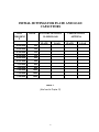

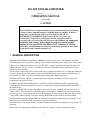
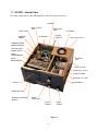

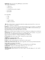
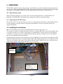
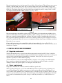
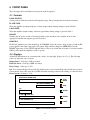
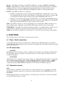
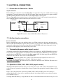
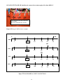
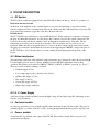
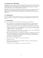
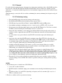
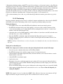
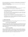
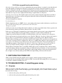
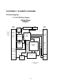

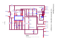

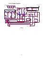
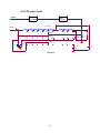

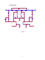

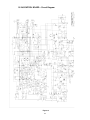
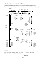
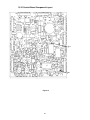
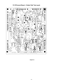
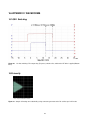
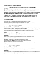

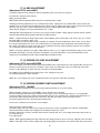
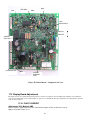

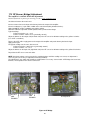

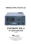
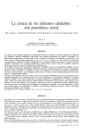
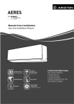
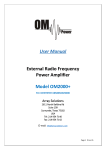
![(資料2) [PDFファイル/631KB]](http://vs1.manualzilla.com/store/data/006699017_2-da6e7ab4ce809f77027a2705646a6a6f-150x150.png)