1
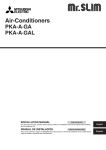
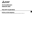
Air-Conditioners For Building Application
INDOOR UNIT
PCFY-P·NGMU-E
INSTALLATION MANUAL
For safe and correct use, please read this installation manual thoroughly before installing the air-conditioner unit.
Contents
1.
2.
3.
4.
Safety precautions ...................................................................................
Installation location ..................................................................................
Installing the indoor unit ...........................................................................
Installing the refrigerant piping .................................................................
2
3
3
5
5. Drainage piping work ............................................................................... 6
6. Electrical work .......................................................................................... 7
7. Test run .................................................................................................... 9
1. Safety precautions
s Before installing the unit, make sure you read all the “Safety precautions”.
s Please report to your supply authority or obtain their consent before
connecting this equipment to the power supply system.
Warning:
Describes precautions that must be observed to prevent danger of injury or
death to the user.
Caution:
Describes precautions that must be observed to prevent damage to the unit.
Warning:
• Ask a dealer or an authorized technician to install the unit.
• For installation work, follow the instructions in the Installation Manual and
use tools and pipe components specifically made for use with refrigerant
specified in the outdoor unit installation manual.
• The unit must be installed according to the instructions in order to minimize
the risk of damage from earthquakes, typhoons, or strong winds. An incorrectly installed unit may fall down and cause damage or injuries.
• The unit must be securely installed on a structure that can sustain its weight.
• If the air conditioner is installed in a small room, measures must be taken to
prevent the refrigerant concentration in the room from exceeding the safety
limit in the event of refrigerant leakage. Should the refrigerant leak and cause
the concentration limit to be exceeded, hazards due to lack of oxygen in the
room may result.
After installation work has been completed, explain the “Safety Precautions,” use,
and maintenance of the unit to the customer according to the information in the Operation Manual and perform the test run to ensure normal operation. Both the Installation Manual and Operation Manual must be given to the user for keeping. These
manuals must be passed on to subsequent users.
: Indicates a part which must be grounded.
Warning:
Carefully read the labels affixed to the main unit.
• Ventilate the room if refrigerant leaks during operation. If refrigerant comes
into contact with a flame, poisonous gases will be released.
• All electric work must be performed by a qualified technician according to
local regulations and the instructions given in this manual.
• Use only specified cables for wiring.
• The terminal block cover panel of the unit must be firmly attached.
• Use only accessories authorized by Mitsubishi Electric and ask a dealer or
an authorized technician to install them.
• The user should never attempt to repair the unit or transfer it to another location.
• After installation has been completed, check for refrigerant leaks. If refrigerant leaks into the room and comes into contact with the flame of a heater or
portable cooking range, poisonous gases will be released.
1.1. Before installation (Environment)
Caution:
• Do not use the unit in an unusual environment. If the air conditioner is installed in areas exposed to steam, volatile oil (including machine oil), or
sulfuric gas, areas exposed to high salt content such as the seaside, the
performance can be significantly reduced and the internal parts can be damaged.
• Do not install the unit where combustible gases may leak, be produced, flow,
or accumulate. If combustible gas accumulates around the unit, fire or explosion may result.
• Do not keep food, plants, caged pets, artwork, or precision instruments in
the direct airflow of the indoor unit or too close to the unit, as these items can
be damaged by temperature changes or dripping water.
• When the room humidity exceeds 80% or when the drainpipe is clogged, water may drip from the indoor unit. Do not install the indoor unit where such
dripping can cause damage.
• When installing the unit in a hospital or communications office, be prepared
for noise and electronic interference. Inverters, home appliances, high-frequency medical equipment, and radio communications equipment can cause
the air conditioner to malfunction or breakdown. The air conditioner may
also affect medical equipment, disturbing medical care, and communications
equipment, harming the screen display quality.
1.2. Before installation or relocation
Caution:
• Be extremely careful when transporting the units. Two or more persons are
needed to handle the unit, as it weighs 44 lbs. (20 kg) or more. Do not grasp
the packaging bands. Wear protective gloves as you can injure your hands
on the fins or other parts.
• Be sure to safely dispose of the packaging materials. Packaging materials,
such as nails and other metal or wooden parts may cause stabs or other
injuries.
• Thermal insulation of the refrigerant pipe is necessary to prevent condensation. If the refrigerant pipe is not properly insulated, condensation will be formed.
• Place thermal insulation on the pipes to prevent condensation. If the drainpipe is installed incorrectly, water leakage and damage to the ceiling, floor,
furniture, or other possessions may result.
• Do not clean the air conditioner unit with water. Electric shock may result.
• Tighten all flare nuts to specification using a torque wrench. If tightened too
much, the flare nut can break after an extended period.
1.3. Before electric work
Caution:
• Be sure to install circuit breakers. If not installed, electric shock may result.
• For the power lines, use standard cables of sufficient capacity. Otherwise, a
short circuit, overheating, or fire may result.
• When installing the power lines, do not apply tension to the cables.
• Be sure to ground the unit. If the unit is not properly grounded, electric shock
may result.
• Use circuit breakers (ground fault interrupter, isolating switch (+B fuse), and
molded case circuit breaker) with the specified capacity. If the circuit breaker
capacity is larger than the specified capacity, breakdown or fire may result.
1.4. Before starting the test run
Caution:
• Turn on the main power switch more than 12 hours before starting operation.
Starting operation just after turning on the power switch can severely damage the internal parts.
• Before starting operation, check that all panels, guards and other protective
parts are correctly installed. Rotating, hot, or high voltage parts can cause
injuries.
2
• Do not operate the air conditioner without the air filter set in place. If the air
filter is not installed, dust may accumulate and breakdown may result.
• Do not touch any switch with wet hands. Electric shock may result.
• Do not touch the refrigerant pipes with bare hands during operation.
• After stopping operation, be sure to wait at least five minutes before turning
off the main power switch. Otherwise, water leakage or breakdown may result.
2. Installation location
B
2.1. Outline dimensions (Indoor unit) (Fig. 2-1)
W
Select a proper position allowing the following clearances for installation and maintenance.
A
(inch)
Models
P15
P24
P30
P36
H
D
W
39-5/8
51-9/16
51-9/16
63-3/4
D
26-7/32
26-7/32
26-7/32
26-7/32
H
8-9/32
8-9/32
10-5/8
10-5/8
A
Min.10-5/8
Min.10-5/8
Min.10-5/8
Min.10-5/8
B
C
E
Min.11-13/16 Min.19-11/16 Max. 9-13/16
Min.11-13/16 Min.19-11/16 Max. 9-13/16
Min.11-13/16 Min.19-11/16 Max. 9-13/16
Min.11-13/16 Min.19-11/16 Max. 9-13/16
Warning:
Mount the indoor unit on a ceiling strong enough to withstand the weight of the
unit.
C
E
2.2. Outline dimensions (Outdoor unit)
Fig. 2-1
Refer to the outdoor unit installation manual.
3. Installing the indoor unit
1
3.1. Check the indoor unit accessories (Fig. 3-1)
3
2
The indoor unit should be supplied with the following accessories (contained in the
inside of the intake grille).
5
7
8
1
2
3
4
5
6
7
8
6
UNIT
4
Accessory name
Washer
Pipe cover
Pipe cover
Band
Joint socket
Socket cover
Drain tubing cover
Flare nut P36
Q’ty
4 pcs
1 pc
Large size (For gas tubing)
1 pc
Small size (For liquid tubing)
4 pcs
1 pc
Marked with “UNIT”
1 pc
1 pc
1 <3/4" (ø19.05)>
3-19/128
Fig. 3-1
B
A
(inch)
C
3.2. Preparation for installation (Fig. 3-2)
Must be installed at least 8 ft. (2.4 m) above floor or grade level.
Models
P15
P24
P30
P36
7/16
C
8-9/32
8-9/32
10-5/8
10-5/8
D
(inch)
E
2-61/64
G
D
5-7/16
H
Models
P15
P24
P30
P36
A
B
C
D
E
GH
D
5-5/32
5-5/32
7-9/16
7-1/2
E
6-7/8
6-7/8
9-9/32
9-9/32
Front side outlet
Left side outlet
Right side outlet
Independent piece (Removable)
F
7-1/16
7-1/16
7-2/32
7-2/32
E
F
G
H
Right drain tubing
Left drain tubing
Gas tubing
Liquid tubing
C
B
8-7/8
B
39-5/8
51-9/16
51-9/16
63-3/4
3.2.2. Refrigerant and drain tubing location
1-13/16
F
A
36-23/32
48-13/16
48-13/16
60-29/32
3-5/8 3-3/8
A
F
1-11/16
(inch)
26-3/4
12-19/32
3.2.1. Suspension bolt installing spacing
F
E
7-3/16
H
7-13/16
G
9-5/8
Fig. 3-2
B
(inch)
3.2.3. Selection of suspension bolts and tubing positions (Fig. 3-3)
Using the pattern paper provided for installation, select proper positions for suspension bolts and tubing and prepare relative holes.
6-11/16(9-7/128)
3-19/128
2-3/4
5-121/128(8-5/16)
A
Ø2-1/2
C
Ø3-15/16
4-59/64
A Pattern paper
B Suspension bolt hole
C Indoor unit width
Secure the suspension bolts or use angle stock braces or square timbers for bolt
installation.
A Use inserts of 220-230 lbs. each.
B Use suspension bolts of W3/8 or M10 in size
A
B
Fig. 3-3
3
3. Installing the indoor unit
■ PCFY-P15, P24NGMU-E
3.2.4. Fresh air intake hole (Fig. 3-4)
C B
A
At the time of installation, use the duct holes (knock out) located at the positions
shown in following diagram, as and when reguired.
A
D
C
E
B
A Indoor unit
B Fresh air intake hole (knock out hole)
C 4-ø1/8" (ø2.8) burring hole (P15, P24)
8-ø1/8" (ø2.8) burring hole (P30, P36)
inch (mm)
F
G
Models
■ PCFY-P30, P36NGMU-E
A
P15
C B
P24
A
B
3-3/16
(80.9)
3-11/32
(84.7)
5-7/32
(132.3)
C
2-7/16
(62)
2-1/8
(54)
5-29/32
(150)
D
1-25/32
(45)
1-5/8
(41)
3-21/32
(93)
E
1-21/32
(42)
1-1/2
(38)
3-21/32
(93)
F
1-3/4
(44.6)
3-31/32
(100.5)
7-7/8
(200)
G
2-29/32
(73.6)
5-9/32
(134.5)
9-9/32
(236)
H
–
–
3-15/16
(100)
D E
C
B
P30,P36
A
12-23/32
(323.1)
13-29/32
(353.6)
16-15/16
(430)
H
F
G
Fig. 3-4
3.2.5. Indoor unit preparation (Fig. 3-5)
1. Install the suspending bolts. (Procure the W3/8 or M10 bolts locally.)
Predetermine the length from the ceiling (1 within 100 mm).
A
1
C
A Ceiling surface
B Suspending bolt
C Suspending bracket
B
25/64-25/32
Fig. 3-5
b
a
(inch)
2. Remove the intake grille.
Slide the intake grille holding knobs (at two locations) backward to open the intake
grille.
3. Remove the side panel.
Remove the side panel holding screws (one in each side, right and left) then slide the
side panel forward for removal.
3.3. Installing the indoor unit
Use a proper suspending method depending on the presence or absence of ceiling
materials as follows. (Fig. 3-6)
In the absence of ceiling materials
Fig. 3-6
a Suspending bracket
b Unit
1) Directly suspending the unit (Fig. 3-7)
Installing procedures
1. Install the washer 1 (supplied with the unit) and the nut (to be locally procured).
2. Set (hook) the unit through the suspending bolts.
3. Tighten the nuts.
Check the unit installing condition.
• Check that the unit is horizontal between the right and left sides.
• Check that the unit slopes continuously downward from the front to the rear.
Fig. 3-7
A
1/4-15/32
B
C
D
E
F
G
A
B
C
D
E
F
G
H
C
Fig. 3-8
4
When embedding pipes, into the wall
2) Installing the suspending bracket first onto the ceiling (Fig. 3-8)
Installing procedures
1. Remove the suspending brackets, U-shaped washers, and suspending bracket
holding screws from the unit.
2. Adjust the suspending bracket holding bolts on the unit.
3. Attach the suspending brackets to the suspending bolts.
4. Set (hook) the unit to the suspending brackets.
∗ Be sure to install the U-shaped washers.
Bolt
Unit
Washer
Suspending bracket holding screw
Bolt
Washer 1
Double nuts
(inch)
H P15
35-7/16 - 35-41/64
P24, P30 47-1/2 - 47-23/32
P36
59-39/54 - 59-13/16
4. Installing the refrigerant piping
4.1. Precautions
4.1.1. For devices that use R22 refrigerant
• Use the refrigeration oil applied to the flared sections.
• Use C1220 copper phosphorus, for copper and copper alloy seamless pipes,
to connect the refrigerant pipes. Use refrigerant pipes with the thicknesses
specified in the table to the below. Make sure the insides of the pipes are
clean and do not contain any harmful contaminants such as sulfuric compounds, oxidants, debris, or dust.
4.1.2. For devices that use R410A refrigerant
• Use ester oil, ether oil, alkylbenzene oil (small amount) as the refrigeration
oil applied to the flared sections.
• Use C1220 copper phosphorus, for copper and copper alloy seamless pipes,
to connect the refrigerant pipes. Use refrigerant pipes with the thicknesses
specified in the table to the below. Make sure the insides of the pipes are
clean and do not contain any harmful contaminants such as sulfuric compounds, oxidants, debris, or dust.
Warning:
When installing or moving the air conditioner, use only the specified refrigerant (R410A) to charge the refrigerant lines. Do not mix it with any other refrigerant and do not allow air to remain in the lines. Air enclosed in the lines can
cause pressure peaks resulting in a rupture and other hazards.
Liquid pipe
Gas pipe
in. (mm)
P15
P24, P30, P36
1/4" (ø6.35) thickness 1/32" (0.8) 3/8" (ø9.52) thickness 1/32" (0.8)
1/2" (ø12.7) thickness 1/32" (0.8) 5/8" (ø15.88) thickness 3/64" (1.0)
• Do not use pipes thinner than those specified above.
A
B
45°±2°
4.2. Connecting pipes (Fig. 4-1)
øA
/6
R1
90° ±0.5°
C
2
1/3
oR
4t
D
Fig. 4-1
• When commercially available copper pipes are used, wrap liquid and gas pipes
with commercially available insulation materials (heat-resistant to 212 °F (100 °C)
or more, thickness of 1/2 in. (12 mm) or more).
• The indoor parts of the drain pipe should be wrapped with polyethylene foam insulation materials (specific gravity of 0.03, thickness of 23/64 in. (9 mm) or more).
• Apply thin layer of refrigerant oil to pipe and joint seating surface before tightening
flare nut.
• Use two wrenches to tighten piping connections.
• Use refrigerant piping insulation provided to insulate indoor unit connections. Insulate carefully.
B Flare nut tightening torque
A Flare cutting dimensions
Copper pipe O.D.
1/4" (ø6.35)
3/8" (ø9.52)
1/2" (ø12.7)
5/8" (ø15.88)
3/4" (ø19.05)
Copper pipe O.D.
in. (mm)
1/4" (ø6.35)
1/4" (ø6.35)
3/8" (ø9.52)
1/2" (ø12.7)
1/2" (ø12.7)
5/8" (ø15.88)
5/8" (ø15.88)
3/4" (ø19.05)
in. (mm)
Flare dimensions
øA dimensions
11/32-23/64 (8.7 - 9.1)
1/2-33/64 (12.8 - 13.2)
41/64-21/32 (16.2 - 16.6)
49/64-25/32 (19.3 - 19.7)
15/16-61/64 (23.6 - 24.0)
A
Flare nut O.D.
in. (mm)
43/64 (17)
7/8 (22)
7/8 (22)
1-3/64 (26)
1-9/64 (29)
1-9/64 (29)
1-27/64 (36)
1-27/64 (36)
Tightening torque
ft·lbs. (N·m)
10-13 (14 - 18)
25-30 (34 - 42)
25-30 (34 - 42)
35-44 (49 - 61)
49-59 (68 - 82)
49-59 (68 - 82)
72-87 (100 - 120)
72-87 (100 - 120)
C Apply refrigerating machine oil over the entire flare seat surface.
D Use correct flare nuts meeting the pipe size of the outdoor unit.
A Die
B Copper pipe
Available pipe size
A
B
Fig. 4-2
in. (mm)
in. (mm)
P15
P24, P30
P36
1/4" (ø6.35)
–
–
Liquid side
–
3/8" (ø9.52)
3/8" (ø9.52)
1/2" (ø12.7)
–
–
Gas side
–
5/8" (ø15.88)
5/8" (ø15.88)
–
–
3/4" (ø19.05)
: Factory flare nut attachment to the heat-exchanger.
A
Copper pipe O.D.
1/4" (ø6.35)
3/8" (ø9.52)
1/2" (ø12.7)
5/8" (ø15.88)
3/4" (ø19.05)
Flare tool for R22
Flare tool for R410A
Clutch type
0-1/64 (0 - 0.5)
3/64-1/16 (1.0 - 1.5)
0-1/64 (0 - 0.5)
3/64-1/16 (1.0 - 1.5)
0-1/64 (0 - 0.5)
3/64-1/16 (1.0 - 1.5)
0-1/64 (0 - 0.5)
3/64-1/16 (1.0 - 1.5)
0-1/64 (0 - 0.5)
3/64-1/16 (1.0 - 1.5)
5
4. Installing the refrigerant piping
4.3. Indoor unit (Fig. 4-3)
A
B
C
C
D
A
B
C
D
Gas tubing
Liquid tubing
Band 4
Pipe cover 2
E Pipe cover 3
F Press the pipe cover against the sheet metal.
G Refrigerant tubing heat insulating material
4.4. For twin/triple combination
E
DE
Installing procedures
1. Slide the supplied pipe cover 2 over the gas tubing until it is pressed against the
sheet metal inside the unit.
2. Slide the provided pipe cover 3 over the liquid tubing until it is pressed against
the sheet metal inside the unit.
3. Tighten the pipe covers 2 and 3 at the both ends 5/8 - 3/4 in. (15 - 20 mm) with
the supplied bands 4.
Refer to the outdoor unit installation manual.
G
F
Fig. 4-3
5. Drainage piping work
A
5.1. Preparation for left side tubing installation (Fig. 5-1)
A Drain pan
B Plug
• For left side tubing, be sure to insert the rubber plug into the right drain port.
• Install the drain tubing as it slopes continuously downward.
• After completion of work, check that correct drain is available from the outflow port
of the drain tubing.
B
Fig. 5-1
A
C
D
B
3.B
1.D
E
A
B
C
D
E
2.C
Drain pan
Drain tubing (VP20)
Socket cover 6
Joint socket 5
Drain tubing cover 7
Fig. 5-2
4.E
F
F Drain tubing sensor
Fig. 5-3
6
Installing procedures (Fig. 5-2)
1. Attach the joint socket 5 supplied with the unit to the drain port on the unit with a
vinyl chloride adhesive.
2. Fasten the socket cover 6 supplied with the unit to the joint socket 5.
3. Attach the field drain tubing (VP20/O.D. ø26 PVC TUBE) to the joint socket 5
with a vinyl chloride adhesive.
4. Wrap the drain tubing cover 7 supplied with the unit. (Seam taping)
5. Check for correct drainage. (Fig. 5-3)
∗ Fill the drain pan with water of about 1 L from the tubing sensor access port.
∗ After checking for correct drainage, replace the tubing sensor access port cover.
6. Electrical work
6.1. Electric wiring (Fig. 6-1)
C
A
D
B
E
Wiring procedures
1. Remove the (two) tapping screws then remove the electric part cover.
2. Connect the electric wires securely to the corresponding terminals.
3. Replace the removed parts.
4. Tie the electric wires with the local wiring clamp located in the right side of the
junction box.
F
G
L1 L2 GR
H
L1
M1 M2 S
L2 GR
A
B
C
D
E
F
G
H
I
J
K
1
M1 M2 S
I
1
2
J
Cover
Set screws
Beam
Wiring clamp
Power supply board
Control board
Wire service entrance
Terminal block for power supply
Terminal block for transmission cable
Terminal block for remote controller
Grounding cable connector
K
2
Fig. 6-1
A
B
D
C
C
C
6.2. Power supply wiring (Fig. 6-2)
C
C
C
C
E
A
B
C
D
E
Switch 15 A
Overcurrent protection 15 A
Indoor unit
Total operating current be less than 15 A
Ground
Fig. 6-2
Power cable size (diameter) : more than 1.6 mm (AWG14)
Ground cable size (diameter) : 1.6 mm (AWG14)
* Use copper supply wires.
* Use the electric wires over the rating voltage 300 V.
[Selecting non-fuse breaker (NF) or earth leakage breaker (NV)]
To select NF or NV instead of a combination of Class B fuse with switch, use the
following:
• In the case of Class B fuse rated 15 A or 20 A,
NF model name (MITSUBISHI): NF30-CS (15 A) (20 A)
NV model name (MITSUBISHI): NV30-CA (15 A) (20 A)
Use an earth leakage breaker with a sensitivity of less than 30 mA 0.1 sec.
Caution:
Do not use anything other than the correct capacity breaker and fuse. Using
fuse, wire or copper wire with too large capacity may cause a risk of malfunction or fire.
1
B
A
M1 M2
A
M1 M2 S
TB3
TB5
1 2
M1 M2 S
TB15 TB5
D
TB15
E
C
C
Fig. 6-3
B
2
1 2
M1 M2
TB3
A
A
M1 M2 S
M1 M2 S
TB5
D
TB5
6.3. Connecting remote controller, indoor and outdoor
transmission cables
• Connect indoor unit TB5 and outdoor unit TB3. (Non-polarized 2-wire)
The “S” on indoor unit TB5 is a shielding wire connection. For specifications about
the connecting cables, refer to the outdoor unit installation manual.
• Install a remote controller following the manual supplied with the remote controller.
• Connect the remote controller’s transmission cable within 33 ft (10 m) using a
0.75 mm2 (AWG18) core cable. If the distance is more than 33 ft (10 m), use a 1.25
mm2 junction cable.
1 MA Remote controller (Fig. 6-3)
• Connect the “1” and “2” on indoor unit TB15 to a MA remote controller. (Non-polarized 2-wire)
• DC 9 to 13 V between 1 and 2 (MA remote controller)
2 M-NET Remote controller (Fig. 6-4)
• Connect the “M1” and “M2” on indoor unit TB5 to a M-NET remote controller. (Nonpolarized 2-wire)
• DC 24 to 30 V between M1 and M2 (M-NET remote controller)
A Terminal block for indoor transmission cable
B Terminal block for outdoor transmission cable
C Remote controller
D Transmission cables
E Remote control cables
E
C
C
Fig. 6-4
7
6. Electrical work
Constraints on transmission cable
G
*1
Longest wiring length (L1+L2+L4 or L1+L3 or L2+L3+L4): less than 656 ft (200 m)
Length between indoor unit and remote controller (R): within 33 ft (10 m)
H
I
G
H
I
J
K
L
*3
J
J
J
L1
L2
K
J
L
K
K
J
L3
L4
K
K
Fig. 6-5
r
Outdoor unit
Earth
BC controller
Indoor unit
M-NET Remote controller
Non-polarized 2-wire
*2
Note:
*1 Put the transmission cable earth via the outdoor unit’s earth terminal
to
the ground.
*2 If the remote controller cable exceeds 33 ft (10 m), use a 1.25 mm2 (AWG16)
diameter cable over the exceeded portion, and add that exceeded portion
to within 656 ft (200 m).
*3 The BC controller is required only for simultaneous cooling and heating
series R2.
Types of control cables (Fig. 6-5)
1. Wiring transmission cables: Shielding wire CVVS or CPEVS
• Cable diameter: More than 1.25 mm2 (AWG16)
2. M-NET Remote control cables
Kind of remote control cable
2-core cable (unshielded)
Cable diameter
More than 0.5 (AWG20) to 0.75 mm2 (AWG18)
Remarks
When 10 m is exceeded, use cable with the
same specifications as transmission line wiring
(shielding portion is more than 1.25 mm 2
(AWG16))
3. MA Remote control cables
Kind of remote control cable
Cable diameter
2-core cable (unshielded)
0.3 mm2 (AWG22) to 1.25 mm2 (AWG16)
6.4. Setting addresses (Fig. 6-6)
Address board
SW5
220V
(208V)
SWA
240V 3
(230V) 2
1
CN43
SW1
ON
OFF
CN82
1 2 3 4 5 6 7 8 9 10
SW12
SW11
0
0
Fig. 6-6
SWC
SW14
0
(Be sure to operate with the main power turned OFF.)
• There are two types of rotary switch setting available: setting addresses 1 to 9 and
over 10, and setting branch numbers.
1 How to set addresses
Example: If Address is “3”, remain SW12 (for over 10) at “0”, and match SW11(for
1 to 9) with “3”.
2 How to set branch numbers (Series R2 only)
Match the indoor unit’s refrigerant pipe with the-xC controller’s end connection
number. Remain SW14 other than R2 at “0”.
• The rotary switches are all set to “0” when shipped from the factory. These switches
can be used to set unit addresses and branch numbers at will.
• The determination of indoor unit addresses varies with the system at site. Set them
referring to technical data.
Note:
Please set the switch SW5 according to the power supply voltage.
• Set SW5 to 230 V side when the power supply is 230 volts.
• When the power supply is 208 volts, set SW5 to 208 V side.
6.5. Switch setting for different ceiling heights
With this unit, the air flow rate and fan speed can be adjusted by setting the SWA
(slide switch). Select a suitable setting from the table below according to the installation location.
* Make sure the SWA switch is set, otherwise problems such as no wind blowing will
occur.
Ceiling Height
11.5 ft. (3.5 m)
9.2 ft. (2.8 m)
7.5 ft. (2.3 m)
SWA
3 (high ceiling)
2 (standard)
1 (low ceiling)
SWA: Factory setting: 2 (Standard)
6.6. Sensing room temperature with the built-in sensor
in a remote controller
If you want to sense room temperature with the built-in sensor in a remote controller,
set SW1-1 on the control board to “ON”. The setting of SW1-7 and SW1-8 as necessary also makes it possible to adjust the air flow at a time when the heating thermometer is OFF.
8
6. Electrical work
B
inch (mm)
A
1-3/16
(30)
1) Installing procedures
(1) Select an installing position for the remote controller. (Fig. 6-7)
The temperature sensors are located on both remote controller and indoor unit.
s Procure the following parts locally:
Two piece switch box
Thin copper conduit tube
Lock nuts and bushings
1-3/16
(30)
1-37/64 (46)
C
A
C
D
E
F
4-23/32 (120)
3-9/32 (83.5)
1-3/16
(30)
I
G
H
Fig. 6-7
B-1.
B-2.
B
H
H
I
6.7. Remote controller
J
A Remote controller profile
B Required clearances surrounding the remote controller
C Installation pitch
(2) Seal the service entrance for the remote controller cord with putty to prevent possible invasion of dew drops, water, cockroaches or worms. (Fig. 6-8)
A For installation in the switch box:
B For direct installation on the wall select one of the following:
• Prepare a hole through the wall to pass the remote controller cord (in order to run
the remote controller cord from the back), then seal the hole with putty.
• Run the remote controller cord through the cut-out upper case, then seal the cutout notch with putty similarly as above.
B-1. To lead the remote controller cord from the back of the controller:
B-2. To run the remote controller cord through the upper portion:
(3) For direct installation on the wall
C
D
E
F
G
H
I
J
I
Fig. 6-8
Wall
Conduit
Lock nut
Bushing
Switch box
Remote controller cord
Seal with putty
Wood screw
2) Connecting procedures (Fig. 6-9)
1 Connect the remote controller cord to the terminal block.
A
A To TB5 on the indoor unit
B TB6 (No polarity)
AB
Fig. 6-9
TB6
B
3) Temperature display setting
The initial temperature display setting is °C. Please change the setting to °F. Refer to
“Function selection of remote controller (Section 8)” in the operation manual for the
indoor unit.
4) Two remote controllers setting
If two remote controllers are connected, set one to “Main” and the other to “Sub”. For
setting procedures, refer to “Function selection of remote controller” in the operation
manual for the indoor unit.
7. Test run
7.1. Before test run
s After completing installation and the wiring and piping of the indoor and
outdoor units, check for refrigerant leakage, looseness in the power supply
or control wiring, wrong polarity, and no disconnection of one phase in the
supply.
s Use a 500-volt megohmmeter to check that the resistance between the power
Ω.
supply terminals and ground is at least 1.0 MΩ
F E
C
D B
TEST RUN
COOL, HEAT
˚F
˚F
SIMPLE
TEMP.
MENU
BACK
MONITOR/SET
PAR-21MAA
HG
ON/OFF
ON/OFF
CLOCK
A
FILTER
DAY
CHECK TEST
OPERATION
CLEAR
I M
Fig. 7-1
A ON/OFF button
B Test run display
C Indoor temperature liquid line
temperature display
D ON/OFF lamp
E Power display
F Error code display
Test run remaining time display
G Set temperature button
H Mode selection button
I Fan speed button
M TEST button
s Do not carry out this test on the control wiring (low voltage circuit) terminals.
Warning:
Ω.
Do not use the air conditioner if the insulation resistance is less than 1.0 MΩ
Insulation resistance
7.2. Test run (Fig. 7-1)
The following 3 methods are available.
1 Turn on the power at least 12 hours before the test run.
2 Press the [TEST] button twice. ➡ “TEST RUN” liquid crystal display
3 Press the [Mode selection] button. ➡ Make sure that wind is blown out.
4 Press the [Mode selection] button and switch to the cooling (or heating) mode.
➡ Make sure that cold (or warm) wind is blown out.
5 Press the [Fan speed] button. ➡ Make sure that the wind speed is switched.
6 Check operation of the outdoor unit fan.
7 Release test run by pressing the [ON/OFF] button. ➡ Stop
8 Register a telephone number.
The telephone number of the repair shop, sales office, etc., to contact if an error
occurs can be registered in the remote controller. The telephone number will be
displayed when an error occurs. For registration procedures, refer to the operation manual for the indoor unit.
Note:
• If an error code is displayed on the remote controller or if the air conditioner
does not operate properly, refer to the outdoor unit installation manual or
other technical materials.
• The OFF timer is set for the test run to automatically stop after 2 hours.
• During the test run, the time remaining is shown in the time display.
• During the test run, the temperature of the indoor unit refrigerant pipes is
shown in the room temperature display of the remote controller.
• When the VANE or LOUVER button is pressed, the message “NOT AVAILABLE” may appear on the remote controller display depending on the indoor
unit model, but this is not a malfunction.
9
This product is designed and intended for use in the residential,
commercial and light-industrial environment.
Please be sure to put the contact address/telephone number on
this manual before handing it to the customer.
HEAD OFFICE: MITSUBISHI DENKI BLDG., 2-2-3, MARUNOUCHI, CHIYODA-KU, TOKYO 100-8310, JAPAN
BG79U668H01
Printed in Japan