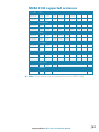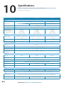
1
HDS Gen3 Installation Manual ENGLISH lowrance.com Preface As Navico is continuously improving this product, we retain the right to make changes to the product at any time which may not be reflected in this version of the manual. Please contact your nearest distributor if you require any further assistance. It is the owner’s sole responsibility to install and use the instrument and transducers in a manner that will not cause accidents, personal injury or property damage. The user of this product is solely responsible for observing safe boating practices. NAVICO HOLDING AS AND ITS SUBSIDIARIES, BRANCHES AND AFFILIATES DISCLAIM ALL LIABILITY FOR ANY USE OF THIS PRODUCT IN A WAY THAT MAY CAUSE ACCIDENTS, DAMAGE OR THAT MAY VIOLATE THE LAW. Governing Language: This statement, any instruction manuals, user guides and other information relating to the product (Documentation) may be translated to, or has been translated from, another language (Translation). In the event of any conflict between any Translation of the Documentation, the English language version of the Documentation will be the official version of the Documentation. This manual represents the product as at the time of printing. Navico Holding AS and its subsidiaries, branches and affiliates reserve the right to make changes to specifications without notice. Copyright Copyright © 2014 Navico Holding AS. Warranty The warranty card is supplied as a separate document. In case of any queries, refer to the brand web site of your display or system: www.lowrance.com Declarations and conformance This equipment is intended for use in international waters as well as inland waters and coastal sea areas administered by countries of the USA, E.U. and E.E.A. |1 Compliance Statements Lowrance HDS-7, HDS-9, and HDS-12 Gen3: • complies with CE under R&TTE directive 1999/5/ EC • complies with the requirements of level 2 devices of the Radio-communications (Electromagnetic Compatibility) standard 2008 • This device complies with Part 15 of the FCC Rules. Operation is subject to the following two conditions: (1) this device may not cause harmful interference, and (2) this device must accept any interference received, including interference that may cause undesired operation. The relevant Declaration of Conformity is available on the following website, under the model documentation section: www.lowrance.com Industry Canada IC RSS-GEN, Sec 7.1.3 Warning Statement- (Required for licenseexempt devices) This device complies with Industry Canada license-exempt RSS standard(s). Operation is subject to the following two conditions: (1) this device may not cause interference, and (2) this device must accept any interference, including interference that may cause undesired operation of the device. Le présent appareil est conforme aux CNR d’Industrie Canada applicables aux appareils radio exempts de licence. L’exploitation est autorisée aux deux conditions suivantes : (1) l’appareil ne doit pas produire de brouillage, et (2) l’utilisateur de l’appareil doit accepter tout brouillage radioélectrique subi, même si le brouillage est susceptible d’en compromettre le fonctionnement. Warning The user is cautioned that any changes or modifications not expressly approved by the party responsible for compliance could void the user’s authority to operate the equipment. This equipment has been tested and found to comply with the limits for a Class B digital device, pursuant to Part 15 of the FCC rules. These limits are designed to provide 2| • • • • reasonable protection against harmful interference in a residential installation. This equipment generates, uses and can radiate radio frequency energy and, if not installed and used in accordance with the instructions, may cause harmful interference to radio communications. However, there is no guarantee that the interference will not occur in a particular installation. If this equipment does cause harmful interference to radio or television reception, which can be determined by turning the equipment off and on, the user is encouraged to try to correct the interference by one or more of the following measures: Reorient or relocate the receiving antenna Increase the separation between the equipment and receiver Connect the equipment into an outlet on a circuit different from that of the receiver Consult the dealer or an experienced technician for help |3 Countries of intended use in the EU: AT - Austria BE - Belgium BG - Bulgaria CY - Cyprus CZ - Czech Republic DK - Denmark EE - Estonia FI - Finland FR - France DE - Germany GR - Greece HU - Hungary IS - Iceland IE - Ireland IT - Italy LI - Liechtenstein LV - Latvia LT - Lithuania LU - Luxembourg MT - Malta NL - Netherlands NO - Norway PL - Poland PT - Portugal RO - Romania SK - Slovakia SI - Slovenia ES - Spain SE - Sweden CH - Switzerland TR - Turkey UK - United Kingdom 4| About this manual This manual is a reference guide for installing the Lowrance HDS-7, HDS-9, and HDS-12 Gen3 displays. The manual does not cover basic background information about how equipment such as radars, sonar, and AIS work. Important text that requires special attention from the reader is emphasized as follows: Note: Used to draw the reader’s attention to a comment or some important information. ! Warning: Used when it is necessary to warn personnel that they should proceed carefully to prevent risk of injury and/or damage to equipment/personnel. Trademarks • • • • • • ‘NMEA 2000’ is a registered trademark of the National Marine Electronics Association ‘Navionics’ is a registered trademark of Navionics SpA C-MAP is a trademark of Jeppesen SIRIUS is a registered trademark of SIRIUS ‘HDS’, ‘StructureScan’, ‘Navico’, ‘Lowrance’, ‘SonicHub’, ‘SimNet’ and ‘Skimmer’ are trademarks of Navico, registered in the US and other countries. ‘InsightHD’, ‘Broadband Radar’ and ‘Broadband Sonar’ are trademarks of Navico. ‘Simrad’ is a trademark of Kongsberg Maritime AS Company registered in the US and other countries and is being used under license. |5 Contents 6| 8 HDS Gen3 overview 9 10 11 Front - controls Rear - connectors SD card slot 12 Check the contents 13 Display Installation 13 14 15 Mounting location Bracket mounting Flush mounting 16 Mounting the transducer 16 16 17 18 Research Select a transducer location Attaching the transducer Adjusting the transducer 19 Wiring 19 20 22 23 24 26 27 Guidelines Power connection Transducer connection Ethernet device connection NMEA 2000 device connection NMEA 0183 device connection Video In 28 Software setup 28 30 31 32 34 34 35 36 37 First time startup Time and Date Source selection Device list Diagnostics Damping Sonar setup StructureScan and SpotlightScan Radar setup 38 39 41 43 44 46 49 49 49 Autopilot setup Fuel setup CZone setup NMEA 0183 setup Ethernet setup Wifi setup Video In configuration Mercury® Software updates and data backup 53 Dimensional drawings 53 53 53 HDS 7 Gen3 HDS 9 Gen3 HDS 12 Gen3 54 Accessories 54 54 54 55 55 NMEA 2000 Ethernet cables Display accessories Sonar accessories Other accessories 56 Supported data 56 61 NMEA 2000 compliant PGN List NMEA 0183 supported sentences 62 Specifications |7 1 8| HDS Gen3 overview All HDS-7, HDS-9, and HDS-12 Gen3 multifunction displays have built-in CHIRP/Broadband sonar, and StructureScan, capable of operating simultaneously. The ability to network over NMEA 2000 and Ethernet allows access to data as well as control of numerous optional devices that can provide sonar, radar, audio entertainment, weather and even digital switching. All displays are charting ready, with built-in high speed GPS receiver (10Hz) and support for Insight, Navionics®, and C-MAP™ cartography. The displays may be mounted to the vessel with the supplied surface mount bracket, or flush mounted in the dash. The displays are intended for 12 V DC operation, though will accept the moderate fluctuations commonly seen in DC systems. HDS Gen3 overview | HDS Gen3 Installation Manual Front - controls 2 1 3 5 7 9 6 10 4 8 11 1 Multi-touch touchscreen 2 Pages 3 Cursor (8-way) 4 Zoom out / Zoom in (combined press = MOB) 5 Exit (X) 6 Enter 7 Menu (short press = menu, long press = hide menu bar, double press = Settings menu) 8 Active panel 9 New waypoint (long press = find dialogue) 10 Power key (short press = system controls, long press = power off ) 11 Card reader door HDS Gen3 overview | HDS Gen3 Installation Manual |9 Rear - connectors HDS-9 / 12 1 2 2 3 4 HDS-7 5 2 1 4 5 3 1 NMEA 2000 - data input / output 2 ETHERNET - high bandwidth data (radar, sonar, chart) 3 POWER - 12V input & NMEA 0183. Optional video-in via adaptor 4 SONAR - CHIRP and Broadband Sonar 5 STRUCTURE - StructureScan HD sonar 10 | HDS Gen3 overview | HDS Gen3 Installation Manual MicroSD card slot Used for detailed chart data, software updates, transfer of user data and system backup. All size displays have two card reader slots. The card reader door is opened by sliding the door to the right (1) using your fingernail, then hinging forward (2) from the right hand side. 2 1 The card reader door should always be shut immediately after inserting or removing a card, in order to prevent possible water ingress. HDS Gen3 overview | HDS Gen3 Installation Manual | 11 2 Check the contents 2 6 11 7 1 8 4 3 12 9 5 10 13 1 HDS Gen3 display 2 Suncover 3 Bracket 4 Knobs 5 Fasteners (4 x 6G x 1.5 panhead PH1) 6 Power cable 7 Fuse holder (ATC blade) 8 Fuse (3 amp) 9 Caps (3x for HDS7 4x for HDS9/12 - for ethernet, NMEA 2000, StructureScan) 10 Documentation pack (Operator & Installation manual, Quick guide, warranty card) 11 83/200 kHz transducer (model dependant) 12 StructureScan HD transducer (model dependant) 13 50/200 kHz transducer (model dependant) 12 | Check the contents | HDS Gen3 Installation Manual 3 Display Installation Mounting location Choose the mounting locations carefully before you drill or cut. The display should be mounted so that the operator can easily use the controls and clearly see the display screen. Be sure to leave a direct path for all of the cables. Lowrance displays are high-contrast, and are viewable in direct sunlight, but for best results install the display out of direct sunlight. The chosen location should have minimal glare from windows or bright objects. Ensure that any holes cut are in a safe position and will not weaken the boat’s structure. If in doubt, consult a qualified boat builder, or marine electronics installer. Before cutting a hole in a panel, make sure that there are no hidden electrical wires or other parts behind the panel. Do not mount any part where it can be used as a hand hold, where it might be submerged, or where it will interfere with the operation, launching or retrieving of the boat. If bracket mounting the display, choose an area where the display will not be subjected to excessive vibration. The mounting location may affect the internal GPS receiver. Test the unit in it’s intended location to ensure satisfactory reception. An external GPS source may be added to overcome poor reception areas. Leave sufficient clearance to connect all relevant cables. Good ventilation is required. Inadequate ventilation may cause the display to overheat. Lowrance displays are designed to operate in temperatures from -15° C to +55° C (+5° F to +131° F). For overall width and height requirements, please see the dimensions section on page 53. ! Warning: When installing the displays, ensure appropriate safety equipment is used, eg. ear muffs, protective glasses, gloves and a dust mask. Power tools may exceed safe noise levels, and can cast off dangerous projectiles. The dust from many materials commonly used in boat construction may cause irritation or damage to eyes, skin, and lungs. Display Installation | HDS Gen3 Installation Manual | 13 Bracket mounting Place the bracket in the desired mounting location, and use a pencil or permanent marker to mark drilling locations. Note: ensure that the chosen location has enough height to accomodate the display fitted in the bracket, and allows tilting of the display. Also adequate space is required on both sides to allow tightening and loosening of the knobs. Use fasteners suited to the mounting surface material. If the material is too thin for self tappers, reinforce it, or mount the bracket with machine screws and large washers. Use only 304 or 316 stainless steel fasteners. Mark the screw locations using the bracket as a template, and drill pilot holes. Screw down the bracket. Mount the display to the bracket using the knobs. Hand tighten only. The ratchet teeth in the bracket and display case ensure a positive grip and prevent the unit changing from the desired angle. 14 | Display Installation | HDS Gen3 Installation Manual Flush mounting Check the template for scaling accuracy, using a tape measure or ruler against the ruler printed on the template. Cut away excess paper, and tape down the template. Check that it is correctly aligned to a vertical or horizontal reference. Do not use a bubble level as vessel may be unlevel! Adjust where required. Drill all marked pilot holes, then using an appropriate saw, cut through the template and mounting surface, along the dotted line bordering the shaded center of the template. Remove the bezel from the display by first opening the card reader door. Using a fingernail or small flat screwdriver, pull off the bezel at the slotted points immediately above and below the card reader. Pull bezel around keypad forward, till hidden tab at top right can be disengaged by a slight downward pull. Applying a slight twist to top bezel edge will disengage the top left hidden tab. The rest of the bezel should come away easily. 95 .3 m m (7 .5 0" ) MO UN TIN G SC RE W 110.2 mm (3.75") SIZ E IS #6 99.5 mm (3.92") 95 TA PP ING SC .3 C L RE W m m (7 .5 0" ) SU N PR OD UC CO VE R OU TL IN E C L T 19 0. 5 m m (7 .5 0" ) 199.0 mm (7.83") 220.4 mm (8.68") Check dimensions before cutting 12" Check the fit of the display, and use a file to remove any remaining obstructions. If water-tightness is required, apply a thin, continuous bead of sealant to the back of the display prior to final installation. Sealant should be of a ‘neutral cure’ type to prevent damage to the plastics. Secure the display with the supplied screws. Once screws are fully tightened, ensure there is complete contact with the mounting surface. Lastly, install the bezel with the card reader door open; insert the outermost tabs on the bezel into the slots on the display, then gently press down the bezel above and below the card reader door until it clicks in to place. Display Installation | HDS Gen3 Installation Manual | 15 Mounting the transducer 4 Transducer location selection and installation are two of the most critical steps in sonar installation. To function properly the transducer must be in the water at all times, and in a location that has a smooth flow of water while the boat is moving. Research • • • Before starting the installation of the transducer, it’s advised to check the following: Find out if the boat builder has a recommended installation location Establish direction of rotation of the propeller(s) Watch actual water flow when boat is travelling at cruising speed to determine the area of transom with the cleanest flow (least bubbles) Select a transducer location The primary aim is to stay clear of propeller and hull generated turbulence, while mounting the transducer as close to the center of the vessel as possible. 1 2 3 4 5 1 Avoid mounting within 1 m (3.3’) to port (left) of propeller 2 Conventional clockwise propeller rotation 3 Avoid mounting within 7.5 cm (3“) to starboard of propeller 4 Best mounting location - undisturbed water flow 5 Planing strake - avoid mounting behind here Note: Reverse the distance guides (1 & 3) from propeller where engine is of counterclockwise configuration. 16 | Mounting the transducer | HDS Gen3 Installation Manual Note: Boats with strakes or ribs on the hull can create large amounts of turbulence at higher speeds. A good transducer location on these types of boats is between the ribs closest to the engine. Note: If the transducer is not placed in a smooth flow of water, interference caused by bubbles and turbulence may show onscreen in the form of random lines or dots. The unit could also lose bottom signal when the boat is on plane. Note: Trim tabs will vary in the amount of turbulence they create as they are adjusted, stay clear of these. Attaching the transducer The transducer should be installed parallel with the transom’s waterline, not the bottom of the boat (deadrise). Note: Ensure the entire bottom surface of the transducer hangs at least 3 mm (1/8th of an inch) lower than the bottom of the hull. Hold the transducer with bracket up to the transom of the boat and trace the slotted screw hole locations (two on the 83/200 KHz transducer, and four on the 50/200 KHz transducer). Mark drilling points in the middle of each outline, to allow for transducer height adjustment. Drill pilot holes to suit fasteners. Note: Check that there is nothing on the other side of the mounting surface that may be damaged by drilling. Attach transducer to transom, using supplied stainless steel fasteners. Drill a 25 mm (1”) hole above the waterline, large enough to pass the plug through. Mounting the transducer | HDS Gen3 Installation Manual | 17 Secure the cable to the hull at regular intervals using cable P clips or saddles and ensure that moving parts such as an outboard motor or boarding ladder can’t snag the cable. Adjusting the transducer If the sonar image shows interference lines on the screen when moving, which worsen with speed, it may be possible to eliminate these by adjusting the transducer’s angle. Note: A transducer that is tilted too far in either direction will not perform well; missing targets, and/or losing the bottom at speed. If performance does not improve with tilting, try adjusting the height of the transducer relative to the transom of the boat. If the transducer is too high it may be seeing cavitation caused by the trailing edge of the transom. 18 | Mounting the transducer | HDS Gen3 Installation Manual 5 Wiring Guidelines Don’t do this Don’t make sharp bends in the cables Don’t run cables in a way that allows water to flow down into the connectors Don’t route the data cables in areas adjacent to radar, transmitter, or large current carrying cables Do this Do make drip and service loops Do cable tie all cables to keep them secure Do solder/crimp and insulate all wiring connections, if extending or shortening power or NMEA 0183 cables Do leave room at the back to install and remove cables ! Warning: Before starting the installation, be sure to turn electrical power off. If power is left on or turned on during the installation, fire, electrical shock, or other serious injury may occur. Be sure that the voltage of the power supply is compatible with the HDS Gen3 display ! Warning: The HDS Gen3 has a voltage rating of 12 V DC, it is not suited for use with 24V DC systems. ! Warning: The positive supply wire (red) should always be connected to (+) DC with the supplied fuse or a circuit breaker (closest available to fuse rating). Wiring | HDS Gen3 Installation Manual | 19 Power connection • • The plug of the supplied power cable has two discrete cables exiting from it. The thickest of the two cables provides the following: power into the system (Red and Black wires) remote turn-on for certain Navico expansion modules (Yellow wire) 3 1 2 4 5 _ + 6 1 HDS display rear (HDS9/12 connector arrangement shown) 2 Power cable 3 12 V positive wire (red) shown with fuse holder installed inline 4 12 V negative wire (black) 5 Accessory Wake Up wire (yellow) 6 Vessel’s 12 V DC supply Accessory wake up The yellow colored accessory wake up line may be used to control the power state of Navico modules such as SonicHub, StructureScan, and Broadband radar. This means that the modules are turned on the moment the display is powered up. For connection, simply combine all yellow wires on a common bus or to a single termination point. Note: Broadband radar will be started in ‘standby’ mode, never ‘transmit’ mode, when triggered by the accessory wake up line. The following demonstrates the power connections for a typical small system. 20 | Wiring | HDS Gen3 Installation Manual 1 2 3 4 5 6 7 + _ 8 1 HDS Displays (HDS7 connector arrangement shown) 2 HDS power cable 3 Broadband radar interface 4 SonicHub 5 12 V DC negative (-) 6 12 V DC postive (+) 7 Accessory wake up line 8 Vessel’s 12 V DC supply Wiring | HDS Gen3 Installation Manual | 21 Transducer connection All HDS Gen3 displays have internal CHIRP, Broadband and StructureScan sonar. Navico transducers fitted with the 7 pin blue connector can be plugged directly into the corresponding blue socket labeled ‘Sonar’. The 9 pin black StructureScan connector can be plugged in to the socket labelled ‘Structure’. Refer to the Overview section of this manual, or embossed labeling on the unit for connector location. Note: The connector attached to the transducer cable is keyed, and can only be inserted in one orientation. Once inserted, turn locking collar to secure. Note: The HDS StructureScan port is designed for use with the LSS-2 transducer. Earlier LSS-1 transducers may however be connected through use of an adaptor cable - contact your Lowrance dealer for more information. SpotlightScan The SpotlightScan transducer uses both the ‘Sonar’ and ‘Structure’ sockets. Refer to the SpotlightScan manual for further information. 22 | Wiring | HDS Gen3 Installation Manual Ethernet device connection Ethernet is used to connect high bandwidth devices such as radar, sonar, and other displays. The HDS-7 display has one ethernet port, whereas the HDS-9 and 12 displays have two. Navico ethernet cables have a locking collar, for maintaining a reliable, waterproof connection. Connecting directly to a single device The ethernet port is auto sensing, meaning that the unit can connect to one network device directly, without the use of a crossover cable or switch. Connecting to multiple devices If connecting more than one ethernet device to a HDS-7 display, or two devices to a HDS-9 or HDS-12 display, use the optional network expansion Port (NEP-2). If the number of ethernet devices exceeds the number of available ports on the NEP-2, it is possible to link two or more NEP-2 modules together to provide the required ports. The NEP-2 modules are fitted with 5 ethernet ports. Note: When designing a system, take in to account the ports ‘lost’ when used for linking multiple NEP-2 modules together. Wiring | HDS Gen3 Installation Manual | 23 NMEA 2000 device connection All HDS Gen3 models are equiped with a NMEA 2000 connector, which allows the receiving and sharing of a multitude of data from various sources. Essential network information • • • • A network consists of a linear ‘backbone’ from which ‘drop cables’ connect to NMEA 2000 compliant devices. A single drop cable has a maximum length of 6 m (20 ft). The total length of all drop cables combined should not exceed 78m (256 ft). A NMEA 2000 network, using standard cabling, has a maximum cable length of 100 m (328 ft), between any two points. A NMEA 2000 network needs to have a terminator at each end of the backbone. Power the network The network requires its own 12 V DC power supply protected by a 3 amp fuse or breaker. Connect power at any location in the backbone for smaller systems. For larger systems, introduce power at central point in the backbone to “balance” the voltage drop of the network. Note: If joining to an existing NMEA 2000 network that already has its own power supply, do not make another power connection elsewhere in the network Note: Do not connect the NMEA 2000 power cable to the same terminals as the engine start batteries, autopilot computer, radar, bow thruster or other high current devices. The following diagram demonstrates a typical small NMEA 2000 network: 24 | Wiring | HDS Gen3 Installation Manual 1 3 2 4 5 _ + 12 V DC T 6 9 T 7 8 9 1 GPS antenna 2 HDS Display 3 Broadband radar interface 4 SonicHub 5 ‘Drop’ cables (should not exceed 6m (20’) each) 6 Power cable 7 Micro-C T-connectors 8 Backbone 9 Terminators (one male, one female) Wiring | HDS Gen3 Installation Manual | 25 NMEA 0183 device connection The HDS Gen3 display has an NMEA 0183 serial port, providing both an input and an output. The port uses the NMEA 0183 (serial balanced) standard, and can be configured in the software for different baud rates up to 38,400 baud. The NMEA 0183 cable shares the same plug as the power cable. 1 3 2 4 5 1 NMEA 0183 TX_A (yellow) 2 NMEA 0183 TX_B (blue) 3 NMEA 0183 RX_A (orange) 4 NMEA 0183 RX_B (green) 5 ground (shield) 26 | Wiring | HDS Gen3 Installation Manual Talkers and Listeners Do not connect multiple devices outputing data (Talkers) on to the input (Rx) of the unit. The protocol is not intended for this type of connection, and data will be corrupted if more than one device transmits simultaneously. The output however may drive multiple receivers (Listeners). The number of receivers is finite, and depends on the receiving hardware. Typically three devices is possible. Video In A video camera may be added by installing the optional video adaptor cable between the power socket on the unit, and the plug on the power/data cable. Note: The video images will not be shared with another unit via the network. It is only possible to view video on the unit connected to the video source. 1 2 3 4 1 Video input adaptor cable (optional part, see “Display accessories” on page 54) 2 RCA plug 3 12 V camera (3rd party. Requires seperate power source) 4 HDS power/data cable Note: Only connect NTSC and PAL video sources Wiring | HDS Gen3 Installation Manual | 27 6 Software setup The HDS Gen3 requires some initial configuration before use, in order to get the most out of the product. The following sections focus on settings that typically will not require change once configured. User preference settings and operation are covered in the operator manual. Pressing the Pages key brings up the home page, which has three distinct areas. The scrollable left column of icons access most settings that require configuration; First time startup When the HDS Gen3 is started for the first time, or after restoring factory defaults, the unit will raise prompts requesting the user to select some fundamental setup options; Choose language and confirm selection. 28 | Software setup | HDS Gen3 Installation Manual Read and accept warning. Skip demo mode by selecting NO Select ‘Configure this Device’ to answer some questions that will determine a number of presets suited to typical use. Will set units of measure for values such as depth and distance. Software setup | HDS Gen3 Installation Manual | 29 Set fishing mode. One of two options below will be displayed, depending on selection. Sonar presets will be adjusted to best suit selection made. All presets can be adjusted at a later date via the sonar page menu, and under settings/sonar. Once device configuration is completed, the following dialogue may display. Select OK to initiate source selection for data sources both internal and external to device. Note: The source selection dialog may not appear if the display is connected in to an existing system (including another Navico display) that already has data sources assigned and is powered up. The list of sources are automatically shared provided full nework connection is in place between the displays. Time and Date Configure local time offset to suit location. UTC time is provided via satellite, and does not need manual setting. Set time and date format to preference. 30 | Software setup | HDS Gen3 Installation Manual Source selection Data sources provide live data such as GPS position, heading, wind speed, and temperature. The data may originate from modules internal to the device (eg internal GPS on some products), or external modules connected via NMEA 2000 or NMEA 0183. Internal sources presented on NMEA 2000 as ‘virtual’ devices may include sonar, MFD, Navigator, Pilot Controller, and iGPS. When a device is connected to more than one source providing the same data, the user has the flexibility to choose the prefered source. Before commencing with source selection make sure all external devices and the NMEA 2000 bus are connected and are turned on. If NMEA 0183 is used, complete “NMEA 0183 setup” on page 43 prior to doing source selection. Note: High bandwidth external modules such as sonar and radar are connected via ethernet, and are not handled under source selection. Use the device specific menus to select which device is set as the source. This is only required when there are multiple sources, as Ethernet modules are automatically detected and made available. Device name Assigning a name is useful in systems using more than one display of the same type and size. When viewing data sources or the device list, the assigned name will append the default product name + virtual device function for easy identification. Using the Gofree app on a tablet or phone will show available devices for connection using only the assigned name. Auto configure The Auto configure option will look for all sources connected to the device. If more than one source is available for each data type, selection will be made from an internal priority list. This option will be suitable for the majority of installations. Note: Auto data source selection may already have been selected at first time startup, however it should be redone if any new devices have been added to the network since. Data sources - manual source selection Manual selection is generally only required where there is more than one source for the same data, and the ‘Auto configure’ selected source is not the one desired. Pressing the menu key when the desired source is highlighted provides additional options: Software setup | HDS Gen3 Installation Manual | 31 Configure device Additional device options can be configured from both the Data source menu or from the Device list, see “Device list” on page 32 for further information. Scope The active data source under any given category, can be set to be Global or Local. When a source is set as Global, it will be used by all displays on the network. When a source is set as Local, it will only be used by the display that selected it as the source. Note: If changing a display from a Global source to a different Local source, change the Scope setting to Local before changing the selected source, otherwise all other displays will be changed over to the new source. Note: Local and Global data settings apply to the selected data source only. It is not possible to discretely set whether a data source is Global or Local if it is not the active source on the display being operated. Reset Global/Local Selecting Reset Global will run an Auto data source selection, and override all previous manual source selections made on all networked devices. Reset Local will revert all data source selections on the display being used to the Global source settings available from other networked displays. Device list The device list shows the physical and virtual devices that provide data. This may include a module inside the HDS Gen3, the NMEA 0183 port, or any external NMEA 2000 device. Selecting a device in this list will bring up additional details and possible actions: 32 | Software setup | HDS Gen3 Installation Manual All devices allow allocation of an instance number via the Configure option. Set unique instance numbers on any identical devices on the network to allow for HDS to distinguish between them. Some devices will have additional options on the configure page, such as selecting a device location, or reseting calibration applied. The Data option shows all data being output by the device. Some devices will show additional option(s) specific to the device - the RC42 illustrated above has a Calibrate option, to allow easy setup of this device. Note: Setting the instance number on a 3rd party product is typically not possible. Software setup | HDS Gen3 Installation Manual | 33 Diagnostics The NMEA 2000 tab on the diagnostics page can provide information useful for identifying an issue with the network. Bus state: This simply indicates whether the bus is powered, but not necessarily connected to any data sources. However if bus shows as ‘off ’, but power is present along with an increasing error count, it is possible that termination or cable topology is incorrect. Rx Overflows: The CAN driver got too many messages for its buffer before the application could read them. Rx Overruns: The CAN hardware got too many messages for its buffer before the CAN driver could read them. Rx/Tx Errors: These two numbers increase when there are error messages, and decrease when messages are received successfully. These (unlike the other values) are not a cumulative count. Under normal operation these should be at 0. Values around 96 upwards indicate a heavily error prone network. If these numbers go too high for a given device, it will automatically drop off the bus. Rx/Tx Messages: Shows actual traffic in and out of device. Bus Load: A high value here indicates network is near full capacity. Some devices automatically adjust rate of transmition, if network traffic is heavy. Fast Packet Errors: Cumulative counter of any fast packet error. This could be missed frame, or frame out of sequence etc. NMEA 2000 PGNs are made of up to 32 frames. The entire message will be discarded when a frame is missed. Note: The above information may not always indicate an issue that can be simply resolved with minor adjustment to network layout or connected devices and their activity on the network. However Rx and Tx errors are most likely indicating issues with the physical network, which may be resolved by correcting termination, reducing backbone or drop lengths, or reducing the number of network nodes (devices). Damping If data appears erratic or changes too rapidly, damping may be applied to make the information appear more stable. With damping set at MIN, the data is presented in raw form with no damping applied. This is available for heading, course over ground, speed over ground, apparent wind, true wind, boat speed, depth, and tide sourced from NMEA 2000. 34 | Software setup | HDS Gen3 Installation Manual Sonar setup The Installation page allows configuration of the internal sonar. Keel offset This is a value that can be entered on the Sonar Installation page to make depth readings relate to any point from the water surface, to the deepest point of the vessel. This value is applied to a sonar source connected via ethernet, and changes will be seen on all devices connected to the network. Below are some typical ways in which the offset is used: A) For Depth below Keel: Set the distance from transducer to the bottom of the keel - this should be set as a negative value. B) For Depth Below Transducer: No offset required. C) For Depth Below Surface (waterline): Set the distance from transducer to the surface - this should be set as a positive value. A B C Water speed calibration (sonar transducer) Water speed calibration is used to adjust the speed value from the paddle wheel to match the actual boat speed through the water. Actual speed can be determined from GPS speed over ground (SOG) or by timing the boat over a known distance. Water speed calibration should be performed in calm conditions, with minimal wind and current movement. Increase this value above 100 % if the paddle wheel is under reading, and decrease this value if it is overreading, e.g. if the average water speed reads 8.5 knots (9.8 MPH) and SOG records 10 (11.5 MPH) knots the calibration value needs to be increased to 117 %. To calculate the adjustment, divide the SOG by the paddlewheel speed, and multiply the product by 100. Calibration range: 50-200 %. Default is 100 %. Software setup | HDS Gen3 Installation Manual | 35 Water speed averaging (sonar transducer) Averages water speed by measuring your speed at a selected interval of time. Water speed intervals range from one to thirty seconds, e.g. if you select five seconds, your displayed water speed will be based on averaging over 5 seconds of sampling. Calibration range: 1-30 seconds. Default is 1 second. Water temperature calibration (sonar transducer) Temperature calibration is used to adjust the water temperature value from the sonar transducer to match the data from another temperature sensor. It may be required to correct for localized influences to the measured temperature. Calibration range: -9.9° - +9.9°. Default is 0°. Note: Water temperature calibration only appears if the transducer is temperature capable. Check transducer type selection if this option should be available. Transducer type Transducer type is used for selecting the transducer model connected to the sonar module. The transducer selected will determine what frequencies the user can select during sonar operation. In some transducers with built-in temperature sensors, the temperature reading may be inaccurate or not available at all if the wrong transducer is selected. Transducer temperature sensors are one of two impedances - 5k or 10k. Where both options are given for the same model transducer, refer to paperwork supplied with transducer to determine impedence. StructureScan and SpotlightScan These features are both enabled automically when a transducer is plugged in before the unit has been powered on. The SpotlightScan transducer has a 83/200 kHz element incorporated, which requires connection to the ‘Sonar’ port. This transducer has XID (transducer ID), so manual selection of the transducer is not required. 36 | Software setup | HDS Gen3 Installation Manual Radar setup Setup and use of the Broadband d radar has been simplified when compared to traditional pulse radars. There is no zero range (time delay), no warm up time, and no burn-in required. Radar status Displays scanner information, thee availability and status of scannerr features, and the status of radar peripherals. Reset Device ID HDS displays only support one radar on the network. Should a radar be connected, that has been previously connected to a dual radar network in the past, it may not be detected by the display because it has an incorrect Device ID. To resolve this problem select Reset device ID on the Radar status page, and follow the on screen prompts. Adjust bearing alignment This is to align with the heading marker on the screen with the center line of the vessel, compensating for any slight misalignment of the scanner during installation. Any inaccuracy will be evident when using MARPA or chart overlay. Point the boat to be perpendicular to the very end of a breakwater or peninsula. Adjust the bearing alignment setting, so that the heading marker and land mass intersect. Adjust antenna height Set the radar scanner height above water. The Radar uses this value to optimize removal of sea clutter (radar reflections from waves) from the display. Adjust local interference reject Interference from some onboard sources can interfere with the Broadband radar. One symptom of this could be a large target on the screen that remains in the same relative bearing even if the vessel changes direction. Choose from Local interference rejection LOW, MED or HIGH. Default is LOW. Software setup | HDS Gen3 Installation Manual | 37 Sidelobe suppression (Broadband radar only) Note: This control should only be adjusted by experienced radar users. Target loss in harbour environments may occur if this control is not adjusted correctly. Occasionally, false target returns can occur adjacent to strong target returns such as large boats or container ports. This occurs because not all of the transmitted radar energy can be focused into a single beam by the radar antenna; a small amount of energy is transmitted in other directions. This energy is referred to as sidelobe energy and occurs in all radar systems. The returns caused by sidelobes tend to appear as arcs: When the radar is mounted where there are metallic objects near the radar, sidelobe energy increases because the beam focus is degraded. The increased sidelobe returns can be eliminated using the Sidelobe Suppression control in the Radar installation menu. By default, this control is set to Auto and normally should not need to be adjusted. However, if there is significant metallic clutter around the radar, sidelobe suppression may need to be increased. The control should be adjusted as follows: 1. Set Radar range to between 1/2 nm to 1 nm and Sidelobe Suppression to Auto. 2. Take the vessel to a location where sidelobe returns are likely to be seen. Typically this would be near a large boat, container port, or metal bridge 3. Traverse the area until the strongest sidelobe returns are seen. 4. Change Auto sidelobe suppression to OFF then select and adjust the sidelobe suppression control until the sidelobe returns are just eliminated. You may need to monitor 5-10 radar sweeps to be sure they have been eliminated. 5. Traverse the area again and readjust if sidelobes returns still occur. 6. Exit the installation menu. Restore radar to Factory Default This can be used to revert all user adjustments to factory settings. Autopilot setup Autopilot features will be enabled when a pilot computer is connected. No special setup is required. See the operator manual for further details. 38 | Software setup | HDS Gen3 Installation Manual Fuel setup The fuel utility monitors the vessel’s fuel consumption. This information is totalled to indicate trip and seasonal fuel usage. Instantaneous fuel usage and boat speed data is used to calculate fuel economy for display on instrument pages and data overlays. To use the utility, a Navico Fuel Flow sensor or a NMEA 2000 engine adaptor cable/gateway with Navico Fuel Data Storage device must be fitted to the vessel. Neither the Navico Fuel Flow sensor, nor the Suzuki engine interface require the use of a seperate Fuel Storage device. Refer to the engine manufacturer or dealer for information on whether or not your engine provides a data output, and what adaptor is available to connect to NMEA 2000. Once physical connection is made, ensure source selection is completed. Multiple engine installations using Fuel Flow sensors, or Fuel Data Storage devices, will require setup of related engine location in the device list. For general source selection information refer to “Source selection” on page 31. Note: Multiple engines utilizing a single gateway will not work with the Navico Fuel Storage device. Vessel setup This dialog must be used to select the number of engines, the number of tanks and vessel’s total fuel capacity across all tanks. Fuel flow configuration Once the number of engines are set, it’s required to set which fuel flow sensor is connected to which engine. Under ‘Device list’ on the Network page, view the ‘Device Configuration’ page for each sensor, and set ‘Location’ to match the engine the device is connected to. Software setup | HDS Gen3 Installation Manual | 39 ‘Unconfigure’ is for defaulting the device clearing all user settings, and ‘Reset Fuel Flow’ will restore only the ‘Fuel K-Value’ setting, if set in ‘Calibrate’. Only Navico devices can be reset. Calibrate 1. 2. 3. 4. 5. While default calibration is usually accurate enough, it is possible to apply further calibration to accurately match measured flow with actual fuel flow. Access calibration from the ‘Refuel’ dialog. Calibration is only possible on Navico’s Fuel Flow sensor. Start with a full tank and run the engine as it would normally be operated. After at least several litres (a few gallons) have been used, the tank should be fully refilled, and the ‘Set to full’ option selected. Select the ‘Calibrate’ option. Set the ‘actual amount used’ based on amount of fuel added to tank. Select OK to save settings. The ‘Fuel K-Value’ should now show a new value. Note: Not correctly following the calibration procedure could result in erroneous fuel data. Note: To calibrate multiple engines repeat the steps above, one engine at a time. Alternatively, run all engines simultaneously, and divide the ‘Actual amount used’ by the number of engines. This assumes reasonably even fuel consumption on all engines. Note: Calibrate option is only available when ‘Set to full’ is selected, and a Fuel Flow sensor is connected and set up as a source. Note: A maximum of 8 engines are supported using Fuel Flow sensors. 40 | Software setup | HDS Gen3 Installation Manual Fuel Level With the use of a Navico Fluid Level sender connected to a suitable tank level sensor, it is possible to measure the level of fuel remaining in any equiped tank. The number of tanks must be set in ‘Vessel Configuration’ to allow discrete tank assignment of the Fluid Level devices. Under ‘Device list’ on the Network page, view the ‘Device Configuration’ page for each sensor, and set Tank location, Fluid type, and Tank size. Refer to the Operator manual on setting up data overlays or a gauge on the Instruments page using the Fluid Level device data. Note: A maximum of 5 tanks are supported using Fluid Level devices. Note: Tank data that is output by a compatible engine gateway can also be displayed, however, tank configuration for such a data source is not possible via the HDS Gen3 displays. CZone setup In order to communicate with the CZone modules connected to the network, the HDS Gen3 must be assigned a unique CZone Display Dipswitch setting. The functionality of the CZone system is determined by the CZone Config File (.zcf ), which is stored on all CZone modules and supported Lowrance displays, such as the HDS Gen3. The file is created using the CZone Configuration Tool, a specialised PC application available from BEP Marine Ltd, and associated CZone distributors. The HDS Gen3 system provides a means to load the Config file, as well as apply updates to module firmware, removing the need to take a laptop computer aboard the vessel. Software setup | HDS Gen3 Installation Manual | 41 Enabling CZone functionality If the Czone device(s) are not automatically detected, it is possible to manually enable CZone in the Advanced Settings page, under System. Once CZone is enabled, a CZone icon appears in the Settings menu. Assigning the dipswitch setting Every Lowrance product capable of controlling and viewing CZone devices must be assigned a virtual dipswitch setting. This setting is unique for each device. Typically, it is set after the config file already exists on the CZone system, but it may also be set in advance. To do so, access the CZone menu on the Settings page. When the config is already available on the network, it will immediately commence uploading to the HDS Gen3 once the dipswitch is set. Allow this to complete, without interruption. Setting CZone to display at startup With this option selected, the CZone control page will be shown first, every time the HDS Gen3 is powered up. CZone backlight control Enabling this will cause the HDS Gen3 to synchronize its backlight setting with that of any CZone Display Interfaces set up to share backlight settings. note: CZone Config also needs to have the HDS Gen3 set as a controller. Import and backup a config file The files page may be used to import CZone config files, or export a copy to a Micro SD card. Importing will overwrite the existing file on the HDS Gen3 and all connected CZone devices. For further information see “Backing up and Importing user data” on page 50 42 | Software setup | HDS Gen3 Installation Manual Upgrading module firmware The files page also allows the loading of CZone module firmware updates. For further information refer to “NMEA 2000 and Ethernet device upgrades” on page 52 NMEA 0183 setup The NMEA 0183 port must be set to suit the speed of connected devices, and can be configured to output only the sentences required by listening devices. Receive waypoint Select this option to allow a device capable of creating and exporting waypoints via NMEA 0183 to transfer directly to the HDS Gen3. Baud rate This should be set to correspond with devices connected to the NMEA 0183 input and output. The input and output (Tx, Rx) use the same baud rate setting. Note: AIS transponders typically operate at NMEA 0183-HS (high speed), and will require the baud rate to be set to 38,400. Serial Output Selection will determine whether the data is output via Tx lines, and will enable editing of the output sentences list. Serial Output Sentences This list allows control over which sentences need to be transmit to other devices from the NMEA 0183 port. Due to the limited bandwidth of NMEA 0183 it is desirable to only enable the data that is required. The less sentences are selected, the higher the output rate of the enabled sentences. Software setup | HDS Gen3 Installation Manual | 43 Commonly used sentences are enabled by default. NMEA 0183 over Ethernet The NMEA 0183 data stream is also output over ethernet, which is made available to tablet devices and PCs, using the WIFI-1 wireless adaptor. The Ethernet dialogue provides IP and port data typically required for configuring the application on the third party device. Note: Other MFDs can’t decode this information back to NMEA 0183, to use the data as a source. To share data a physical NMEA 2000 or NMEA 0183 connection is still required. Ethernet setup No special setup is required for establishing an ethernet network, it is all ‘plug and play’ . An optional NEP-2 connected between the HDS Gen3 and another network module (e.g. 4G radar) will automatically start working, and relay data between the two devices. Diagnostics The UDB (User Data Base) tab on the diagnostics page, provides information on Ethernet activity, as shown below. The ‘Reset Display List’ can be used to refresh the list of connected 44 | Software setup | HDS Gen3 Installation Manual displays and their UDB version. Databases The upper table on the diagnotics page gives an account of the various automatically synchronised databases that ensure all Lowrance displays are using the same user settings and data. Each unit stores the database locally, so that all information is available if the device is run in standalone. Databases can become unsynchronized when one or more displays in a multi display network are not powered up while other displays are being operated. Creation of waypoints, routes, and altering global settings all affect databases. When ‘Dirty’ is displayed, the unit has identified that its database is older than that of another device on the network. ‘Dirty’ should clear within seconds of both devices being powered up, and the databases synchronizing. If it does not clear, it is recommended that all devices have the power cycled. If any database will not synchronize, it may be necessary to use the Restore Defaults option found under the System menu. Backup any user settings if required - see “Backing up and Importing user data” on page 50. The Restore Defaults operation should be done one device at a time, with all other devices powered off. Once a device is defaulted, it should be turned off until all other devices have also been defaulted. IP addresses The lower table shows the IP address of the display being viewed at the top, and is identified with “This display” next to it. Other connected displays are shown below it. The function of the display labeled as “Master” is invisible to the end user - It manages database synchronization, however this task automatically shifts to another display if the current master is shut down. The IP address list only refreshes after all devices on the network have been powered down - a single device that is shutdown on the network will not be removed from the table shown on other devices. When powering up a system that has been completely shutdown, a network connectivity issue can be identified if a display does not show any other IP addresses than its own. The ‘UDB version’ is dependant on the software version installed on the display. It will never change on its own, unlike the ‘Version’ of the Databases on the upper table. It is preferable to have all UDB versions the same. This can usually be acheived by loading the latest software on to your display - refer to “HDS Gen3 software upgrades” on page 51. Software setup | HDS Gen3 Installation Manual | 45 Module network light The network LED on modules such as NEP-2, SonarHub, WIFI-1, and RI10, can be useful for determining if the network is communicating. No light indicates no connection. A rapidly blinking green LED means the network module is communicating with another device. Wifi setup The HDS Gen3 can be veiwed and controlled via an Android or Apple tablet, using the internal wireless AP (or a WIFI-1 module) and the GoFree application. The GoFree application should be downloaded from Google Play, or Apple Store. Various 3rd party applications can also use the data stream. Connecting the tablet Navigate to the wifi network connection page on the tablet, and find the ‘HDS-x Gen3 xxxx’, or ‘GoFree Wifi xxxx’ network. If more than one is in range, check the ‘Wireless Devices’ page on the HDS Gen3 to confirm which wireless device is connected to the display. Select a device on this page to show it’s network key. Enter the eight character (or longer) ‘Network Key’ in to the tablet to connect to the network. Open the GoFree application - the HDS Gen3 should be automatically detected. The name displayed will be either the default, or that assigned in the Device Name setting. If the HDS Gen3 does not appear, follow on screen instructions to manually ‘find’ the device. The screen shot below shows an automatically detected HDS on the GoFree screen on Ipad. The HDS Gen3 to which connection is attempted will raise a prompt. Select ‘Yes’ for one-time connection, or ‘Always’ if device is to be remembered for regular connection. This setting can be changed later if required. 46 | Software setup | HDS Gen3 Installation Manual Note: The HDS Gen3 internal wireless module only supports GoFree connection to it’s own display. Other displays connected via ethernet are not visible. Note: If it’s required to show all displays available for control/viewing via one wireless connection, use the external WIFI-1 module. Remote controllers When a wifi device is connected, it should appear in the Remote controllers list. Selecting ‘Always allow’ will mean the device can automatically connect without needing a password each time. This menu also allows disconnection of devices that no longer require access. Wireless devices This page shows the internal wireless module and any connected WIFI-1 devices, as well as their IP and channel number. If a WIFI-1 is connected, and the system detects the software is out of date, an option to update will also be displayed. WIFI-1 updates, when required, are included with the display updates. Selecting a device will provide additional detail. ‘Network Name’ and ‘Network Key’ may be edited for security, and ‘Channel’ can be changed where connection to unit is compromised due to interference. ‘Mode’ can be changed on WIFI-1 device only. Restore defaults will return unit to factory settings. Software setup | HDS Gen3 Installation Manual | 47 Mode (WIFI-1 only) When more than one WIFI-1 device is connected (i.e. on large installations), only one may operate as ‘Primary’. Primary mode determines that the device is acting as DHCP server - only one DHCP server may exist on a network at a time. To set a device as secondary, the HDS Gen3 must initially be connected to only one WIFI-1 module, which should be set to ‘secondary’. Once completed, a second module may be plugged in, which will automatically default to primary. Note: Use of multiple devices is solely for range extension purposes, and is usually only required on larger vessels. Channel Channel setting is available in order to overcome potential interference to the GoFree device by another RF device transmitting in the same frequency band. Advanced Tools are available within the HDS Gen3 software to assist in fault-finding and setting up the wifi network. Iperf Iperf is a commonly used network performance tool. It’s provided for testing wireless network performance around the vessel so weak spots or problem areas can be identified. The application must be installed on and run from the tablet device. The HDS must be running Iperf server before initiating the test from the tablet. On exiting the page, Iperf will automatically stop running. DHCP Probe The wireless module contains a DHCP server that will allocate IP addresses for all the MFDs, radars and sonars in a network. If integrating with other devices, such as a 3G modem or satellite phone, other devices in the network may also be acting as DHCP servers. To make it easy to find all DHCP servers on a network, dhcp_ probe may be run from the HDS. 48 | Software setup | HDS Gen3 Installation Manual Only one DHCP device may be operational on the same network at a time. If a second device is found, turn off it’s DHCP feature if possible. Refer to the device’s own instructions for further assistance. Note: Iperf and DHCP Probe are tools provided for diagnostic purposes by users familiar with network terminology and configuration. Navico is not the original developer of these tools, and can not provide support related to their use. Internal Wireless Select this option to enable or disable the internal wireless module. Disabling wireless if not in use will reduce the display’s power consumption. Video In configuration Press the menu key when on the video page or panel to highlight the setup dialogue. Enable PAL or NTSC depending on the video ouput standard of the selected camera. You can optimize the video display by adjusting the video image settings (brightness, saturation, etc.). The settings are applied individually for each video source. Mirror image may be applied where the camera is providing a rear view, and the user wishes to see objects as they would appear in a vehicle rearview mirror, ie, on the same side as they actually are. Mercury® If the HDS Gen3 is on the same NMEA 2000 network as a Mercury VesselView® 4 or 7, a host of Mercury® specific features are automatically unlocked on the HDS. When the features are enabled, the display may prompt the user for some basic configuration information. Refer to the VesselView® manual or engine supplier for further information. Software updates and data backup From time to time Lowrance releases software updates to its existing products. Updates are created for a variety of reasons; to add or improve features, to add support for new external devices, or to fix software bugs. Software setup | HDS Gen3 Installation Manual | 49 Updates can be found on the Lowrance website: http://www. Lowrance.com The HDS Gen3 may be used to apply software updates to itself, and to supported NMEA 2000 and ethernet devices, with files read off a microSD card. Before initiating an update to the HDS Gen3 itself, be sure to back up any potentially valuable user data. Backing up and Importing user data • • There are two files that can be backed up that relate to user changes made to the system: ‘Waypoints, Routes, and Trails database’ ‘Settings database’ (includes preferences such as unit settings, custom pages, data overlays, and Czone configuration files) Insert a microSD card in to unit as storage location for backup data. Waypoints, Routes, and Trails database backup The user has the option of exporting all waypoints/routes/trails, or exporting only those contained within a specific region. • • 50 | If Export Region is selected, the chart page will be displayed, centered on vessel location. Using the touch screen, adjust the red boundry box to outline the area to be exported. The export option offers different file formats to save as: User data file version 5: Use with current Navico displays (NSO evo2, NSS evo2, NSS, NSO, NSE, Zeus, Zeus Touch, HDS Gen2, HDS Gen2 Touch, HDS Gen3). Offers most detail User data file version 4: Use with current Navico displays (NSO Software setup | HDS Gen3 Installation Manual • • • evo2, NSS evo2, NSS, NSO, NSE, Zeus, Zeus Touch, HDS Gen2, HDS Gen2 Touch, HDS Gen3). User data file version 3 (with depth): Use with legacy Lowrance GPS chartplotters User data file version 2 (no depth): Use with legacy Lowrance GPS chartplotters GPX (GPS Exchange, no depth): Use with some other manufacturers’ GPS products, and PC applications Once filetype is selected, choose ‘export’, and select destination SD card. The ‘Serial port’ option outputs the waypoints over NMEA 0183. The receiving GPS/PC will typically need to be set to allow import of waypoints. Settings database export Pressing the menu key when Setting database is highlighted will give the option to export the Settings database, or Export Czone config (Czone installation dependant). Choose desired option and select destination microSD card. Importing a database Later, if the HDS Gen3 has been restored to factory defaults or user data is accidentally deleted, simply return to the files page, highlight the backed up file, and select ‘Import’. View file details for creation date. HDS Gen3 software upgrades The update file must be loaded to the root directory of a microSD card. Update may be initiated at boot up - simply insert the microSD card before turning unit on, boot unit, and follow on-screen instructions. Alternatively, in the files menu, locate the update file on the microSD card and select ‘Upgrade’, followed by ‘This Display’. Accept the prompt to reboot the unit, and wait a few moments as the unit restarts. Do not remove the microSD card or repower the HDS Gen3 until the process is completed (this will typically take no more than a couple of minutes). Software upgrade of remote device It is possible to run an update remotely from one display and apply it to another display, provided they are networked via ethernet. This is only possible for displays without an SD card slot. Software setup | HDS Gen3 Installation Manual | 51 Remote updating is similar to updating a local display; select the file on the microSD card and select ‘Upgrade’ option, followed by ‘Remote Upgrade’. Follow the onscreen options. NMEA 2000 and Ethernet device upgrades The update file must be loaded to the root directory of an microSD card. To update NMEA 2000 and ethernet devices select the ‘upgrade’ option presented when the file is highlighted. A list should appear displaying any compatible devices the update file applies to - in most cases this will be a single device. Select device and initiate upgrade. Do not interrupt the upgrade process. Note: If no device is shown, check that the device to be updated has power, and run any outstanding updates for the display first. 52 | Software setup | HDS Gen3 Installation Manual HDS 7 Gen3 83.7mm (3.3”) 32.3mm (1.27”) 165.6mm (6.52”) 146.3mm (5.76”) 215.4mm (8.48”) 238.4mm (9.39”) 69.2mm (2.72”) 96.5mm (3.8”) HDS 9 Gen3 86.1mm (3.39”) 32.2mm (1.27”) 177.8mm (6.99”) 265.0mm (10.43”) 168.9mm (6.65”) 60.55mm (2.38”) 286.7mm (11.29”) 84.0mm (3.31”) HDS 12 Gen3 57.9mm (2.28”) 32.6mm (1.28”) 351mm (13.82”) Dimensional drawings | HDS Gen3 Installation Manual 233.8mm (9.2”) 328.1mm (12.92”) 224.7mm (8.85) 7 Dimensional drawings 62mm (2.44”) 85.1mm (3.35”) | 53 8 Accessories Refer to the website for the full range of available accessories: www.lowrance.com NMEA 2000 Part number 000-0124-69 000-0119-88 000-0127-53 000-0119-86 000-0119-83 000-0120-39 000-0120-41 000-0120-49 000-0120-51 000-0120-53 000-0120-73 000-0120-29 000-11047-001 000-10613-001 Description NMEA 2000 STARTER KIT N2KEXT-2RD 2’ (0.61M) EXTENSION CABLE N2KEXT-6RD 6’ (1.82M) EXTENSION CABLE N2KEXT-15RD 15’ (4.55M) EXTENSION CABLE N2KEXT-25RD 25’ (7.58M) EXTENSION CABLE EP-60R FUEL FLOW SENSOR EP-65R FLUID LEVEL SENSOR EP-70R PADDLE WHEEL SPEED SENSOR EP-80R TEMPERATURE SENSOR EP-80RTH THRU-HULL TEMPERATURE SENSOR EP-85R STORAGE DEVICE EP-90R PRESSURE SENSOR POINT-1 HIGH SPEED GPS AND HEADING RC42 RATE COMPASS Ethernet cables Part Number 000-0127-51 000-0127-29 000-0127-30 000-0127-37 Description ETHERNET CABLE YELLOW 5 PIN 2M (6.5FT) ETHERNET CABLE YELLOW 5 PIN 4.5M (15FT) ETHERNET CABLE YELLOW 5 PIN 7.7M (25FT) ETHERNET CABLE YELLOW 5 PIN 15.2M (50FT) Display accessories Part Number 000-11010-001 000-12241-001 000-12243-001 000-12245-001 000-12242-001 000-12244-001 000-12246-001 000-11019-001 54 | Description HDS GEN2/3 VIDEO ADAPTER CABLE HDS-7 GEN3 TOUCH BEZEL AND CARD DOOR HDS-9 GEN3 TOUCH BEZEL AND CARD DOOR HDS-12 GEN3 TOUCH BEZEL AND CARD DOOR HDS-7 GEN3 TOUCH SUNCOVER HDS-9 GEN3 TOUCH SUNCOVER HDS-12 GEN3 TOUCH SUNCOVER HDS-7 GEN2/3 TOUCH GIMBAL BRACKET Accessories | HDS Gen3 Installation Manual Part Number 000-11020-001 000-11021-001 000-11050-001 000-10467-001 000-0127-49 000-0124-70 000-0127-50 Description HDS-9 GEN2/3 TOUCH GIMBAL BRACKET HDS-12 GEN2/3 TOUCH GIMBAL BRACKET HDS GEN2 TOUCH FLUSH MOUNT KIT BRACKET KNOBS PAIR – GEN2/3 HDS POWER CABLE HDS CONNECTOR CAPS HDS FUSE HOLDER WITH FUSE Sonar accessories Part Number 000-11303-001 000-10802-001 000-10976-001 000-10977-001 000-0106-72 000-0106-77 000-0106-74 000-0106-73 000-0106-89 Description SPOTLIGHTSCAN TROLLING MOTOR TRANSDUCER LSS HD STRUCTURESCAN TRANSDUCER HDI 83/200 TRANSDUCER HDI 50/200 TRANSDUCER SKIMMER 83/200 TRANSDUCER SKIMMER 50/200 TRANSDUCER TROLLING MOTOR TRANSDUCER, 83/200 IN-HULL SHOOT-THRU, DEPTH ONLY IN-HULL, SHOOT-THRU, DEPTH + REMOTE TEMP. For additional transducer options, visit www.lowrance.com Other accessories Part Number 000-11076-001 000-11068-001 000-10418-001 000-10419-001 Description WM-3 SIRIUS® WEATHER MODULE WIFI-1 WIRELESS NETWORK MODULE 3G BROADBAND RADAR 4G BROADBAND RADAR Accessories | HDS Gen3 Installation Manual | 55 9 Supported data NMEA 2000 compliant PGN List NMEA 2000 PGN (receive) 59392 59904 60928 61184 65285 65289 65291 65292 65293 65323 65325 65341 65480 126208 126992 126996 127237 127245 127250 127251 127257 127258 127488 127489 127493 127503 127504 127505 127506 127507 127508 56 | ISO Acknowledgement ISO Request ISO Address Claim Parameter Request/Command Temperature with Instance Trim Tab Insect Configuration Backlight Control Clear Fluid Level Warnings LGC-2000 Configuration Data User Group Request Reprogram Status Autopilot Mode Autopilot Mode ISO Command Group Function System Time Product Info Heading/Track Control Rudder Vessel Heading Rate of Turn Attitude Magnetic Variation Engine Parameters, Rapid Update Engine Parameters, Dynamic Transmission Parameters, Dynamic AC input status AC Output Status Fluid Level DC Detailed Status Charger Status Battery Status Supported data | HDS Gen3 Installation Manual 127509 128259 128267 128275 129025 129026 129029 129033 129038 129039 129040 129283 129284 129539 129540 129794 129801 129802 129808 129809 129810 130074 130306 130310 130311 130312 130313 130314 130576 130577 130840 130842 130845 130850 130851 130817 Inverter Status Speed, Water referenced Water Depth DistanceLog Position, Rapid Update COG & SOG, Rapid Update GNSS Position Data Time & Date AIS Class A Position Report AIS Class B Position Report AIS Class B Extended Position Report Cross Track Error Navigation Data GNSS DOPs GNSS Sats in View AIS Class A Static and Voyage Related Data AIS Addressed Safety Related Message AIS Safety Related Broadcast Message DSC Call Information AIS Class B “CS” Static Data Report, Part A AIS Class B “CS” Static Data Report, Part B Route and WP Service - WP List - WP Name & Position Wind Data Environmental Parameters Environmental Parameters Temperature Humidity Actual Pressure Small Craft Status Direction Data Data User Group Configuration SimNet DSC Message Parameter Handle Event Command Event Reply Product Info Supported data | HDS Gen3 Installation Manual | 57 130820 130831 130832 130834 130835 130838 130839 130843 58 | Reprogram Status Suzuki Engine and Storage Device Config Fuel Used - High Reolution Engine and Tank Configuration SetEngineAndTankConfiguration Fluid Level Warning Pressure Insect Configuration Sonar Status, Frequency and DSP Voltage Supported data | HDS Gen3 Installation Manual NMEA 2000 PGN (transmit) 61184 65287 65289 65290 65291 65292 65293 126208 126992 126996 127237 127250 127258 128259 128267 128275 129025 129026 129029 129283 129284 129285 129539 129540 130074 130306 130310 130311 130312 130577 130840 130845 130850 130818 Parameter Request/Command Configure Temperature Insects Trim Tab Insect Calibration Paddle Wheel Speed Configuration Backlight Control Clear Fluid Level Warnings LGC-2000 Configuration ISO Command Group Function System Time Product Info Heading/Track Control Vessel Heading Magnetic Variation Speed, Water referenced Water Depth DistanceLog Position, Rapid Update COG & SOG, Rapid Update GNSS Position Data Cross Track Error Navigation Data Route/Waypoint Data GNSS DOPs GNSS Sats in View Route and WP Service - WP List - WP Name & Position Wind Data Environmental Parameters Environmental Parameters Temperature Direction Data Data User Group Configuration Parameter Handle Event Command Reprogram Data Supported data | HDS Gen3 Installation Manual | 59 130819 130828 130831 130835 130836 130837 130839 130845 130850 60 | Request Reprogram Set Serial Number Suzuki Engine and Storage Device Config SetEngineAndTankConfiguration Fluid Level Insect Configuration Fuel Flow Turbine Configuration Pressure Insect Configuration Weather and Fish Prediction and Barometric Pressure History Evinrude Engine Warnings Supported data | HDS Gen3 Installation Manual NMEA 0183 supported sentences TX / RX GPS Receive GGA GLL GSA GSV VTG ZDA Transmit GGA GLL GSA GSV VTG ZDA GLC APB BOD BWC BWR RMC RMB Navigation Receive RMC Transmit AAM XTE XDR Sonar Receive DBT DPT MTW VLW VHW Transmit DBT DPT MTW VLW VHW Compass Receive HDG Transmit HDG HDT HDM Wind Receive MWV MWD Transmit MWV MWD AIS / DSC Receive DSC DSE VDM MARPA Transmit TLL TTM T Note: AIS sentences are not bridged to or from NMEA 2000. Supported data | HDS Gen3 Installation Manual | 61 10 Multi Function Display Specifications Refer to website for updates to specifications: www.lowrance.com HDS-7 HDS-9 HDS-12 9 inch WVGA color TFT LCD 12.1 inch WXGA TFT LCD Display Display resolution Display type 800x480 7 inch WVGA color TFT LCD Display brightness >1200 nits Multi-touch P-CAP Touch screen Viewing angle in degrees (typical value @ contrast ratio = 10) 1280x800 L/R: 60deg L/R: 60deg L/R: 80deg top: 40deg top: 40deg top: 80deg bottom: 50deg bottom: 60deg bottom: 80deg 12 V DC (10.8 - 17.0 V DC min - max) 12 V DC (10.8 - 17.0 V DC min - max) 12 V DC (10.8 - 17.0 V DC min - max) Power consumption 12 W (0.9 A @ 13.8 V DC) 15.6 W (1.2 A @ 13.8 V DC) 26 W (2.0 A @ 13.8 V DC) Low power standby <650mA <650mA <650mA Power Power supply Technical / Environmental Housing Plastic Temperature -15° C to + 55° C (+5° F to +131° F) Waterproof standard IPx7 Declaration of conformity CE RTTE directive 1999/5/EC Interface Ethernet 1 Port 2 Port NMEA 2000 Micro-C (1) NMEA 0183 input/output. 4800, 9600, 19200, 38400 baud Video input Data card slot 2 Ports Composite video RCA - single channel via optional adaptor 2x microSD Wireless 2x microSD 2x microSD 802.11b/g/n Other Weight (display only) GPS 1.13 kg (2.49 lb) 1.55 kg (3.42 lb) 2.44 kg (5.38 lb) 10Hz high speed update. GPS & GLONASS. WAAS, MSAS, EGNOS Sonar Sonar frequency Sonar output power 62 | CHIRP (high, medium, low) + Broadband (200/83/50 kHz) + StructureScan (800/455 kHz) Max power 500W RMS Max power 500W RMS Specifications | HDS Gen3 Installation Manual Max power 500W RMS 0980 *988-10733-001*