1
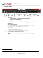
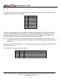
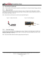
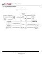
Allworx 24x
Installation Guide
-PAGE INTENTIALLY LEFT BLANK-
24x Installation Guide
Table of Contents
1
2
3
4
Installation Overview .....................................................................................................................................1
Unpacking .....................................................................................................................................................2
Chassis Views ...............................................................................................................................................3
Mechanical ....................................................................................................................................................5
4.1
Tabletop Placement ..............................................................................................................................5
4.2
Rack Mount ...........................................................................................................................................5
4.2.1
Consider When Mounting..............................................................................................................6
4.3
Wall Mount ............................................................................................................................................7
5 Electrical ........................................................................................................................................................9
5.1
Power Connection.................................................................................................................................9
5.2
Chassis Ground ....................................................................................................................................9
5.3
Power-Up Sequence .............................................................................................................................9
5.4
Safe Mode Sequence .........................................................................................................................10
6 Server Configuration....................................................................................................................................11
7 Ethernet Connectivity ..................................................................................................................................12
8 Analog Telephony........................................................................................................................................13
9 T1 ................................................................................................................................................................14
10 Accessories (Optional) ................................................................................................................................15
10.1 Music-On-Hold ....................................................................................................................................15
10.2 Overhead Paging ................................................................................................................................15
10.3 Door Relay/Paging Amplifier ...............................................................................................................16
11 Configuration Example ................................................................................................................................17
12 Physical and Environmental Specifications.................................................................................................18
13 Regulatory Notices ......................................................................................................................................19
13.1 FCC Part 68 ........................................................................................................................................19
13.2 Industry Canada..................................................................................................................................19
13.3 Radio and Television Interference ......................................................................................................20
300 Main Street • East Rochester, NY 14445 • Toll Free 1-866-ALLWORX • 585-421-3850 • www.allworx.com
© 2007 InSciTek Microsystems, Inc. All rights reserved. Allworx is a registered trademark of InSciTek Microsystems. All other names may be
trademarks or registered trademarks of their respective owners.
Revised: February 7, 2007
Page i
24x Installation Guide
1
Installation Overview
Installation of the Allworx® 24x involves the following steps:
1. Unpacking
2. Mechanical Installation
3. Electrical Installation
4. Accessories Installation
5. Telephony Installation
6. Server Configuration
7. Network Installation
8. T1 Installation
Each of these steps will be described in the following sections.
300 Main Street • East Rochester, NY 14445 • Toll Free 1-866-ALLWORX • 585-421-3850 • www.allworx.com
© 2007 InSciTek Microsystems, Inc. All rights reserved. Allworx is a registered trademark of InSciTek Microsystems. All other names may be
trademarks or registered trademarks of their respective owners.
Revised: February 7, 2007
Page 1
24x Installation Guide
2
Unpacking
Open the box and carefully unpack it. Save all shipping and packaging materials. Verify all items against the
parts list shown in Table 1. If any items are missing, contact your dealer or Allworx Customer Support at 866255-9679.
Quantity
1
1
1
1
1
1
Item
Part Number
Power Cord
24x Installation Instructions
Software CD
Sheet that has 4 Rubber Feet for Table Mounts
Rack and Wall Mount Hardware Kit
7502000 (Single HDD)
7502500 (Mirrored HDD)
3000100-01
5000220-01
5100140-01
4250100-01
6000162-01
Allworx 24x Server
Table 1: Parts List
300 Main Street • East Rochester, NY 14445 • Toll Free 1-866-ALLWORX • 585-421-3850 • www.allworx.com
© 2007 InSciTek Microsystems, Inc. All rights reserved. Allworx is a registered trademark of InSciTek Microsystems. All other names may be
trademarks or registered trademarks of their respective owners.
Revised: February 7, 2007
Page 2
24x Installation Guide
3
Chassis Views
Figure 1: Front Chassis View
1
*
2
3
4
5
6
7
8
9
1
Power switch
Press & Release – Normal shutdown within a few seconds
Press & Hold – Forced shutdown
2
Power LED – Indicates system start up activity
3
Activity LEDs – Green indicates mounted drive; blinking light indicates activity
4
USB Host Port
5
Door and paging relay port
6
RJ-45 10BaseT/100BaseTX Auto-Sensing Auto-MDI/MDIX Local Area, Wide
Area, and Demilitarized Zone (DMZ) * Network Ethernet ports.
7
T1 Ports (A/B)
8
RJ-11 Power Fail analog phone connector
9
RJ-11 loop-start FXO for central office connection (Ports 1-3)
10
RJ-11 FXS ports for inside extensions (Ports 4-8)
11
3.5 mm stereo audio mini jack for music-on-hold (input) and overhead paging
(output)
10
11
Future Feature
300 Main Street • East Rochester, NY 14445 • Toll Free 1-866-ALLWORX • 585-421-3850 • www.allworx.com
© 2007 InSciTek Microsystems, Inc. All rights reserved. Allworx is a registered trademark of InSciTek Microsystems. All other names may be
trademarks or registered trademarks of their respective owners.
Revised: February 7, 2007
Page 3
24x Installation Guide
Figure 2: Rear Chassis View
12
12
Air intake vent
13
Permanent ground connecting screw
14
Air exhaust vent
15
IEC Power cord connector
13
14
15
300 Main Street • East Rochester, NY 14445 • Toll Free 1-866-ALLWORX • 585-421-3850 • www.allworx.com
© 2007 InSciTek Microsystems, Inc. All rights reserved. Allworx is a registered trademark of InSciTek Microsystems. All other names may be
trademarks or registered trademarks of their respective owners.
Revised: February 7, 2007
Page 4
24x Installation Guide
4
Mechanical
4.1 Tabletop Placement
To install the Allworx 24x on a tabletop or shelf:
1. Remove the four rubber feet from the packaging.
2. Remove the paper backing from each rubber foot.
3. Turn over the chassis and place one foot at each corner on the bottom of the chassis.
4.2 Rack Mount
To mount the Allworx 24x, 1U high rack mount, inside of a standard 19 inch rack:
1. Verify that there is sufficient clearance around the server’s front and rear panels to allow power, network,
and telephony connections.
2. Place the brackets so that the smaller face of the bracket extends away from the front of the unit to
accommodate installation into the rack (See Figure 3).
3. Install the mounting brackets on each side of the server chassis using the four 6-32 flat head screws.
4. Proceed to the Power Connection (Section 5.1) instructions and perform the steps appropriate for your
installation before placing the system into the rack.
5. Install the server into the rack using appropriate hardware.
Figure 3: Rack Mount Bracket Installation
300 Main Street • East Rochester, NY 14445 • Toll Free 1-866-ALLWORX • 585-421-3850 • www.allworx.com
© 2007 InSciTek Microsystems, Inc. All rights reserved. Allworx is a registered trademark of InSciTek Microsystems. All other names may be
trademarks or registered trademarks of their respective owners.
Revised: February 7, 2007
Page 5
24x Installation Guide
4.2.1 Consider When Mounting
•
Elevated Operating Ambient - If installed in a closed or multi-unit rack assembly, the operating ambient
temperature of the rack environment may be greater than room ambient. Therefore, consideration
should be given to installing the equipment in an environment compatible with the maximum ambient
temperature (40°C).
•
Reduced Air Flow - Installation of the equipment in a rack should be such that the amount of air flow
required for safe operation of the equipment is not compromised.
•
Mechanical Loading - Mounting of the equipment in the rack should be such that a hazardous condition
is not achieved due to uneven mechanical loading.
•
Circuit Overloading - Consideration should be given to the connection of the equipment to the supply
circuit and the effect that overloading of the circuits might have on overcurrent protection and supply
wiring. Appropriate consideration of equipment nameplate ratings should be used when addressing this
concern.
•
Reliable Earthing - Reliable earthing of rack-mounted equipment should be maintained. Particular
attention should be given to supply connections other than direct connections to the branch circuit (e.g.
use of power strips).
300 Main Street • East Rochester, NY 14445 • Toll Free 1-866-ALLWORX • 585-421-3850 • www.allworx.com
© 2007 InSciTek Microsystems, Inc. All rights reserved. Allworx is a registered trademark of InSciTek Microsystems. All other names may be
trademarks or registered trademarks of their respective owners.
Revised: February 7, 2007
Page 6
24x Installation Guide
4.3 Wall Mount
Note: For wall mount installations, discard included power cord and use only a UL listed power cord of type
SJ or SO or better.
To mount the Allworx 24x on ½” drywall:
1. Verify that there is sufficient clearance around the server’s front and rear panels to allow power, network,
and telephony connections. Place the brackets on each side of the unit so that the smaller face of the LBracket is facing down (See Figure 4).
2. Install the mounting brackets on each side of the server chassis using the four 6-32 flat head screws.
3. Use 50lb self-drilling drywall anchors rated for at least 20 lbs with screws that are either #6 or #8. Locate
two anchors that will support the upper end of the unit using the wall mount diagram. Install the anchors
per the anchor manufacturer’s recommendation. Install the mounting screws through the bracket holes
and into the anchors.
4. Tighten screws so that Allworx server is secured firmly against the wall.
Caution: The Allworx server must be securely mounted to the wall to avoid equipment damage or
personal injury.
Note: The unit must be mounted with the front facing left or right, not up or down (See Figure 5).
Figure 4: Wall Mount Bracket Installation
300 Main Street • East Rochester, NY 14445 • Toll Free 1-866-ALLWORX • 585-421-3850 • www.allworx.com
© 2007 InSciTek Microsystems, Inc. All rights reserved. Allworx is a registered trademark of InSciTek Microsystems. All other names may be
trademarks or registered trademarks of their respective owners.
Revised: February 7, 2007
Page 7
24x Installation Guide
Figure 5: Wall Mount Orientation
Correct Orientation
Wrong Orientation
300 Main Street • East Rochester, NY 14445 • Toll Free 1-866-ALLWORX • 585-421-3850 • www.allworx.com
© 2007 InSciTek Microsystems, Inc. All rights reserved. Allworx is a registered trademark of InSciTek Microsystems. All other names may be
trademarks or registered trademarks of their respective owners.
Revised: February 7, 2007
Page 8
24x Installation Guide
5
Electrical
5.1 Power Connection
Warning: Failure to follow these steps may result in equipment damage, personal injury, and a voided
product warranty.
Insert the female end of the power cord into the receptacle on the rear of the unit. Connect the other end to
the power source. The product is rated 115/230 VAC, 1/0.7A, and 50/60Hz. The Allworx server will
automatically begin to power up once the power has been stable for a few seconds. This is part of the design
to automatically boot up after a power failure.
5.2 Chassis Ground
Warning: Failure to follow these steps may result in equipment damage, personal injury, and a voided
product warranty.
To help prevent electrical shock, the separate protective earthing terminal, located next to the power jack on
the rear panel, must be permanently connected to earth using 18 AWG wire or larger. (See Figure 2, item 13)
5.3 Power-Up Sequence
As the Allworx server progresses through the power up sequence, the front panel lights will respond as shown
in Table 2.
Front Panel Light
Power
Activity – HD
Activity – USB
Power-Up Sequence Description
Flashes green as the power up sequence
progresses; steady green when the unit is ready.
Solid green when drive mounted; blinking light
indicates activity.
Solid green when device attached and enabled;
blinking light indicates activity.
Table 2: Front Panel Lights During Power-Up Sequence
300 Main Street • East Rochester, NY 14445 • Toll Free 1-866-ALLWORX • 585-421-3850 • www.allworx.com
© 2007 InSciTek Microsystems, Inc. All rights reserved. Allworx is a registered trademark of InSciTek Microsystems. All other names may be
trademarks or registered trademarks of their respective owners.
Revised: February 7, 2007
Page 9
24x Installation Guide
5.4 Safe Mode Sequence
With the unit powered off, press and hold the power button for more than 1 second. Release the power button
once the power light turns amber. As it progresses through the safe mode power up sequence, the front panel
lights will respond as shown in Table 3.
Front Panel Light
Power
Activity – HD
Power-Up Sequence Description
Turns amber to indicate a safe mode boot has
been initialized; Flashes green as the power up
sequence progresses; Steady amber when the
unit is in safe mode.
Off.
Table 3: Front Panel Lights During Safe Mode Sequence
300 Main Street • East Rochester, NY 14445 • Toll Free 1-866-ALLWORX • 585-421-3850 • www.allworx.com
© 2007 InSciTek Microsystems, Inc. All rights reserved. Allworx is a registered trademark of InSciTek Microsystems. All other names may be
trademarks or registered trademarks of their respective owners.
Revised: February 7, 2007
Page 10
24x Installation Guide
6
Server Configuration
The Allworx 24x provides an administrative interface to configure and administer the server. The administrative
interface is accessed using a web browser. Assuming the network settings are set to their factory defaults, the
steps to connect to this interface are:
1. Plug your PC directly into the LAN port.
2. Set up the PC’s network interface to obtain an IP address automatically (using DHCP).
3. You may need to release and renew the PC’s IP address, from Windows Command Prompt, to get an
address from the server.
4. Verify that the PC has an IP address on the 192.168.2.xxx network.
5. Open your browser and enter the server’s default URL of http://192.168.2.254:8080, or currant LAN IP
address for server.
6. When the Welcome to Allworx page appears, login using the default password of admin.
When the Home page appears, click on the Install Checklist link (on the left hand side) to bring up a new
window containing steps necessary to set up a new system. Each brief step description is followed by a link to
get to the appropriate administrative web page to execute the step. These steps are ordered to aid in a
successful configuration. Most of the web pages used to execute each step contain detailed feature
descriptions and help instructions that are required to carry out the step. Use the Allworx System
Administration Guide ** as a supplement for the information on the web pages when necessary.
If the server has been previously configured for another installation, you should restore it to its factory default
configuration. This can be done by:
1. Rebooting the server to Safe Mode by holding down the power button when the server is off, or selecting
Maintenance (on the left hand side), Restart, and Enter Safe Mode after restart.
2. Format the disk and perform a Software Update (See Allworx System Administration Guide** for
instructions).
**
Allworx System Administration Guide for the 24x can be found at www.allworx.com/downloads.asp
300 Main Street • East Rochester, NY 14445 • Toll Free 1-866-ALLWORX • 585-421-3850 • www.allworx.com
© 2007 InSciTek Microsystems, Inc. All rights reserved. Allworx is a registered trademark of InSciTek Microsystems. All other names may be
trademarks or registered trademarks of their respective owners.
Revised: February 7, 2007
Page 11
24x Installation Guide
7
Ethernet Connectivity
The Local Area Network (LAN), Wide Area Network (WAN), and Demilitarized Zone (DMZ)* data network ports
are 10BaseT/100BaseTX auto-sensing and auto-MDI/MDIX ports.
SIP phones connect to the server just as any other data network device. The phones and the server need to be
properly configured. See the Server Configuration (Section 6) for more information.
The Allworx 24x is a sophisticated network appliance that must be properly configured before being connected
to the LAN, WAN, and DMZ*.
Note: Do not plug any network or ISP service into the server without first properly configuring the server.
Failure to heed this warning may result in a disruption of network connectivity with other equipment on
the network.
After the unit is properly configured, the LAN, WAN, and DMZ* network infrastructure cables can be plugged
in. Standard RJ-45 category 5 network cables must be used.
The LED’s on the LAN, WAN, and DMZ * ports are defined in Table 4.
LED Identification
Green
Amber
State
Off
On
Blinking
Off
On
Description
No link: the network is not connected
Link: the network is successfully connected
Activity: data is being transmitted or received
Speed: 10MB/S
Speed: 100MB/S
Table 4: Network Port LED Definitions
*
Future Feature
300 Main Street • East Rochester, NY 14445 • Toll Free 1-866-ALLWORX • 585-421-3850 • www.allworx.com
© 2007 InSciTek Microsystems, Inc. All rights reserved. Allworx is a registered trademark of InSciTek Microsystems. All other names may be
trademarks or registered trademarks of their respective owners.
Revised: February 7, 2007
Page 12
24x Installation Guide
8
Analog Telephony
Caution: To reduce the risk of fire, use only 26 AWG (or larger) UL listed or CSA certified
telecommunications line cord.
The server’s analog phone connections can be used to connect Central Office (CO) lines or telephone
handsets. Table 5 below describes the ports:
RJ-11 Ports
1-3
4-8
Type
FXO (loop-start)
FXS
Description
Used to connect to Central Office (CO) lines
Telephone handsets
Table 5: Analog Telephony Ports
It is recommended that the ports be connected as follows:
•
CO Lines: Begin with port 1 and move up.
•
Telephone Handsets: Begin with port 8 and move down.
The Power Fail Phone port may be used to connect an analog phone device that is operational in the event
that the server loses power or fails. During power failure, it automatically connects to the first outside phone
line port (port 1).
Surge protection is provided internally on all telephony interfaces.
300 Main Street • East Rochester, NY 14445 • Toll Free 1-866-ALLWORX • 585-421-3850 • www.allworx.com
© 2007 InSciTek Microsystems, Inc. All rights reserved. Allworx is a registered trademark of InSciTek Microsystems. All other names may be
trademarks or registered trademarks of their respective owners.
Revised: February 7, 2007
Page 13
24x Installation Guide
9
T1
T1-A and T1-B interface pin-outs for typical service connections as shown in Table 6, may require either a
straight through cable or a cross-over cable.
Pin
1
2
3
4
5
6
7
8
Description
Receive (ring)
Receive (tip)
Not Used
Transmit (ring)
Transmit (tip)
Not Used
Not Used
Not Used
Table 6: T1 Connector Wiring
The Allworx 24x is designed for T1 “short haul” use and has a fully integrated Channel Service Unit / Data
Service Unit (CSU/DSU). An external CSU/DSU is not required and should not be used. The Allworx 24x
should be connected directly to the on-site smart jack or local T1 device using the proper cabling. Do not
connect the Allworx 24x directly to the "long haul" wire pairs exiting the building.
Note: Do not plug any network or ISP service into the server without first properly configuring the server.
Failure to heed this warning may result in a disruption of network connectivity with other equipment on
the network.
After the unit is properly configured, the T1 network infrastructure cables can be plugged in. Standard RJ-45
T1 cables must be used.
The LED’s on the T1 ports are defined in Table 7.
Green
OFF
ON
ON
ON
Amber
OFF
OFF
ON
Blinking
State Meaning
Red Alarm State – No received Signal
No Alarms or Errors – Good Lock to Line
Amber Alarm State – Remote End error
Signal Quality Problem – Error of some kind
Table 7: Network Port LED Definitions
300 Main Street • East Rochester, NY 14445 • Toll Free 1-866-ALLWORX • 585-421-3850 • www.allworx.com
© 2007 InSciTek Microsystems, Inc. All rights reserved. Allworx is a registered trademark of InSciTek Microsystems. All other names may be
trademarks or registered trademarks of their respective owners.
Revised: February 7, 2007
Page 14
24x Installation Guide
10 Accessories (Optional)
Note: A stereo splitter (not included) is required to use both Music-On-Hold and Overhead Paging collectively.
10.1
Music-On-Hold
Connect the output from your music system to the server using a Y-Adapter Audio Cable [part#: 42-2551]
(See Figure 6). Insert the 3.5mm stereo plug (See Figure 7) into the audio connector labeled Line IN/OUT on
the front panel (See Figure 1 item 11).
Note: Only the white audio channel is used for music input (See Figure 6).
Figure 6: Y-Adapter Audio Cable
Figure 7: Audio Plug Diagram
Line In
GND
10.2
Line Out
Overhead Paging
Connect the server to the input of your paging system using a Y-Adapter Audio Cable [part#: 42-2551] (See
Figure 6). Insert the 3.5mm stereo plug (See Figure 7) into the audio connector labeled Line IN/OUT on the
front panel (See Figure 1, item 11).
Note: Only the red audio channel is used for paging output (See Figure 6).
300 Main Street • East Rochester, NY 14445 • Toll Free 1-866-ALLWORX • 585-421-3850 • www.allworx.com
© 2007 InSciTek Microsystems, Inc. All rights reserved. Allworx is a registered trademark of InSciTek Microsystems. All other names may be
trademarks or registered trademarks of their respective owners.
Revised: February 7, 2007
Page 15
24x Installation Guide
10.3 Door Relay/Paging Amplifier
Unit comes with a single set of C-form relay contacts for connecting to external devices such as remote door
releases and amplifiers. The contacts are rated 30 VDC @ 1A. Connect only: SELV circuits meeting IEC
60950-1 / UL 60950-1 OR NEC Class 2 circuits
Warning: Do not exceed the contact rating.
The connector is shared with the serial port (See page 3, Figure 1, item 5). The pin-out is shown in Table 8
below.
Pin
Signal
Direction
2 (do not connect)
RX
Input
3 (do not connect)
TX
Output
5 (do not connect)
GND
-9
Relay COM
-6
Relay NC
-1
Relay NO
-Table 8: Door Relay Pin-Out
To configure the door relay/paging amplifier:
1. Open your browser and enter the URL http://192.168.2.254:8080 or current LAN IP address for the server.
Refer to Server Configuration (Section 6).
2. In the Phone System group select Paging.
3. Click Modify in the Page Amplifier area.
4. Select DB9 is connected to a Door Entry System to enable door relay or DB9 is connected to a Paging
Amplifier to enable amplifier.
5. Click Update.
To activate the door relay: Dial extension 403 from any handset connected to the system dial.
300 Main Street • East Rochester, NY 14445 • Toll Free 1-866-ALLWORX • 585-421-3850 • www.allworx.com
© 2007 InSciTek Microsystems, Inc. All rights reserved. Allworx is a registered trademark of InSciTek Microsystems. All other names may be
trademarks or registered trademarks of their respective owners.
Revised: February 7, 2007
Page 16
24x Installation Guide
11 Configuration Example
A sample Allworx 24x configuration setup is shown in the Figure 8 below:
Figure 8: Configuration Example
300 Main Street • East Rochester, NY 14445 • Toll Free 1-866-ALLWORX • 585-421-3850 • www.allworx.com
© 2007 InSciTek Microsystems, Inc. All rights reserved. Allworx is a registered trademark of InSciTek Microsystems. All other names may be
trademarks or registered trademarks of their respective owners.
Revised: February 7, 2007
Page 17
24x Installation Guide
12 Physical and Environmental Specifications
Dimensions (W x H x D)
Weight (Base Model)
Power
Temperature
Humidity
17 x 1.75 x 12 inches (43.2 x 4.4 x 30.5 cm)
9.5 lbs (4.28 kg)
115/230 VAC, 1/0.7A, 50/60Hz
0° ~ 40° C
15% ~ 90% RH, Non-condensing
Table 9: Specifications
300 Main Street • East Rochester, NY 14445 • Toll Free 1-866-ALLWORX • 585-421-3850 • www.allworx.com
© 2007 InSciTek Microsystems, Inc. All rights reserved. Allworx is a registered trademark of InSciTek Microsystems. All other names may be
trademarks or registered trademarks of their respective owners.
Revised: February 7, 2007
Page 18
24x Installation Guide
13 Regulatory Notices
13.1 FCC Part 68
This equipment complies with Part 68 of FCC rules and the requirements adopted by ACTA. On the bottom of
this equipment is a label that contains, among other information, a product identifier in the format US:
AAAEQ##TXXXX. If requested, provide this number to the telephone company.
A plug and jack to connect this equipment to the premises wiring and telephone network must comply with the
applicable FCC Part 68 rules and requirements adopted by the ACTA.
The REN is used to determine the number of devices that may be connected to a telephone line. Excessive
RENs on a telephone line may result in the devices not ringing in response to an incoming call. In most but not
all areas, the sum of RENs should not exceed five (5.0). To be certain of the number of devices that may be
connected to a line, as determined by the total RENs, contact the local telephone company. For products
approved after July 23, 2001, the REN for this product is part of the product identifier that has the format
US:AAAEQ##TXXXX. The digits represented by ## are the REN without a decimal point (e.g., 03 is a REN of
0.3). For earlier products, the REN is separately shown on the label.
If this equipment causes harm to the telephone network, the telephone company will notify you in advance that
temporary discontinuance of service may be required. But if advance notice isn't practical, the telephone
company will notify the customer as soon as possible. Also, you will be advised of your right to file a complaint
with the FCC if you believe it is necessary.
The telephone company may make changes in its facilities, equipment, operations or procedures that could
affect the operation of the equipment. If this happens, the telephone company will provide advance notice in
order for you to make necessary modifications to maintain uninterrupted service.
If trouble is experienced with this equipment, for repair or warranty information, please contact our company. If
the equipment is causing harm to the telephone network, the telephone company may request that you
disconnect the equipment until the problem is resolved.
13.2 Industry Canada
The Industry Canada label identifies certified equipment. This certification means that the equipment meets
telecommunications network protective, operation and safety requirements as prescribed in the appropriate
Terminal Equipment Technical Requirements document(s). The Department does not guarantee the
equipment will operate to the user's satisfaction. Before installing this equipment, users should ensure that it is
permissible to be connected to the facilities of the local telecommunications company. The equipment must
also be installed using an acceptable method of connection. The customer should be aware that compliance
with the above conditions might not prevent degradation of service in some situations.
Repairs to certified equipment should be coordinated by a representative designated by the supplier. Any
repairs or alterations made by the user to this equipment, or equipment malfunctions, may give the
telecommunications company cause to request the user to disconnect the equipment.
300 Main Street • East Rochester, NY 14445 • Toll Free 1-866-ALLWORX • 585-421-3850 • www.allworx.com
© 2007 InSciTek Microsystems, Inc. All rights reserved. Allworx is a registered trademark of InSciTek Microsystems. All other names may be
trademarks or registered trademarks of their respective owners.
Revised: February 7, 2007
Page 19
24x Installation Guide
Users should ensure for their own protection that the electrical ground connections of the power utility,
telephone lines and internal metallic water pipe system, if present, are connected together. This precaution
may be particularly important in rural areas.
Caution: Users should not attempt to make such connections themselves, but should contact the
appropriate electric inspection authority, or electrician, as appropriate.
NOTICE: This equipment meets the applicable Industry Canada Terminal Equipment Technical Specifications.
This is confirmed by the registration number. The abbreviation, IC, before the registration number signifies that
registration was performed based on a Declaration of Conformity indicating that Industry Canada technical
specifications were met. It does not imply that Industry Canada approved the equipment.
AVIS: Le présent matériel est conforme aux spécifications techniques d’Industrie Canada applicables au
matériel terminal. Cette conformité est confirmée par le numéro d'enregistrement. Le sigle IC, placé devant le
numéro d'enregistrement, signifie que l’enregistrement s’est effectué conformément à une déclaration de
conformité et indique que les spécifications techniques d'Industrie Canada ont été respectées. Il n’implique pas
qu’Industrie Canada a approuvé le matériel.
NOTICE: The Ringer Equivalence Number (REN) for this terminal equipment is 0.1. The REN assigned to
each terminal device provides an indication of the maximum number of terminals allowed to be connected to a
telephone interface. The termination on an interface may consist of any combination of devices subject only to
the requirement that the sum of the Ringer Equivalence Numbers of all the devices does not exceed 5.
AVIS : L'indice d'équivalence de la sonnerie (IES) du présent matériel est de 0.1. L'IES assigné à chaque
dispositif terminal indique le nombre maximal de terminaux qui peuvent être raccordés à une interface
téléphonique. La terminaison d'une interface peut consister en une combinaison quelconque de dispositifs, à la
seule condition que la somme d'indices d'équivalence de la sonnerie de tous les dispositifs n'excède pas 5.
13.3 Radio and Television Interference
This equipment has been tested and found to comply with the limits for a Class B digital device, pursuant to
Part 15 of the FCC rules. These limits are designed to provide reasonable protection against harmful
interference in a residential installation. This equipment generates uses and can radiate radio frequency
energy and, if not installed and used in accordance with the instructions, may cause harmful interference to
radio communications. There is no guarantee, however, that interference will not occur in a particular
installation. If this equipment does cause harmful interference to radio or television reception, which can be
determined by turning the equipment off and on, the user is encouraged to try to correct the interference by
one or more of the following measures:
•
Reorient or relocate the receiving antenna.
•
Increase the separation between the equipment and the receiver.
•
Connect the equipment into an outlet on a circuit different from that to which the receiver is connected.
•
Consult the dealer or an experienced radio/TV technician for help.
300 Main Street • East Rochester, NY 14445 • Toll Free 1-866-ALLWORX • 585-421-3850 • www.allworx.com
© 2007 InSciTek Microsystems, Inc. All rights reserved. Allworx is a registered trademark of InSciTek Microsystems. All other names may be
trademarks or registered trademarks of their respective owners.
Revised: February 7, 2007
Page 20
24x Installation Guide
You may also find helpful the following booklet, prepared by the FCC: "How to Identify and Resolve Radio-TV
Interference Problems.” This booklet is available from the U.S. Government Printing Office, Washington D.C.
20402.
Changes and Modifications not expressly approved by the manufacturer or registrant of this equipment can
void your authority to operate this equipment under Federal Communications Commissions rules.
This digital apparatus does not exceed the Class B limits for radio noise emissions from digital apparatus set
out in the Radio Interference Regulations of the Canadian Department of Communications.
Le présent appareil numérique n'emet pas de bruits radioélectriques depassant les limites applicables aux
appareils numérique de la class B préscrites dans le Règlement sur le brouillage radioélectrique édicte par le
Ministere des Communications du Canada.
300 Main Street • East Rochester, NY 14445 • Toll Free 1-866-ALLWORX • 585-421-3850 • www.allworx.com
© 2007 InSciTek Microsystems, Inc. All rights reserved. Allworx is a registered trademark of InSciTek Microsystems. All other names may be
trademarks or registered trademarks of their respective owners.
Revised: February 7, 2007
Page 21