1
COURIER
HIGH SPEED MODEM
Courier V.34 Dual Standard Fax
USER MANUAL
COURIER HIGH SPEED MODEMS
HOW TO USE THIS MANUAL
This manual contains operating instructions for Courier Dual
Standard V.34 and Courier V.34 modems.
These modems have many similar features except for the
signaling they use to connect with remote modems at high
speeds: V.32/V.32 terbo, HST, V.FC, or V.34. Courier HST Dual
Standard modems use any type of signaling, depending on the
type of remote modem. V.34 modems can connect at rates up to
28.8K bps.
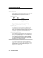
Below is a brief description of the manual's contents.
•
•
•
•
•
•
•
•
•
•
•
•
•
•
•
•
•
ii
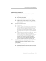
Chapter 1Operating and Compatibility Features
Chapter 2Installation
Chapter 3Internal Modem Installation
Chapter 4Data Mode Commands
Chapter 5Fax Mode and Call Selection
Chapter 6Queries and Help commands to display
current settings, operational summaries, and other data
Background information on protocols, error control,
and throughput
Summaries and tables
Alphabetical Command Summary
Dial Security operations
Troubleshooting
Online synchronous and V.25 bis synchronous
operations
Additional features such as HST Cellular and
voice/data switch
Procedures for modem testing
Procedures for upgrading your modem via software
downloads
Glossary
Warranty/Service/Certification information
How to Use This Manual
COURIER HIGH SPEED MODEMS
A NOTE ON COMMUNICATIONS SOFTWARE
If you're using a computer rather than a terminal, you need
communications software. Many brands are available, all of
which are based on the modem's AT command set.
Some users prefer their communications software to take
control of the modem, and are more comfortable with a
program that makes the modem almost transparent. Others
prefer a program that allows them to use the modem's AT
command set sometimes, and their software at other times,
depending on the task at hand. Review at least Chapter 4 so
that you have a basic understanding of the modem's requirements and operation.
How to Use This Manual
iii
U.S. Robotics, the U.S. Robotics logo, and HST are registered
trademarks of U.S. Robotics, Inc. Courier HST Dual Standard
Fax, Courier V.32 terbo Fax, Total Control, and Adaptive Speed
Leveling (ASL) are trademarks of U.S. Robotics, Inc. V.Fast
Class and V.FC are trademarks of Rockwell International. Any
trademarks, tradenames, service marks or service names owned
or registered by any other company and used in this manual are
the property of their respective companies.
COURIER HIGH SPEED MODEMS
TABLE OF CONTENTS
How to Use this Manual
Table of Contents
Limited Warranty
FCC Registration Numbers
IC (Industry Canada)
Connecting to the Telephone Company
Radio and Television Interference
For Canadian Modem Users
ii
v
ix
x
x
x
x
xi
PART I. INSTALLATION AND OPERATION
Chapter 1
Features and Compatibility
Introduction
Features
Compatibility
Fax Standards
Other Compatibility Features
Chapter 2
External Modem Set-Up
Switches on the Modem
Front Panel Indicators on the Modem
Package Components
What You Need
An RS-232 Cable
Communications Software. . .
Telephone Adapter. . .
You Should. . .
Refer to Appendix F. . .
Refer to Appendix G. . .
Installing the Modem
Testing the Installation
Chapter 3
Internal Modem Setup
Package Components
What You Need
Communications Software. . .
A Telephone Adapter
You Should. . .
Refer to Appendix F. . .
Refer to Appendix G. . .
Before Installing the Modem
Select a Serial Port
Select an Interrupt Request (IRQ)
1-1
1-1
1-6
1-7
1-7
2-1
2-2
2-2
2-2
2-2
2-3
2-3
2-3
2-3
2-4
2-4
2-6
3-1
3-1
3-1
3-2
3-2
3-2
3-2
3-2
3-3
3-4
Table of Contents
v
COURIER HIGH SPEED MODEMS
Reset the Jumpers
Set DIP Switches
Installing the Modem
Testing the Installation
Chapter 4
Data Mode Command Summary
Command Set Usage
Basic Commands
Dialing/Answering
Dialing
Dial Options
Cancel Dialing
Store Phone Numbers
Redialing
Answer Mode
Hanging Up
Setting/Using Defaults
Customizing NVRAM
Resetting the Modem
Configuration
Echo/Speaker
Result Codes
Additional Result Code Sets
Modulation
Error Control/Data Compression
Data Rates
RS-232 Signal Operations
Flow Control
S-Registers
Inquiry and Help
Testing
International Calls (&Gn, &Pn)
Miscellaneous Commands
Chapter 5
Fax Operations and Call Detection
Fax Operations
Notes to Programmers
Call Detection
Chapter 6
Queries and Help Screens
User Inquiries (In)
S-Register Query (Sr?)
Phone Number Query (&Zn?)
vi
Table of Contents
3-5
3-6
3-6
3-8
4-1
4-3
4-4
4-4
4-4
4-6
4-7
4-7
4-8
4-9
4-11
4-12
4-13
4-13
4-13
4-14
4-17
4-19
4-19
4-21
4-23
4-24
4-29
4-30
4-30
4-30
4-31
5-1
5-3
5-4
6-1
6-7
6-7
COURIER HIGH SPEED MODEMS
Last-Dialed Number Inquiry (DL?)
Stored Command String Query (&ZC?)
Help Screens
Stop/Restart Display
Cancel Display
Basic Command Set ($)
Extended Command Set (&$)
Dialing (D$)
S-Register Functions (S$)
Percent Commands (%$)
6-8
6-8
6-8
6-8
6-8
6-8
6-9
6-10
6-10
6-11
PART II. REFERENCE
Appendix A
Link Negotiation (Handshaking)
and Error Control
V.34 Handshaking
V.Fast Class (V.FC) Handshaking
U.S. Robotics V.32 terbo to U.S. Robotics V.32 terbo
Other V. Protocol Operations
Dual Standard Handshaking
Error Control and Throughput
V.42 Handshaking
MNP Handshaking
Data Compression
Flow Control
Throughput Guidelines
Typical Throughput
Appendix B
Summaries and Tables
The RS-232 Interface
Front Panel Indicators
DIP Switch Summary
Default Settings
Factory Templates
&F1 Hardware Flow Control (Default)
&F2 Software Flow Control
&F3 HST Cellular
&F0 No Flow Control
NVRAM Options
S-Register Summary
ASCII Chart
A-1
A-2
A-2
A-3
A-4
A-4
A-5
A-5
A-5
A-6
A-7
A-8
B-2
B-5
B-7
B-9
B-10
B-11
B-12
B-13
B-14
B-15
B-28
Table of Contents
vii
COURIER HIGH SPEED MODEMS
Appendix C
Alphabetical Command Summary
Command Set Usage
Basic Command Set
Ampersand (&) Command Set
Percent (%) Command Sets
Appendix D
Dial Security/Remote Access
Dial Security
Remote Access
C-1
C-2
C-9
C-18
D-1
D-10
Appendix E
Troubleshooting
Appendix F
Synchronous and Leased Line Operations
Synchronous
V.25 bis
Online synchronous
Dedicated Line and Leased Line Operations
Appendix G
Additional Operations
Cellular Operations
Voice/Data (External Modems Only)
Hewlett Packard 3000 Installations
MI/MIC Operations (External Modems Only)
Appendix H
Modem Testing
Testing with &T
Ending a Test&T0, S18
Analog Loopback&T1, &T8
&T2
Digital Loopback&T3
&T4, &T5
Remote Digital Loopback&T6, &T7
Testing with Register S16
Analog LoopbackS16=1D
Dial TestS16=2
Test PatternS16=4
Remote Digital LoopbackS16=8
Appendix I
Software Upgrades
Appendix J
Glossary
Appendix K
Technical Specifications
Index
viii
Table of Contents
F-1
F-4
F-9
F-15
G-2
G-4
G-8
G-9
H-1
H-1
H-2
H-4
H-4
H-5
H-5
H-8
H-9
H-9
H-10
H-10
COURIER HIGH SPEED MODEMS
LIMITED WARRANTY
U.S. Robotics, Inc., warrants to the original consumer or other
end user purchaser that this product is free from defects in
materials or workmanship for a period of two years from the
date of purchase. During the warranty period, and upon proof
of purchase, the product will be repaired or replaced (with the
same or similar model) at our option, without charge for either
parts or labor. This warranty shall not apply if the product is
modified, tampered with, misused, or subjected to abnormal
working conditions.
REPAIR OR REPLACEMENT AS PROVIDED UNDER THIS
WARRANTY IS THE EXCLUSIVE REMEDY OF THE PURCHASER. THIS WARRANTY IS IN LIEU OF ALL OTHER
WARRANTIES, EXPRESS OR IMPLIED, INCLUDING ANY
IMPLIED WARRANTY OF MERCHANTABILITY OR FITNESS
FOR A PARTICULAR USE OR PURPOSE, AND U.S.
ROBOTICS SHALL IN NO EVENT BE LIABLE TO
PURCHASER FOR INDIRECT OR CONSEQUENTIAL
DAMAGES OF ANY KIND OR CHARACTER.
Some states do not allow the exclusion or limitation of
incidental or consequential damages or allow limitations on
how long an implied warranty lasts, so the above limitations or
exclusion may not apply to you. This warranty gives you
specific legal rights. You may also have other rights which vary
from state to state.
Should you encounter problems in operating this device, follow
the instructions in Appendix E in Part II of this manual. The
appendix contains solutions to operating problems as well as
procedures to follow if there is an apparent modem
malfunction.
Warranty Information
ix
COURIER HIGH SPEED MODEMS
FCC REGISTRATION
FCC68: CJEUSA-73130-FA-E
RINGER EQUIVALENCE: 0.4B
FCC15:
CJE-0263 (External modem)
CJE-158-243 (Internal modem)
CJE-0151-243 (Daughterboard)
IC (INDUSTRY CANADA)
This digital apparatus does not exceed the Class B limits for
radio noise emissions from digital apparatus set out in the radio
interference regulations of Industry Canada (formerly Canadian
Department of Communications).
Le present appareil numerique n'emet pas de bruits radioelectriques depassant les limites applicables aux appareils
numeriques de la classe B prescrites dans le Reglement sur le
brouillage radioelectrique edicte par le ministere des
Communications du Canada.
CONNECTING TO THE TELEPHONE COMPANY
It is not necessary to notify the telephone company before
installing the modem. However, the telephone company may
request the telephone number(s) to which the Courier is
connected and the FCC information printed above.
If the modem is malfunctioning, it may affect the telephone
lines. In this case, disconnect the modem until the source of the
difficulty is traced. Do not use the modem on party or coin
telephone lines.
RADIO AND TELEVISION INTERFERENCE
This equipment generates and uses radio frequency energy,
and, if not installed and used properly in strict accordance with
the manufacturer's instructions, may cause interference to radio
and television reception. Courier high speed modems have
been tested and found to comply with the limits for a Class B
computing device in accordance with the specifications in Part
x
Warranty Information
COURIER HIGH SPEED MODEMS
15 of FCC rules, which are designed to provide reasonable
protection against such interference in a residential installation.
However, there is no guarantee that interference will not occur
in a particular installation. If this device does cause interference
to radio or television reception, which you can determine by
monitoring reception when the modem is on and off, try to
correct the problem with one or more of the following
measures.
•
Reorient the receiving antenna.
•
Relocate the computer with respect to the receiver.
•
Relocate the computer and/or the receiver so that they
are on separate branch circuits.
If necessary, consult your dealer or an experienced radio/
television technician for additional suggestions. You may find
the following booklet, prepared by the Federal Communications
Commission, helpful:
How to Identify and Resolve Radio-TV Interference
Problems
Stock No. 004-000-0345-4
U.S. Government Printing Office
Washington, DC 20402
In accordance with Part 15 of the FCC rules, any modification to
or tampering with this device that causes harmful interference
to others may be reason for prohibiting future operation.
FOR CANADIAN MODEM USERS
The Industry Canada (formerly DOC) label identifies certified
equipment. This certification means that the equipment meets
certain telecommunications network protective, operational,
and safety requirements. The department does not guarantee
the equipment will operate to a user's satisfaction.
Before installing this equipment, make sure you are permitted
to connect it to the facilities of the local telecommunications
company. You must also install the equipment using an
acceptable method of connection. In some cases, you may also
extend the company's inside wiring for single line individual
service by means of a certified connector assembly (telephone
extension cord). You should be aware, however, that
Regulatory Information
xi
COURIER HIGH SPEED MODEMS
compliance with the above conditions may not prevent
degradation of service in some situations.
Repairs to certified equipment should be made by an
authorized Canadian maintenance facility designated by the
supplier. Any repairs or alterations made by a user to this
equipment, or equipment malfunctions, may give the
telecommunications company cause to request the user to
disconnect the equipment.
For your own protection, make sure that the electrical ground
connections of the power utility, telephone lines, and internal
metallic water pipe system, if present, are connected together.
This precaution may be particularly important in rural areas.
WARNING: Do not attempt to make such connections
yourself; contact the appropriate electric inspection authority or
electrician.
Courier High Speed Modems Load Number: 5
The Load Number (LN) assigned to each terminal device
denotes the percentage of the total load to be connected to the
telephone loop used by the device, without overloading. The
termination on a loop may consist of any combination of
devices, subject only to the requirement that the total of the
Load Numbers of all the devices not exceed 100.
xii
Regulatory Information
COURIER HIGH SPEED MODEMS
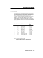
CHAPTER 1. FEATURES AND COMPATIBILITY
INTRODUCTION
Congratulations! The Courier modem you've purchased represents powerful, advanced electronic design that offers exceptional reliability, compatibility and flexibility at all standard
rates up to 28,800 or 28.8K bits per second (bps). The
transmission rate between the computer and modem,
depending on your equipment and software support, can be as
high as 115.2K bps.
Features
The following features and capabilities assure you of superior
reliability and performance.
Connections up to 28.8K bps
With the V.34 standard and the V.Fast Class modulation
scheme, two modems can connect at rates up to 28.8K bps,
twice as fast as the rates of standard ITU-T (formerly CCITT)
V.32 bis modems, which are limited to calls of 14.4K bps or less.
Software Upgrades
Courier high speed modems are now software upgradable,
allowing you quick, easy access to the latest advances in data
communication technology. See Appendix I.
Quick Connect
In V.32 terbo mode, Courier high speed modems can handshake
and start transmitting much faster than typical training times
that range between 9 and 18 seconds for other modems.
Features and Compatibility
1-1
COURIER HIGH SPEED MODEMS
Universal Connect
Courier high speed modems automatically detect and connect
at the fastest available speed.
Adaptive Speed Leveling (ASL)
Like most high speed modems, Courier modems fall back to the
next lower speed—for example, 19.2K, then 16.8K in V.terbo
mode—if poor line conditions warrant. In addition, Courier
V.32 bis, and V.32 terbo modems detect improved line conditions
and shift upward again to the next higher speed. both transmit
and receive channels adapt independently, each detecting and
adjusting to line conditions. ASL keeps the modems online,
always operating at the highest possible speed, and constantly
ensuring data integrity.
Fax Capability
You can use your modem with Class 1 or Class 2.0 facsimile
software to exchange faxes with millions of Group III fax
machines worldwide. See Chapter 5.
Error ControlV.42/MNP
Data integrity is ensured when the modems connect with
remote modems that use the V.42 (LAPM), HST, or MNP error
control protocols. Error control is available on calls at 1200 bps
and above.
Data CompressionV.42 bis/MNP5
Data compression enables potential throughput of up to 115.2K
bps on 28.8K bps connections. Couriers connecting under V.42
or HST error control use V.42 bis compression. Couriers
connecting under MNP error control use MNP Level 5
compression. Typical throughput of text and other types of files
using V.42 bis is provided in Appendix A.
1-2
Features and Compatibility
COURIER HIGH SPEED MODEMS
Flow Control/Variable Serial Port Rates
Flow control, required under error control, also allows the local
serial port (DTE) rate to be set higher than the link (connection)
rate, enabling greater efficiency and throughput. If your
equipment and software support high rates, data can be sent
from the computer to the modem at 115.2K, 57.6K, 38.4K or
19.2K bps, regardless of the link rate.
Voice/Data Switch
A switch on the modem's front panel allows you to change from
voice to data and back again, without issuing a command. See
Appendix G.
Stored Command String
If you don't ordinarily use voice and data in the same call, you
can assign the voice/data switch a different function that
normally requires a command, such as resetting the modem or
executing a stored command string. See Voice/Data in Appendix
G for instructions on use of the voice/data switch.
Asynchronous/Synchronous Capability
Courier high speed modems operate synchronously as well as
asynchronously. A personal computer equipped with a
synchronous interface adapter can call computers that use
standard synchronous protocols. See Appendix F for more
information.
Synchronous Operations with V.25 bis
Used with computers that have a synchronous card and port,
Courier high speed modems combine the power of older
modems and automatic calling units in the mainframe
environment. They make synchronous connections by utilizing
V.25 bis, character-oriented (similar to BISYNC) and HDLC
protocols. See Appendix F for more information.
Dial Security
With Dial Security, you will be able to prevent unauthorized
access to a system with the use of Autopass, Prompting, and
Dialback. See Appendix D for more information.
Features and Compatibility
1-3
COURIER HIGH SPEED MODEMS
Programmable Nonvolatile Memory
You can tailor your own default settings and store them in nonvolatile random access memory (NVRAM). Each time the
Courier is powered on or reset, it operates at the settings you've
specified. See Chapter 4, Appendix B, and Appendix C.
Link Rate Negotiation
The Courier automatically lowers its link rate to match a lower
rate of a remote modem, in both Originate and Answer Modes,
allowing connections with a wide range of installed modems.
Link Diagnostics
After each call, you can display a Link Diagnostics screen containing information about the last call, including the number of
data characters transferred, line statistics, the call's rate and the
reason the call was disconnected. See Chapter 6.
Modem Diagnostics
ITU-T V.54 loopback testing with the &T command options, and
earlier Courier Register S16 test options are available. The
modem performs three loopback tests: analog, digital, and
remote digital. See Appendix H for information.
Inactivity Timer
You can set the modem to automatically hang up after a specified number of minutes if there is no activity on the phone line.
See Register S19 in Appendix B.
Call Duration Reporting
The modem records the duration of your calls in hours,
minutes, and seconds. This feature enables you to display and
print an audit of your calling activities. You can optionally use
the modem clock as a real-time clock. See the I3 and I6 screens
in Chapter 6 and the K command in Chapter 4 and Appendix C.
Call Progress Detection
An optional set of result codes (screen messages) lets you know
when a line is busy, a person rather than a modem has
answered the phone, there is no dial tone, or the distant phone
is ringing.
1-4
Features and Compatibility
COURIER HIGH SPEED MODEMS
Modem Settings Displays
On command, the modem displays its current settings, a handy
way to check your transmission rate, S-Registers and other
operational controls. The modem also displays the defaults
stored in nonvolatile memory as well as its default
configuration templates. See Chapter 6.
HELP Screens
The modem displays screens that summarize the command sets,
Dial command options, and S-Register functions. See Chapter
6.
Bottom Panel Reference
Command summaries and other information are printed on the
bottom of the modem case. A Dual In-Line Package (DIP)
switch guide makes it easy to tailor the switch settings to your
terminal or software requirements.
Dialing the Last-Dialed Number
The modem has a buffer that stores each dialed number until it
is cleared by another Dial command. A few keystrokes cause
the modem to redial the number in the buffer without your
having to enter the number again. See the DL command in
Appendix C.
Automated Redialing
You can put the modem into Repeat Mode to continuously
redial if a previous dial attempt fails to connect. This is especially useful in dialing services whose lines are often busy. See
Chapter 4.
Quote Mode
Set the modem to Quote Mode if you want it to dial an alphabetic acronym instead of a numeric number. See Chapter 4.
Features and Compatibility
1-5
COURIER HIGH SPEED MODEMS
COMPATIBILITY
The Courier adheres to the following modulation schemes and
standards, ensuring compatibility with a wide base of installed
modems. Unless otherwise indicated, Dual Standard V.34
modems conform to the listed standards.
NOTE: The International Telecommunication Union (ITU-T)
was formerly the International Telegraph and Telephone
Consultative Committee (CCITT).
1-6
ITU-T V.34
28.8K/26.4K/24K/21.6K/19.2K/16.8K/14.4K/12K/
9600/7200/4800/2400 bps
V.FC
28.8K/26.4K/24K/21.6K/19.2K/16.8K/14.4K bps
V.32 terbo
21.6K/19.2K/16.8K/14.4K/12K/9600/
7200/4800 bps
HST
16.8K/14.4K/12K/9600/7200/4800 bps (Dual
Standard modems in HST mode with ASL up
to 21.6K bps)
HST Cellular
Cellular connections at 12K/9600/7200/
4800/2400/1200/300 bps (Dual Standard
modems in HST mode)
ITU-T V.32 bis
14.4K/12K/9600/7200/4800 bps
ITU-T V.32
9600/4800 bps
ITU-T V.22 bis
2400 bps
Bell 212A
1200 bps (also V.22)
ITU-T V.23
1200 bps with 75 bps back channel (some U.K.
and European phone systems)
ITU-T V.25
Answer sequence for calls originating outside
the U.S. and Canada
ITU-T V.25 bis
For synchronous communications using
HDLC and character-oriented protocols
Bell 103
300 bps (ITU-T V.21 optional)
ITU-T V.42
LAPM error control, 1200 bps and higher
ITU-T V.42 bis
Data compression, 1200 bps and higher
Features and Compatibility
COURIER HIGH SPEED MODEMS
MNP
Levels 2, 3 and 4 error control, level 5 data
compression, 1200 bps and higher
ITU-T V.54
Analog, digital and remote digital loopback
testing
Fax Standards
The Courier modem provides Group III-compatibility when
combined with Class 1 or Class 2.0 fax software. In addition,
the modem adheres to the following standards.
TIA/EIA-578
Service Class 1 Asynchronous Facsimile
DCE Control Standard
TIA/EIA-592
Service Class 2.0 Asynchronous Facsimile
DCE Control Standard
ITU-T V.17
14.4K/12K bps
ITU-T V.29
9600/7200 bps
ITU-T V.27 ter
4800/2400 bps
ITU-T V.21
300 bps
Other Compatibility Features
Other compatibility features include the following standards
and certification:
•
Can be used with any computer or terminal that is compatible with the RS-232 standard interface.
•
Can be used with any computer or terminal that uses
ASCII, the standard character code supported by most
equipment manufacturers.
•
Is fully FCC- and IC-certified for the uses described in
this manual.
Features and Compatibility
1-7
COURIER HIGH SPEED MODEMS
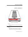
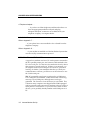
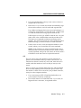
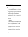
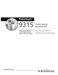
CHAPTER 2. MODEM SET UP
HS
AA
CD
OH
RD
SD
TR
MR
RS
CS
SYN
V.34 Fax with
ARQ/ VOICE/DATA
V.FC and V.32 bis
FAX
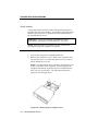
Figure 2.1—Courier V.34 Modem
Reminder
To prevent overheating, do not cover the vents on the top of the
modem case.
SWITCHES ON THE MODEM
Voice/Data
This push-button switch is used primarily to switch between
voice and data communications during a call. Detailed
instructions are in the Voice/Data Calls section in Appendix G.
External Modem Set Up
2-1
COURIER HIGH SPEED MODEMS
Volume Control
This is a slide switch underneath the right side panel of the
modem, near the front corner. Sliding it toward the front of the
modem increases the modem speaker’s volume; sliding it
toward the rear of the modem decreases the volume.
FRONT PANEL INDICATORS ON THE MODEM
The modem has twelve status lights, or LEDs. See Appendix B
for descriptions of their operations.
PACKAGE COMPONENTS
Your Courier modem package contains the following items:
•
•
•
•
•
The modem you purchased: Courier V.34
An RJ11C phone cord
A power adapter
Fax software and manual
A Quick-Reference card
WHAT YOU NEED
The Courier modem has minimal operational requirements. Be
sure to read the information in the front of this manual about
radio and television interference and connecting to the phone
company. In addition, you should be aware of the following
requirements.
An RS-232 Cable
You need an RS-232 cable to connect the modem to your computer or terminal. Use a shielded cable to ensure minimal interference with radio and television reception.
NOTES:
•
2-2
Refer to Appendix B for a listing of RS-232 pin
assignments required to operate the modem. Be sure to
check the appendix if you're not sure what type of cable
you need, or if you're building your own.
External Modem Set Up
COURIER HIGH SPEED MODEMS
•
If your machine has other than a 25- or 9-pin port, check
your computer documentation or consult your dealer to
find out what type of RS-232 connector is required.
WARNING: If you're planning to use the high speed
computer-to-modem rates of 115.K, 57.6K or 38.4K bps, follow
the instructions concerning the RS-232 cable in Appendix B.
The guidelines there will help you to avoid signal degradation
at very high speeds.
Communications Software. . .
. . .if the modem is attached to a computer instead of a terminal.
The software uses the modem's AT command set to control
many communications functions, including configuring the
modem, dialing, and answering calls, and also enables the
transfer of files and other operations.
Some users prefer their communications software to take
control of the modem, and are more comfortable with a
program that makes the modem almost transparent. Others
prefer a program that allows them to use the modem's AT
command set sometimes, and their software at other times,
depending on the task at hand.
Review Chapter 4 so that you have a basic understanding of the
modem's requirements and operation.
Telephone Adapter. . .
. . .if you have an older telephone installation that does not
have the appropriate modular wall jack and plug.
Adapters and RJ11C connectors are available from your
telephone company or computer dealer.
YOU SHOULD. . .
Refer to Appendix F. . .
. . .if your phone line is user-installed or if it is leased from the
telephone company.
External Modem Set Up
2-3
COURIER HIGH SPEED MODEMS
Refer to Appendix G. . .
. . . if your modem is installed in a Hewlett Packard system that
uses the Ack/Enq communications protocol.
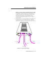
INSTALLING THE MODEM
1.
Turn off the computer or terminal and its peripheral
devices.
2.
Examine the label on the bottom of the modem. In addition
to the summaries and other information, the label contains
icons to aid in modem installation.
4.
Make sure that the modem’s power switch is OFF; press it
towards the zero in the 0/1 icon on the bottom label.
5.
Plug the power supply adapter's small connector into the
power jack at the back of the modem. Plug the adapter into
a standard 115-volt AC wall socket.
6.
Disconnect your present phone cable from the wall jack.
Plug one end of the supplied phone cable into the modem's
phone jack (refer to the bottom label). Plug the other end
into the wall jack.
If you want to keep your telephone connected for conventional calls, plug its cord into the modem’s telephone jack
(refer to the bottom label).
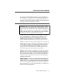
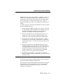
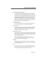
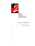
7.
Check the positions of the bank of Dual In-Line Package
(DIP) Switches located in the well at the bottom of the
modem. These switches are set at the factory to the
positions most users require.
1
2
3
4
5
6
7
8
9
10
OFF
ON
Figure 2.2—DIP Switch Factory Settings
Check your software documentation for its requirements,
particularly for DIP switches 1, 4, 5 and 6. You'll also find
descriptions of switch functions and options in Appendix B.
2-4
External Modem Set Up
COURIER HIGH SPEED MODEMS
NOTE: If you have built your own RS-232 cable and it does
not support the Data Terminal Ready (DTR) signal, set DIP
switch 1 ON, for DTR override. The override causes the
modem to operate as if the DTR signal were always ON,
and enables the modem to accept commands. Most
purchased communications software, however, requires
“normal” DTR.
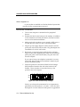
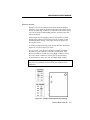
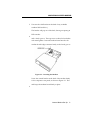
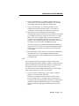
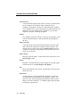
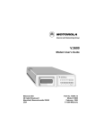
8.
The final step is to connect the modem to the computer's or
terminal's serial port with the RS-232 cable. Attach the
appropriate connectors to the modem and to the serial port.
ON/OFF
POWER
PHONE JACKS
SERIAL PORT INTERFACE
To computer
To wall outlet
To wall jack
To phone
Figure 2.3—Cabled Courier Modem
External Modem Set Up
2-5
COURIER HIGH SPEED MODEMS
TESTING THE INSTALLATION
Use the following procedures to verify that your modem is
working properly.
1.
Turn on your computer or terminal. Then turn the
Courier's power switch ON. The following front panel
indicators, or LEDs, will light up on the modem.
CD Carrier Detect, if you have set DIP switch 6 ON,
enabling the CD override
TR
Data Terminal Ready, if you have set DIP switch 1
ON, enabling the DTR override
MR Modem Ready/Power ON
CS
Clear to Send
2.
If you're using a personal computer, load your software to
start the program. Set your terminal or software to 19.2K
bps or 9600 bps. In addition, set a word length of either 7
bits plus 1 parity bit, or 8 bits with no parity—it doesn't
matter which at this time—and 1 Stop bit. Set the software
to use the correct serial port (port through which the
modem connects to the computer).
3.
Perform the function that lets you send AT commands to
the modem, that is, puts the computer in Terminal mode.
Some communications programs do this automatically upon
loading. Others require you to display a communications or
terminal screen, type a Function key, or perform some other
operation.
Review your communications software documentation for
instructions.
4.
Send the following attention command. Type either upper
or lower case letters, not a combination, and then press the
Enter (Carriage Return) key, shown in the example below
between angle brackets. (Don't type the angle brackets.)
AT <Enter>
If everything is correct, the modem responds as follows:
OK
Go on to step 5.
2-6
External Modem Set Up
COURIER HIGH SPEED MODEMS
Troubleshooting
If your entered command is not displayed, your local echo is
OFF. To turn the local echo ON, send the modem the
following command:
ATE1 <Enter>
If double characters appear on the screen, both your modem and
software are set to local echo ON. Either set your software
to local echo OFF, or turn the modem's echo OFF with the
following command:
ATE0 <Enter>
If no OK appears on your screen after you completed Step 4,
review the following checkpoints:
a.
Make sure you type all upper or lower case letters and
press <Enter>.
b. Check to see that you set your communications
software to the correct serial port. The correct serial
port is the port through which the modem is connected
to the computer.
c.
Make sure your software has put the computer in
Terminal mode, so that you can send the modem
commands. Then review Step 4, on the previous page.
d. Be sure that DIP switches 1 and 6 are set ON or OFF
according to your terminal or software requirements.
The table in Appendix B explains each function, and
you may also need to review your terminal or
communications software documentation.
e.
If you set DIP switch 8 OFF, for Dumb mode, reset the
modem to Smart mode: set DIP switch 8 to ON.
f.
The modem is shipped with DIP switch 3 ON, enabling
the result codes. If DIP switch 3 is OFF, set it to the ON
position. Then initiate the new switch setting with the
following reset command:
ATZ <Enter>
External Modem Set Up
2-7
COURIER HIGH SPEED MODEMS
5.
As a final check, make sure the modem gets a dial tone.
Type the following Dial command:
ATD <Enter>
On receipt of the command, the modem goes off hook and
waits for a dial tone. The OH indicator lights up, and you'll
hear the dial tone from the modem's speaker. To cancel the
operation, press any key.
Troubleshooting
If you don't hear the dial tone, first increase the volume by
sliding the volume control switch towards the front of the
modem. If that doesn't work, check to see that the phone
cable from the wall jack is connected to the correct jack on
the modem (See Figure 2.3). If necessary, reconnect the
phone cable correctly. Then try the Dial command again,
ATD <Enter>.
2-8
External Modem Set Up
COURIER HIGH SPEED MODEMS
CHAPTER 3. INTERNAL MODEM SET UP
PACKAGE COMPONENTS
Your Courier modem package contains the following items:
•
•
•
•
•
The modem you purchased: Courier V.34
An RJ11C phone cord
A power adapter
Fax software and manual
A Quick-Reference card
WHAT YOU NEED
The Courier modem has minimal operational requirements. Be
sure to read the information in the front of this manual about
radio and television interference and connecting to the phone
company. In addition, you should be aware of the following
requirements.
Communications Software. . .
. . .if the modem is attached to a computer instead of a terminal.
The software uses the modem's AT command set to control
many communications functions, including configuring the
modem, dialing, and answering calls, and also enables the
transfer of files and other operations.
Some users prefer their communications software to take
control of the modem, and are more comfortable with a
program that makes the modem almost transparent. Others
prefer a program that allows them to use the modem's AT
command set sometimes, and their software at other times,
depending on the task at hand.
Review Chapter 4 so that you have a basic understanding of the
modem's requirements and operation.
Internal Modem Set Up
3-1
COURIER HIGH SPEED MODEMS
A Telephone Adapter. . .
. . .if you have an older telephone installation that does not
have the appropriate modular wall jack and plug.
Adapters and RJ11C connectors are available from your
telephone company or computer dealer.
YOU SHOULD. . .
Refer to Appendix F. . .
. . .if your phone line is user-installed or if it is leased from the
telephone company.
Refer to Appendix G. . .
. . . if your modem is installed in a Hewlett Packard system that
uses the Ack/Enq communications protocol.
BEFORE INSTALLING THE MODEM
A typical new modem user has a PC with a printer connected to
the PC's parallel printer port, and a mouse cable attached to the
PC's first serial port. For this user, the modem is the only device
that requires a second serial port. If this is your situation, you
can skip this entire section except for DIP Switches, just before
Installing the Modem. Just remember that after you load your
communications software, you'll have to set the software to use
the COM2 serial port.
IBM PC-compatible serial ports are referred to as COM ports.
Two COM ports are standard: COM1 and COM2. DOS recognizes up to four COM ports, although more can be programmed. The Courier is set at the factory to use COM2. This
is because many computers are shipped with COM1 equipped
with an external serial connector for attaching a device such as a
serial printer or serial mouse. If you have one or more of these
devices, you're probably already familiar with COM ports on a
PC.
3-2
Internal Modem Set Up
COURIER HIGH SPEED MODEMS
If you're only using COM1 for a device, you can skip this section except for DIP Switches, just before Installing the Modem. If
you've already installed devices at both COM1 and COM2, you
will have to select either COM3 or COM4. Carefully review the
following section for complete instructions.
Select a Serial Port
WARNING: If you are going to use COM1, COM3, or COM4,
you must change some switches on the modem board, called
jumpers. First, you need to select the correct Interrupt Request
(IRQ) to use at that serial port. Peripheral devices use IRQs to
instruct the computer to stop the processor's current operation;
this allows the devices to perform their operations.
Using COM1, 2, 3 or 4 depends on your equipment's configuration, as described below. Remember which serial port you
assign to the modem, because you must specify it to your
communications software later. The table in the next section
includes hexadecimal addresses, required by some software.
COM1: You may use this port if the computer does not have an
installed serial connector at COM1. (This situation is unlikely.)
You will have to modify some switches on the modem, so be
sure to read this entire section of the chapter. However, you
may prefer to leave the modem set to COM2 and proceed to
DIP Switches, just before the installation instructions.
COM2: If your computer is equipped with one serial connector
at COM1, and if you are not already using COM2 for another
device, use this port. (This is the most common configuration.)
Since the modem is already set to operate at COM2, skip the
rest of this section and proceed to DIP Switches, just before the
installation instructions.
COM3, COM4: If you have two serial devices that already use
COM1 and COM2, you can set the modem for either COM3 or
COM4. Review your communications software documentation
to be sure your program supports these additional serial ports.
(Most programs do.) If your software doesn't, you will have to
remove one of the other devices.
Internal Modem Set Up
3-3
COURIER HIGH SPEED MODEMS
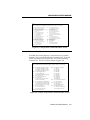
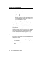
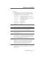
Select an Interrupt Request (IRQ)
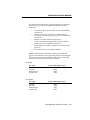
IBM-compatible computers reserve IRQ4 for COM1 and IRQ3
for COM2, as shown below. Some communication programs
support reserved IRQs for two serial ports.
Serial
Port
IRQ
Serial Port
Address (Hex)
COM1
COM2
IRQ4
IRQ3
3F8−3FF
2F8−2FF
COM3
COM4
IRQ4*
IRQ3*
3E8−3EF
2E8−2EF
*Select IRQ4 (COM3) or IRQ3 (COM4)
only after reading the following
guidelines:
If you need to use COM3 or COM4, keep the following in mind:
•
The Courier supports three additional IRQs: IRQ2,
IRQ5 and IRQ7. Your software must support the one
you use for COM3 or COM4. However, if your
computer is XT-compatible, IRQ5 is reserved for the
hard disk, and it is not available for a serial port. IRQ5
is available on 286-PCs and higher.
•
Two devices should not use the same IRQ at the same
time, because there will be a conflict and you will probably lose data. For example, if you use IRQ4 for a
mouse installed at COM1 and for your modem installed
at COM3 (as shown in the previous table) you cannot
use the mouse and the modem at the same time.
Additionally, if an installed device doesn't use IRQs,
you can use the IRQ normally associated with that
COM port. For example, if you have a serial printer at
COM1 and you know it does not use an IRQ, you can
use IRQ4 at COM3. Similarly, you could use IRQ3 at
COM4 if the device at COM2 doesn't use IRQ3.
If you cannot find the information you need in your software
documentation, call your software's Technical Support Department for help in selecting an IRQ. You may find it necessary to
re-install your serial devices to correctly allocate the available
serial ports and IRQs.
3-4
Internal Modem Set Up
COURIER HIGH SPEED MODEMS
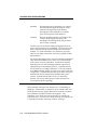
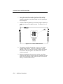
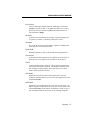
Reset the Jumpers
Figure 3.1 shows an enlarged view of the modem's jumper
switches. If you hold the modem so that the rear panel is at the
bottom and the edge connector is at the left of the circuit board
you can locate the COM and IRQ jumpers near the center left
side of the board.
Each jumper has two upright contacts connected by a black
plastic piece, called a shunt, placed over the contacts for the
COM2 and IRQ3 settings. This shunt selects the jumper by
closing the circuit.
To change a jumper setting, gently lift off the black shunt and
replace it over the contacts you want.
As we've said, your choice of an IRQ for COM3 or COM4
depends on your hardware/software configuration. If the
device at COM1 or COM2 isn't using IRQ4 or IRQ3, you may
use one of them. Otherwise, check your PC and software
documentation to see if you may use IRQ2, IRQ5 or IRQ7.
WARNING: Do not select an IRQ position until you've read
the previous guidelines and reviewed your software documentation.
Figure 3.1Jumper Switch/Serial Port Settings
Internal Modem Set Up
3-5
COURIER HIGH SPEED MODEMS
Set DIP Switches
A ten-position bank of Dual In-Line Package (DIP) switches is
located at the rear of the modem. A summary of the DIP switch
functions and options is in Appendix B in this manual and on
the Quick Reference Card.
WARNING: Check your software documentation for its
requirements, particularly for DIP switches 1, 4, 5 and 6.
NOTE: Once the modem is installed, the DIP switches are
accessible through the computer's rear panel.
INSTALLING THE MODEM
1.
Turn off the computer and peripheral devices.
2.
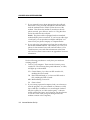
Remove the computer's cover. Refer to the computer manual, if necessary, to see which rear panel screws to remove
before sliding the cover off.
NOTE: Our illustration shows expansion slots lined up vertically on the floor of the computer. Some computers are
configured so that the expansion slots are stacked horizontally, one on top of another. The following instructions
apply for both configurations.
Figure 3.2
Removing the Computer Cover
3-6
Internal Modem Set Up
COURIER HIGH SPEED MODEMS
3.
Unscrew the solid bracket at the back of any available
standard half-card slot.)
The bracket will pop out of the back, leaving an opening in
DIP switches.
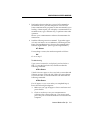
4.
and a 2-inch groove. These grooves are lined on both sides
with metal guides. Insert the modem board into the slot
modem board's edge connector firmly in the 3-inch groove.
Figure 3.3Inserting the Modem
Screw the vertical bracket at the back of the modem firmly
to the computer's rear panel, as shown in Figure 3.3. This
and keeps the modem board firmly in place.
6.
Internal Modem Set Up
3-
COURIER HIGH SPEED MODEMS
7.
If you currently have a phone plugged into the wall jack,
disconnect it. Plug one end of the phone cable that came
with the modem into the TELCO jack at the rear of the
modem. This allows the modem to switch into the telephone network, get a dial tone, and so on. Plug the other
end of the cable into the wall jack.
NOTE: The phone cable is equipped with two standard,
modular RJ11C phone connectors. If you have an older type
of wall jack, you can purchase an adapter and RJ11C connector from your phone company or computer dealer.
8.
If you wish, plug your phone's cord into the second jack on
the modem, labeled PHONE. This enables you to use your
phone for conventional voice calls, and also allows you to
switch between voice and data transmission in the same
call. See Voice/Data Communications in Appendix G for more
information.
TESTING THE INSTALLATION
Use the following procedures to verify that your modem is
working properly.
1.
Turn on your computer. Then turn the Courier's power
switch ON. The following front panel indicators, or LEDs,
will light up on the modem.
CD Carrier Detect, if you have set DIP switch 6 ON,
enabling the CD override
TR
Data Terminal Ready, if you have set DIP switch 1
ON, enabling the DTR override
MR Modem Ready/Power ON
CS
2.
3-8
Clear to Send
If you're using a personal computer, load your software to
start the program. Set your terminal or software to 19.2K
bps or 9600 bps. In addition, set a word length of either 7
bits plus 1 parity bit, or 8 bits with no parity—it doesn't
matter which at this time—and 1 Stop bit. Set the software
to use the correct serial port (port through which the
modem connects to the computer).
Internal Modem Set Up
COURIER HIGH SPEED MODEMS
3.
Perform the function that lets you send AT commands to
the modem, that is, puts the computer in Terminal mode.
Some communications programs do this automatically upon
loading. Others require you to display a communications or
terminal screen, type a Function key, or perform some other
operation.
Review your communications software documentation for
instructions.
4.
Send the following attention command. Type either upper
or lower case letters, not a combination, and then press the
Enter (Carriage Return) key, shown in the example below
between angle brackets. (Don't type the angle brackets.)
AT <Enter>
If everything is correct, the modem responds as follows:
OK
Go on to step 5.
Troubleshooting
If your entered command is not displayed, your local echo is
OFF. To turn the local echo ON, send the modem the
following command:
ATE1 <Enter>
If double characters appear on the screen, both your modem and
software are set to local echo ON. Either set your software
to local echo OFF, or turn the modem's echo OFF with the
following command:
ATE0 <Enter>
If no OK appears on your screen after you completed Step 4,
review the following checkpoints:
a.
Make sure you type all upper or lower case letters and
press <Enter>.
b. Check to see that you set your communications
software to the correct serial port. The correct serial
port is the port to which the modem is connected to the
computer.
Internal Modem Set Up
3-9
COURIER HIGH SPEED MODEMS
c.
Make sure your software has put the computer in
Terminal mode, so that you can send the modem
commands. Then review Step 4, on the previous page.
d. Be sure that DIP switches 1 and 6 are set ON or OFF
according to your terminal or software requirements.
The table in Appendix B explains each function, and
you may also need to review your terminal or
communications software documentation.
e.
If you set DIP switch 8 OFF, for Dumb mode, reset the
modem to Smart mode: set DIP switch 8 to ON.
f.
The modem is shipped with DIP switch 3 ON, enabling
the result codes. If DIP switch 3 is OFF, set it to the ON
position. Then initiate the new switch setting with the
following reset command:
ATZ <Enter>
5.
As a final check, make sure the modem gets a dial tone.
Type the following Dial command:
ATD <Enter>
On receipt of the command, the modem goes off hook and
waits for a dial tone. The OH indicator lights up, and you'll
hear the dial tone from the modem's speaker. To cancel the
operation, press any key.
Troubleshooting
If you don't hear the dial tone, first increase the volume by
using the L command. If that doesn't work, check to see
that the phone cable from the wall jack is connected to the
correct jack on the modem. If necessary, reconnect the
phone cable correctly. Then try the Dial command again,
ATD <Enter>.
3-10
Internal Modem Set Up
COURIER HIGH SPEED MODEMS
CHAPTER 4. DATA MODE OPERATIONS
The information in this chapter applies to asynchronous calls
only. For synchronous operations, refer to Appendix F.
Detailed command descriptions are in this chapter. Additional
command summaries are in Appendix C, on the bottom panel
of the modem, and in the Quick-Reference Card.
COMMAND SET USAGE
The Courier command set enables you to send the modem two
kinds of instructions:
•
operations, such as dialing or hanging up
•
configurations, such as enabling error control or data
compression
Follow these guidelines:
1.
Your software must be loaded and, if you are using a
computer, it must be in Terminal mode.
Some communications programs put the computer in
terminal mode automatically when they are loaded.
Others require you to display a communications
terminal screen, press a Function key, or perform some
other operation. Refer to your communications
software documentation for instructions.
In Terminal mode the computer acts as if it were a standard terminal such as a teletypewriter, rather than a
data processor. Keyboard entries go directly to the
modem, whether the entry is a modem command or
data to be transmitted over the phone lines. Received
data is output directly to the screen.
2.
Type commands in either upper or lower case, not a
combination (AT or at—not At).
Data Mode Operations
4-1
COURIER HIGH SPEED MODEMS
3.
All commands except A/, A> and +++ are preceded by
the AT (attention) prefix and are executed with the
Enter/Carriage Return key (<Enter>).
4.
Command length = 60 characters maximum. The
modem doesn't count the AT prefix, Carriage Return
character, or spaces. It counts (but doesn't act on)
punctuation such as hyphens and parentheses.
5.
A missing numeric parameter is assumed to be zero, as
in the command to hang up: ATH <Enter> is the
equivalent of ATH0 <Enter>.
Example (spaces are not required, but are added here for
readability):
AT &K3 X2 DT 071 312 1234 <Enter>
AT
&K3
X2
DT
<Enter>
Attention; a command follows.
Disable MNP5 data compression; use only
V.42 bis compression.
Use the X2 result code subset.
Dial the following number using tone dialing.
Execute the commands.
This chapter groups related commands into the following
categories.
• Basic Commands
• Dialing/Answering
Dialing
Dial Options
Cancel Dialing
Store Phone Numbers
Redialing
Answer Mode
Auto Answer
Hanging Up
• Setting/Using Defaults
Customizing NVRAM
Resetting the Modem
4-2
Data Mode Operations
COURIER HIGH SPEED MODEMS
•
•
•
•
•
•
Configuration:
Echo/Speaker
Result Codes
Modulation
Error Control/Data Compression
Data Rates
RS-232 Signal Operations
Flow Control
S-Registers
Inquiry and Help
Testing
International Calls
Miscellaneous Commands
For an alphabetical listing of commands, check the first page of
the index.
NOTE: The defaults listed are based on the modem's shipping
configuration: load from nonvolatile random access memory
(NVRAM), DIP switch 10 OFF, which is the same as the &F1
configuration template). For a complete listing of default
configuration templates, see Appendix B.
BASIC COMMANDS
AT
Attention command prefix. Use AT alone to test for the OK
result code. AT must prefix all commands except A/, A> and
+++.
Any
key
Terminate the current dialing operation resulting from an
issued Dial command; terminate Repeat mode (> or A>).
Data Mode Operations
4-3
COURIER HIGH SPEED MODEMS
DIALING/ANSWERING
Dialing
Dn
Dial the specified phone number; also execute Dial options.
The maximum number of characters allowed is 60, including the
AT prefix, punctuation and spaces. The Carriage Return (Enter
key) isn't counted as a character.
NOTE: With the exception of the following Dial options, the
modem ignores any commands issued after D in the same
command string.
Dial Options
D
Dial the number that follows and enter Originate mode.
Optional parameters:
P
Pulse dial. Default.
T
Tone dial.
,
(Comma) Pause for 2 seconds before continuing to dial.
;
Return to Command mode after dialing. If your phone is
plugged into the modem, you can use this option to have
the modem Auto Dial a telephone rather than a modem.
The Courier dials, remains off hook and returns the OK
message, indicating it is in Command mode.
For example, to have the modem place a voice call, enter
the Dial command with a semicolon:
ATDT5551234; <Enter>
When the modem returns the OK result, pick up your
phone receiver so you can talk to the other party, and
send the command that hangs up the modem:
ATH <Enter>
4-4
Data Mode Operations
COURIER HIGH SPEED MODEMS
"
Dial the letters that follow (in an alphabetical phone
number). NOTE: If you are including another command
after the dial string, use closing quotation marks before
the additional command.
!
Transfer a call (flash the switch-hook). This command
applies to modems in installations where other modems
share the phone line. The modem flashes the switchhook (goes off hook 0.5 seconds, on hook for 0.5 seconds
and off hook again) to dial the specified extension.
W
This command is useful in situations where you must
wait for a second dial tone before continuing dialing. For
example, if you need to dial for an outside line, the
Courier continues dialing as soon as it detects the next
dial tone.
AT DT 9 W 5551234 <Enter>
NOTE: This command executes only if result code
option X3 or greater has been issued. If the modem is set
to X2 or lower, the modem interprets the W as a comma
(two-second pause).
@
Wait for an answer (with X3 or higher). Some online
services answer the phone and return a tape-recorded
request for information before processing transactions.
In such instances, the @ command can be used in the Dial
string to tell the modem to detect at least one ring, wait
for five seconds of silence at the other end of the call, and
then continue to execute the Dial string.
To use the @ command, set the modem to X3, X4 or X7.
If the modem is set to X2 or lower, the modem returns an
ERROR message when encountering the @ character in a
command string. If set to X5 or X6, the modem hangs up
when it detects a voice answer and sends the VOICE
result code.
/
A slash (/) causes a pause of only 125 milliseconds.
Data Mode Operations
4-5
COURIER HIGH SPEED MODEMS
R
Reverse frequencies. This command allows calls to an
originate-only modem. It reverses the modem's
originate/answer frequencies, forcing the Courier to dial
out at the answer frequency. The command follows the
Dial command, before or after the phone number:
AT D1234567R <Enter>
X2-X7
Adaptive dialing. When any of the X2 through X7 options is in
effect and you do not issue a dialing type in the Dial string, the
Courier uses tone dialing, which is faster than the default pulse
type. However, if the phone company's central office does not
have tone detection equipment, the modem cannot break dial
and continues to detect the dial tone. If this occurs, the modem
automatically reverts to pulse dialing.
DL
Dial the last-dialed number. The modem stores each Dial
command until it receives the next Dial command. Use DL
instead of A/, described on the next page, if you wish to send
the modem non-Dial commands before dialing again.
DSn
Dial the number stored in nonvolatile random access memory at
position n, where n = 0−9.
Cancel Dialing
To cancel Dial-command execution, press any key. If you
inadvertently hit a key on the keyboard while the modem is
dialing, the call is canceled. If this occurs, type the A/
command explained under Automated Redialing below.
When the modem receives a command, it stores the instruction
in its command buffer until it receives the next AT command.
Note that if you've sent the modem an additional command
since the Dial command, A/ re-executes that command instead
of redialing.
4-6
Data Mode Operations
COURIER HIGH SPEED MODEMS
Store Phone Numbers
&Zn=s
This command stores up to ten numbers, where n is the position
0−9 in nonvolatile memory, and s is the phone number string.
The number-string may be up to 40 characters long, including
any Dial command options.
AT &Z2=555-6789 <Enter>
Do not include modem settings in the &Zn string. If the call
requires a special setting, insert it in the command string before
the DSn command. In the following example, &M0 (no error
control) is inserted before the Dial command:
AT&M0 DS2 <Enter>
NOTE: The &Zn=s command functions differently when Dial
Security is enabled. See Appendix D for more information.
&Zn?
Display the phone number stored in NVRAM at position n
(n = 0−9).
Redialing
A/
Re-execute the last issued command. A/ doesn't take the AT
prefix or a Carriage Return, and can be used to redial.
A/
Automated Redialing (>, A>)
While > and A> can be used to continuously repeat any
command, they are designed for automated redialing.
>
Enter Repeat Mode
If you know the modem you are calling is frequently busy,
include the Repeat command in the Dial string, as follows:
AT > DT 1234567 <Enter> or
AT DT 1234567 > <Enter>
The modem enters Repeat mode, dials the number, waits 60
seconds for a carrier (default), and hangs up. Then after a twosecond pause, it redials.
Data Mode Operations
4-7
COURIER HIGH SPEED MODEMS
The cycle continues until the modems connect or the modem
reaches a maximum of 10 attempts. The 10-try limit is
mandated by Industry Canada (IC) to prevent tying up local
telephone company exchanges with unconnected calls.
A>
This command combines the features of both the A/ and >
commands. The modem enters Repeat mode as described
above, and redials the Dial string in the command buffer. Like
the A/ command, A> does not take the AT prefix or a Carriage
Return.
Exit Repeat Mode
Should you use > or A> with a command other than a Dial
string, abort the cycle by pressing any key.
To abort automated redialing, be sure to press any key when the
result code appears, during the pause before the modem begins
dialing again. If you press any key while the modem is dialing,
that dial attempt is canceled but the cycle continues.
Answer Mode
Force Answer Mode
A
Force Answer mode when the modem hasn't received an
incoming call.
Auto Answer
The Courier is shipped with DIP switch 5 ON, Auto Answer
suppressed. To set the modem to automatically answer
incoming calls, do one of the following:
1.
Before powering on the modem, set DIP switch 5 OFF.
When you turn the computer on, the modem answers
incoming calls on the first ring.
2.
When the modem is on, set your communications
software to enable auto answer. The following command
instructs the modem to answer on the first ring. (You can
substitute a higher value. See the S-Register summary in
Appendix B.)
AT S0 = 1 <Enter>
4-8
Data Mode Operations
COURIER HIGH SPEED MODEMS
When the modem senses a call coming in, it sends the result
code RING to your screen, goes off hook, and sends the remote
modem a high-pitched answer tone. If there is no Carrier
Detect within 60 seconds, the modem hangs up. If the
connection is made, the modem sends a CONNECT result code.
When the call is disconnected by you or the remote user, the
modem hangs up and returns the NO CARRIER code.
NOTE: If DIP switch 5 is OFF and S0=0, the Auto Answer will
be disabled. Be sure that S0=1−256.
Suppressing Auto Answer
To disable Auto Answer, reverse Steps 1 or 2 above. Set DIP
switch 5 ON before powering on the modem, or set the modem
to answer on zero rings with the following command.
AT S0 = 0 <Enter>
Points to Remember
1.
If the modem is attached to a computer, you can set the
modem to receive calls when you're not at your computer.
Load your communications software as you normally do,
and set the modem to Auto Answer. Also set your
software's host mode function to save incoming messages
and/or files.
2.
If you've attached your phone so it can be used for conventional calls, disable Auto Answer when you are not
expecting incoming data calls. Otherwise, your modem
may answer the phone before you do, greeting a voice caller
with a high-pitched answer tone.
Hanging Up
Hn
On/off hook control.
H0
Hang up (go on hook).
H1
Go off hook.
Data Mode Operations
4-9
COURIER HIGH SPEED MODEMS
+++
Escape code operations. Once the modem is online to another
system, the only command it recognizes is an escape code of three
typed pluses, which forces the modem back to Command mode.
Do the following when issuing the command:
•
Wait one second after sending the last item of data
•
Type: +++
•
Wait one second before typing any data
Do not type the AT prefix or a Carriage Return. The guard time
of one second before and after the code prevents the modem
from misinterpreting the occurrence of +++ in the transmitted
data stream.
If necessary, the character used in the escape code or the duration of the guard time can be changed by resetting Register S2
or S12. See the S-Register Summary in Appendix B.
In response to +++, the modem returns to Command mode.
However, it keeps the line open or hangs up, depending on the
setting of DIP switch 9:
DIP Switch 9 Response to +++
OFF
Modem goes on hook (hangs up), sends NO
CARRIER result code (factory setting)
ON
Modem maintains connection (Online-Command
mode), sends OK result code
The factory setting (OFF) forces an automatic disconnect when
you issue +++. One advantage of this is that you are not likely
to inadvertently run up an all-night phone bill.
Set DIP switch 9 ON if you want the modem to respond to +++
by entering Online-Command mode, enabling it to execute
commands and return online. (See the O command, next.)
WARNING: For unattended modem operations: in rare instances,
the modem may fail to recognize the +++ escape code sequence.
If you are running the modem under software control for
unattended operations, we suggest you use the sure fire method
of dropping the DTR signal from the computer or terminal for
at least 50 milliseconds, to avoid costly phone charges.
Methods of turning the DTR signal offfor example, closing the
communications portdiffer from one computer to another.
4-10
Data Mode Operations
COURIER HIGH SPEED MODEMS
Returning Online
On
If DIP switch 9 is ON (on detection of the escape code the
modem maintains the connection), you can issue commands
and then toggle the modem back online with the On command,
as in this example:
AT Q1 O <Enter>
There are two ways to return online.
ATO0 Return online (normal). (Used in the example above.)
ATO1 Return online and retrain. Use to have the modem resynchronize if there were errors in a non-ARQ data
transfer.
Hanging Up
If DIP switch 9 is ON, the escape code forces the modem back to
Command mode but leaves the line open. If you want the
modem to hang up, issue the following command once the
modem sends the OK result code:
ATH <Enter>
If DIP switch 9 is OFF, the modem automatically hangs up on
receipt of the escape code.
SETTING/USING DEFAULTS
The modem's read-only memory (ROM) permanently stores the
modem's four factory template settings. Nonvolatile random
access memory (NVRAM) allows you to save one of these four
templates, or add your own modifications, and write all the
settings to NVRAM as your power-on defaults.
&Fn
The modem is shipped with four configurations (templates),
&F0−&F3, stored in permanent nonprogrammable memory
(ROM). Appendix B includes configuration listings for each
template. Any one of the templates may be loaded into current
memory (AT &Fn) or written to nonvolatile memory to serve as
the reset default (AT &Fn &W). Note, however, that &F0 is
always loaded into memory if DIP switch 10 is ON.
Data Mode Operations
4-11
COURIER HIGH SPEED MODEMS
When you power on the Courier, it loads the settings stored in
NVRAM if DIP switch 10 is OFF. Until you write your own
settings to NVRAM, the defaults stored there are the same as
the permanent ROM factory settings stored in position 1, &F1.
To view the &F1 settings, select option 5 of the I (inquiry)
command:
AT I5 <Enter>
Customizing NVRAM
&W
To substitute a template other than &F1, write the desired
template to NVRAM, using the &W command.
AT &F2 &W <Enter>
To modify the &Fn configuration in NVRAM, type your
changes and then save them to NVRAM, as in the following
example. The original factory template remains intact.
AT M2 S10=40 &A2 &W <Enter>
NOTE: When writing a different default configuration to
NVRAM, insert any additions after the &Fn command but before
&W. Otherwise they will be overwritten by &Fn.
After sending a configuration to NVRAM, you can change any
setting just for the current session, as in the following example.
The NVRAM configuration remains intact.
ATX6 <Enter>
But if you want the new setting to be a default, write it to
NVRAM at the same time, as in the following example. X7 is
substituted for the Xn value stored earlier. Any other setting
that was changed and can be saved to NVRAM will also be
saved.
AT X7 &W <Enter>
4-12
Data Mode Operations
COURIER HIGH SPEED MODEMS
Resetting the Modem
Z
Software reset to NVRAM settings when DIP switch 10 is OFF
(factory setting). If DIP switch 10 is OFF, the modem resets to
the &F0 configuration template, with no flow control.
NOTE: Use the ATZ command also if you've changed the
position of DIP switches 1−7 or 9 while the modem is on, so that
the modem can read the new setting. The only other way to
initiate a new setting for switches 1−7 and 9 is to turn the
modem off and on again.
CONFIGURATION
Echo/Speaker
En
Command mode local echo. Enables/disables the display of
your typed commands. If double characters appear on the
screen, both the modem's local echo and your software's local
echo are on.
The Courier is shipped with DIP switch 4 OFF, enabling local
echo. The En command controls the local echo for a current
session, independently of the switch setting. At power-on and
reset, the modem operates according to the DIP switch setting.
The En command is not stored in nonvolatile memory as a
power-on/reset default.
Fn
E0
Command mode echo OFF. The modem does not
display keyboard commands.
E1
Command mode echo ON.
Online local echo. This command causes the modem to display
a copy of the data it is transmitting to another system. Many
systems, however, return a copy of received data, which is
called a remote echo. If the modem's online echo is ON and
there is also remote echoing, double characters appear on the
screen.
Data Mode Operations
4-13
COURIER HIGH SPEED MODEMS
In some microcomputer documentation, the term duplex is
applied to local online echoing, although the term is not technically accurate.
Mn
F0
Online echo ON. Sometimes called half duplex. As the
modem transmits data to a remote system, it also sends a
copy of the data to the screen.
F1
Online echo OFF. Sometimes called full duplex. Default.
Speaker (audio monitor).
M0
The speaker is always OFF.
M1
The speaker is ON until carrier is established. Default.
M2
The speaker is always ON, including during data
transfer.
M3
The speaker is ON after the last digit is dialed and
remains ON until carrier is established.
Result Codes
Qn
Enable/suppress the display of result codes. The Courier is
shipped with DIP switch 3 ON, to display result codes. Use the
Qn command to control the display for a current session,
independently of the switch setting.
At power-on and reset, the modem operates according to the
DIP switch setting. The Qn command is not stored in nonvolatile random access memory.
Vn
4-14
Q0
Result codes displayed.
Q1
Result codes suppressed (quiet).
Q2
Result codes suppressed in Answer mode.
Return result codes in words or numbers (Verbal/Numeric
mode). At power-on and reset, the modem operates according
to the DIP switch setting. The Vn command is not stored in
nonvolatile memory as a power-on/reset default.
V0
Numeric mode.
V1
Verbal mode.
Data Mode Operations
COURIER HIGH SPEED MODEMS
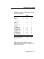
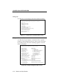
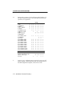
Xn
Result code set options. Use the following table (Default = X7,
all codes except 12/VOICE). For result codes for synchronous
operations, see Appendix F.
Result Codes
0/OK
1/CONNECT
2/RING
3/NO CARRIER
4/ERROR
X0
•
•
•
•
•
Setting
X3 X4
•
•
•
•
•
•
•
•
•
•
X1
•
•
•
•
•
X2
•
•
•
•
•
X5
•
•
•
•
•
X6
•
•
•
•
•
X7
•
•
•
•
•
5/CONNECT 1200
6/NO DIAL TONE
7/BUSY
8/NO ANSWER
9/RESERVED
•
•
•
•
•
•
•
•
•
•
•
•
•
•
•
•
•
•
•
•
•
10/CONNECT 2400
11/RINGING
12/VOICE
13/CONNECT 9600
18/CONNECT 4800
20/CONNECT 7200
21/CONNECT 12000
25/CONNECT 14400
47/CONNECT 16800
85/CONNECT 19200
91/CONNECT 21600
99/CONNECT 24000
103/CONNECT 26400
107/CONNECT 28800
•
•
•
•
•
•
•
•
•
•
•
•
•
•
•
•
•
•
•
•
•
•
•
•
•
•
•
•
•
•
•
•
•
•
•
•
•
•
•
•
•
•
•
•
•
•
•
•
•
•
•
•
•
•
•
•
•
•
•
•
•
•
•
•
•
•
•
•
•
•
•
•
•
•
•
•
•
•
•
•
•
•
•
•
•
•
•
•
•
•
•
•
•
•
•
•
•
•
•
•
•
•
•
•
•
•
•
•
Functions
Adaptive Dialing
Wait for 2nd Dial Tone (W)
Wait for Answer (@)
Fast Dial
•
Table 4.1
Result Code Options
NOTE: Additional messages indicate an error control
connection and the modulation for a call. See the next section,
Additional Result Code Subsets.
Data Mode Operations
4-15
COURIER HIGH SPEED MODEMS
Result Code
0/OK
1/CONNECT
2/RING
3/NO CARRIER
4/ERROR
5/CONNECT 1200
6/NO DIAL TONE
7/BUSY
8/NO ANSWER
10/CONNECT 2400
11/RINGING
12/VOICE
13/CONNECT 9600
Adaptive Dialing
Wait for Another
Dial Tone (W)
Wait for an
Answer (@)
Fast Dial
Meaning
Command has been executed.
Connection with another modem; if set to X0, connection
may be between 300 and 28.8 bps; if X1 or higher,
connection is at 300 bps.
Incoming ring detected.
Carrier detect has failed or carrier has been dropped due to
disconnect.
Command is invalid.
Connection with another modem at 1200 bps.
Dial tone not detected during the normal 2 seconds, set in
Register S6.
Busy signal detect; modem hangs up.
After waiting 5 seconds for an answer, modem hangs up;
returned instead of NO CARRIER when the @ option is
used.
Connection with another modem at 2400 bps.
The modem has dialed; remote phone line is ringing.
Voice answer at remote site; modem hangs up.
Connection at reported rate. Same meaning for results of
4800 (18), 7200 (20), 12K (21), 14.4K (25), 16.8K (43), 19.2K
(85), 21.6K (91), 24K (99), 26.4K (103), or 28.8K (107)
The modem attempts to use tone dialing and, if that
doesn't work, reverts to rotary dialing.
The modem continues dialing as soon as it detects
another dial tone. See the dial options earlier in this
chapter.
The modem continues dialing when it detects 5 seconds of
silence on the line. See the dial options earlier in this
chapter.
The modem dials immediately on dial-tone detect, instead
of waiting the normal 2 seconds set in Register S6.
Table 4.2
Result Code Definitions
4-16
Data Mode Operations
COURIER HIGH SPEED MODEMS
Additional Result Code Subsets
NOTE: ARQ (Automatic Repeat Request) is used in this
manual to denote calls under error control.
&An
Enable/disable additional result code subsets. See the Xn
command earlier in this chapter.
&A0 ARQ result codes are disabled. This setting does not
affect an error control connection; the modem returns the
standard CONNECT messages if result codes are
enabled.
&A1 ARQ result codes are enabled, indicating that a
connection is under error control. Message 14 is
displayed if the modem is set to X0 and the connection is
at any rate from 1200 to 28.8K bps. The remaining results
indicate the connection rate and require a setting of X1 or
higher.
14/CONNECT/ARQ
15/CONNECT 1200/ARQ
16/CONNECT 2400/ARQ
17/CONNECT 9600/ARQ
19/CONNECT 4800/ARQ
22/CONNECT 12000/ARQ
24/CONNECT 7200/ARQ
26/CONNECT 14400/ARQ
57/CONNECT 16800/ARQ
88/CONNECT 19200/ARQ
94/CONNECT 21600/ARQ
100/CONNECT 24000/ARQ
104/CONNECT 26400/ARQ
108/CONNECT 28800/ARQ
&A2 Additional VFC, V34, HST, or V32 modulation indicator.
Included for users of HST Dual Standard modems. If
your software cannot handle the added modulation
information, select &A1 or &A0.
23/CONNECT 9600/HST
28/CONNECT 4800/HST
30/CONNECT 7200/HST
31/CONNECT 12000/HST
35/CONNECT 14400/HST
53/CONNECT 16800/HST
33/CONNECT 9600/V32
38/CONNECT 4800/V32
40/CONNECT 7200/V32
41/CONNECT 12000/V32
45/CONNECT 14400/V32
83/CONNECT 16800/V32
87/CONNECT 19200/V32
27/CONNECT 9600/ARQ/HST
29/CONNECT 4800/ARQ/HST
34/CONNECT 7200/ARQ/HST
32/CONNECT 12000/ARQ/HST
36/CONNECT 14400/ARQ/HST
57/CONNECT 16800/ARQ/HST
37/CONNECT 9600/ARQ/V32
39/CONNECT 4800/ARQ/V32
44/CONNECT 7200/ARQ/V32
42/CONNECT 12000/ARQ/V32
46/CONNECT 14400/ARQ/V32
84/CONNECT 16800/ARQ/V32
90/CONNECT 19200/ARQ/V32
Data Mode Operations
4-17
COURIER HIGH SPEED MODEMS
93/CONNECT 21600/V32
97/CONNECT 21600/VFC
101/CONNECT 24000/VFC
105/CONNECT 26400/VFC
109/CONNECT 28800/VFC
139/CONNECT 14400/VFC
143/CONNECT 16800/VFC
147/CONNECT 19200/VFC
111/CONNECT 21600/V34
113/CONNECT 24000/V34
115/CONNECT 26400/V34
117/CONNECT 28800/V34
120/CONNECT 2400/V34
124/CONNECT 4800/V34
128/CONNECT 7200/V34
132/CONNECT 9600/V34
136/CONNECT 12000/V34
140/CONNECT 14400/V34
144/CONNECT 16800/V34
148/CONNECT 19200/V34
96/CONNECT 21600/ARQ/V32
98/CONNECT 21600/ARQ/VFC
102/CONNECT 24000/ARQ/VFC
106/CONNECT 26400/ARQ/VFC
110/CONNECT 28800/ARQ/VFC
141/CONNECT 14400/ARQ/VFC
145/CONNECT 16800/ARQ/VFC
149/CONNECT 19200/ARQ/VFC
112/CONNECT 21600/ARQ/V34
114/CONNECT 24000/ARQ/V34
116/CONNECT 26400/ARQ/V34
118/CONNECT 28800/ARQ/V34
122/CONNECT 2400/ARQ/V34
126/CONNECT 4800/ARQ/V34
130/CONNECT 7200/ARQ/V34
134/CONNECT 9600/ARQ/V34
138/CONNECT 12000/ARQ/V34
142/CONNECT 14400/ARQ/V34
146/CONNECT 16800/ARQ/V34
150/CONNECT 19200/ARQ/V34
&A3 Additional error control indicator (LAPM, HST, MNP,
SYNC, or NONE) and data compression type (V42BIS or
MNP5). Default. When the call is not under one of those
protocols (and ARQ is not included in the result code),
the modem reports either SYNC, indicating a synchronous connection, or NONE, for no protocol.
If the modems are using data compression, the type of
compression, V42BIS or MNP5, is added to the result
code. In the first of the following examples, the modems
negotiated error control for the call (ARQ), used VFC
modulation, are using the LAPM error control protocol,
and are using V.42 bis compression.
CONNECT 28800/ARQ/VFC/LAPM/V42BIS [or MNP/MNP5]
CONNECT 19200/ARQ/V32/LAPM/V42BIS [or MNP/MNP5]
CONNECT 16800/ARQ/HST/HST/V42BIS [or MNP/MNP5]
CONNECT 14400/ARQ/V32/LAPM/V42BIS [or MNP/MNP5]
CONNECT 9600/ARQ/HST/CELLULAR/HST/V42BIS [or MNP5]
CONNECT 9600/SYNC
CONNECT 2400/NONE
NOTE: Although these codes will return numeric identifiers,
they are the same numeric identifiers used for &A2 result codes.
If the modem is in Numeric mode (V0) and set to &A3, you will
not be able to differentiate between &A2 and &A3 result codes.
&A3 result codes may not be compatible with some software.
4-18
Data Mode Operations
COURIER HIGH SPEED MODEMS
Modulation
Bn
Handshake options. There are three commands that apply to
international calls above 1200 bpsBn, &Gn, &Pn. See
International Calls later in this chapter for information on the
other two settings.
B0
ITU-T (formerly CCITT) answer sequence. Default. This
is required to answer all V.32-type calls, as well as calls
from overseas.
B1
Bell answer tone. This setting selects HST modulation in
Dual Standard modems, but should only be used if the
modem is not required to answer V.32-type calls.
NOTE: This setting is required for HST cellular calls.
Error Control/Data Compression
&Mn
Enable ARQ (error control) or synchronous protocols. Both
your modem and the remote modem must use the same
protocol.
&M0 Normal mode, no error control. Due to the nature of
phone line channels, this is never recommended for calls
above 2400 bps.
&M1 This setting is exclusive of the modems' error control and
is used only for online synchronous mode without V.25
bis. See Appendix F for more information .
&M2 Reserved.
&M3 Reserved.
&M4 Normal/ARQ mode. Default. If an ARQ connection isn't
made, the modem operates in Normal mode, as though it
were set to &M0.
NOTE: When V.32-type modems revert to Normal
mode, they transfer data at high speeds without the
reliability of error control. To avoid this, both local and
remote modems should always be set for error control.
Modems in HST mode, if unable to establish an error
control connection, drop to 2400 bps.
&M5 The modem enters ARQ asynchronous mode. The
modem hangs up if an ARQ connection cannot be made.
Data Mode Operations
4-19
COURIER HIGH SPEED MODEMS
&M6 The modem enters V.25 bis synchronous mode, using a
character-oriented link protocol similar to BISYNC. See
Appendix F for more information
&M7 The modem enters V.25 bis synchronous mode, using the
HDLC link protocol.
&Kn
Enable/disable data compression.
&K0 Data compression disabled.
&K1 Auto enable/disable. Default. The modem enables
compression if the serial port rate is fixed, &B1. It
disables compression if the serial port rate follows the
connection rate, &B0, because compression offers no
throughput advantage when the serial port and
connection rates are equal. Compression may even
degrade throughput.
&K2 Data compression enabled. Use this setting to keep the
modem from disabling compression.
&K3 Selective data compression. The modem negotiates only
for V.42 bis compression, and disables MNP Level 5
(MNP5) compression. Use this setting to transfer 8-bit
binary files, .ZIP files, and other files that are already
compressed. See the note below.
NOTE: MNP5 compression is not useful when transferring files
that are already compressed, such as the .ZIP files downloaded
from many Bulletin Boards and 8-bit binary files, which appear
to the modem to be compressed. MNP5 tends to add data to
the transmission so that throughput over the link degrades.
V.42 bis compression dynamically detects when data is already
compressed and turns off until it detects that compression will
work to advantage. The special &K3 setting enables the best
throughput for already-compressed files.
See Throughput Guidelines and Data Compression in Appendix A
for more information, including throughput to expect for different kinds of files.
4-20
Data Mode Operations
COURIER HIGH SPEED MODEMS
Data Rates
The modem can be set to a fixed or variable serial port rate. A
fixed rate sets the modem for the highest possible throughput
and provides the best performance. A variable rate allows the
modem to switch to match the more limited rate on the phone
connection.
Your software must support fixed or variable serial port rates,
and must be set to either of the two settings. NOTE: Your
software may refer to these options with terms like locked serial
port (fixed rate) or autobaud (variable rate).
Most communications programs support variable rates, but not
all software supports fixed rates.
WARNING: To connect above 9600 bps, the serial port rate
must be 19.2K, 38.4K, 57.6K, or 115.2K bps. If the local
computer is limited to 9600 bps, V.32 terbo modems are limited
to 9600 bps maximum, that is, V.32. Disable V.32 terbo
modulation so that the modem does not switch its serial port
rate up higher than 9600 bps. Do this by setting Register S34 to
3 (S34=3) and including that setting in the defaults you write to
nonvolatile memory, as shown in Setting/Using Defaults earlier
in this chapter.
&Bn
Serial port rate variable or fixed.
&B0
Variable rates. When the modem switches its connection
rate to connect with a modem operating at a different
rate, it also switches its serial port rate. The software or
terminal also switches serial port rates to match the
connection rate.
&B1
Fixed rate. Default. The modem always communicates
with the terminal or computer at the rate at which you
have set the terminal or software, regardless of the
connection rate. For the greatest throughput, set the
serial port to 115.2K, 57.6K, 38.4K bps for high speed
calls and to at least 9600 bps for 2400-bps calls.
This setting is not affected by the &N setting. However,
the serial port rate must be equal to or higher than the &Nn
rate.
Data Mode Operations
4-21
COURIER HIGH SPEED MODEMS
&B2
Fixed for ARQ calls/Variable for non-ARQ calls. Answer
mode only. When the modem goes off hook and
connects in ARQ mode, it shifts its serial port rate up to a
user-specified rate, for example, 38.4K bps. If the
connection is not under error control, the modem
behaves as if it were set to &B0 and switches its serial
port rate to match the connection rate of each call.
To implement this feature, first set your software to the
desired rate. Then send the modem the AT &B2 [other
settings] &W command.
The modem stores the rate of the command in NVRAM
along with the settings. Each time it makes an ARQ
connection, the modem checks NVRAM for the specified
serial port rate.
When sending subsequent configurations to NVRAM, be
sure your software is set to your selected serial port rate,
so that the correct rate is maintained.
&Nn
Connection rate variable or fixed.
&N0 Variable rates. Default. The Courier negotiates with the
remote modem for the highest possible connection rate,
depending on the capabilities of the remote modem. This
is the recommended setting, and is required for the
Courier V.32 terbo to connect at 21.6K bps. Both modems
must be U.S. Robotics modems with V.32 terbo to make a
21.6K bps connection.
&N1- Fixed rate. The modem only connects if the remote
&N14 modem is operating at the same rate. If not, the modem
hangs up. If you wish, you can filter out calls at other
than a specific rate, for security or other reasons, by
fixing the connection rate.
The connection rate must always be lower than, or equal
to, the serial port rate, never higher.
4-22
Data Mode Operations
COURIER HIGH SPEED MODEMS
The options are as follows.
&N1
&N2
&N3
&N4
&N5
&N6
&N7
&N8
300 bps
1200 bps
2400 bps
4800 bps
7200 bps
9600 bps
12K bps
14.4K bps
&N9
&N10
&N11
&N12
&N13
&N14
16.8K bps (HST, terbo,
V.FC, and V.34 only)
19.2K bps (terbo, V.FC,
and V.34 only)
21.6K bps (terbo, V.FC,
and V.34 only)
24K bps (V.FC and V.34 only)
26.4K bps (V.FC and V.34 only)
28.8K bps (V.FC and V.34 only)
RS-232 Signal Operations
&Cn
Carrier Detect operations. At power-on and reset, the modem
operates according to the setting of DIP switch 6. This
command is not stored in nonvolatile memory as a poweron/reset default.
&C0 CD override, CD always ON.
&C1 Normal CD operations. The Courier sends a CD signal
when it connects with another modem and drops the CD
when it disconnects.
&Dn
Data Terminal Ready (DTR) operations. At power-on and reset,
the modem operates according to the setting of DIP switch 1.
This command is not stored in nonvolatile memory as a poweron/reset default.
&D0 DTR override. The modem operates as though the DTR
is always ON.
&D1 Advance usage: If issued before connecting with another
modem, the modem can enter online command mode
during a call by toggling DTR. (Most communications
software packages have a method for toggling DTR.)
&D1 functions similarly to the escape code (+++), except
that this setting is independent of DIP switch 9.
If DIP Switch 1 is ON (DTR override) when you issue the
&D1 command, the DTR override is automatically turned
off. However, if you change the setting of DIP switch 1
after issuing &D1, the DIP switch setting takes
precedence.
Data Mode Operations
4-23
COURIER HIGH SPEED MODEMS
Return online with the On command, or hang up with the
Hn command.
&D2 Normal DTR operations. The terminal or computer must
send a DTR signal for the modem to accept commands.
Dropping DTR terminates a call.
&Sn
The modem sends the computer or terminal a Data Set Ready
(DSR) signal via the RS-232 interface. (Data Set is industry
jargon for modem.) Few, if any, commercial communications
programs require the modem to control DSR, &S1. Leave the
modem set for DSR overridden, &S0, unless you know that
your installation requires a different setting.
&S0
DSR is always ON (override). Default.
&S1
In Originate mode, the modem sends the DSR after it
dials, when it detects the remote modem's answer tone.
In Answer mode, the modem sends the DSR after it
sends an answer tone.
&S2
This option is for specialized equipment such as
automatic callback units. On loss of carrier, the modem
sends a pulsed DSR signal with Clear to Send (CTS)
following Carrier Detect (CD).
&S3
This is the same as &S2, but without the CTS following
CD.
&S4
The modem sends the computer a DSR signal at the same
time that it sends the Carrier Detect (CD) signal.
Flow Control
Flow control allows the modem to monitor the amount of data
coming from the computer or the remote modem, and notify
either end if its buffers are too full, so that they stop sending
data for a moment.
The modem uses either hardware or software flow control.
Your software and machine must support whichever type you
select.
4-24
Data Mode Operations
COURIER HIGH SPEED MODEMS
Hardware Control
The modem drops the Clear to Send (CTS) signal it's been
sending to the computer or terminal when the modem's buffer
nears 90% capacity. It starts sending CTS again when the buffer
is about half full.
Software Control
The modem sends the computer or terminal the standard ASCII
Transmit OFF (XOFF) character, <Ctrl>-S, when its buffer nears
90% capacity. The modem sends the ASCII Transmit ON
character, <Ctrl>-Q, when the buffer is about half full. ASCII
definitions are as follows:
XON
XOFF
<Ctrl>-Q
<Ctrl>-S
(ASCII 17 Decimal, 11 Hex)
(ASCII 19 Decimal, 13 Hex)
NOTE: You should set your software as well to either
hardware or software flow control. Some programs also require
that you turn off the type you are not using.
The ASCII characters may be user-defined. See Registers S22
and S23 in Appendix B. That appendix also includes an ASCII
chart.
WARNING: If possible, always use hardware flow control, the
factory default. You may lose data if XON/XOFF (<Ctrl>-S,
<Ctrl>-Q) characters occur in the data stream from other
sources. They may, for example, come from the remote system:
an XON from the remote system, after your modem has sent an
XOFF, can result in buffer overflow.
<Ctrl>-S (XOFF) and <Ctrl>-Q (XON) characters also occur in
binary files, and are used by Xmodem-type protocols. You risk
having these characters misinterpreted as modem flow control
characters and dropped from the data stream.
If you cannot use hardware flow control and if you're
transferring non-text (binary) files, or using an Xmodem-type
protocol, disable flow control entirely (&H0). In addition, be
sure the modem is set to &B0 and &N0, so that the serial port
and connection rates are equal.
Data Mode Operations
4-25
COURIER HIGH SPEED MODEMS
Transmit Data Buffer Sizes
The Transmit Data refers to the data from the computer, which
the modem is to transmit over the phone line.
The size of the Transmit data buffer depends on whether the
connection is under error control or not, as follows.
•
ARQ connections: 3.25K bytes.
•
Non-ARQ connections: 1.5K bytes, allowing use of
error control file transfer protocols such as Xmodem
and Ymodem without flow control.
If bit 3 of Register S15 is turned on, the non-ARQ buffer size is
reduced to 128 bytes, for the convenience of BBS operators
taking calls from remote users of slower modems. See S-Register
Summary, S15, in Appendix B.
Received Data Buffer Size
Received Data refers to the data the modem receives over the
phone link, which the modem passes on to the attached
computer.
The size of this buffer remains constant at 2K bytes.
Transmit Data Flow Control
&Hn
This type of flow control is for data transmitted to the modem
by its attached computer or terminal. The modem monitors its
buffer as data comes from the computer or modem. If the
buffer approaches 90% capacity, the modem signals the
computer or terminal to stop transmitting. When the modem
has sent enough data over the link to half empty the buffer, it
signals the computer or terminal to resume transmitting.
&H0 Transmit Data flow control disabled.
&H1 Hardware flow control. Default. Requires that your
computer or terminal and software support Clear to Send
(CTS) at the RS-232 interface.
&H2 Software flow control. Requires that your software
support XON/XOFF signaling.
4-26
Data Mode Operations
COURIER HIGH SPEED MODEMS
&H3 Use both hardware and software flow control. If you are
unsure about what your equipment supports, select this
option. But keep the warning, above, in mind about
software flow control.
Received Data Flow Control
Separate commands, &Rn (hardware) and &In (software), control the flow of Received Data passed by the Courier to your
computer or terminal.
Your software and machine must support whichever type you
select, although we recommend hardware flow control, if
possible.
Hardware Control(&Rn)
&R0 Delay Clear to Send Response after Request to Send
signal (RTS/CTS delay). The delay is required by some
synchronous mainframes and does not apply to
asynchronous calls.
&R1
The modem ignores RTS. This setting is required if your
computer or terminal or software does not support RTS.
&R2
Hardware flow control of received data enabled.
Default. The modem sends data to the computer or
terminal only on receipt of the RTS signal.
Software Control (&In)
WARNING: In ordinary operation, the only characters the
modem recognizes during a call are the three pluses (+++) of the
escape code. But when software flow control is enabled, the
modem also looks for <Ctrl>-S or <Ctrl>-Q characters. If these
characters occur in a file or as part of a protocol, the modem
reads them as XON/XOFF characters and acts on them. In
some cases, the modem drops them from the data stream.
&I0
Disables XON/XOFF flow control of received data.
Default. Recommended for non-ARQ (Normal mode)
calls, but see &I5. The I0 option provides transparency
for all characters except the escape code sequence (+++),
because at this setting the modem does not look for
control characters.
Data Mode Operations
4-27
COURIER HIGH SPEED MODEMS
NOTE: Because of the risk described in the above
warning, the settings that follow are only recommended
for users whose data does not include XON/XOFF
control characters.
&I1
The Courier acts on your typed XON/XOFF commands,
<Ctrl>-S or <Ctrl>-Q, and passes them to the remote
computer. Use in ARQ mode only, but keep in mind that
the XON/XOFF characters sent to the remote computer
may interfere with XON/XOFF signaling between the
remote computer and remote modem. See &I2.
&I2
The Courier acts on your XON/XOFF commands, but
removes them from the data stream instead of passing
them to the remote computer. This ensures that the
remote computer does not confuse your XON/XOFF
characters with those from its attached modem. This is
the recommended setting for ARQ mode.
However, if the call is not in ARQ mode, there is no flow
control on the phone link. If you send an XOFF to your
modem and it stops passing data, it has no way to tell the
remote computer and modem to stop sending for a
while, and your modem's buffer may overflow. For more
reliable control in non-ARQ mode, see &I5.
&I3
Hewlett PackardHost mode. Applies only to modems
attached to an HP mainframe that uses the ENQ/ACK
protocol. Use in ARQ mode only. See Appendix G.
&I4
Hewlett PackardTerminal mode. Applies only to
modems attached to terminals in an HP system that uses
the ENQ/ACK protocol. Use in ARQ mode only. See
Appendix G.
&I5
This setting is designed to enable flow control on the
phone link when the connection is not under error
control. For this to work for you, the remote modem
must also have &I5 capability.
In ARQ mode, a Courier set to &I5 operates the same as
it does when set to &I2. It acts on your XON/XOFF commands, but does not pass them to the remote system.
The error control protocol enables the modems to control
the flow of data on the phone link.
4-28
Data Mode Operations
COURIER HIGH SPEED MODEMS
In non-ARQ mode, a Courier set to &I5 operates as
though flow control were disabled (&I0); it does not look
for your typed XON/XOFF commands. However, it
looks for XON/XOFF characters coming in over the phone
link. When the remote operator sends XON/XOFF commands, the Courier either resumes or stops transmitting
data over the link and drops the characters from the data
stream.
If both modems are set to &I5, operators at each end can
signal the remote modem to stop sending, thereby
controlling the data flow on the phone link and
preventing their own modem's buffer from overflowing.
At the computer or terminal/modem interfaces, the
modems independently control the flow of data through
their Transmit Data (&H) settings.
Guidelines
Use of software flow control may prove satisfactory if you're
only transferring text files. However, if you're transferring nontext (binary) files, or using an Xmodem-type protocol, disable
flow control entirely (&R1, &I0). In addition, set the modem to
&B0 and &N0, so that the serial port and connection rates are
equal.
S-REGISTERS
The S-Registers are used to set various timing parameters,
redefine selected ASCII characters, and other configuration
options. A detailed summary of the S-register functions is in
Appendix B. A less detailed summary is in the Quick-Reference
card.
Sr=n
Set S-Register value: r is any S-Register; n must be a decimal
number between 0 and 255.
Sr.b=n
Alternative command for setting bit-mapped registers: r is the
bit-mapped register; .b is the bit; n is 0 (off) or 1 (on).
Sr?
Query contents of register r.
Data Mode Operations
4-29
COURIER HIGH SPEED MODEMS
INQUIRY AND HELP
The modem displays information such as the current modem
settings, product code, and call duration. It also displays
summary information for every command that the modem
supports.
For more information on Inquiry and Help commands,
including sample displays, see Chapter 6.
TESTING
The modem can perform a number of tests including Analog
Loopback, Digital Loopback, and Remote Digital Loopback.
These tests can be used to check the operations of the modem's
transmitter and receiver, or to locate a problem with a remote
modem or telephone channel. Error control must be disabled
for these tests.
See Appendix H for more information.
INTERNATIONAL CALLS
There are three commands that apply to international calls
above 1200 bpsBn, &Gn, &Pn. Bn is described earlier in this
chapter.
&Gn
This setting applies only to overseas calls at 2400 or 1200 bps.
British phone switching systems require the modem to send an
1800 Hz guard tone after it sends an answer tone. Some other
European phone networks require a 550 Hz guard tone. Guard
tones are not used in the United States or Canada.
&G0 No guard tone. This is used in the U.S. and in Canada.
Default.
&G1 This sets a 550 Hz guard tone, and is used in some
European countries.
&G2 This sets an 1800 Hz guard tone, and is used in the U.K.
and some Commonwealth countries. &G2 requires the
B0 setting.
4-30
Data Mode Operations
COURIER HIGH SPEED MODEMS
&Pn
This command sets the ratio of the off-hook/on-hook (make/
break) interval for pulse dialing. The default sets the modem
for use in North America. The ratio must be changed if the
modem is used in the United Kingdom and some Commonwealth countries.
&P0
Make/break ratio, U.S./Canada: 39%/61%. Default.
&P1
Make/break ratio, United Kingdom, some
Commonwealth countries: 33%/67%.
MISCELLANEOUS COMMANDS
Cn
Kn
&Yn
Transmitter enabled/disabled.
C0
Transmitter disabled; receive-only condition.
C1
Transmitter enabled. Default.
Modem clock operation: Call-duration or Real-time mode.
Displayed with ATI3 and ATI6 commands.
K0
Display current call-duration if online. Display
last call-duration if offline. Default.
K1
Return actual time at ATI3. Clock is set using
ATI3=HH:MM:SS K1.
Break handling. This command allows you to send a break to
abort data transfer without disconnecting from the phone link.
&Y0
Destructive, don't send Break.
&Y1
Destructive, expedited (Default).
&Y2
Nondestructive, expedited.
&Y3
Nondestructive, unexpedited; modem sends Break in
sequence with data received from computer or terminal.
NOTE: If the call is under MNP5 data compression, destructive
Breaks cause both modems to reset their data compression
tables. When transmission resumes, the modems build new
tables, and the result is lower than normal throughput.
Data Mode Operations
4-31
COURIER HIGH SPEED MODEMS
&ZC=s
Write the following command string s to NVRAM. The
command string may be up to 30 characters long; spaces are not
counted. This command can be used so that you can call
another modem without loading your communications
software.
After storing a command, you can program the voice/data
switch to execute the stored command string when pressed.
The following example assigns a command string that displays
the link diagnostics screen when you press the voice/data
switch.
AT&ZC=I6 <Enter>
The function of the voice/data switch is determined by the setting of Register S32, as described in Appendix G. Set the
voice/data switch function to execute stored command string by
setting Register S32 to 9 with the following command:
ATS32=9 <Enter>
Note that you can reset the voice/data switch at any time to one
of the other available functions. Additionally, you can
overwrite the stored command string with a new one at any
time.
Once you've stored your command string and set Register S32,
all you need to do is press the voice/data switch whenever you
want the command string executed.
&ZC?
Display the stored command string.
%T
Enables the modem, when off hook, to detect the tone
frequencies of dialing modems. %T is meant primarily for use
with network applications, but may also be integrated into
certain software programs. For example, %T could be used in a
security program to identify incoming tone security codes.
To enable %T, type ATH1 <Enter> to force the modem off hook.
Then type AT%T <Enter>.
To return the modem to Command mode, press any key or
drop the computer's or terminal's DTR signal. The modem
responds OK.
4-32
Data Mode Operations
COURIER HIGH SPEED MODEMS
CHAPTER 5. FAX OPERATIONS AND CALL DETECTION
FAX OPERATIONS
Compatibility
The Courier modem provides Group III-compatibility when
combined with Class 1 or Class 2.0 fax software. In addition,
the modem adheres to the following standards.
NOTE: The International Telecommunication Union (ITU-T)
was formerly the International Telegraph and Telephone
Consultative Committee (CCITT).
TIA/EIA-578
Service Class 1 Asynchronous Facsimile DCE
Control Standard
TIA/EIA-592
Service Class 2.0 Asynchronous Facsimile DCE
Control Standard
ITU-T V.17
14.4K/12K bps
ITU-T V.29
9600/7200 bps
ITU-T V.27 ter 4800/2400 bps
ITU-T V.21
300 bps
Fax Modem Guidelines
Fax operations require facsimile-compatible software that can
send or receive Group III faxes. Follow the instructions in your
fax software manual.
The modem's normal operating mode is Data mode. If your fax
software is typical, it automatically switches the modem to Fax
mode when you run the program, and resets the modem to
Data mode when you exit the program.
Fax Operations
5-1
COURIER HIGH SPEED MODEMS
If you have a problem, however, and think the modem may be
in the wrong mode, you can use one of the following AT
commands to manually switch the modem:
AT+FCLASS=0 (Switch to Data mode) <Enter>
AT+FCLASS=1 (Switch to Class 1 Fax mode) <Enter>
AT+FCLASS=2.0 (Switch to Class 2.0 Fax mode) <Enter>
If you are not sure whether the modem is in Data or Fax mode,
type the following command.
AT+FCLASS? <Enter>
The modem returns a value of 0 to indicate Data mode, 1 to
indicate Class 1 Fax mode, or 2.0 to indicate Class 2.0 Fax mode.
NOTE: Whenever the fax modem is reset using the ATZ
command, by toggling the DTR signal, or by turning the power
off and on, the modem will be set to Data mode.
Fax Mode Flow Control Setting
Many facsimile software products use software flow control
when the modem is in Fax mode. Throughout our
documentation, we recommend that you use hardware flow
control for Data mode (factory setting). However, to allow
compatibility with software products that use software flow
control by default, U.S. Robotics fax modems now automatically
change to software flow control when entering Fax mode.
5-2
Fax Operations
COURIER HIGH SPEED MODEMS
FCC Notice
FCC part 68, rules regarding fax operation, has been amended
as follows:
Telephone facsimile machines—identification of the sender
of the message: It shall be unlawful for any person within
the United States to use a computer or other electronic
device to send any message via a telephone facsimile
machine unless such a message clearly contains, in a margin
at the top or bottom of each transmitted page or on the first
page of the transmission, the date and time it is sent and an
identification of the business, other entity, or individual
sending the message and the telephone number of the
sending machine or of such business, other entity, or
individual. Telephone facsimile machines manufactured on
and after December 20, 1992 must clearly mark such
identifying information on each transmitted page.
NOTES TO PROGRAMMERS
Lists of supported Class 1 fax commands and optional Class 2.0
commands are in Appendix K.
If you want to know more about the supported Class 1 fax
commands, refer to the standard for the Service Class 1 fax
protocol.
ANSI/EIA/TIA-578-1990 (EIA-578)
Asynchronous Facsimile DCE Control Standard
November, 1990 Approved: October 22, 1990
For more information on Class 2.0, refer to the standard for the
Service Class 2.0 fax protocol.
ANSI/EIA/TIA-592-1993 (EIA-592)
Asynchronous Facsimile DCE Control Standard
May, 1993
You can obtain copies of these standards by contacting Global
Engineering Documents, at 1-800-854-7179.
Fax Operations
5-3
COURIER HIGH SPEED MODEMS
CALL DETECTION
Courier High Speed modems support Call Detection, which is a
method of reporting whether an incoming call is Data, Fax Class
1, or Fax Class 2.0. It is especially useful for Bulletin Board
systems, as it automates recognition of different calls from
multiple users.
Call Detection is an optional Service Class 2.0 feature, and is
also implemented by U.S. Robotics for Fax Class 1 applications.
To obtain a copy of the technical specification of U.S. Robotics'
implementation of Call Detection for Fax Class 1, call our BBS at
(708) 982-5092 and download the file CALLSEL.TXT.
For information on implementing Fax Class 2.0 Call Detection,
see the standard listed above. For a list of the optional Fax
Class 2.0 commands supported by U.S. Robotics, see Appendix
K.
5-4
Fax Operations
COURIER HIGH SPEED MODEMS
CHAPTER 6. QUERIES AND HELP SCREENS
USER INQUIRIES (In)
The Inquiry command has 11 options. The most commonly
used options display the following information:
ATI3
Call duration
ATI4
Current settings
ATI5
NVRAM settings
ATI6
Link diagnostics summary
I0 The modem returns a 4-digit product code. If you have a
problem and call U.S. Robotics' Technical Support Department, you may be asked for this product code.
I1 The modem performs a checksum of its read-only memory
(ROM) and returns the result to the screen. This function is
used only in factory testing. The modem should always
read the same number.
I2 The modem performs a test of its random access memory
(RAM) and returns either the OK (0) or ERROR (4) result
code, followed by OK when the test is completed. You may
want to use this command as a checkpoint if the modem
appears to be malfunctioning.
I3 The modem returns the duration of the last call if set to K0.
It displays the actual time if set to K1. See the description of
the Kn command in Chapter 4.
I4 The modem displays its current configuration. Figure 6.1
on the following page is an example.
Queries and Help Screens
6-1
COURIER HIGH SPEED MODEMS
ati4
USRobotics Courier Dual Standard V.34 Fax Settings...
B0 C1 E1 F1 M1 Q0 V1 X1
BAUD=57600 PARITY=N WORDLEN=8
DIAL=PULSE ON HOOK TIMER
&A1 &B0 &C1 &D2 &G0 &H0 &I0 &K1 &L0 &M4 &N0
&P0 &R1 &S0 &T5 &X0 &Y1 %N6
S00=000
S08=002
S16=000
S24=150
S32=009
S40=000
S48=000
S56=000
S01=000
S09=006
S17=000
S25=005
S33=000
S41=000
S49=000
S57=000
S02=043
S10=007
S18=000
S26=001
S34=000
S42=126
S50=000
S03=013
S11=070
S19=000
S27=000
S35=000
S43=200
S51=000
S04=010
S12=050
S20=000
S28=008
S36=000
S44=015
S52=000
S05=008
S13=000
S21=010
S29=020
S37=000
S45=000
S53=000
S06=002
S14=000
S22=017
S30=000
S38=000
S46=000
S54=000
S07=060
S15=000
S23=019
S31=000
S39=000
S47=000
S55=000
LAST DIALED #:
OK
Figure 6.1
Sample Result of ATI4 Command
I5 The modem displays the configuration stored in nonvolatile
random access memory (NVRAM), as in the following
example. If your modem connects to a modem that has Dial
Security and local access enabled, you cannot view the
stored phone numbers.
ati5
USRobotics Courier Dual Standard V.34 Fax NVRAM Settings...
DIAL=PULSE B0 F1 M1 X7
BAUD=57600 PARITY=N WORDLEN=8
&A3 &B1 &G0 &H1 &I0 &K3 &L0 &M4 &N0
&P0 &R2 &S0 &T5 &X0 &Y1 %N6
S00=001
S09=006
S22=017
S31=000
S39=000
S54=000
0:
2:
4:
6:
8:
S02=043 S03=013 S04=010 S05=008
S10=007 S11=040 S12=050 S13=000
S23=019 S24=150 S25=005 S26=001
S32=009 S33=000 S34=000 S35=000
S40=000 S41=000 S42=126 S43=200
S55=000 S56=000 S57=000
STORED PHONE NUMBERS
1:
3:
5:
7:
9:
STORED COMMAND =
S06=002
S15=000
S27=000
S36=000
S44=015
S07=060
S19=000
S28=008
S37=000
S51=000
S08=002
S21=010
S29=020
S38=000
S53=000
OK
Figure 6.2
Sample NVRAM Settings Screen
6-2
Queries and Help Screens
COURIER HIGH SPEED MODEMS
I6 During a connection, the modem monitors and stores information about link operations. When the call is ended, you
can request a diagnostic summary, as in the following
example. The duration of the last call or real time is
displayed depending on the Kn setting.
ati6
USRobotics Courier Dual Standard V.34 Fax Link Diagnostics...
Chars sent
Chars lost
Octets sent
Blocks sent
Blocks resent
0
0
0
0
0
Chars Received
0
Octets Received
Blocks Received
0
0
Retrains Requested
Line Reversals
Link Timeouts
0
0
0
Retrains Granted
Blers
Link Naks
0
0
0
Data Compression
Equalization
Fallback
Last Call
NONE
Long
Disabled
00:00:00
Disconnect Reason is Keypress Abort
OK
Figure 6.3
Sample Link Diagnostics Screen (ATI6)
For calls under data compression, the number of characters sent
may be less than the number of octets sent, due to buffering
operations. Line Reversals only apply to HST-mode operations,
when the modems switch the high and low speed channels. At
this time, online fallback is only reported Enabled in HST-mode.
Most terms used in the display are self-explanatory except for
the following:
Octets: Compressed data units. If the number of octets is
greater than the number of characters sent, the modems
probably used MNP5 compression on an already compressed
file, and the result was expanded data.
Line Reversals: The number of times HST-mode modems
switched the high and low speed channels.
Blers: Errors in data and protocol blocks. If there were many
block errors, your receiver may have experienced problems on
the line.
Blocks Resent: These represent blocks the remote modem
resent due to the previous category, Blers.
Queries and Help Screens
6-3
COURIER HIGH SPEED MODEMS
Link Timeouts: Protocol detection problems: communications
were severed momentarily, and the modems probably
recovered. This does not indicate the retry timeout.
Link Naks: Negative acknowledgments (one or more blocks).
Data Compression: Indicates the type of data compression
negotiated for the call (V42BIS or MNP5) or NONE. A V42BIS
response includes the size of the dictionary and the maximum
string length used, for example, 2048/32. See Appendix A for
more information.
Equalization Long/Short: Status of S15 bit 0; long if bit 0=0,
short if bit 0=1. Short equalization applies only to HST
modems.
Fallback: Enabled/Disabled: indicates whether or not the
modems negotiated online fallback during the connection
sequence.
Protocol: Indicates the error control protocol negotiated
(LAPM, HST, MNP, NONE) or SYNC for a synchronous call.
Speed: The last rates at which the receiver/transmitter were
operating before disconnecting.
Disconnect Reason: Possible reasons the modem hung up are
as follows:
A Rootless Tree: The modem received an invalid V.42 bis
(compression) frame.
Break Timeout: Incompatible processing of a Break signal
occurred.
DISC: The remote modem sent a V.42 Disconnect frame.
DTR dropped: The computer or terminal dropped the Data
Terminal Ready signal, terminating the call.
Escape code: The operator sent the modem the +++ escape
code.
Extra Stepup: The modem received an invalid V.42 bis
(compression) frame.
6-4
Queries and Help Screens
COURIER HIGH SPEED MODEMS
GSTN (General Switch Telephone Network) Clear Down:
The connection was non-ARQ and DTR was dropped from
one side of the connection, or the DISC frame was corrupted
due to noise.
Illegal Command Code: The modem received an invalid V.42
bis (compression) frame.
Inactivity timeout: The modem detected no activity on the
line for the duration specified in Register S19 (default is 0,
timer disabled).
Invalid Codeword: The modem received an invalid V.42 bis
(compression) frame.
Invalid speed: The modem is set to &N1 or higher, for a
fixed link rate, and the remote modem is not operating at the
same rate.
LD received: The remote modem sent an MNP error control
Link Disconnect request.
Loop loss disconnect: The modem detected a loss of current
on the loop connecting it with the telephone company central
office. This usually occurs because the remote modem has
hung up: the central office drops current momentarily when
there is a disconnect at the other end of a call. Unless
Register S38 is set higher than zero, the modem immediately
hangs up at loop loss.
Loss of carrier: The modem detected loss of the remote
modem's carrier and waited the duration specified in
Register S10 (default is 0.7 seconds).
MNP incompatibility: The modem is set to &M5 and the
remote modem does not have MNP capability, or there was
an MNP negotiation procedure error.
Retransmit limit: The modems reached the maximum of
twelve attempts to transfer a data frame without error.
SABME Timeout (Set Asynchronous Balance Mode
Extended): The modems failed this part of V.42 link
negotiation.
Queries and Help Screens
6-5
COURIER HIGH SPEED MODEMS
Unable to Retrain: After several attempts, disturbances on
the phone line prevented the modems from retraining, and
they could no longer transmit or receive data.
XID Timeout: The modems failed to negotiate the V.42
Detection (XID Exchange) phase.
Dial Security Disconnect Reason: Possible reasons the
answering modem may have hung up during a Dial Security
session are as follows:
Security Abort: The modem hung up because it received an
invalid password three times.
Prompting Not Enabled: The modem hung up because the
originating modem did not send an autopass password, and
prompting wasn't enabled.
No Prompting in Sync: The originating modem did not send
an autopass password, and the answering modem cannot
prompt for a password in any synchronous mode.
Non-ARQ Mode: The modem hung up because the
originating modem was set for error control and the
answering modem was set for non-error control.
Mode Incompatible: The modem hung up because both
modems were not set to the same error control setting.
No Prompting in Non-ARQ: Prompting was enabled, but the
modem hung up because the originating modem was set for
error control, and the answering modem was set for nonerror control. The answering modem cannot prompt when it
is set for non-error control.
I7 The modem returns a product configuration. If you have a
problem and call U.S. Robotics' Technical Support staff, you
may be asked to read this screen.
I8 Not used
I9 Not used
6-6
Queries and Help Screens
COURIER HIGH SPEED MODEMS
I10 View Dial Security Account status. For security
administrators only, unless local security is disabled, S53=0
or S53.2=0.
ati10
USRobotics Courier Dual Standard V.34 Fax
DIAL SECURITY STATUS
DIAL SECURITY ENABLED:[N]
PROMPTING ENABLED:[N]
LOCAL ACCESS PASSWORD:[NO PSW]
ACCOUNT PSW
#0
#1
#2
#3
#4
#5
#6
#7
#8
#9
[NO PSW]
[NO PSW]
[NO PSW]
[NO PSW]
[NO PSW]
[NO PSW]
[NO PSW]
[NO PSW]
[NO PSW]
[NO PSW]
ACCT/E
[N]
[N]
[N]
[N]
[N]
[N]
[N]
[N]
[N]
[N]
LOCAL SECURITY ENABLED:[N]
FORCED AUTOPASS:[N]
AUTOPASS PASSWORD:[NO PSW]
DIAL/B NEW_#
[N]
[N]
[N]
[N]
[N]
[N]
[N]
[N]
[N]
[N]
[N]
[N]
[N]
[N]
[N]
[N]
[N]
[N]
[N]
[N]
PHONE #
OK
Figure 6.4
Sample Dial Security Account Status Screen
I11 Connection report used for debugging purposes. A U.S.
Robotics Technical Support representative may ask you for
information provided on this screen.
S-REGISTER QUERY (SR?)
This command allows you to view the contents of a particular SRegister, as in the following example that requests the contents
of Register S0 ("On what ring will the modem answer?"):
ATS0? <Enter>
PHONE NUMBER QUERY (&Zn?)
At this command, the modem returns the phone number stored
in NVRAM at position n, as in the following example that
includes a sample modem response:
AT&Z3? <Enter>
5551234
Queries and Help Screens
6-7
COURIER HIGH SPEED MODEMS
LAST-DIALED NUMBER QUERY (DL?)
At this command the modem displays the number stored in the
last-dialed number buffer:
ATDL? <Enter>
STORED COMMAND STRING QUERY (&ZC?)
At this command the modem displays the command string
stored in NVRAM with the &ZC=s command:
AT&ZC? <Enter>
HELP SCREENS
Courier modems provide five Help screens: summaries of the
basic AT command set, extended ampersand (&) command set,
Dial command options, S-Register functions, and percent (%)
command set.
NOTE: The Help screens are not available when the modem
makes a connection in synchronous mode: &M1, &M6, or &M7.
Stop/Restart Display
The following command stops the display. Hold down the
Control key and type "S":
<Ctrl>-S
To restart the display, use the same command or press any key.
Cancel Display
Either of the following commands cancels the display.
<Ctrl>-C
<Ctrl>-K
Basic Command Set ($)
At AT$, the Courier displays a screen that shows a partial
summary of the command set. A second screen, activated by
pressing any key, shows the remaining commands. The first
screen is shown in Figure 6.5.
6-8
Queries and Help Screens
COURIER HIGH SPEED MODEMS
at$
HELP, Command Quick Reference (CTRL-S to Stop, CTRL-C to Cancel)
&$
%$
A/
A>
AT
A
Bn
HELP, Ampersand Commands
HELP, Percent Commands
Repeat Last Command
Continuously Repeat Command
Command Mode Prefix
Answer Call
n=0 V.32 originate mode
n=1 HST originate mode
Cn n=0 Transmitter Off
n=1 Transmitter On
Dn Dial a Telephone Number
n=0..9#*TPR,;"W@!()DL Dial Last Phone Number
DSn Dial Stored Phone Number
D$ HELP, Dial Commands
En
n=0 No Command Echo
n=1 Echo Command Chars
Fn
n=0 Online Echo
n=1 No Online Echo
Strike a key when ready . .
Kn
n=0 Call Duration Mode
n=1 Real Time Clock Mode
n=0 Speaker Off
n=1 Speaker On Until CD
n=2 Speaker Always On
n=3 Speaker Off During Dial
On n=0 Return Online
n=1 Return Online & Retrain
n=2 Return Online & Speed Shift
P
Pulse Dial
Qn n=0 Result Codes Sent
n=1 Quiet (No Result Codes)
n=2 Verbose/Quiet On Answer
Sr=n Sets Register "r" to "n"
Sr? Query Register "r"
S$
HELP, S Registers
T
Tone Dial
Vn n=0 Numeric Responses
n=1 Verbal Responses
Mn
Figure 6.5
Sample Basic Commands HELP Screen
Extended Command Set (&$)
At AT&$, the Courier displays a screen that shows a partial
summary of the extended ampersand command set. A second
screen, activated by pressing any key, shows the remaining
command set. The first screen is shown in Figure 6.6.
at&$
HELP, Ampersand Commands (CTRL-S to Stop, CTRL-C to Cancel)
&An n=0 Disable /ARQ Result Codes
n=1 Enable /ARQ Result Codes
n=2 Enable /Modulation Codes
n=3 Enable /Extra Result Codes
&Bn n=0 Floating DTE Speed
n=1 Fixed DTE Speed
n=2 DTE Speed Fixed When ARQ
&Cn n=0 CD Always On
n=1 Modem Controls CD
&Dn n=0 Ignore DTR
n=1 On-Line Command Mode
n=2 DTE Controls DTR
&Fn n=0 Load Factory Configuration
n=1 Hardware Flow Control Cnfg.
n=2 Software Flow Control Cnfg.
n=3 HST/Cellular w/ HW FC Cnfg.
&Gn n=0 No Guard Tone
n=1 550 Hz Guard Tone
n=2 1800 Hz Guard Tone
Strike any key when ready . . .
&Nn n=0 Highest Link Speed
n=1 300 bps
n=2 1200 bps
n=3 2400 bps
n=4 4800 bps
n=5 7200 bps
n=6 9600 bps
n=7 12000 bps
n=8 14400 bps
n=9 16800 bps
n=10 19200 bps
&Pn n=0 N.American Pulse Dial
n=1 UK Pulse Dial
&Rn n=0 CTS Follows RTS
n=1 Ignore RTS
n=2 RX to DTE/RTS high
&Sn n=0 DSR Always On
n=1 Modem Controls DSR
n=2 Pulse DSR, CTS=CD
Figure 6.6
Sample Ampersand Commands HELP Screen
Queries and Help Screens
6-9
COURIER HIGH SPEED MODEMS
Dialing (D$)
At ATD$, the Courier displays this Dial command summary:
atd$
HELP, Dial Commands (CTRL-S to Stop, CTRL-C to Cancel)
0-9
*
#
T
P
R
,
;
"
W
@
!
Digits to Dial
Auxiliary Tone Dial Digit
Auxiliary Tone Dial Digit
Tone Dialing
Pulse Dialing
Call an Originate Only Modem
Pause (Wait for S8 Time)
Remain in Command Mode After Dialing
Used to Dial Alpha Phone #'s
Wait for 2nd Dial Tone (X3-X7)
Wait for an Answer (X3-X7)
Flash Switch Hook
OK
Figure 6.7
Sample Dial Command HELP Screen
S-Register Functions (S$)
At ATS$, the Courier displays a screen that shows a partial
summary of the S-Register functions. More screens, activated
by pressing any key, show the remaining registers. The first
screen is as follows.
ats$
HELP, S Register Functions (CTRL-S to Stop, CTRL-C to Cancel)
S0
S1
S2
S3
S4
S5
S6
S7
S8
S9
S10
S11
S12
S13
Ring to Answer On
Counts # of Rings
Escape Code Char
Carriage Return Char
Line Feed Char
Backspace Char
Wait Time/Dial Tone (sec)
Wait Time/Carrier (sec)
Comma Time (sec)
Carrier Detect Time (1/10sec)
Carrier Loss Time (1/10sec)
Dial Tone Spacing (msec)
Escape Code Time (1/50sec)
Bit Mapped
1 = Reset On DTR Loss
2 = Do Originate in Auto Answer
4 = No Pause Before Result Codes
8 = Do DS0 On DTR
16 = Do DS0 On Reset
Strike a key when ready . . .
S33 Reserved
S34 Bit Mapped
1 = Disable V32bis
2 = Disable Enhanced V32 mode
4 = Disable Quick V32 retrain
8 = Enable V23 Fallback
16 = Change MR to DSR
32 = Enable MI/MIC
64 = Disable RA Busy Msg
128 = Disable Terbo
S35 Reserved
S36 Reserved
S37 Reserved
S38 Disconnect Wait Time (sec)
S39 Reserved
S40 Reserved
S41# of Allowed Login Attempts
S42 Remote Escape Code Char
S43 Remote Escape Code Time (1/50sec)
Figure 6.8
Sample S-Register HELP Screen
6-10
Queries and Help Screens
COURIER HIGH SPEED MODEMS
Percent Commands (%$)
At AT%$, the Courier displays a screen that shows a partial
summary of the percent command functions. A second screen,
activated by pressing any key, shows the remaining registers.
The first screen is as follows.
at%$
HELP, Percent Commands (CTRL-S to Stop, CTRL-C to Cancel)
%An=
Security Account Information %Fn
Command Structure
%An= PW,ACCT E,DIAL B,NEW#,PH#
n = (0-9)
PW = Password
ACCT E = Account Enable
%L=PWn
DIAL B = Dial Back Enable
NEW# = New Dial Back #
%Nn
PH# = Dial Back Phone #
%Bn
Remote DTE Data Rate
n=0 110 bps
n=1 300 bps
n=2 600 bps
n=3 1200 bps
n=4 2400 bps
n=5 4800 bps
n=6 9600 bps
n=7 19200 bps
n=8 38400 bps
Strike a key when ready . . .
Remote DTE Data Format
n=0 8, No parity
n=1 7, Mark parity
n=2 7, Odd parity
n=3 7, Even parity
Security Local Access Psw
PWn = (0-9)
V.25bis Synchronous Clock Rate
n=0 RESERVED
n=1 RESERVED
n=2 1200 bps
n=3 2400 bps
n=4 4800 bps
n=5 7200 bps
n=6 9600 bps
n=7 12000 bps
n=8 14400 bps
n=9 16800 bps
n=10 19200 bps
Figure 6.9
Sample Percent HELP Screen
Queries and Help Screens
6-11
COURIER HIGH SPEED MODEMS
APPENDIX A. LINK NEGOTIATION (HANDSHAKING)
AND ERROR CONTROL
This appendix includes information on how U.S. Robotics
modems negotiate with remote modems for the rate and other
characteristics of each connection. In addition, you'll find
information on error control and, especially useful, some
statistics and guidelines on using the modem for the best
throughput.
Some of the following text includes the term ARQ, which means
Automatic Repeat Request. ARQ is a method used in many
error control protocols to ensure that any data that has been
corrupted in transit is retransmitted. We use the term in our
documentation to designate a connection under error control.
NOTE: High speed calls are highly vulnerable to errors unless
the data is protected by error control. The V. protocol operations described below take place even if one of the modems is
not set for error control, thereby prohibiting error control for
the call. If your modem connects with a modem at high speed
but without error control, and if you are not using an error
control protocol for your call, you may lose data.
Dual Standard modems in HST mode, in contrast, are unable to
connect with other HST modems at higher than 2400 bps, unless
error control is negotiated for the call.
V.34 HANDSHAKING
The Courier defaults to V.34 and tries for the highest possible
speed when it attempts to connect with another modem, 28.8K
bps. The entire V.FC range comprises 28.8K, 26.4K, 24K, 21.6K,
19.2K, 16.8K, 14.4K, 9600, 7200, 4800, and 2400 bps. If the
remote modem is not V.34 capable, a connection is made using
the highest compatible modulation scheme (V.FC, V.32 terbo,
V.32 bis, and so on, down to as low as Bell 103, or 300 bps).
Link Negotiation and Error Control
A-1
COURIER HIGH SPEED MODEMS
If the remote modem has V.34 capability, the two modems use a
line probing technique to determine the highest speed possible
under current line conditions, and complete the connection. If
the remote modem does not have V.34 capability, a calling
Courier modem listens to the other modem's answer tones to
identify what standard rate the remote modem is operating at,
and adjusts to that rate. An answering Courier modem sends
out a series of answer tone signals until both modems can
negotiate the best connection rate.
V. FAST CLASS (V.FC) HANDSHAKING
The Courier defaults to V.Fast Class and tries for the highest
possible speed when it attempts to connect with another
modem, 28.8K bps. The entire V.FC range comprises 28.8K,
26.4K, 24K, 21.6K, 19.2K, 16.8K, and 14.4K bps. If the remote
modem is not V.FC capable, a connection is made using the
highest compatible modulation scheme (V.32 terbo, V.32 bis, and
so on, down to as low as Bell 103, or 300 bps).
If the remote modem has V.FC capability, the two modems use
a line probing technique to determine the highest speed possible
under current line conditions, and complete the connection. If
the remote modem does not have V.FC capability, a calling
Courier modem listens to the other modem's answer tones to
identify what standard rate the remote modem is operating at,
and adjusts to that rate. An answering Courier modem sends
out a series of answer tone signals until both modems can
negotiate the best connection rate.
U.S. ROBOTICS V.32 TERBO TO U.S. ROBOTICS V.32 TERBO
On these connections, Couriers have two features that result in
outstanding performance: Quick Connect and Adaptive Speed
Leveling (ASL).
Quick Connect allows the modems to connect in approximately
7 seconds, a far shorter time than normal with most modems.
ASL (described below in Other V.Protocol Operations) is used by
U.S. Robotics modems operating in V.32 terbo and V.32 bis
modes.
A-2
Link Negotiation and Error Control
COURIER HIGH SPEED MODEMS
OTHER V. PROTOCOL OPERATIONS
Earlier, lower-speed V. protocols do not employ line probing.
Instead they use predefined answer tones to specify, or identify,
speed capabilities. These protocols define the following
maximum speeds.
•
V.32 terbo: 19.2K bps, with an additional Courier-toCourier speed of 21.6K bps.
•
V.32 bis: 14.4K bps.
•
V.32: 9600 bps.
ASL (used in V.32 terbo and V.32 bis modes) is a strategy that
allows the modems' receivers and transmitters to act
independently of each other. We have always featured a
fallback/fall forward feature with error-correcting modems that
allows them to slow down if there are problems with the phone
line, in order to avoid data errors, and then speed up again. But
the independence of the receiving and transmitting channels
means that one channel or the other may slow down and then
speed up, without affecting the data flow on the other. The
result is more efficient line operation.
WARNING: Answering V.32 terbo modems shift their serial
port rate up to 38.4K (for 21.6K connections) if the calling V.32
terbo modem dials in at 21.6K. The answering V.32 terbo modem
then sends data to its computer at 38.4K bps. V.32 bis modems
shift their serial port rate to 19.2K bps in order to make 14.4K
bps connections. If your ocomputer or terminal does not
support these higher serial port rates, you need to disable V.32
terbo and/or V.32 bis. See Appendix B, Register S34.
NOTE: While many modems on the market now use the more
efficient speeds, there may be a problem in answering older,
"dumb" V.32 modems at 9600 bps. Register S28 is used to
modify the duration of the extra tones used in V.32 negotiations,
in the rare instance that this may be necessary. See S-Registers,
in Appendix B.
Link Negotiation and Error Control
A-3
COURIER HIGH SPEED MODEMS
Dual Standard Handshaking
We recommend that Dual Standard modems be set to retain the
default B0 and &N0 settings. This allows them to connect with
V. protocol modems and HST modems in both Originate and
Answer modes at a variety of speeds.
An originating Dual Standard modem set to B1 sends out a Bell
answer tone, which is the prevalent standard in the U.S. and
Canada for connections at 2400 bps and lower. At higher
speeds, the Dual Standard also recognizes the ITU answer tones
necessary for connecting with V. protocol modems, and adjusts
to the answering modem.
However, in Answer mode, a Dual Standard modem sending
out the Bell answer tone (B1) won't be recognized by V. protocol
modems. The calling V. protocol modem, instead, will wait
until it detects a tone it recognizes, the V.22 bis tone used at 2400
bps. If you wish to have your Dual Standard connect with V.
protocol modems at high speeds, make sure it is set to B0 for the
ITU answer tones. It will also connect with HST modems at
speeds up to 16.8K bps.
ERROR CONTROL AND THROUGHPUT
Overview
Error control is available for calls at 1200 bps and above. It can
be disabled, although high speed calls (above 2400 bps) should
always be under error control. The operations defined in an
error control protocol include the following:
•
Establishment of compatibility
•
Data frame formatting
•
Error detection through Cyclic Redundancy Checking
(CRC)
•
Retransmission of corrupt data frames
The Courier is set at the factory to &M4, causing it to try for an
error control connection and, if that isn't possible, to proceed
with the call in Normal mode. The modem first tries for a V.42
connection, then an MNP connection. The following
information is based on the Courier's setting of &M4.
A-4
Link Negotiation and Error Control
COURIER HIGH SPEED MODEMS
V.42 Handshaking
This international standard includes a two-stage handshaking
process:
•
A Detection phase that is based on an exchange of
predefined characters.
•
LAPM (Link Access Procedures for Modems) Negotiation. In this phase, the modems identify their
capabilities concerning maximum data block size and
the number of outstanding data blocks allowed before
an acknowledgment is required.
MNP Handshaking
This protocol is supported by the ITU-T V.42 Recommendation.
It was originally developed by Microcom, Inc. and is now in the
public domain.
MNP is based on special protocol frames. If the remote modem
doesn't recognize an MNP Link Request, error control isn't
possible. (In HST asymmetrical mode, U.S. Robotics modems
use a proprietary scheme similar to MNP.)
Data Compression
If the modems successfully establish a V.42 connection, they
also negotiate for V.42 bis data compression. If they successfully
establish an MNP connection, they negotiate for MNP5 data
compression. The type of compression for a call, if any, is
reported in the ATI6 display, and in the CONNECT message if
the modem is set to &A3.
Modems using V.42 bis compression negotiate the following
options and report them in the ATI6 display.
•
Dictionary size, that is, the amount of memory available
for compression table entries. (Entries are codes
devised for redundant data. The data is packed into
shorter data units, called code words, and unpacked by
the receiving modem.)
Link Negotiation and Error Control
A-5
COURIER HIGH SPEED MODEMS
Possible sizes are as follows:
Bits
9
10
11
Entries
512
1024
2048
U.S. Robotics modems use 11-bit, or 2048-entry
dictionary, but drop down if the remote modem uses a
9- or 10- bit dictionary. The size of the dictionary for a
call is reported in the ATI6 display.
•
Maximum string length of each entry. As the dictionary
fills, the modem deletes the oldest unused strings.
V.42 bis compression is more efficient than MNP5 compression
in part because it dynamically deletes entries that are no longer
used. In addition, it works better with files that are already
compressed. These include .ZIP files downloaded from many
Bulletin Boards and 8-bit binary files, which seem to the modem
to be compressed.
MNP5 compression should not be used with such files because
it adds data to them, which lessens throughput. (The additional
data is stripped when the file is decompressed by the remote
modem.) When transferring such files, it's best to set the
modem to &K3: this allows V.42 bis compression to work
dynamically with the compressed data, but disables MNP5.
Flow Control
Flow control of data from the computer is required under error
control for two reasons:
A-6
1.
The transmitting modem buffers a copy of each frame it
transmits to the remote end until it is acknowledged by the
receiving modem.
2.
If errors are encountered, retransmission activity can cause
a steady stream of data from the computer to overflow the
buffer.
Link Negotiation and Error Control
COURIER HIGH SPEED MODEMS
Throughput Guidelines
The following guidelines should help to make the most of the
modem's advanced performance features. In many instances,
experimentation and experience will indicate what works best
for your applications.
1.
Optimal throughput is attained under the following
conditions:
•
The communications software allows fixing the serial
port rate higher than the connection rate, by setting the
software to 115.2K, 57.6K, or 38.4K bps and setting the
modem to &B1.
If the software automatically switches serial port rates
to follow the connection rate, the modem's serial port
rate must be also set to follow the connection rate for
each call, &B0, and throughput will be limited.
Installations with specialized software may want to
enable a fixed serial port rate for ARQ calls and a
variable serial port rate for non-ARQ calls. See the &B2
command in Chapter 4.
•
The call is under data compression.
•
The data is comprised of text files rather than binary
files such as .EXE or .COM files. See the table at the end
of this appendix.
2.
MNP5 compression is disabled for files that are already
compressed, and 8-bit binary files that appear to the modem
to be already compressed. MNP5 is disabled by setting the
modem to &K3.
3.
The file transfer is not slowed down by a file-transfer
protocol. Many non-text files require a file transfer
protocol, but the results vary. For example, certain public
domain file transfer protocols have the following effects:
Kermit
Newer versions support packets up to 9K and
a sliding window design to eliminate turnaround delay. With earlier versions, however,
throughput may be severely reduced due to
short block lengths (possibly under 128 bytes)
and acknowledgment turnaround time.
Link Negotiation and Error Control
A-7
COURIER HIGH SPEED MODEMS
Xmodem
Throughput may be reduced if your version
uses short block lengths (128 bytes). Some
versions use larger blocks (1K blocks).
Throughput is also reduced by overhead
(error control protocol information).
Ymodem
There is an improvement over Xmodem, due
to larger block lengths (1K bytes), but
throughput is still reduced by the protocol's
error control overhead.
The above protocols further reduce throughput when an
error control connection is established. The accuracy of the
data is checked both by the file transfer protocol and the
modem. To avoid redundancy, use the above protocols
only for non-ARQ connections, and only at speeds of 2400
bps and below.
For the best throughput, but on error-controlled connections
only and with hardware flow control, we recommend the
most current version of Zmodem. Overhead is minimal
with this protocol, with throughput almost equal to that
obtained with no file-transfer protocol. Zmodem should
also be used for non-ARQ connections. Leave the modem
at its &M4 and &K1 settings for both error control and data
compression. Ymodem-G is another good choice, but never
without both the local and remote modems using error
control: if Ymodem-G detects an error, it aborts the
transfer. Do not use either protocol with software flow
control (XON/XOFF signaling).
Typical Throughput
The maximum connection rate between two V.34 modems is
28.8K bps. Ocassionally, connections occur at 26.4K, 24K, and
21.6K bps because line quality differs from location to location
Line conditions and data rate affect throughput. Also
remember, your serial port rate must match or exceed your
connection rate. If you set your serial port rate at 19.2K bps, the
V.34 modem will only connect at or below 19.2K bps.
A-8
Link Negotiation and Error Control
COURIER HIGH SPEED MODEMS
The tables below indicate the typical throughput, in characters
per second (cps), that can be expected under the following
conditions.
•
•
•
•
•
•
Connection (link) rates of 14.4K, 21.6K, and 28.8K bps,
respectively
Serial port rates set at 57.6K bps for the 14.4K bps
connection and 115.2K bps for the 21.6K and 28.8K bps
connections
Modem set to &B1 (fixed serial port rate)
V.42 bis compression negotiated for the call, and the
default size 11-bit, 2048-entry dictionary
Straight data (not already compressed, no file-transfer
protocol)
Transmission from a fast (486) computer
NOTE: .ZIP files that are already compressed or files that
appear to the modem to be compressed yield lower throughput.
We recommend setting the modem to &K3 when transferring
these files, to allow V.42 bis but disable MNP5.
14.4K bps
File Type
Text file
.ZIP files
Database files
Graphic files
Typical throughput (cps)
3400
1600
4600
2900
21.6.4K bps
File Type
Text file
.ZIP files
Database files
Graphic files
Typical throughput (cps)
5100
2400
7200
4300
Link Negotiation and Error Control
A-9
COURIER HIGH SPEED MODEMS
28.8K bps
File Type
Text file
.ZIP files
Database files
Graphic files
A-10
Typical throughput (cps)
6800
3200
9600
5800
Link Negotiation and Error Control
COURIER HIGH SPEED MODEMS
APPENDIX B. SUMMARIES AND TABLES
CONTENTS
The RS-232 Interface, with Pin Definitions
Front Panel Indicators
DIP Switch Summary
Default Settings
S-Register Summary
ASCII Chart
Summaries and Tables
B-1
COURIER HIGH SPEED MODEMS
THE RS-232 INTERFACE
DESCRIPTION
The RS-232 interface is a standard developed by the Electronic
Industries Association (EIA). It defines the signals and voltages
used when data is exchanged between a computer or terminal
and a modem or serial printer. Data is transmitted between the
devices via a cable with 25-pin, 9-pin, 8-pin or custom-built
connectors.
The modem takes a DB-25P (25-pin plug, or male) connector at
one end of the cable. Computer equipment varies, however.
Check the serial port at the rear of your machine, which may be
labeled SERIAL, COMM PORT, or some other term (e.g., RS-232). If
there are no labels, review your machine documentation to find
out which is the serial port. (There may be more than one.)
Don't use a port marked PARALLEL, PRINTER or AUX.
The physical serial port on the computer or terminal will be
either a socket (female) or plug (male) that typically accommodates 25 or 9 pins. For example, the port on the IBM PC,
PC/XT and most compatibles requires a DB-25S (socket) connector, while the port on the IBM PC/AT and some compatibles
requires a DB-9S connector. Apple computers require a DB25P, DB-9P or, more typically, an 8-pin round plug connector.
Check your computer documentation or with your computer
dealer.
B-2
Summaries and Tables
COURIER HIGH SPEED MODEMS
PIN ASSIGNMENTS
The entire standard covers many more functions than are used
in most data communications applications. Pin assignments are
factory set in the Courier to match the standard DB-25 assignments in the following table. DB-9 connectors for ATcompatible computers should be wired at the computer end of
the cable as shown in the DB-9 column. If you're using an
Apple computer, we strongly recommend that you purchase a
Hardware Handshaking cable to get the highest possible reliability
performance.
Signal Flow
Computer
DB-25 DB-9 Circuit
Function
1
_
AA
Chassis Ground
both directions
2
3
BA
Transmitted Data
to modem
3
2
BB
Received Data
to computer
4
7
CA
Request to Send
to modem
5
8
CB
Clear to Send
to computer
6
6
CC
Data Set Ready
to computer
7
5
AB
Signal Ground
both directions
8
1
CF
Carrier Detect
to computer
12
_
SCF
Speed Indicate
_
DB
17
_
DD
Synchronous TX* Timing
Synchronous RX* Timing
to computer
15
20
4
CD
Data Terminal Ready
to modem
22
9
CE
Ring Indicate
to computer
24
_
DA
Modem
Synchronous TX* Timing
to computer
to computer
to modem
* Indicates Transmitter (TX) or Receiver (RX)
Table B.1
RS-232 Interface Pin Definitions
Summaries and Tables
B-3
COURIER HIGH SPEED MODEMS
Minimum Requirements
Some computer/terminal equipment supports only a few of the
RS-232 signal functions set in the Courier. The minimum
required for the modem to operate are as follows:
Asynchronous Calls
DB-25
Pin
2
3
7
20
DB-9
Pin
3
2
5
4
Function
Transmitted Data
Received Data
Signal Ground
Data Terminal Ready*
*
Required only if you have the Data Terminal Ready
Operations switch OFF (DIP switch 1 OFF).
Synchronous Calls
You will need all of the above functions as well as pin 15 for
Transmitter timing signals, and pin 17 for Receiver timing
signals. You may need pin 24, which is assigned the external
timing source, rather than the internal (modem) source assigned
to pin 15. See Appendix F for more detailed information.
Additional Flow Control Functions
If your computer and software support Clear to Send and you
wish to use Transmit Data hardware flow control (&H1), Pin 5
(DB-25) or Pin 8 (DB-9) is required.
If your computer and software support Request to Send and
you wish to use Received Data hardware flow control (&R2),
Pin 4 (DB-25) or Pin 7 (DB-9) is required.
FOR 38.4K OR HIGHER SERIAL PORT RATE
Your terminal or computer and software must support the
115.2K, 57.6K, or 38.4K bps rate. Make sure the RS-232 cable is
shielded. Cables are normally six feet long, but longer lengths
are possible. If you encounter problems with signal
degradation, try a shorter cable.
B-4
Summaries and Tables
COURIER HIGH SPEED MODEMS
If you decide to build your own cable, use a low-capacitance
cable. To further minimize the capacitance, connect only those
functions (pins) that your application requires.
FRONT PANEL INDICATORS
Symbol
Meaning
HS
High Speed
Status
All calls above 2400 bps: ON during call
progress, after completion of dialing; OFF
during HST-mode link negotiations at 2400
bps, then ON during connection. Remains ON
after disconnect until next call is originated or
answered, or the modem is reset.
AA
Auto Answer/
Answer
Answer mode only: ON when your modem is
in Auto Answer mode, and when answering a
call; in HST-mode, goes OFF if the channel is
reversed and your answering modem transmits at 450 or 300 bps. Also goes OFF when
the modem originates a call. Flashes ON for
incoming ring detect.
CD
Carrier Detect
ON if DIP switch 6 is OFF (factory setting) and
the Courier receives a valid data signal
(carrier) from a remote modem, indicating that
data transmission is possible. Also ON when
the CD override is on, DIP switch 6 ON.
OH
Off Hook
RD
Received Data
SD
Send Data
TR
Data Terminal
Ready
ON when the Courier takes control of the
phone line to establish a data link.
Flashes when the modem sends result codes or
passes received data bits to the computer or
terminal.
Flashes when the computer or terminal sends
a data bit to the Courier.
ON if DIP switch 1 is OFF (factory setting) and
the modem receives a DTR signal from the
computer or terminal. Also ON when the
DTR override is on, DIP switch 1 ON.
Summaries and Tables
B-5
COURIER HIGH SPEED MODEMS
Symbol
Meaning
MR Modem Ready/
Test Mode
Status
ON when the Courier is powered on.
Flashes when the modems retrain, including
online fallback, or while the modem is in Test
mode.
RS
Request to
Send
ON if your terminal or software supports RTS
and sends the RTS signal. OFF if the Courier
is set to &R2 (Received Data hardware flow
control) and the computer or terminal lowers
RTS.
CS
Clear to Send
ON until the modem lowers CTS when Transmit Data hardware flow control is enabled
(&H1, &H3). Always ON during synchronous
connections.
SYN
Synchronous
Mode
ON when the modem is set to &M1, &M6,
&M7 and enters synchronous mode. Flashes
when Dial Security is in operation.
ARQ/ Error Control/
FAX Fax Operations
B-6
Data Mode: Automatic Repeat Request. ON
when the Courier is set to &M4 or &M5 and
successfully connects with another modem
under error control. Flashes randomly when
the Courier retransmits data to the remote
modem.
Fax Mode: Flashes steadily to indicate fax
mode.
Summaries and Tables
COURIER HIGH SPEED MODEMS
DIP SWITCH SUMMARY
PURPOSE
The DIP switches, located at the rear of the modem, are for
adapting the modem to your equipment and personal requirements. If necessary, review your software documentation.
Some users are able to move a single switch with a finger tip. If
this doesn't work for you, use a toothpick or other small
instrument. Do not use a lead pencil.
OPERATIONS
The DIP switch settings are power-on defaults, read by the
Courier when it is turned on. If changed when the modem is
on, switches 1-7, and 9 require the ATZ (software reset)
command to initiate the new settings. If you've set switch 8
OFF to disable command recognition, and want to return the
modem to Smart mode so that it responds to commands, just
reset switch 8 to ON.
When you issue the ATZ command, the modem reads its DIP
switch settings and resets either to its defaults (DIP switch 10
OFF) or factory settings (DIP switch 10 ON).
Switch
1
Factory
Setting
OFF
2
OFF
Function
Data Terminal Ready Operations
OFF Normal DTR operations: computer must
provide DTR signal for modem to accept
commands; dropping DTR terminates a
call
ON DTR always ON (Override)
Verbal/Numeric Result Codes
OFF Verbal (word) results
ON Numeric results
Summaries and Tables
B-7
COURIER HIGH SPEED MODEMS
Switch
3
B-8
Factory
Setting
ON
Function
Result Code Display
OFF Results suppressed
ON Results enabled
4
OFF
Command Mode Local Echo
OFF Keyboard commands displayed
ON Echo suppressed
5
ON
Auto Answer
OFF Modem answers on first ring
ON Auto answer disabled
6
OFF
Carrier Detect Operations
OFF Courier sends CD signal when it connects
with another modem, drops CD on
disconnect
ON CD always ON (Override)
7
OFF
Auxiliary, DIP Switch 3 ON
OFF Result codes in Originate and Answer
mode
ON Result codes in Answer mode disabled
8
ON
AT Command Set Recognition
OFF Command recognition disabled (Dumb
mode)
ON Recognition enabled (Smart mode)
9
OFF
Escape Code (+++) Response
OFF Modem hangs up, returns to Command
mode, sends NO CARRIER result
ON Modem maintains connection, returns to
Command mode, sends OK result
10
OFF
Power-on and ATZ Reset Software Defaults
OFF Load from nonvolatile memory (NVRAM)
ON Load factory settings from read only
memory (ROM)
Summaries and Tables
COURIER HIGH SPEED MODEMS
DEFAULT SETTINGS
USER-PROGRAMMABLE DEFAULTS
You can create your own default configuration and store it in
nonvolatile random access memory (NVRAM) using the &W
command described in Chapter 4. As long as DIP switch 10 is
OFF when you power on the modem, your defaults are loaded
into the modem's random access memory (RAM). To view your
NVRAM settings at any time, use the ATI5 command.
Tables on the next several pages list the options you can store in
NVRAM, including S-Register settings. If DIP switch 10 is ON
at power-on, the factory template 0 settings are loaded instead.
The modem has four factory setting templates (&F0−F3). By
default, the first time the modem is turned on, the modem loads
the settings stored in NVRAM, which are the same as the
settings in factory template 1 (&F1).
The following command example substitutes several userdefined defaults for factory settings. The modem also stores the
rate, word length and parity it detects from the AT command
prefix.
AT X1 &B0 &M5 &H0 M3 &W <Enter>
The modem is shipped with DIP switch 10 OFF, so when it is
powered on it loads the settings from NVRAM. Until these
settings are changed, they are the same as the settings
permanently stored in factory settings template 1 (&F1). You
can alter any of these settings, create your own power-on
defaults, and then save them with the &W command. See
Chapter 4.
Summaries and Tables
B-9
COURIER HIGH SPEED MODEMS
Table B.3
&F1 Hardware Flow Control Default Template
NVRAM Options
Setting
Description
Handshake option
Error control/sync
Data compression
Transmit data hardware
B0
&M4
&K1
&H1
ITU-T answer sequence
Normal/error control
Enabled
Hardware flow control
Rec'd data hardware flow control
Rec'd data software flow control
Serial port rate select
&R2
&I0
&B1
Link rate select
&N0
Enabled
Disabled
Serial port rate fixed higher than
connect rate
Variable
Result code subset
Protocol response codes
Tone/Pulse dialing
Online local echo
Speaker control
&A3
P
F1
M1
Extended. Includes all codes
except VOICE
Full protocol codes
Pulse dial
Disabled
ON during dial through connect
Remote Digital Loopback (RDL)
Normal/Leased/Cellular line
Data Set Ready operations
Break handling
&T5
&L0
&S0
&Y1
Deny RDL
Normal phone line
Override enabled
Clear buffer, send immediately
Stored telephone number
Pulse dial make/break ratio
Guard tone
Word length*
Parity*
DTE rate* (Kbps)
X7
&Z0−9=0
&P0
&G0
8
0
19.2
Blank
U.S./Canada
U.S./Canada
None
_
* Detected by the modem from the AT prefix of the &W command
that writes your defaults to NVRAM. Set your software to the desired
word length, parity, and serial port rate defaults before sending the
modem the AT . . . &W string.
B-10
Summaries and Tables
COURIER HIGH SPEED MODEMS
The &F2 and &F3 factory setting templates are similar to the
&F1, with the exception of the commands which are highlighted
in bold in tables B.4 and B.5.
Table B.4
&F2 Software Flow Control Template
NVRAM Options
Setting
Description
Handshake option
Normal/error control/sync
Data compression
Transmit data flow control
B0
&M4
&K1
&H2
ITU-T answer sequence
Normal/error control
Enabled
Software flow control
Rec'd data hardware flow control
Rec'd data software flow control
Serial port rate select
&R1
&I2
&B1
Link rate select
&N0
Disabled
Enabled
Serial port rate fixed higher than
connect rate
Variable
Result code subset
Protocol response codes
Tone/Pulse dialing
Online local echo
Speaker control
&A3
P
F1
M1
Extended. Includes all codes
except VOICE
Full protocol codes
Pulse dial
Disabled
ON during dial through connect
Remote Digital Loopback (RDL)
Normal/Leased/Cellular line
Data Set Ready operations
Break handling
&T5
&L0
&S0
&Y1
Deny RDL
Normal phone line
Override enabled
Clear buffer, send immediately
Stored telephone number
Pulse dial make/break ratio
Guard tone
Word length*
Parity*
DTE rate* (Kbps)
X7
&Z0−9=0
&P0
&G0
8
0
19.2
Blank
U.S./Canada
U.S./Canada
None
_
* Detected by the modem from the AT prefix of the &W command
that writes your defaults to NVRAM. Set your software to the desired
word length, parity, and serial port rate defaults before sending the
modem the AT . . . &W string.
Summaries and Tables
B-11
COURIER HIGH SPEED MODEMS
Table B.5
&F3 HST Cellular Template
NVRAM Options
Setting
Description
Handshake option
Normal/error control/sync
Data compression
Transmit data flow control
B1
&M4
&K1
&H1
HST-mode/Bell answer tone
Normal/error control
Enabled
Hardware flow control
Rec'd data hardware flow control
Rec'd data software flow control
Serial port rate select
&R2
&I0
&B1
Link rate select
&N0
Enabled
Disabled
Serial port rate fixed higher than
connect rate
Variable
Result code subset
Protocol response codes
Tone/Pulse dialing
Online local echo
Speaker control
Remote Digital Loopback (RDL)
Normal/Leased/Cellular line
Carrier loss wait time
Data Set Ready override
Break handling
Stored telephone number
Pulse dial make/break ratio
Guard tone
Word length*
Parity*
DTE rate* (Kbps)
X7
&A3
P
F1
M1
&T5
&L2
S10=30
&S0
&Y1
&Z0−9=0
&P0
&G0
8
0
19.2
Extended. Includes all codes
except VOICE.
Full protocol codes
Pulse dial
Disabled
ON during dial through connect
Deny RDL
HST Cellular
Waits 3 seconds before hanging up
Enabled
Clear buffer, send immediately
Blank
U.S./Canada
U.S./Canada
None
_
* Detected by the modem from the AT prefix of the &W command
that writes your defaults to NVRAM. Set your software to the desired
word length, parity, and serial port rate defaults before sending the
modem the AT . . . &W string.
B-12
Summaries and Tables
COURIER HIGH SPEED MODEMS
If DIP switch 10 is ON when the modem is powered on, or you
load factory template 0 (&F0), the following settings take effect.
The differences between factory template 0 (&F0) and factory
template 1 (&F1) are noted in bold.
Table B.6
&F0 No Flow Control Low PerformanceTemplate
NVRAM Options
Setting
Description
Handshake option
Normal/error control/sync
Data compression
Transmit data flow control
B0
&M4
&K1
&H0
ITU-T answer sequence
Normal/error control
Enabled
Disabled
Rec'd data hardware flow control
Rec'd data software flow control
Serial port rate select
&R1
&I0
&B0
Link rate select
&N0
Disabled
Disabled
Detect from AT command:
variable rate
Variable
Result code subset
Error-control response codes
Tone/Pulse dialing
Online local echo
Speaker control
X1
&A1
P
F1
M1
Basic
Enabled
Pulse dial
Disabled
ON during dial through connect
Remote Digital Loopback (RDL)
Normal/Leased/Cellular line
Data Set Ready operations
Break handling
&T5
&L0
&S0
&Y1
Deny RDL
Normal phone line
Override enabled
Clear buffer, send immediately
Stored telephone number
Pulse dial make/break ratio
Guard tone
Word length*
Parity*
DTE rate* (bps)
&Z0−9=0
&P0
&G0
7
1
9600
Blank
U.S./Canada
U.S./Canada
Even
_
* Detected by the modem from the AT prefix of the &W command
that writes your defaults to NVRAM. Set your software to the desired
word length, parity, and serial port rate defaults before sending the
modem the AT . . . &W string.
Summaries and Tables
B-13
COURIER HIGH SPEED MODEMS
Table B.7
NVRAM Options
NVRAM S-Register Options
S0
S2
S3
S4
S5
S6
S7
S8
S9
S10
S11
S12
S13
S15
S19
S21
S22
S23
S24
S26
S27
S28
S29
S32
S33
S34
S38
S41
S42
S43
S44
S51
S53
S54
S55
S56
S57
Auto Answer
Escape code character
Carriage Return character
Line Feed character
Backspace character
Dial wait-time, sec.
Carrier wait-time, sec.
Dial pause, sec.
Carrier Detect time, 1/10th sec.
Carrier loss wait-time, 1/10th sec.
Tone duration, spacing, msec.
Escape code guard time, 1/50th sec.
Bit-mapped functions*
Bit-mapped functions*
Inactivity/hang up timer
Break length, 1/100th msec.
XON character
XOFF character
Pulsed DSR duration, 2/100th sec.
RTS/CTS delay time, 1/100th sec.
Bit-mapped functions*
V.32 handshake time, 1/10th sec.
V.21 handshake time, 1/10th sec.
Voice/Data Switch Options
Bit-mapped functions*
Bit-mapped functions*
Disconnect wait time, sec.
Allowable remote login attempts
Remote Access ASCII character
Remote guard time, 1/50th sec.
Re-establish leased-line connect, sec.
Bit-mapped functions*
Bit-mapped functions*
Bit-mapped functions*
Bit-mapped functions*
Bit-mapped functions*
Bit-mapped functions*
Factory
Setting
1
43
13
10
8
2
60
2
6
7
70
50
0
0
0
10
17
19
150
1
0
8
20
9
0
0
0
0
126
200
15
0
0
0
0
0
0
* Bit-mapped registers have up to eight functions. See
descriptions later in this appendix or a briefer summary in the
Quick Reference Card.
B-14
Summaries and Tables
COURIER HIGH SPEED MODEMS
S-REGISTER SUMMARY
USAGE
The default values are those users typically require. Change the
settings of an S-Register with the ATSr=n command, where r is
the register and n is a decimal value from 0-255:
ATS13=8 <Enter>
The modem does not perform a value-range check. Some
values you select may not work with some equipment, and
you'll have to readjust the settings.
Some registers (S13, S14, S15, S16, S27, S34) are bit-mapped (bits
0-7). For example, turning on bit 0 of S13 causes the modem to
reset each time the computer or terminal drops its Data
Terminal Ready (DTR) signal. Turning on bit 3 of S13 causes
the modem, on receipt of DTR, to auto dial the number stored at
position 0 in NVRAM.
To turn on one or more bits in any bit-mapped register, use the
total of the values shown below. For example, S13=9 turns on
bits 0 (value of 1) and 3 (value of 8).
Alternatively, identify the bits to be turned on with the
following format: Sr.b=1, where r is the register and .b is the bit.
This format does not require knowledge of the bit's value.
S13.0=1 .3=1 is the equivalent of S13=9, above. To turn off a bit
function, set it to zero: S13.0=0.
To display the contents of a register, use ATSr? as in this
example:
ATS19? <Enter>
Summaries and Tables
B-15
COURIER HIGH SPEED MODEMS
Register
S0
Default
See DIP
Switch 5
Function
Sets the number of rings on which to
answer when in Auto Answer mode. S0=0
disables Auto Answer, the same as DIP
switch 5 ON (factory setting). S0=1
enables Auto Answer and the modem
answers on the first ring.
NOTE: If DIP switch 5 is OFF and S0=0,
Auto Answer remains disabled.
B-16
S1
0
Counts and stores the number of rings
from an incoming call.
S2
43
Stores the ASCII decimal code for the
escape code character. Default character is
“+”. A value of 128-255 disables the
escape code.
S3
13
Stores the ASCII decimal code for the
Carriage Return character. Valid range is
0−127.
S4
10
Stores the ASCII decimal code for the Line
Feed character. Valid range is 0−127.
S5
8
Stores the ASCII decimal code for the
Backspace character. A value of 128-255
disables the Backspace key's delete
function.
S6
2
Sets the number of seconds the modem
waits before dialing. If set to X2, X4, X6,
or X7, the modem dials as soon as it
detects a dial tone (fast dials). If there is
no dial tone, the modem observes the
normal S6 timeout.
S7
60
Sets the number of seconds the modem
waits for a carrier. May be set for much
longer duration if, for example, the
modem is originating an international
connection.
Summaries and Tables
COURIER HIGH SPEED MODEMS
Register
S8
Default
2
Function
Sets the duration, in seconds, for the pause
(,) option in the Dial command and the
pause between command re-executions (>
and A> commands).
S9
6
Sets the required duration, in tenths of a
second, of the remote modem's carrier
signal before recognition by the Courier.
S10
7
Sets the duration, in tenths of a second,
that the modem waits after loss of carrier
before hanging up. This guard time
allows the modem to distinguish between
a line hit, or other disturbance that
momentarily breaks the connection, from a
true disconnect (hanging up) by the
remote modem.
While we do not recommend connecting
the modem to a line with call waiting, if
you have call waiting you may wish to
adjust this setting upward to prevent the
modem from misinterpreting the signal for
a second call as a disconnect by the remote
modem. A better alternative is to contact
your phone company to find out how to
temporarily disable call waiting.
S11
70
Sets the duration and spacing, in
milliseconds, of dialed tones.
S12
50
Sets the duration, in fiftieths of a second,
of the guard time for the escape code
(+++) sequence.
Summaries and Tables
B-17
COURIER HIGH SPEED MODEMS
Register
S13
Default
0
Function
Bit-mapped register. Select the bit(s) you
want on and set S13 to the total of the
values in the Value column. For example,
ATS13=20 enables bit 2 (value = 4) and bit
4 (value = 16). Or use ATSr.b=0 (OFF) or 1
(ON). For example, ATS13.0=1 .3=1 turns
on bits 0 and 3. To turn a bit off, set that
bit to zero, as in ATS13.3=0.
Bit Value Result
0
1
2
3
4
5
6
7
S14
0
1
2
Reset when DTR drops
Reverse normal Auto Answer
operation: on incoming RING,
enter Originate Mode and look
for Answer tone
4 Disable 250 msec. pause before
result code display
8 On DTR signal, Auto Dial the
number stored in NVRAM at
position 0
16 At power on/reset, Auto Dial
number stored in NVRAM at
position 0
32 Disable HST (used for testing
V.32 terbo in Dual Standard
modems)
64 Disable MNP Level 3 (used for
testing Level 2)
128 Custom applications
Bit-mapped register. Select the bit(s) you
want on and set S14 to the total of
the values in the Value column.
Bit Value Result
0
1 Disconnect on escape code
1–6
– Reserved
7
128 Disable retrains
B-18
Summaries and Tables
COURIER HIGH SPEED MODEMS
Register
S15
Default
0
Function
Bit-mapped register. To set the register,
see the instructions for S13.
Bit Value Result
0
1
2
3
4
5
6
1
Disable the modem's extra
high-frequency equalization if
it causes problems on shorterlink callsHST-modems only
2 Disable online fallback
4 Disable 450 bps back channel
HST only
8 Reset non-ARQ mode
Transmit buffer from 1.5K
bytes to 128*
16 Disable MNP Level 4; retransmitting the larger Level 4 data
blocks may be a problem if you
expect a great number of
errors during a call
32 Set backspace key to delete
64 Some earlier 2400 bps MNP
modems, not made by U.S.
Robotics or Microcom, were
not fully compatible with the
MNP protocol. If you have
difficulty making a successful
2400 bps MNP connection with
a remote MNP modem, it may
be because of this incompatibility. Set S15 to 64 and try
again to make the connection.
128 Custom applications only
7
* The default 1.5K byte non-ARQ buffer allows data transfer
with X- and Ymodem-type file transfer protocols without using
flow control.
The 128-byte option allows remote users with slower modems
to stop data you're transmitting from scrolling off their screens.
When remote users send your computer an XOFF (<Ctrl-S>)
and you stop transmitting, the data in transit from your
modem's buffer doesn't exceed the size of their screen.
Summaries and Tables
B-19
COURIER HIGH SPEED MODEMS
Register
S16
Default
0
Function
Bit-mapped test register. To set the
register, see the instructions for S13. For
information on testing, see Appendix H.
Bit Value Result
0
1
2
3
4
5
6
1
2
4
8
16
32
64
Analog Loopback
Dial test
Test pattern
Remote Digital Loopback
Reserved
Reserved
Reserved
S17
0
Reserved.
S18
0
Test timer for software-initiated loopback
testing (&Tn), disabled when S18 is set to
0. See Appendix H. Used to set the
duration of testing, in seconds, before the
modem automatically times out and
terminates the test.
S19
0
Sets the duration, in minutes, for the
Inactivity Timer. The timer activates
when there is no data activity on the
phone line and at the timeout the modem
hangs up. S19=0 disables the timer.
S20
0
Reserved.
S21
10
Sets, in 10-millisecond units, the length of
Breaks sent from the modem to the
computer or terminal. Applies to ARQ
mode only.
S22
17
Stores the ASCII decimal code for the
XON character.
S23
19
Stores the ASCII decimal code for the
XOFF character.
B-20
Summaries and Tables
COURIER HIGH SPEED MODEMS
Register
S24
Default
150
Function
Sets the duration, in 20-millisecond units,
between pulsed DSR signals when the
modem is set to &S2 or &S3. The default
is 3 seconds.
S25
5
Sets DTR recognition time in 1/100th of a
second units.
S26
1
Sets the duration, in 1/100th of a second
units, of the delay between RTS and the
modem's CTS response in synchronous
mode.
S27
0
Bit-mapped register. To set the register,
see the instructions for S13.
Bit ValueResult
0
1
2
3
4
5
6
1
Enable ITU-T V.21 modulation
at 300 bps for overseas calls. In
V.21 mode, the modem answers both Bell 103 and V.21
calls, but only originates V.21
calls.
2 Enable unencoded (non-trelliscoded) modulation in V.32
mode; this option is part of the
ITU-T V.32 recommendation,
but is rarely used.
4 Disable V.32 modulation; used
for testing HST modulation in
Dual Standard modems.
8 Disable 2100 Hz answer tone to
allow two V.42 modems to
connect more quickly.
16 See next page.
32 See next page.
64 Reserved.
Summaries and Tables
B-21
COURIER HIGH SPEED MODEMS
Register
Default
Function
7
128 Unusual software incompatibility. Some software may not
accept 7200, 12000, 14400,
16800, 19200 and 21600 bps
result codes. This setting
disables the codes and displays
the 9600 code instead. The
call's actual rate can be viewed
on the ATI6 screen.
Error control handshaking options: select the
total values of bits 4 and 5.
Bit 4 Bit 5 Result
0
16
0
16
S28
8
0
Complete handshaking
sequence: V.42 Detection,
LAPM error control, MNP
0 Disable MNP
32 Disable V.42 Detection and
LAPM
32 Disable Detection phase, if you
know that the remote modem
does LAPM, but not the
Detection phase.
Sets the duration, in tenths of a second, of
the extra 3000/600 Hz answer tones sent
during V.32 handshaking. This gives V.32
modems additional time to connect in V.32
mode before timing out.
If there is difficulty answering older,
manually operated V.32 modems, for
example, modems that require a button to
be pushed in order to dial, try lengthening
the duration of the extra tones.
B-22
Summaries and Tables
COURIER HIGH SPEED MODEMS
Register
Default
Function
Setting S28 to zero eliminates the extra
tones, resulting in a faster connect time if,
for example, the modem is set to use V.21
modulation (300 bps) or V.23 modulation
(1200 bps).
S29
20
Sets the duration, in tenths of a second, of
the answer tones sent during V.21 handshaking. Default = 20 (2 seconds). This
gives V.21 modems additional time to
connect in V.21 mode before timing out.
S30−S31
0
Reserved.
S32
9
Sets the function for the voice/data
switch. This is not a bit-mapped register.
Select the value for the desired function,
for example, ATS32=6.
ValueResult
0 Disabled
1 Voice/data, Originate mode.
See value 9.
2 Voice/data, Answer mode
3 Redial last number
4 Dial number stored at
position 0
5 Auto Answer on/off toggle
6 Reset the modem
7 Initiate Remote Digital
Loopback
8 Busy out phone line toggle
9 Default if a command string is
stored with the &ZC=string
command. When voice/data
switch is pushed and &ZC has
been enabled, modem executes
stored command string.
Otherwise acts like value 1,
Originate mode
NOTE: Only use the voice/data switch
when the modem is in Command mode .
Summaries and Tables
B-23
COURIER HIGH SPEED MODEMS
Register
S33
S34
Default
0
Function
Setting this register to 1 (S33=1) enables a
reduced packet size.
0
Bit-mapped register. See instructions for
S13.
Bit Value Result
0
1 Disable V.32 bis. Used for
troubleshooting; U.S. Robotics'
Technical Support may require
that you disable V.32 bis for
testing purposes.
1
2 Disable the modem's
enhanced, proprietary V.32 bis
modulation. Used for
troubleshooting.
2
4 Disable the faster retrains that
occur during proprietary V.32
terbo modulation. Used for
troubleshooting.
3
8 Enable V.23. Required for
some British connections.
4
16 Change MR LED to DSR.
5
32 Enable MI/MIC; see Appendix
G.
6
64 Disable the remote access busy
message.
7
128 Disable V.32 terbo.
S35−S37
0
Reserved.
S38
0
Sets the duration, in seconds, before a
forced hang-up and clearing of the
Transmit buffer, when DTR drops during
an ARQ call. This is provided to allow
time for a remote modem to acknowledge
receipt of all transmitted data. Default =
0: the modem immediately hangs up
when DTR drops. If the modem receives
the ATH command, it ignores S38 and
immediately hangs up.
B-24
Summaries and Tables
COURIER HIGH SPEED MODEMS
Register
S39−S40
Default
0
Function
Reserved.
S41
0
Sets the number of allowable remote
access login attempts, thus enabling or
disabling remote access. The default
setting of zero allows no remote login
attempts, thus disabling remote access. A
value of 1 or greater enables remote
access. If the number of unsuccessful
login attempts exceeds the limit set by this
register, the modem returns online and
any further login attempts during the
remainder of that connection are refused.
S42
126
Stores the ASCII decimal code for the
remote access escape character. The
default character is a tilde (~).
S43
200
Sets the duration, in fiftieths of a second,
of the guard time for the remote access
(~~~~) sequence.
S44
15
Sets the duration, in seconds, of the delay
between when the modem senses loss of
carrier and when it attempts to reestablish a leased-line connection.
S45−S50
0
Reserved.
Summaries and Tables
B-25
COURIER HIGH SPEED MODEMS
Register
S51
Default
0
Function
Bit-mapped register. See instructions
for S13.
Bit
Value Result
0
1
Disable MNP/V.42 for
V.22 (1200 bps)
1
2
Disable MNP/V.42 for
V.22 bis (2400 bps)
2
4
Disable MNP/V.42 for
V.32/V.32 bis/V.32 terbo
(9600/14,400/19,200/
21,600 bps).
3−6
_
Reserved
7
128
Custom Applications.
Handset Exclusion Delay.
If the telephone and
modem share the same
line, and DTR is raised,
the modem takes control
of the phone line and
disconnects the voice call.
The modem stays on hook
for the duration specified
in S6 before it becomes a
data call.
Since there is no way to
detect if the telephone is in
use, the S6 delay occurs
even if the telephone is not
in use.
The phone is re-enabled
once the modem returns
on hook.
S52
B-26
Reserved.
Summaries and Tables
COURIER HIGH SPEED MODEMS
Register
S53
Default
0
Function
Bit-mapped register. Select the Dial
Security features you want enabled by
setting S53 to the total of the values in the
Value column in the table below. For
example, S53=3, enables Dial Security with
prompting. S53=5 enables Dial Security,
and local-access password protection. Or
use ATSr.b=0 (OFF) or 1 (ON). For
example, ATS53.0=1 .2=1 turns on bits 0
and 2. To turn a bit off, set that bit to
zero, as in ATS53.2=0.
Bit Value
0
1
1
2
2
4
Result
Dial security enabled
Prompting enabled
Local-access password
protection enabled
NOTE: In addition, enabling local access
password protection disables the &Zn=s
command which stores up to ten phone
numbers because stored phone numbers
occupy the same space in NVRAM as the
dialback numbers for Dial Security
accounts.
S54
0
Symbol rate bit-mapped register used
primarily by U.S.Robotics Technical
Support for debugging purposes.
Bit 6 (ATS54.6=1) disables Call Indicate
(CI).
Bit 7 (ATS54.7=1) disablesV.8.
Summaries and Tables
B-27
COURIER HIGH SPEED MODEMS
Register
S55
S56
Default
0
Function
Trellis code bit-mapped register used
primarily by U.S.Robotics Technical
Support for debugging purposes.
0
Bit-mapped register primarily used
by U.S.Robotics Technical Support for
debugging purposes.
Bit 6 (ATS56.6=1) disables V.34
modulation.
Bit 7 (ATS56.7=1) disables V.FC
modulation.
S57
B-28
0
Summaries and Tables
Reserved for German operations.
COURIER HIGH SPEED MODEMS
APPENDIX C. ALPHABETICAL COMMAND SUMMARY
Additional command summaries are in Chapter 4, on the
bottom panel of the modem, and in the Quick-Reference Card.
COMMAND SET USAGE
Follow these guidelines:
1.
Your software must be loaded and if you are using a
computer, it must be in Terminal mode.
Some communications programs put the computer in
terminal mode automatically when they are loaded.
Others require you to display a communications
terminal screen, press a Function key, or perform some
other operation. Refer to your communications
software documentation for instructions.
In Terminal mode the computer acts as if it were a standard terminal such as a teletypewriter, rather than a
data processor. Keyboard entries go directly to the
modem, whether the entry is a modem command or
data to be transmitted over the phone lines. Received
data is output directly to the screen.
2.
Type commands in either upper or lower case, not a
combination (AT or at—not At).
3.
All commands except A/, A> and +++ are preceded by
the AT (attention) prefix and are executed with the
Enter/Carriage Return key (<Enter>).
4.
Command length = 60 characters maximum. The
modem doesn't count the AT prefix, Carriage Return
character, or spaces. It counts (but doesn't act on)
punctuation such as hyphens and parentheses.
5.
A missing numeric parameter is assumed to be zero, as
in the command to hang up: ATH <Enter> is the
equivalent of ATH0 <Enter>.
Alphabetical Command Summary
C-1
COURIER HIGH SPEED MODEMS
Example (spaces are not required, but are added here for
readability):
AT &K3 X2 DT 071 312 1234 <Enter>
AT
&K3
X2
DT
<Enter>
Attention; a command follows.
Disable MNP5 data compression; use only
V.42 bis compression.
Use the X2 result code subset.
Dial the following number using tone dialing.
Execute the commands.
NOTE: The defaults listed are based on the modem's shipping
configuration: load from nonvolatile random access memory
(NVRAM), DIP switch 10 OFF, which is the same as the &F1
configuration template. For a complete listing of default
configuration templates, see Appendix B.
BASIC COMMAND SET
+++
Escape code operations. Once the modem is online to another
system, the only command it recognizes is an escape code of three
typed pluses, which forces the modem back to Command mode.
Do the following when issuing the command:
•
Wait one second after sending the last item of data
•
Type: +++
•
Wait one second before typing any data
Do not type the AT prefix or a Carriage Return. The guard time
of one second before and after the code prevents the modem
from misinterpreting the occurrence of +++ in the transmitted
data stream.
If necessary, the character used in the escape code or the duration of the guard time can be changed by resetting Register S2
or S12. See the S-Register Summary in Appendix B.
In response to +++ the modem returns to Command mode.
However, it keeps the line open or hangs up, depending on the
setting of DIP switch 9:
C-2
Alphabetical Command Summary
COURIER HIGH SPEED MODEMS
DIP Switch 9 Response to +++
OFF
Modem goes on hook (hangs up), sends NO
CARRIER result code (factory setting)
ON
Modem maintains connection (Online-Command
mode), sends OK result code
The factory setting (OFF) forces an automatic disconnect when
you issue +++. An advantage of this is that you are not likely
to inadvertently run up an all-night phone bill.
Set DIP switch 9 ON if you want the modem to respond to +++
by entering Online-Command mode, enabling it to execute
commands and return online. (See the O command later in this
appendix.)
>
If you know the modem you are calling is frequently busy,
include the Repeat command in the Dial string, as follows:
AT > DT 1234567 <Enter> or
AT DT 1234567 > <Enter>
The modem enters Repeat mode, dials the number, waits 60
seconds for a carrier (default), and hangs up. Then after a twosecond pause, it redials.
The cycle continues until the modems connect or the modem
reaches a maximum of 10 attempts.
A
Force Answer mode when the modem hasn't received an
incoming call.
A/
Re-execute the last issued command. A/ doesn't take the AT
prefix or a Carriage Return, and can be used to redial.
A>
This command combines the features of both the A/ and >
commands. The modem enters Repeat mode and redials the
Dial string in the command buffer. Like the A/ command, A>
does not take the AT prefix or a Carriage Return.
AT
Attention command prefix. Use AT alone to test for the OK
result code. AT must prefix all commands except A/, A> and
+++.
Any
key
Terminate the current dialing operation resulting from an
issued Dial command; terminate Repeat mode (> or A>).
Alphabetical Command Summary
C-3
COURIER HIGH SPEED MODEMS
Bn
Handshake options for international calls above 1200 bps.
B0
ITU-T (formerly CCITT) answer sequence. Default. This
is required to answer all V.32-type calls as well as calls
from overseas.
B1
Bell answer tone. This setting selects HST modulation in
Dual Standard modems; but should only be used if the
modem is not required to answer V.32-type calls.
NOTE: This setting is required for HST cellular calls.
Cn
Dn
Transmitter enabled/disabled.
C0
Transmitter disabled; receive-only condition.
C1
Transmitter enabled (Default).
Dial the specified phone number; also execute Dial options.
The maximum number of characters allowed is 36, including the
AT prefix, punctuation and spaces. The Carriage Return (Enter
key) isn't counted as a character.
NOTE: With the exception of the Dial options, the modem
ignores any commands issued after D in the same command
string.
D
C-4
Dial the number that follows and enter Originate mode.
Optional parameters:
P
Pulse dial (Default).
T
Tone dial.
,
(Comma) Pause for 2 seconds before continuing to dial.
;
Return to Command mode after dialing.
"
Dial the letters that follow (in an alphabetical phone
number).
!
Transfer a call (flash the switch-hook). This command
applies to modems in installations where other modems
share the phone line. The modem flashes the switchhook (goes off hook 0.5 seconds, on hook for 0.5 seconds
and off hook again) to dial the specified extension.
W
This command is useful in situations where you must
wait for a second dial tone before continuing dialing.
Alphabetical Command Summary
COURIER HIGH SPEED MODEMS
@
Wait for an answer (with X3 or higher). The @ command
can be used in the Dial string to tell the modem to detect
at least one ring, wait for five seconds of silence at the
other end of the call, and then continue to execute the
Dial string.
/
A slash (/) causes a pause of only 125 milliseconds.
R
Reverse frequencies. This command allows calls to an
originate-only modem. It reverses the modem's
originate/answer frequencies, forcing the Courier to dial
out at the answer frequency.
DL
Dial the last-dialed number. The modem stores each Dial
command until it receives the next Dial command. Use DL
instead of A/, described on the next page, if you wish to send
the modem non-Dial commands before dialing again.
DSn
Dial the number stored in nonvolatile random access memory at
position n, where n = 0−9.
En
Command mode local echo. Enables/disables the display of
your typed commands. If double characters appear on the
screen, both the modem's local echo and your software's local
echo are on.
The Courier is shipped with DIP switch 4 OFF, enabling local
echo. The En command controls the local echo for a current
session, independently of the switch setting.
Fn
Hn
E0
Command mode echo OFF. The modem does not
display keyboard commands.
E1
Command mode echo ON.
Online local echo. This command causes the modem to display
a copy of the data it is transmitting to another system.
F0
Online echo ON. Sometimes called half duplex. As the
modem transmits data to a remote system, it also sends a
copy of the data to the screen.
F1
Online echo OFF. Sometimes called full duplex. Default.
On/off hook control.
H0
Hang up (go on hook).
H1
Go off hook.
Alphabetical Command Summary
C-5
COURIER HIGH SPEED MODEMS
In
Kn
Ln
Inquiry
I0
Display product code
I1
Display results from ROM checksum
I2
Display results from RAM test
I3
Display the duration of the last call
I4
Display current modem settings
I5
Display NVRAM settings
I6
Display Dial diagnostics summary of the last call
I7
Display product configuration information
I8
Reserved
I9
Reserved
I10
Display dial security account status information
I11
Reserved
Modem clock operation: Call-duration or Real-time mode.
Displayed with ATI3 and ATI6 commands.
K0
Display current call-duration if online. Display
last call-duration if offline. Default.
K1
Return actual time at ATI3. Clock is set using
ATI3=HH:MM:SS K1.
Speaker volume control (internal modems only)
L0
Low
L1
Low
L2
Medium (default)
L3
High
NOTE: External modems will return an OK message to this
command, but the volume will not change. The volume button
must be used to alter volume.
C-6
Alphabetical Command Summary
COURIER HIGH SPEED MODEMS
Mn
On
Speaker (audio monitor).
M0
The speaker is always OFF.
M1
The speaker is ON until carrier is established (Default).
M2
The speaker is always ON, including during data
transfer.
M3
The speaker is ON after the last digit is dialed and
remains ON until carrier is established.
If DIP switch 9 is ON (on detection of the escape code the
modem maintains the connection), you can issue commands
and then toggle the modem back online with the On command.
There are two ways to return online.
ATO0 Return online (normal).
ATO1 Return online and retrain. Use to have the modem resynchronize if there were errors in a non-ARQ data
transfer.
Qn
Enable/suppress the display of result codes. The Courier is
shipped with DIP switch 3 ON, to display result codes. Use the
Qn command to control the display for a current session,
independently of the switch setting.
Q0
Result codes displayed.
Q1
Result codes suppressed (quiet).
Q2
Result codes suppressed in Answer mode.
Sr=n
Set S-Register value: r is any S-Register; n must be a decimal
number between 0 and 255.
Sr.b=n
Alternative command for setting bit-mapped registers: r is the
bit-mapped register; .b is the bit; n is 0 (off) or 1 (on).
Sr?
Query contents of register r.
Vn
Return result codes in words or numbers (Verbal/Numeric
mode).
V0
Numeric mode.
V1
Verbal mode.
Alphabetical Command Summary
C-7
COURIER HIGH SPEED MODEMS
Xn
Result code set options. Use the following table (Default = X7,
all codes except 12/VOICE). For result codes in synchronous
operations, see Appendix F.
Result Codes
0/OK
1/CONNECT
2/RING
3/NO CARRIER
4/ERROR
X0
•
•
•
•
•
Setting
X3 X4
•
•
•
•
•
•
•
•
•
•
X1
•
•
•
•
•
X2
•
•
•
•
•
X5
•
•
•
•
•
X6
•
•
•
•
•
X7
•
•
•
•
•
5/CONNECT 1200
6/NO DIAL TONE
7/BUSY
8/NO ANSWER
9/RESERVED
•
•
•
•
•
•
•
•
•
•
•
•
•
•
•
•
•
•
•
•
•
10/CONNECT 2400
11/RINGING
12/VOICE
13/CONNECT 9600
18/CONNECT 4800
20/CONNECT 7200
21/CONNECT 12000
25/CONNECT 14400
47/CONNECT 16800
85/CONNECT 19200
91/CONNECT 21600
99/CONNECT 24000
103/CONNECT 26400
107/CONNECT 28800
•
•
•
•
•
•
•
•
•
•
•
•
•
•
•
•
•
•
•
•
•
•
•
•
•
•
•
•
•
•
•
•
•
•
•
•
•
•
•
•
•
•
•
•
•
•
•
•
•
•
•
•
•
•
•
•
•
•
•
•
•
•
•
•
•
•
•
•
•
•
•
•
•
•
•
•
•
•
•
•
•
•
•
•
•
•
•
•
•
•
•
•
•
•
•
•
•
•
•
•
•
•
•
•
•
•
•
•
Functions
Adaptive Dialing
Wait for 2nd Dial Tone (W)
Wait for Answer (@)
Fast Dial
Z
C-8
•
Software reset to NVRAM settings when DIP switch 10 is OFF
(factory setting). If DIP switch 10 is OFF, the modem resets to
the &F0 configuration template, with no flow control.
Alphabetical Command Summary
COURIER HIGH SPEED MODEMS
AMPERSAND (&) COMMAND SET
&An
Enable/disable additional result code subsets. See the Xn
command.
&A0 ARQ result codes are disabled.
&A1 ARQ result codes enabled.
&A2 Additional VFC, HST, or V32 modulation indicator.
&A3 Additional error control indicator (LAPM, HST, MNP,
SYNC, or NONE) and data compression type (V42BIS or
MNP5). Default.
&Bn
Serial port rate variable or fixed.
&B0
Variable rates.
&B1
Fixed rate. Default. The modem always communicates
with the computer at the rate at which you have set the
terminal or software, regardless of the connection rate.
This setting is not affected by the &N setting. However,
the serial port rate must be equal to or higher than the &Nn
rate.
&B2
&Cn
Fixed for ARQ calls/Variable for non-ARQ calls. Answer
mode only. When the modem goes off hook and
connects in ARQ mode, it shifts its serial port rate up to a
user-specified rate, for example, 38.4K bps. If the
connection is not under error control, the modem
behaves as if it were set to &B0 and switches its serial
port rate to match the connection rate of each call.
Carrier Detect operations. At power-on and reset, the modem
operates according to the setting of DIP switch 6. This
command is not stored in nonvolatile memory as a poweron/reset default.
&C0 CD override, CD always ON.
&C1 Normal CD operations. The Courier sends a CD signal
when it connects with another modem and drops the CD
when it disconnects.
Alphabetical Command Summary
C-9
COURIER HIGH SPEED MODEMS
&Dn
Data Terminal Ready (DTR) operations. At power-on and reset,
the modem operates according to the setting of DIP switch 1.
This command is not stored in nonvolatile memory as a poweron/reset default.
&D0 DTR override. The modem operates as though the DTR
is always ON.
&D1 Advance usage: If issued before connecting with another
modem, the modem can enter online command mode
during a call by toggling DTR. &D1 functions similarly
to the escape code (+++), except that this setting is
independent of DIP switch 9.
If DIP switch 1 is ON (DTR override) when you issue the
&D1 command, the DTR override is automatically turned
off. However, if you change the setting of DIP switch 1
after issuing &D1, the DIP switch setting tales
precedence.
Return online with the On command, or hang up with the
Hn command.
&D2 Normal DTR operations. The terminal or computer must
send a DTR signal for the modem to accept commands.
Dropping DTR terminates a call.
&Fn
C-10
The modem is shipped with four configurations (templates),
&F0−&F3, stored in permanent nonprogrammable memory
(ROM). Appendix B includes configuration listings for each
template. Any one of the templates may be loaded into current
memory (AT &Fn) or written to nonvolatile memory and reset
default (AT &Fn &W). Note, however, that &F0 is always
loaded into memory if DIP switch 10 is ON.
&F0
Load No Flow Control template settings
&F1
Load Hardware Flow Control template settings (Default)
&F2
Load Software Flow Control template settings
&F3
Load HST Cellular template settings
Alphabetical Command Summary
COURIER HIGH SPEED MODEMS
&Gn
This setting applies only to overseas calls at 2400 or 1200 bps.
British phone switching systems require the modem to send an
1800 Hz guard tone after it sends an answer tone. Some other
European phone networks require a 550 Hz guard tone. Guard
tones are not used in the United States or Canada.
&G0 No guard tone. This is used in the U.S. and in Canada
(Default).
&G1 This sets a 550 Hz guard tone, and is used in some
European countries.
&G2 This sets an 1800 Hz guard tone, and is used in the U.K.
and some Commonwealth countries. &G2 requires the
B0 setting.
&Hn
Transmit data flow control is for data transmitted to the modem
by its attached computer or terminal. The modem monitors its
buffer as data comes from the computer or modem. If the
buffer approaches 90% capacity, the modem signals the
computer or terminal to stop transmitting. When the modem
has sent enough data over the link to half empty the buffer, it
signals the computer or terminal to resume transmitting.
&H0 Transmit Data flow control disabled.
&H1 Hardware flow control. Default. Requires that your
computer or terminal and software support Clear to Send
(CTS) at the RS-232 interface.
&H2 Software flow control. Requires that your software
support XON/XOFF signaling.
&H3 Use both hardware and software flow control. If you are
unsure about what your equipment supports, select this
option.
&In
Received data software flow control.
&I0
Disables XON/XOFF flow control of received data.
Default.
&I1
The Courier acts on your typed XON/XOFF commands,
Ctrl-S or Ctrl-Q, and passes them to the remote
computer.
Alphabetical Command Summary
C-11
COURIER HIGH SPEED MODEMS
&Kn
&I2
The Courier acts on your XON/XOFF commands, but
removes them from the data stream instead of passing
them to the remote computer. This is the recommended
setting for ARQ mode.
&I3
Hewlett PackardHost mode. Applies only to modems
attached to an HP mainframe that uses the ENQ/ACK
protocol. Use in ARQ mode only. See Appendix G.
&I4
Hewlett PackardTerminal mode. Applies only to
modems attached to terminals in an HP system that uses
the ENQ/ACK protocol. Use in ARQ mode only. See
Appendix G.
&I5
This setting is designed to enable flow control on the
phone link when the connection is not under error
control. For this to work for you, the remote modem
must have &I5 capability.
Enable/disable data compression.
&K0 Data compression disabled.
&K1 Auto enable/disable. Default. The modem enables
compression if the serial port rate is fixed, &B1, and
disables compression if the serial port rate follows the
connection rate, &B0, because compression offers no
throughput advantage when the serial port and
connection rates are equal. Compression may even
degrade throughput.
&K2 Data compression enabled. Use this setting to keep the
modem from disabling compression.
&K3 Selective data compression. The modem negotiates only
for V.42 bis compression, and disables MNP Level 5
(MNP5) compression. Use this setting to transfer 8-bit
binary files, .ZIP files, and other files that are already
compressed.
&Mn
Enable ARQ (error control) or synchronous protocols. Both
your modem and the remote modem must use the same
protocol.
&M0 Normal mode, no error control. Due to the nature of
phone line channels, this is never recommended for calls
above 2400 bps.
C-12
Alphabetical Command Summary
COURIER HIGH SPEED MODEMS
&M1 This setting is exclusive of the modems' error control and
is used only for online synchronous mode without V.25
bis. See Appendix F for more information.
&M2 Reserved.
&M3 Reserved.
&M4 Normal/ARQ mode. Default. If an ARQ connection isn't
made, the modem operates in Normal mode, as though it
were set to &M0.
&M5 The modem enters ARQ asynchronous mode. The
modem hangs up if an ARQ connection cannot be made.
&M6 The modem enters V.25 bis synchronous mode, using a
character-oriented link protocol similar to BISYNC. See
Appendix F for more information.
&M7 The modem enters V.25 bis synchronous mode, using the
HDLC link protocol.
&Nn
Connection rate variable or fixed.
&N0 Variable rates. Default. The Courier negotiates with the
remote modem for the highest possible connection rate,
depending on the capabilities of the remote modem. This
is the recommended setting, and is required for the
Courier V.32 terbo to connect at 21.6K bps. Both modems
must be U.S. Robotics modems with V.32 terbo to make a
21.6K bps connection.
&N1- Fixed rate. The modem only connects if the remote
&N14 modem is operating at the same rate. If not, the modem
hangs up. If you wish, you can filter out calls at other
than a specific rate, for security or other reasons, by
fixing the connection rate.
The connection rate must always be lower than, or equal
to, the serial port rate, never higher.
Alphabetical Command Summary
C-13
COURIER HIGH SPEED MODEMS
The options are as follows.
&N1
&N2
&N3
&N4
&N5
&N6
&N7
&N8
&Pn
&Rn
300 bps
1200 bps
2400 bps
4800 bps
7200 bps
9600 bps
12K bps
14.4K bps
&N9
&N10
&N11
&N12
&N13
&N14
16.8K bps (HST, terbo,
V.FC, and V.34 only)
19.2K bps (terbo, V.FC,
and V.34 only)
21.6K bps (terbo, V.FC,
and V.34 only)
24K bps (V.FC and V.34 only)
26.4K bps (V.FC and V.34 only)
28.8K bps (V.FC and V.34 only)
This command sets the ratio of the off-hook/on-hook (make/
break) interval for pulse dialing. The default sets the modem
for use in North America. The ratio must be changed if the
modem is used in the United Kingdom and some Commonwealth countries.
&P0
Make/break ratio, U.S./Canada: 39%/61%. Default.
&P1
Make/break ratio, United Kingdom, some
Commonwealth countries: 33%/67%.
Received data hardware (RTS) flow control
&R0 Delay Clear to Send Response after Request to Send
signal (RTS/CTS delay).
&Sn
C-14
&R1
The modem ignores RTS. This setting is required if your
computer or terminal or software does not support RTS.
&R2
Hardware flow control of received data enabled.
Default. The modem sends data to the computer or
terminal only on receipt of the RTS signal.
The modem sends the computer or terminal a Data Set Ready
(DSR) signal via the RS-232 interface. (Data Set is industry
jargon for modem.)
&S0
DSR is always ON (override). Default.
&S1
In Originate mode, the modem sends the DSR after it
dials, when it detects the remote modem's answer tone.
In Answer mode, the modem sends the DSR after it
sends an answer tone.
Alphabetical Command Summary
COURIER HIGH SPEED MODEMS
&Tn
&W
&S2
This option is for specialized equipment such as
automatic callback units. On loss of carrier, the modem
sends a pulsed DSR signal with Clear to Send (CTS)
following Carrier Detect (CD).
&S3
This is the same as &S2, but without the CTS following
CD.
&S4
The modem sends the computer a DSR signal at the same
time as it sends the Carrier Detect (CD).
Modem testing
&T0
End test
&T1
Initiate Analog Loopback (AL) testing
&T2
Reserved
&T3
Initiate Local Digital Loopback (LDL) testing
&T4
Grant Remote Digital Loopback (RDL)
&T5
Deny RDL
&T6
Initiate RDL testing
&T7
Initiate RDL with self test and error detection
&T8
Initiate AL with self test and error detection
Write the desired template to NVRAM, using the &W
command.
&W0 Write to NVRAM template 0
&W1 Write to NVRAM template 1
&Xn
Synchronous transmit clock timing signals setting. Determines
whether the modem or DTE will generate the timing signals.
&X0
The Courier is the source of the Transmit clock timing
signals and sends them to your DTE over the RS-232
interface. The DTE rate will follow the connection rates.
Default.
Alphabetical Command Summary
C-15
COURIER HIGH SPEED MODEMS
&X1
The DTE is the source of the Transmit clock timing
signals and sends them to the Courier over the RS-232
interface. This setting is used typically in leased line
multiplexed operations. (Multiplexors divide the phone
channel so that the channel carries several calls at the
same time.)
The DTE ignores the Courier's clock timing signals and
negotiates the DTE and connection rates.
&X2
&Yn
The Courier's Receiver clock is the source of the timing
signals. The signals are looped to the Transmit clock and
sent to your DTE over the RS-232 interface. This setting
is only used in those systems that require
synchronization of data flowing in both directions.
Break handling. This command allows you to send a break to
abort data transfer without disconnecting from the phone link.
&Y0
Destructive, don't send Break.
&Y1
Destructive, expedited (Default).
&Y2
Nondestructive, expedited.
&Y3
Nondestructive, unexpedited; modem sends Break in
sequence with data received from computer or terminal.
&ZC?
Display the stored command string.
&ZC=s
Write the following command string s to NVRAM. The
command string may be up to 40 characters long; spaces are not
counted. This command can be used so that you can call
another modem without loading your communications
software.
After storing a command, you can program the voice/data
switch to execute the stored command string when pressed.
The following example assigns a command string that displays
the link diagnostics screen when you press the voice/data
switch.
AT&ZC=I6 <Enter>
C-16
Alphabetical Command Summary
COURIER HIGH SPEED MODEMS
The function of the voice/data switch is determined by the setting of Register S32, as described in Appendix G. Set the
voice/data switch function to execute stored command string by
setting Register S32 to 9 with the following command:
ATS32=9 <Enter>
Note that you can reset the voice/data switch at any time to one
of the other available functions. Additionally, you can
overwrite the stored command string with a new one at any
time.
Once you've stored your command string and set Register S32,
all you need to do is press the voice/data switch whenever you
want the command string executed.
&Zn=s
This command stores up to ten numbers, where n is the position
0−9 in nonvolatile memory, and s is the phone number string.
The number-string may be up to 36 characters long, including
any Dial command options.
AT &Z2=555-6789 <Enter>
Do not include modem settings in the &Zn string. If the call
requires a special setting, insert it in the command string before
the DSn command. In the following example, &M0 (no error
control) is inserted before the Dial command:
AT&M0 DS2 <Enter>
NOTE: The &Zn=s command functions differently when Dial
Security is enabled. See Appendix D for more information.
&Zn?
Display the phone number stored in NVRAM at position n
(n = 0−9).
Alphabetical Command Summary
C-17
COURIER HIGH SPEED MODEMS
PERCENT COMMAND SET
%An
Create and configure security accounts. See Appendix D.
%Bn
Remotely configure the Courier's serial port rate. See Appendix
D.
%B0
%B1
%B2
%B3
%B4
%B5
%Cn
110 bps
300 bps
600 bps
1200 bps
2400 bps
4800 bps
%B6
%B7
%B8
%B9
%B10
9600 bps
19,200 bps
38,400 bps
57,600 bps
115,200 bps
Remote configuration control. See Appendix D.
%C0 Defer configuration. This is the default. Configuration
changes are deferred until the call is ended; they take
effect for ensuing connections. You do not need to enter
this command; it is the default unless you enter %C1 or
%C2.
%C1 Restore configuration. Use this command to cancel any
configuration changes made during remote access, and
restore the original configuration. However, commands
that have been written to NVRAM (with &W) will not be
restored to their previous settings. Additionally, if you
have forced immediate configuration changes (with
%C2), those changes cannot be reversed with %C1.
%C2 Execute configuration. Use this command to force
configuration changes to take effect immediately, during
the current connection. We recommend against forcing
immediate configuration changes unless absolutely
necessary, as this can result in an unreliable connection or
even a loss of connection.
%E=n
Make security system edits. See Appendix D.
%E=1 Erase local access password.
%E=2 Erase autopass password.
%E=3 Erase passwords in accounts 0–9.
C-18
Alphabetical Command Summary
COURIER HIGH SPEED MODEMS
%E=4 Erase phone numbers in accounts 0−9.
%E=5 Disable Account, Dialback, and New Number fields in
accounts 0−9 disabled.
%Fn
Remotely configure data format. See Appendix D.
%F0
No parity, 8 data bits.
%F1
Mark parity, 7 data bits.
%F2
Odd parity, 7 data bits.
%F3
Even parity, 7 data bits.
%L=
Assign an account password as the local access password. See
Appendix D.
%N
Works in conjunction with &Xn in synchronous mode. If the
modem is set so that it is the source of the Transmit clock timing
signals (&X0default), the %Nn commands set the computer or
terminal-to-modem V.25 bis clock speed. If the modem is set to
&X1, the computer is the source of the Transmit clock signals.
If %Nn is set to 0 or 1, you will receive an error message, since
they are not valid values. The %Nn rates are as follows:
%N0
%N1
%N2
%N3
%N4
%N5
Reserved
Reserved
1200 bps
2400 bps
4800 bps
7200 bps
%N6
%N7
%N8
%N9
%N10
9600 bps (default)
12.K bps
14.4K bps
16.8K bps
19.2K bps
%Pn=
Disables password security (n=0 or 1) when no character
follows the equal sign. See Appendix D.
%Pn=s
Specify the following password string (s) for viewing privileges
only (n = 0) or view and configuration privileges (n= 1). See
Appendix D.
%Pn?
Display password n. See Appendix D.
%S=n
Obtain access to security accounts without disabling security.
See Appendix D.
Alphabetical Command Summary
C-19
COURIER HIGH SPEED MODEMS
%T
Enables the modem, when off hook, to detect the tone
frequencies of dialing modems. %T is meant primarily for use
with network applications, but may also be integrated into
certain software programs. For example, %T could be used in a
security program to identify incoming tone security codes.
To enable %T, type ATH1 <Enter> to force the modem off hook.
Then type AT%T <Enter>.
To return the modem to Command mode, press any key or
drop the computer's or terminal's DTR signal. The modem
responds OK.
%V=PWn Assign the password in account n in your Courier modem’s
security as your autopass password. See Appendix D.
C-20
Alphabetical Command Summary
COURIER HIGH SPEED MODEMS
APPENDIX D. DIAL SECURITY AND
REMOTE ACCESS OPERATIONS
Dial Security is designed to protect networks and data centers
from unauthorized access. The kind of security provided by the
Courier modem is different from other kinds of dial security
where software is used by the computer to control user access.
The Courier’s Dial Security is set up in the modem’s firmware,
so access is controlled from modem to modem.
Setting up this kind of security requires action at both the host
and remote modem sites. This appendix contains instructions
for both operations.
WARNINGS:
If you want to set up Security on your Courier modem, you
must complete the steps below in the order listed:
1. Set up your own security account:
• Set up your local access password
• Enable local access password protection
2. Set up remote user accounts.
3. Enable Dial Security.
You must set up your local access security information before
enabling Dial Security and allowing remote calls, as outlined
under Set Up Your Security Account in what follows.
Be sure to remember your local access password; if you enable
security and forget your local access password, you risk being
locked out of your system.
Dial Security
D-1
COURIER HIGH SPEED MODEMS
OVERVIEW
The Courier’s Dial Security allows you to configure up to 10
Security accounts. Each security account is stored in nonvolatile
memory (NVRAM) and may be set up in one of three ways:
•
Automatic password access
•
Prompted password access
•
Password with Dialback protection
Autopass
Autopass is the term we use for the basic implementation of
Dial Security in the Courier modem. It is in effect whenever
Dial Security is enabled.
To use autopass alone, the following requirements must be met:
• Both host and remote modems must be U.S. Robotics
modems with Dial Security enabled.
• The connection must be under V.42 error control (both
modems must be set to &M4 or &M5).
When the remote modem is set for Dial Security, it automatically includes an autopass password (configured by the
remote user to be compatible with the host modem’s security) in
its V.42 error control request. The host modem checks all the
enabled passwords in its security accounts for a match.
If the remote user has set up the modem with an invalid
password, the host modem returns an INVALID PASSWORD
message and hangs up.
If the remote user failed to enable Dial Security on the remote
Courier, the host Courier will not accept the call unless
prompting (below) is enabled on the host modem.
Prompting
While the use of autopass (above) is restricted to U.S. Robotics
Dial Security modems, prompting allows secured connections
with any remote modem whose user has been assigned an
allowed password. When prompting is enabled, and the host
modem doesn’t receive an autopass password, it prompts the
remote user for a password. The host modem checks the
received password against each of its active Security accounts.
D-2
Dial Security
COURIER HIGH SPEED MODEMS
If the password is valid, a secure connection is completed.
If the password is invalid, the host modem prompts twice more
before disconnecting.
If there are no password attempts at the remote end, the host
modem times out after 60 seconds and disconnects.
NOTE: There is no prompting capability in synchronous mode.
Prompting is more flexible than autopass because it:
• doesn't require a remote modem to have U.S. Robotics
Dial Security.
• doesn't require a V.42 connection, so remote modems
without V.42 error control capabilities can connect.
Optional Dialback
Dialback offers an additional layer of security. When the host
modem receives a valid password that matches an account and
Dialback is enabled, the host first disconnects. The remote user
receives a NO CARRIER message. Then the host modem dials
back the remote modem.
Typically, the Dialback number is stored in the Security
account’s phone number field. However, if the security account
has been set up to allow a new number, the host prompts the
remote user for the new number before hanging up, and then
dials back.
In order to use dialback, Dial security and prompting must be
enabled.
WHAT THE HOST MODEM OPERATOR NEEDS TO DO
Complete the steps below in the order listed:
1.
Set up your own Security account.
2.
Set up Security accounts for your remote users.
3.
Enable Dial Security.
4.
Maintain Security accounts.
Dial Security
D-3
COURIER HIGH SPEED MODEMS
SET UP YOUR SECURITY ACCOUNT
Security accounts are set up via an AT command line structure,
rather than a screen format.
1.
Set up your Security account using one of 10 accounts
(numbered 0−9). Each account has five possible fields, as
shown in the following table.
Password
Enabled
Account
Enabled
8 chars. max. YES/NO
ASCII 32-127
case sensitive*
BILL
Y
Dialback
Enabled
Allow New
Number
Dialback
Number
YES/NO
YES/NO
up to 37
characters
(0−9)
Y
N
1-419-555-5555
* If “BILL” is the password, “Bill” is an invalid entry.
Use the %An= command and format (below) to set up
accounts, where n is the account number, 0−9. The fields in
the above table are entered after the equal sign, each
separated by a comma, as in the following example for
account 0 with the password BILL.
WARNING: Do not insert spaces between commas or
between fields and commas. Spaces will invalidate the
command.
AT%A0=BILL,Y,Y,N,1-419-555-5555 <Enter>
This example instructs the modem to store the configuration
for account 0: password (BILL), account enabled (Y),
dialback enabled (Y), allow a new number (N), and the
dialback phone number.
NOTE: The %An= command is automatically written to
NVRAM and does not require an &W.
Some accounts may have fewer security options. The
following example sets the password (Judy) and enables
account 1 without any dialback options.
AT%A1=Judy,Y,,, <Enter>
D-4
Dial Security
COURIER HIGH SPEED MODEMS
Each security function can be configured or modified
independently. If a field is to remain as is, just insert a
comma, as shown in the following command. It allows the
remote user to supply a new Dialback number different
from the one stored in the original account record.
AT%A0=,,,Y, <Enter>
2.
Set up your local access password. This password protects
the Security accounts from unauthorized users. When this
protection is enabled, you cannot view, modify, or tamper
with the Security accounts unless you enter the correct local
access password. The local access password must be
chosen and protection must be enabled before Dial Security
is enabled.
In the following example, the local access password is the
same as the password in account 0.
AT%L=PW0 <Enter>
SET UP ACCOUNTS FOR REMOTE USERS
Once your account is configured and password protection has
been enabled, you can set up the remote user accounts. Use the
%An= command (using the same guidelines you used to set up
the system administrator’s account in Step 1 of the previous
section) to set up remote user accounts.
Once security accounts have been enabled, you are responsible
for communicating valid password information to your remote
users.
ENABLE DIAL SECURITY
Once you have completed the previous steps, you are ready to
enable Dial Security.
When you enable Dial Security, you must choose either
autopass or prompting as the security method. You must know
what types of modems remote users are using and set the Dial
Security parameters accordingly. Autopass is limited to U.S.
Robotics modems with Dial Security, but prompting is not.
Dial Security
D-5
COURIER HIGH SPEED MODEMS
1.
Register S53 is the bit-mapped register used to enable Dial
Security. The &W command must be used to save Register
S53 settings to NVRAM. Otherwise, when the computer is
powered off and on again, or the modem is reset using
ATZ, it will default to S53=0, Dial Security disabled.
To enable Dial Security with autopass and local access
password protection, but without prompting, type the
following command:
AT S53.0=1 .2=1 &W <Enter>
The following command enables Dial Security with
autopass, prompting, and local access password protection.
AT S53.0=1 .1=1 .2=1 &W <Enter>
NOTE: Enabling local access password protection disables
the &Zn=s command that stores up to ten phone numbers.
Stored phone numbers occupy the same space in NVRAM
as the dialback numbers for Dial Security accounts, and
cannot be used when Dial Security is enabled.
If the local access password is not protected, the &Zn=s
command overwrites the corresponding Dial Security
dialback number. For example, the following command
overwrites the dialback number for account 5:
AT &Z5 = 555-8976 <Enter>
However, if the local access password is protected, and a
user tries to use the &Zn=s command, an ACCESS DENIED
message is displayed.
WARNING: Be sure DIP switch 10 is OFF so the modem
will load the settings stored in NVRAM. If someone sets
DIP switch 10 ON, the low performance template settings
(&F0) are loaded, and Dial Security is disabled. If this
should happen, reset DIP switch 10 to OFF, power off the
modem and power it back on, or reset the modem by
typing ATZ <Enter> so that the proper settings take effect.
D-6
Dial Security
COURIER HIGH SPEED MODEMS
MAINTAIN SECURITY ACCOUNTS
Once the local access password is set and protected, the system
administrator is the only one who can access account
information. To modify or change account information, use the
%S= and %E= commands described next.
Account Access (%S)
Once Dial Security is enabled, you can access accounts by
entering the local access password using the %S= command,
which allows access to the accounts by disabling local security.
AT%S=(your local access password) <Enter>
NOTE: The modem echoes the local access password, which is
case sensitive. The system will accept an invalid password
entry, but will lock you out from the modem’s security
commands. For example, if the password is Bob, but you enter
BOB, an OK is displayed. However, if you try to type a security
command (for example, ATI10 <Enter> to view accounts), an
ACCESS DENIED message is displayed.
Account Status
Once access has been granted, you can view account
information by typing the I10 option of the Inquiry (I)
command:
ATI10 <Enter>
Remote users may only use this command during a remote
access session if local access security is disabled.
Dial Security
D-7
COURIER HIGH SPEED MODEMS
Erasing Account Information (%E)
Use the %E=n command to make system edits.
%E=1
Erase local access password.
%E=2
Erase autopass password.
%E=3
Erase passwords in accounts 0–9.
%E=4
Erase phone numbers in accounts 0−9.
%E=5
Disable Account, Dialback, and New Number
fields in accounts 0−9.
To edit or overwrite an individual account, or an individual
account field, use the %An= command described in Set Up Your
Security Account, earlier in this appendix.
Remote Configuration
Dial Security accounts may be configured remotely. See
Configuring Dial Security Remotely at the end of this appendix.
WHAT THE REMOTE CALLER NEEDS TO DO
When remote users want to call in to your Courier (assuming
you have enabled Dial Security), they must contact you to
obtain a valid password. They must also find out if they must
set the remote modem for auto answer (necessary if your
modem uses Dialback as a security method).
1.
If the host modem security is set up, get a password from
the host modem operator. Passwords are case-sensitive, so
be sure to copy it down correctly.
If the host modem security is set up for prompting and the
host operator enables dialback for your account, skip to
Step 3.
2.
D-8
For remote users with COURIER modems only. Set up security
on your modem, including an account that uses the
password the host asked you to use. Refer to Set up Your
Security Account, earlier in this appendix, for instructions.
Dial Security
COURIER HIGH SPEED MODEMS
Then assign the password as your autopass password.
Enter the following command, where n is the number of the
account you set up):
AT %V=PWn <Enter>
You can check to see that you've correctly set up your
autopass password by typing the following command:
AT I10 <Enter>
Your autopass password appears in the right-hand column
below FORCED AUTOPASS.
Once the autopass password is set, enable your Courier
modem’s Dial Security with the following command:
ATS53.0=1 &W <Enter>
3.
If Dialback is enabled at the host Courier site, set your
modem to answer the host modem when it disconnects and
dials back.
To set the modem to answer the Dialback call, set DIP
switch 5 OFF and reset the modem (ATZ <Enter>).
Alternatively, type the following command:
AT S0=1 <Enter>
4.
Call the host modem.
5.
When the call is completed, if you want to disable auto
answer, do one of the following:
•
Set DIP switch 5 ON and reset the modem
(ATZ<Enter>).
•
Type the following command:
AT S0=0 <Enter>
Dial Security
D-9
COURIER HIGH SPEED MODEMS
REMOTE ACCESS OPERATIONS
You can set a Courier modem so that someone at a remote
location can configure your modem.
This might be helpful if you have problems making a connection
with another modem. For example, if you have trouble
connecting with a bulletin board, you can allow the bulletin
board operator to dial in to your modem and view its
configuration settings. If necessary, the bulletin board operator
can send the Courier a configuration string that will make it
compatible with the bulletin board.
Another use might be for Dial Security administration when the
system administrator is unable to be at the host modem site. It
might be urgent, for example, to disable an account.
AT THE HOST COURIER SITE
There are two tasks required to set up remote access:
1.
Set up password security.
2.
Enable remote access.
Set Up Password Security
You can designate two passwords for remote access security,
each allowing a different level of access to the remote user. You
can assign one password that allows viewing privileges only,
whereby the host Courier's configuration can be remotely
viewed but not changed. You can assign another password that
allows both remote viewing and configuration privileges.
Remote access passwords can be up to eight alphanumeric
characters long, and are not case-sensitive.
%Pn Use the %Pn command to assign remote privileges.
D-10
%P0
Viewing privileges only
%P1
Viewing and configuration privileges
Remote Access
COURIER HIGH SPEED MODEMS
To assign a password that allows viewing privileges only, use
the command format below:
AT%P0=[password] <Enter>
To assign a password that allows viewing and configuration
privileges, use the command format below:
AT%P1=[password] <Enter>
Disabling Password Security
If you want to disable an assigned password (and thereby disable remote access security), use the following command
format:
AT%P0= <Enter>
or
AT%P1= <Enter>
WARNING: If you disable the %P1 password, a remote user
does not need to enter a password for configuration access.
Enable Remote Access
Set Register S41 for a value of 1 or greater. S41 is used to set the
number of allowable login attempts, as explained later. A
setting of zero allows no login attempts, and thus disables
remote access.
AT S41=1 <Enter>
NOTE: This method will not work if your modem is attached
to certain synchronous devices. Refer to Appendix F for more
information.
LED Indicator for Remote Access
The Courier's SYN status light indicator (LED) flashes to
indicate when it is in a remote access session.
Remote Access
D-11
COURIER HIGH SPEED MODEMS
AT THE REMOTE MODEM SITE
Remote configuration can be performed at any time during an
asynchronous connection. The user performing remote configuration can use any modem; it does not have to be a U.S.
Robotics model.
1.
Make sure the host Courier has been set for remote
configuration, as described earlier. Then establish a
connection. It does not matter which modem originates the
call.
2.
After a connection has been established, send the following
escape sequence:
Pause four seconds,
type four tildes: ~~~~
and
pause another four seconds.
NOTE: You can change the escape sequence character
with Register S42. The pause duration (guard time) can be
modified with Register S43. (These values are set at the
host Courier modem.)
3.
When the Courier begins its login sequence, the caller will
see a display similar to the following:
U.S Robotics Courier HST Dual Standard V.34 Fax
Remote Session
Serial Number 000000A000000001
4 . At this point, if password security is active, the caller is
prompted for the password.
Password (Ctrl-C to cancel)?.....
As described earlier in Password Security, entering the password assigned by the %P0 command allows viewing
privileges only. Entering the password assigned by the %P1
command allows viewing and configuration privileges.
Note that there is a 3-minute time limit for entering the
password.
D-12
Remote Access
COURIER HIGH SPEED MODEMS
As mentioned earlier, if the number of unsuccessful login
attempts exceeds the set limit, the modem returns online
and refuses any further login attempts during the
remainder of that connection.
When a password is accepted, the Courier indicates that it
has entered Remote Access mode and the remote prompt
appears on the remote caller's screen.
Access Granted
Remote->
5.
If password security is not active (no passwords have been
set or both passwords are disabled), the Courier automatically enters Remote Access mode and the remote prompt
appears on the remote caller's screen.
Remote->
6.
Once the remote access session has been established, keep in
mind that there is a 3 minute inactivity timer. If the modem
detects no activity for 3 minutes, it aborts the remote access
session and resumes a normal online connection.
Aborting the Request for Remote Access
If you want to abort the remote access login before you have
entered the password, return online by pressing <Ctrl>-C or
typing ATO <Enter>.
Remote Viewing and Configuration
Once you've gained remote access, you can communicate with
the host Courier as if you are entering commands at its attached
computer. Depending on your access privileges, you can use
the regular Courier AT commands.
If you have view privileges only (with %P0), you can use any of
the view (Inquiry) commands described in Chapter 6.
If you have view and configure privileges (set with %P1), you
can use any of the modem commands, except those commands
that cannot be used while online, such as the Dial command.
You can also use the remote configuration commands explained
later.
Remote Access
D-13
COURIER HIGH SPEED MODEMS
When you make remote configuration changes, the remote
prompt is altered to indicate that changes have been made. The
prompt will change from:
Remote->
to
Remote+>
If you restore the original configuration (with %C1, explained
next), the original prompt is also restored (back to Remote->),
indicating that the original configuration is intact.
By default, configuration changes do not take effect until the
connection is terminated (see %Cn). However, the new configuration is immediately reflected on the information screens
(ATIn).
Remote Configuration Commands
There are some additional commands that are only executable
during a remote access session. These commands are as
follows.
%Bn Configure the Courier's serial port rate.
%B0
%B1
%B2
%B3
%B4
%B5
110 bps
300 bps
600 bps
1200 bps
2400 bps
4800 bps
%B6
%B7
%B8
%B9
%B10
9600 bps
19,200 bps
38,400 bps
57,600 bps
115,200 bps
%Cn Configuration control.
%C0 Defer configuration. This is the default. Configuration changes are deferred until the call is ended;
they take effect for ensuing connections. You do
not need to enter this command; it is the default
unless you enter %C1 or %C2.
D-14
Remote Access
COURIER HIGH SPEED MODEMS
%C1 Restore configuration. Use this command to
cancel any configuration changes made during
remote access, and restore the original
configuration. However, commands that have
been written to NVRAM (with &W) will not be
restored to their previous settings. Additionally, if
you have forced immediate configuration changes
(with %C2), those changes cannot be reversed with
%C1.
%C2 Execute configuration. Use this command to force
configuration changes to take effect immediately,
during the current connection. We recommend
against forcing immediate configuration changes
unless absolutely necessary, as this can result in an
unreliable connection or even a loss of connection.
%Fn
Configure data format.
%F0
No parity, 8 data bits.
%F1
Mark parity, 7 data bits.
%F2
Odd parity, 7 data bits.
%F3
Even parity, 7 data bits.
Password Commands
%Pn=
Disables password security (n=0 or 1) when no
character follows the equal sign.
%Pn=s
Specify the following password string (s) for viewing
privileges only (n = 0) or view and configuration
privileges (n= 1).
%Pn?
Display password n.
Remote Access
D-15
COURIER HIGH SPEED MODEMS
Command Format
When typing commands during the remote access session, no
delay between command strings is necessary. For example, you
can type the following commands without pausing after each
one:
•
a password: ABCDEF <Enter>
•
a configuration string: AT&H1&R2&W <Enter>
•
and a request for an information screen: ATI5 <Enter>
The maximum number of characters between carriage returns is
40.
Ending a Remote Access Session
One of four commands ends a remote access session.
•
<Ctrl>-C aborts the login procedure.
•
ATZ resets the modem and terminates the connection.
•
ATH terminates the connection.
•
ATO or ends the remote access session, but the modems
remain online.
CONFIGURING DIAL SECURITY REMOTELY
The system administrator can configure host Courier security
account information with a Courier modem at a remote site
using the procedures described below.
NOTE: Before remote configuration is possible, the local
modem's remote access must be enabled, and a remote access
password that allows viewing and configuration privileges
must be assigned. For convenience, you may want to use your
local access password as your remote access password.
Dialing In From the Remote Site
1.
D-16
From the remote site, connect to the host modem using Dial
Security. Once a connection is made, follow the instructions
for beginning a remote access session as described earlier in
this appendix.
Remote Access
COURIER HIGH SPEED MODEMS
2.
When remote access has been granted, use the %S=
command to access the Dial Security accounts.
3.
If you wish, you can view account information by typing
the following Inquiry (I) command:
AT I10 <Enter>
4.
Make any configuration changes and execute them
immediately by typing the following command:
AT %C2 <Enter>
5.
To end the remote session and reactivate local access
security on the host modem, reset the modem by typing:
ATZ <Enter>
WARNING: If you do not use the ATZ command to end a
remote access session, local access security will remain
disabled at the host Courier site and anyone dialing in to
your modem for remote access will have access to the I10
screen and all Security accounts.
Remote Access
D-17
COURIER HIGH SPEED MODEMS
APPENDIX E. TROUBLESHOOTING
You may occasionally encounter one of the problems listed here.
They are divided into three categories: Running the SDL.EXE
Upgrade Program, Before Establishing the Link, and During
Data Transfer.
Running the SDL.EXE Upgrade Program
Your modem . . .
Is indicating an error
Try running the SDL program at a lower serial port rate. If your
computer doesn’t have a 16550 UART, a slower serial port rate
can make all the difference.
You can also try running the program on a different PC. An
idiosyncracy of an off-brand PC or an uncommon version of
DOS may lock up the SDL program.
Before Establishing the Link
Your modem . . .
Doesn't answer the phone or go off hook to dial a number
Review your communications software manual to see what
Data Terminal Ready (DTR) operations your software requires.
Then check to see if DIP switch 1 is set correctly. Also, check to
make sure your terminal or computer is sending a DTR signal
via the RS-232 interface.
Doesn't respond OK when you type AT <Enter>
1.
Make sure you're typing in either upper case or lower case
letters, not a combination, and that you press the Enter key.
2.
If you're using a computer, make sure it is in Terminal
mode. This is a communications software function. See
Testing the Modem in Chapter 2.
Troubleshooting
E-1
COURIER HIGH SPEED MODEMS
3.
Check to see that your terminal or software is set to the
correct bit rate and word length (7 bits with or without a
parity bit, or 8 bits and no parity). If you're using a
computer, make sure your software is set to the correct
communications port.
4.
Check that DIP switch 8 is ON, for command set
recognition. If the switch is OFF, power off the modem, set
the switch ON, and power on the modem again. Try typing
AT <Enter> again.
5.
Check that DIP switch 3 is ON, for result code display, and
that DIP switch 2 is OFF, for verbal result codes. If not,
change the switch(es) and type ATZ <Enter>. Or type
whichever of these commands is needed:
ATQ0 <Enter>
ATV1 <Enter>
(to enable the message)
(to display a verbal message)
6.
Review your communications software manual to see what
Carrier Detect (CD) operations your software requires.
Then check to see if DIP switch 6 is set correctly.
7.
A rare condition is that your terminal or computer reverses
the send/receive functions at the RS-232 interface. See your
equipment documentation.
Displays double characters
Both your modem's and software's local echo are on. You can
turn your software's local echo off. Or turn the modem's echo
off by either resetting DIP switch 4 and sending the modem the
ATZ command, or by sending the modem the ATE0 command.
Your computer . . .
Reacts as though a data link has been established, but no call has
been received
DIP switch 6 is set ON at the factory for Carrier Detect (CD)
override, but your system may require that the override be
turned OFF.
Review your terminal's manual or your communications
software manual to see what CD operations are required. Then
check to see if DIP switch 6 is set correctly.
E-2
Troubleshooting
COURIER HIGH SPEED MODEMS
When the modem is in Answer mode, it acts as though a Carriage
Return has been entered, but nothing has been typed at the keyboard
Your software may be misreading signals from the modem as it
automatically sends a Carriage Return and a Line Feed before
and after the RING and CONNECT messages. Sending the
Quiet mode command, ATQ1 <Enter>, should solve the
problem.
Both modems . . .
Exchange carrier signals, but fail to establish a communications link
1.
If you have a fax modem, make sure it is in the correct
mode, fax or data, depending on whether the connection is
to be made with a facsimile device or a data modem. See
Fax Operations in Chapter 5 for information on switching
between Fax and Data modes.
2.
Asynchronous operations: Check to make sure the proper
bit rate, word length, parity and number of Stop bits have
been selected. Synchronous operations: review the link
instructions in Appendix F. If you've set the modem to the
correct configuration, the problem may be with the
synchronous adapter or with the system you're trying to
call.
3.
Check to see that your modem is at the correct Bn setting to
connect with either an HST modem (B1 setting) or V.32 terbo
modem (B0 setting). Type ATI4 for a display of the
Courier's current settings and, if necessary, send the
modem the correct setting.
4.
If your modem is attempting to answer a V.32 call, you may
need to lengthen the extra V.32 answer tones. See S28 in
Appendix B.
5.
Depending on your model, make sure the modem at the
other end of the line is HST compatible, V.32 terbo
compatible at 14.4K bps, or V.32 compatible at 9600 bps,
V.22 bis-compatible at 2400 bps, Bell 212A-compatible at
1200 bps, or Bell 103-compatible at 300 bps. These are the
common signaling standards for full duplex dial-up
network transmission in the U.S.
Troubleshooting
E-3
COURIER HIGH SPEED MODEMS
6.
Make sure your modem's connection rate setting, &Nn is
correct for the call. If the connection rate is locked at a
speed (&N1−&N14) different from the calling modem's, the
Courier hangs up. The factory setting of &N0, variable link
operations, allows the two modems to negotiate the highest
possible connection rate.
7.
If none of the above corrects the problem, it's likely that the
quality of the phone connection is poor and that the other
modem is missing the signals your modem is transmitting.
The variable quality of phone line connections may be due
to any number of conditions in the phone service's
equipment or the current environment. Try several calls,
and if you still can't get through, try calling another modem.
If the second modem accepts your call, the problem may lie
with the modem you first tried to call.
During Data Transfer
Your screen displays . . .
Only brackets
Check to make sure that both modems are set to the same bit
rate, word length, parity and number of Stop bits. If the settings
are correct, the problem may be with the phone line. Try the
following measures:
1.
Try placing the call again. The phone company routes even
local calls differently each time you call.
2.
Try calling a different modem to see if the problem persists.
The problem may be with the modem you first tried to call.
Random or garbage characters
Check to make sure that both modems are set to the same bit
rate, word length, parity, and number of Stop bits.
If the modem is set to a fixed serial port rate (&B1) and your
software is fixed at 19.2K, 38.4K, 57.6K, or 115.2K bps, the
reason may be one of the following:
1.
E-4
Your computer may not support the high rate. If this is the
case, fix your software rate at 9600 bps and disable highspeed V.32 terbo modulation: ATS34=3 or ATS34 .0=1 .1=1.
Troubleshooting
COURIER HIGH SPEED MODEMS
2.
If you use memory-resident programs (TSRs), they may be
interfering. Try disabling them before you run your communications software. The same is true of disk-caching
programs.
3.
Check to see that your software and the modem are set for
the same kind of flow control, either hardware or software.
Some communications programs also require that you disable the kind you are not using.
Double characters
Your modem's online local echo is on and the remote modem is
also echoing. The only way to correct this is to bring the
modem back to Command mode (wait one second without
transmitting data, type +++, wait another second). Then type
the command to turn off your online echo (ATF1 <Enter>).
If DIP switch 9 is OFF (factory setting), the modem hangs up
when it returns to Command mode, and you'll have to call
again. If DIP switch 9 is ON, the modem maintains its
connection. You can return it back online by typing ATO
<Enter>.
IF YOU STILL HAVE PROBLEMS
The problems described above are by far the most common ones
that users encounter. If the suggestions we've given don't clear up
your difficulties, try the following:
1.
Review the manual carefully to see if you've missed
something.
2.
Call or visit your modem dealer. Chances are your dealer
will be able to give you the assistance you need. This is
much more efficient and time-saving than returning the
modem to U.S. Robotics.
3.
If your dealer can't help you, refer to the Customer Service
Access Card provided in this package. This card lists
several important U. S. Robotics numbers.
4.
If you must return your modem to us, the Service
Representative you talk to will give you a Return Materials
Authorization (RMA) number. Modems without an RMA
number will not be accepted.
Troubleshooting
E-5
COURIER HIGH SPEED MODEMS
5.
If you do return the modem to us, please use the following
procedures.
a.
Ship the unit, postage paid, in its original container. If
the original container is not available, pack the modem
carefully in a strong box of corrugated cardboard with
plenty of packing material.
b. Be sure to include your RMA number inside the
package, along with your name and address. Put your
return address and your RMA number on the shipping
label as well.
c.
Ship the well-packed modem to the following address.
Technical Support Department
U.S. Robotics, Inc.
8100 North McCormick Boulevard
Skokie, Illinois 60076-2999
d. Please note that U.S. Robotics will not accept packages
sent COD, so be sure to send the modem postage paid.
e.
E-6
U.S. Robotics will repair your modem and return it to
you via United Parcel Service.
Troubleshooting
COURIER HIGH SPEED MODEMS
APPENDIX F. SYNCHRONOUS AND
DEDICATED AND LEASED LINE OPERATIONS
SYNCHRONOUS APPLICATIONS
Synchronous mode is required for users who need to call, or
receive calls, from a Host computer of a large network. The
Host is usually a mainframe. There are two ways the Courier
can operate in synchronous mode:
•
Selecting the ITU-T standard V.25 bis protocol, which
formats data in HDLC or character-oriented frames.
This method is used by mainframe operators and
synchronous terminal users.
V.25 bis acts as an interface between the mainframe and
modem, sending synchronous responses. An
asynchronous device or a "dumb" terminal is used to
configure the modem before it dials out in synchronous
mode.
•
Dedicating a PC as a synchronous device by installing
the proper hardware and software so it can
communicate with a mainframe. The modem is
configured and dials out in asynchronous mode, then
switches to synchronous mode once a connection is
made.
NOTE: HST modulation is not supported for synchronous
communications.
GENERAL REQUIREMENTS
Courier modems in asynchronous mode adapt to many conditions of remote asynchronous modems. But synchronous
connections to a mainframe require strict adherence to specific
operating parameters. If you are operating a terminal designed
for a particular network, you probably need only set the Courier
properly before calling or answering.
Synchronous Operations
F-1
COURIER HIGH SPEED MODEMS
NOTE: The term DTE in the following discussion means Data
Terminal Equipment, the end-to-end equipment involved in
data communications. DTE denotes your terminal or computer
and the remote computer.
What You Need to Know
The network's communications management staff can supply
information on the following requirements:
•
The protocol needed for your calls
•
The software support needed to log into the network;
for example, a specific communications package or
interface board
•
The phone number, if you will be calling instead of
answering
•
Any restrictions about when you can call
The RS-232 Interface
Transmit and Receive synchronous timing pins are required at
the RS-232 interface. You'll need either pin 15 or pin 24 for
Transmitter timing signals, depending on whether the modem
(pin 15) or the DTE (pin 24) generates the signals. You'll also
need pin 17, for Receiver timing signals. If you're building your
own cable, review the RS-232 Interface, in Appendix B.
Protocol Compatibility
The devices at both ends of the link must use the same protocol.
These protocols format data into blocks or frames and add
control information.
If the modem is in V.25 bis mode, the link protocol must be
HDLC (High-Level Data Link Control), or character-oriented. If
the modem is in Online Synchronous mode it may use HDLC,
character-oriented, or another protocol determined by the
mainframe manufacturer.
F-2
Synchronous Operations
COURIER HIGH SPEED MODEMS
Data Rate Synchronization (&Xn)
During synchronous operations, transmit and receive clocks at
both ends of the phone link control the precise timing of the
data flow. The communications equipment at the remote DTE
and your modem and DTE must all handle the data at the same
speed.
The transmit clock timing signals setting, &Xn, determines
whether the modem or DTE will generate the timing signals.
For Online synchronous operations, the source for this setting
must be the same on both systems. See Connection Rate (%Nn,
&Nn) later in this appendix.
Most Online synchronous users will require the default setting,
&X0.
&X0
The Courier is the source of the Transmit clock timing
signals and sends them to your DTE over the RS-232
interface. The DTE rate will follow the connection rates.
Default.
&X1
The DTE is the source of the Transmit clock timing
signals and sends them to the Courier over the RS-232
interface. This setting is used typically in leased line
multiplexed operations. (Multiplexors divide the phone
channel so that the channel carries several calls at the
same time.)
The DTE ignores the Courier's clock timing signals and
negotiates the DTE and connection rates.
&X2
The Courier's Receiver clock is the source of the timing
signals. The signals are looped to the Transmit clock and
sent to your DTE over the RS-232 interface. This setting
is only used in those systems that require
synchronization of data flowing in both directions.
Synchronous Operations
F-3
COURIER HIGH SPEED MODEMS
V.25 BIS REQUIREMENTS
V.25 bis is an ITU-T standard that uses the HDLC or characteroriented protocols to format data.
Before you attempt to connect to a synchronous network, you
must configure the modem in command (asynchronous) mode
by using either an asynchronous device or dumb terminal. V.25
bis commands are used for this purpose. The computer or
terminal sends V.25 bis commands to the modem to ready the
line for synchronous transmission. Once the synchronous
connection is made and the modem is in synchronous mode,
V.25 bis commands are no longer necessary and are ignored.
The modems on each end of the connection are transparent to
the host computers or terminals.
To set the modem, follow the instructions in Chapter 4,
Command Set Usage. Commands begin with a required AT
prefix and end with a required Carriage Return, which we
denote with the symbol <Enter>. For example, the following
command causes the modem to set the connection rates, enable
normal result codes, enable auto answer, select HDLC as a link
protocol, and save the settings to NVRAM. Spaces have been
added only for readability.
AT &N0 %N6 X0 S0=1 &M7 &W <Enter>
Be sure that DIP switch 10 is OFF so that the modem loads the
settings you've stored in nonvolatile random access memory
(NVRAM) when it powers on. Until you customize your own
settings, the settings in NVRAM are the same as the &F1
Hardware Flow Control template.
Connection Rate (&Nn, %Nn)
There are three phases to obtaining and maintaining a
connection rate during synchronous communication.
Clock Speed Control
The first phase is in deciding where the clock speed will be
determined. (See Data Rate Synchronization, above.)
F-4
Synchronous Operations
COURIER HIGH SPEED MODEMS
Offline Host/Modem Clock Speed
The second phase involves the data rate between the host
computer or terminal and its modem during offline mode. The
%N command is used to set the clock speed between the
modem and host, but this speed is only during offline mode,
before the synchronous connection is made.
The %Nn command works in conjunction with &Xn. If the
modem is set so that it is the source of the Transmit clock timing
signals (&X0default), the %Nn commands set the computer or
terminal-to-modem V.25 bis clock speed. If the modem is set to
&X1, the computer is the source of the Transmit clock signals.
If %Nn is set to 0 or 1, you will receive an error message, since
they are not valid values. The %Nn rates are as follows:
%N0
%N1
%N2
%N3
%N4
%N5
Reserved
Reserved
1200 bps
2400 bps
4800 bps
7200 bps
%N6
%N7
%N8
%N9
%N10
9600 bps (default)
12.K bps
14.4K bps
16.8K bps
19.2K bps
Online Connection Rate
The &N command sets the data rate during the synchronous
connection.
If &Nn is set for 2−10, the modem ignores the %Nn rate and
follows the &Nn rate to set the Online connection rate. The
&Nn rates are as follows:
&N0
&N1
&N2
&N3
&N4
&N5
Variable (default)
Reserved
1200 bps
2400 bps
4800 bps
7200 bps
&N6
&N7
&N8
&N9
9600 bps
12K bps
14.4K bps
16.8K bps
(terbo−to−terbo only)
&N10 19.2K bps
(terbo−to−terbo only)
Synchronous Operations
F-5
COURIER HIGH SPEED MODEMS
Recommended Settings
When the connection is made and the data rate is determined,
host/modem rates may change dramatically to match the
connection rate (when in online synchronous mode, the modem
is transparent on the line). To avoid this dramatic rate
switching (which can be hard on some computers), we
recommend that the modem be set with a fixed rate between the
computer or terminal and modem (%Nn) and that the
connection rate (&Nn) be set to the same rate.
Result Codes (Xn)
The Courier displays normal or extended synchronous result
codes, depending on the setting of the Xn command. By
default, the modem is set to X1 for extended result codes. To
change to normal result codes, set the modem to X0.
The normal result codes return messages such as VAL or INV
(VALID or INVALID), whereas the extended codes offer
explanationsINVPS (INVALID Parameter Syntax Error).
Automatic Answering (S0=1)
When the Courier is operating in V.25 bis mode, it ignores the
DIP switch 5 setting, which controls Auto Answer. To set the
modem to automatically answer incoming calls, set the modem
to S0=1, so it answers on the first ring. You can substitute a
higher value. See the S-Register summary in Appendix B.
Suppressing Auto Answer
To disable Auto Answer, set the modem to answer on zero
rings, S0=0.
Choosing a Synchronous Protocol (&Mn)
Once the &Xn, %Nn, &Nn, Xn, and S0 commands are
configured, you must use the &Mn command to choose the
HDLC or character-oriented link protocol so that your
synchronous software can properly format its commands.
&M6
F-6
Use the character-oriented protocol for synchronous
communications.
Synchronous Operations
COURIER HIGH SPEED MODEMS
The Courier and the remote modem must use the same
eight-bit data format. The character length must be 7
bits and either ODD or EVEN parity (ODD is preferred),
or 8 bits and NO parity.
&M7 Use the High Level Data Link Control (HDLC), an
ITU-T standard for synchronous communications.
HDLC ignores parity.
V.25 bis Commands and Result Codes
Commands
•
CIC (Connect incoming call)
Instructs the modem to answer an incoming call.
•
CRN (Call request using number provided )
Instructs the modem to dial the number following this
command.
Example:
CRN18001234
•
CRS (Call Request with memory location)
Instructs the modem to dial a number stored in
memory.
Example:
CRS3
•
DIC (Disregard incoming call)
Instructs the modem to disregard an incoming call
overrides auto answer for this call.
•
PRNn (Program number)
Stores a number in NVRAM.
Example:
PRN3; 18001234
•
RFN (Request list of forbidden numbers)
Instructs the modem to list the numbers with which the
modem is unable to connect.
•
RLN (Request list of stored numbers)
Instructs the modem to list those numbers previously
stored in NVRAM.
Synchronous Operations
F-7
COURIER HIGH SPEED MODEMS
Dial Options
0−9
&
:
>
<
=
P
T
.
-
Digits
Flash
Wait for dial tone
(Greater Than) separator
Pause
(Equal Sign) separator
Pulse
Tone
(Period) separator
(Minus) separator
Result Codes
•
SFI (Call failure indication) with optional parameters:
-
•
CFRT (Ring tone)
•
CNX (Connect)
•
LS (List of numbers)
•
LSF (List of forbidden numbers)
•
LSN (List of stored numbers)
•
INC (Incoming call)
•
INV (Invalid) with optional parameters:
-
•
F-8
CFAB (Abort call)
CFCB (Local modem busy)
CFET (Engaged tone)
CFFC (Forbidden call)
CFNS (Number not stored)
CFNT (Answer tone not detected)
INVMS (Message syntax error)
INVCU (Command Unknown )
INVPS (Parameter syntax error )
INVPV (Parameter value error )
VAL (Valid)
Synchronous Operations
COURIER HIGH SPEED MODEMS
Commands and Result Codes NOT Supported
•
CRI (Call request with identification number)
•
PRI (Program identifier)
•
RLI (Request list of identification numbers)
•
RLD (List of delayed call numbers)
Hanging Up
Since the modem cannot accept commands once it is connected
in synchronous mode, you cannot use the ATH (hang up)
command or the +++ escape sequence.
The only way for the modem to disconnect is to drop its DTR
signal. This is normally done with software. However, if the
modem is initially set to S32=6 when it is in asynchronous
mode, the modem will reset when the voice/data switch is
pressed, thus dropping DTR.
Returning to Asynchronous Mode
Once you've completed a communication session, you can
switch between synchronous and asynchronous modes by
flipping DIP switch 10 OFF (factory settings, asynchronous
mode) and then ON (NVRAM settings, synchronous mode if
the modem is set to &M6 or &M7).
The modem cannot switch between synchronous and
asynchronous while a call is connected.
ONLINE SYNCHRONOUS REQUIREMENTS
Although personal computers do not usually support
synchronous communications, they can be dedicated to do so.
If you have a personal computer you must find out what
hardware and software you need before setting the Courier for
synchronous calls.
Synchronous Operations
F-9
COURIER HIGH SPEED MODEMS
The Synchronous Adapter Card
You will probably have to purchase and install a synchronous
adapter card. These cards are multifunction boards that
provide the following functions:
•
A synchronous port from the DTE to the modem
•
One or more synchronous protocols. Be sure to find out
which protocol the Host mainframe requires before you
purchase an adapter.
•
Additional software functions. For example, you need
to identify the type of computer or terminal you are
using to the mainframe software. You will most likely
also have to specify your applicationthat is, identify
the mainframe resources you want to use.
Setting the Modem
When the modem is set to Online Synchronous mode, it remains
in command (asynchronous) mode until it makes a synchronous
connection with a remote modem. Upon connection, the
Courier enters synchronous mode and sends synchronous
timing signals to your DTE.
Because the modem will not accept commands when it is in
synchronous mode, you will have to configure it in
asynchronous mode before trying to connect to a synchronous
network.
NOTE: Be sure that DIP switch 1 is OFF (factory setting). The
Data Terminal Ready (DTR) override must be OFF so that the
Courier detects when the DTE raises and lowers the DTR signal.
To set the modem, follow the instructions for issuing commands
in Chapter 4, Command Set Usage. Commands begin with a
required AT prefix and end with a required Carriage Return,
which we denote with the symbol <Enter>.
For example, the following command causes the modem to set
the modulation, the connection rate, and choose a timing
source. Spaces have been added only for readability.
AT B0 &N0 &X0 <Enter>
F-10
Synchronous Operations
COURIER HIGH SPEED MODEMS
Modulation/Connection Rate (Bn, &Nn)
Use the following guidelines for your Courier type. V.Fast
Class does not support synchronous mode.
V.32 terbo modems
If the modem is connecting with another U.S. Robotics V.32
terbo modem, set both modems to B0 and to a variable
connection rate, &N0. The modems will connect at the highest
possible rate.
If the Courier V.32 terbo is to connect with a V.32 modem, set
the Courier to B0 and try a variable connection rate first, &N0.
If that doesn't work, try a fixed connection rate of &N6 (9600
bps) or &N3 (2400 bps).
Modems in HST mode
HST modulation for synchronous communications is not
supported.
Dual Standard modems
Set the Dual Standard modem to B0. Try a variable connection
rate setting (&N0) first. If that doesn't work, you may have to
set a fixed connection rate, for example, &N6 (9600 bps).
NOTE: If your modem is set to a fixed rate, and the remote
modem is not set to the same rate, your modem hangs up.
Connection Rate (&Nn)
Use this command to set variable or fixed rates at the link
interface. The default is &N0, variable rate. The Courier
negotiates with the remote modem for the highest possible
connection rate, depending on the capabilities of the remote
modem. If &N0 does not work, try a fixed rate.
NOTE: The modem is not capable of connecting at 21.6K bps in
synchronous mode.
When you set the modem to a fixed rate, it will only connect if
the remote modem is operating at the same rate. If not, your
modem hangs up.
Synchronous Operations
F-11
COURIER HIGH SPEED MODEMS
The fixed rate options are as follows:
&N0
&N1
&N2
&N3
&N4
&N5
Variable rate
Reserved
1200 bps
2400 bps
4800 bps
7200 bps
&N6
&N7
&N8
&N9
9600 bps
12K bps
14.4K bps
16.8K bps
(terbo−to−terbo only)
&N10 19.2K bps (terbo−to−terbo only)
Generating Clock Timing Signals
The &Xn setting specifies whether the Courier or your DTE
generates the Transmit clock timing signals for a synchronous
call. Most users will require the default setting, &X0. See Data
Rate Synchronization (&Xn), earlier in this appendix, for more
information.
Dialing Out
The modem's stored command feature (&ZC=s) allows you to
configure the modem for a synchronous connection and to dial
out to the Host computer by just pressing the voice/data
switch. Below are our recommended procedures.
1.
If your communications software isn't running, load the
program and put the computer in Terminal mode, as
described in Chapter 2. Terminal mode allows you to send
AT commands directly to the modem.
2.
Using the guidelines in Chapter 4, store a command string
(&ZC=s) that configures the modem according to the Host
computer's requirements. In addition, include the &M1
command, to have the modem enter synchronous mode,
followed by the appropriate Dial string. The following is an
example:
AT &ZC = &F &X1 &M1 DT5551234 <Enter>
In the example, &F sets the modem's defaults as those of the
&F0 template settings, while &X1, which specifies the
computer as the synchronous timing source, is the only nondefault setting used besides synchronous mode (&M1).
Any non-default settings should follow the &F command.
The Dial command should be the last entry before the
Carriage Return.
F-12
Synchronous Operations
COURIER HIGH SPEED MODEMS
3.
Set the voice/data switch to option 9, so that the modem
executes the stored command string when you press the
switch. Type the following:
ATS32 = 9 <Enter>
NOTE: If you usually use the voice/data switch for another
purpose, you can include the execute stored command
option (S32 = 9) in the stored command string. However,
the total number of characters in the string may not exceed
30.
If S32=9 is used with the stored command string, it overwrites any other S32 option. Once the communication
session is over, you will have to reset S32 if you want to
select another option.
4.
Press the voice/data switch when you want to connect with
the synchronous Host computer. You need not have your
communications software loaded at the time.
5.
After the call, restore the modem to asynchronous operations by powering it off and on again.
Answering
To configure the modem for Answer mode using the voice/data
switch, follow the instructions in the previous section, Dialing
Out, but with these modifications:
•
Insert S0 = 1 in the stored command, Step 2. This sets
the modem to Auto Answer.
•
Omit the Dial string shown in the same step (DT and
phone number).
If you don't wish to use a stored command and the voice/data
switch, send the modem the appropriate configuration string,
ending with &M1. The following command adapts the dial-out
command example. Note again that all non-default settings
follow the &F command.
AT &F S0=1 &X1 &M1 <Enter>
The modem responds automatically to an incoming call, enters
synchronous mode and, in this case (because it is set to &X1),
waits for synchronous timing signals from your DTE.
Synchronous Operations
F-13
COURIER HIGH SPEED MODEMS
Hanging Up
The modem remains online until the remote modem disconnects
or your software causes the DTE to drop the Data Terminal
Ready signal (DTR). The Courier sends the NO CARRIER
result code if result codes are enabled, and returns to
asynchronous Command mode.
Testing and Inquiry Commands
The modem testing commands (&Tn) and inquiry commands
(In) cannot be used when the modem is operating in
synchronous mode.
ENABLING REMOTE ACCESS
Because synchronous equipment cannot use AT commands to
configure modems, a special function was designed so the
modem can receive AT commands remotely. To do this, the
modem must be placed in remote access mode with the
voice/data switch.
Press and hold down the voice/data switch while powering on
the modem. Pressing the switch during power-on causes the
modem to perform its normal self-test, enable Auto Answer,
enable Remote Access (by changing the S41 setting to 1), and
disable password security.
WARNING: If you enable remote access by pressing the
voice/data switch while powering on the modem, previously
set passwords will be erased.
F-14
Synchronous Operations
COURIER HIGH SPEED MODEMS
DEDICATED AND LEASED LINE OPERATIONS
The following operations apply in installations where the
modem's phone line is not part of a public-access switched
telephone network. Instead, the modem is connected to a
special user-installed telephone line or a line that is leased from
the telephone company. These lines are often referred to as
dedicated (to a pair of modems) or private lines.
In both types of installation there is a continuous point-to-point
connection between two modems. No dialing of phone
numbers is required. The modems may be in either Smart or
Dumb mode (determined by the position of DIP switch 8).
The User-Installed or Leased Telephone Line
User-installed lines are most commonly 2-wire lines, similar to
the 2-wire lines that connect residential phones to the public
switched network.
If you are leasing a line from the telephone company, request a
2-wire line, the type of line the modem is designed to work
with. If the telephone company only makes a 4-wire line
available, you'll need a 4-wire to 2-wire converter at each end of
the connection. If the phone company does not install the converters, you will have to supply them.
For optimal operations, we recommend that the physical length
of these lines not exceed 5 miles.
Setting the Modem
If the Courier is set to &L1, as described in what follows, and
the remote AT-compatible modem has a comparable setting,
they automatically connect when they are powered on. They
also reconnect, without any operator intervention, if a
disturbance on the line is severe enough to break the
connection.
Dedicated and Leased Line Operations
F-15
COURIER HIGH SPEED MODEMS
Set the modem as follows:
1.
Set your terminal or communications software to the rate at
which you want the modems to communicate. For
example, use a terminal/software setting of 19.2K bps and,
if both modems have the capability, they will connect at
14.4K bps. The following instructions assume that you are
familiar with the guidelines on using the &B and &H
commands (Chapter 3) and the &W command (Chapter 3).
2.
Send the modem the following command:
AT &B1 &S2 &H1 &L1 &W <Enter>
&B1 fixes the modem's computer interface rate at the same
serial port rate you selected when setting up your
communications software. &S2 causes the modem to send a
Clear to Send (CTS) signal only after it sends the Carrier
Detect (CD) signal, that is, only after it connects with the
remote modem. (See the note that follows.) &H1 enables
hardware (CTS) flow control.
&L1 forces the modems off hook at power on and enables
them to re-establish the connection should it be broken.
&W writes the settings to nonvolatile memory (NVRAM) as
power-on defaults.
NOTE: We recommend using the &S2 setting to delay CTS
until after the connection is made, as a precaution. If the
modems are in the process of connecting or reconnecting,
the Courier interprets any keyboard data entry, including
an accidental key stroke, as a key-press abort, and hangs up.
Delaying CTS until after carrier detection prevents this from
happening, for example, if you are typing data to the remote
modem when the modems momentarily disconnect and
begin to reconnect. However, you have to set the modem
for hardware flow control, &H1.
If your software or machine does not support Clear to Send
(CTS), don't include &S2 and &H1 in the command string as
suggested above. Follow the Transmit Data flow control
(&H) guidelines in Chapter 3. But keep in mind that if the
modems fail to connect or reconnect, the reason could be a
key-press abort.
F-16
Dedicated and Leased Line Operations
COURIER HIGH SPEED MODEMS
3.
Set the modem to load NVRAM settings at power-on, DIP
switch 10 OFF. It does not matter if the modem is in Dumb
or Smart mode (DIP switch 8).
4.
Decide which modem is to be the calling modem and which
the answering modem. Set the answering modem to Auto
Answer, DIP switch 5 OFF, and the calling modem to Auto
Answer suppressed, DIP switch 5 ON.
5.
Power off and power on the modems. This initiates the new
DIP switch settings and loads the power-on defaults,
including &L1. The modems go off hook and establish the
connection.
NOTE: If the modems cannot restore the connection and you
could not set the modem to &S2, the reason could be a keypress abort. If the problem persists, however, you may need to
call your telephone company to have them check your line.
Dedicated and Leased Line Operations
F-17
COURIER HIGH SPEED MODEMS
APPENDIX G. ADDITIONAL OPERATIONS
CONTENTS
HST Cellular
Voice/Data (External Modems Only)
Hewlett Packard 3000 Installations
MI/MIC Operations (External Modems Only)
Additional Operations
G-1
COURIER HIGH SPEED MODEMS
CELLULAR OPERATIONS
This function applies to Dual Standard HSTs only. HST cellular
modems can be used to answer or originate calls, but are
proprietary. They can only connect with other U.S. Robotics
Dual Standard modems with HST cellular capabilities.
To enable cellular mode, load the &F3 template settings by
typing the following command:
AT &F3 <Enter>
To save this as your power-on/default setting, type this:
AT &F3 &W <Enter>
The &F3 command sets the serial port rate to 19,200 bps, and
formats the data for 8 bits, no parity and one stop bit. The initialization string sent to the modem by loading this template is
shown below.
AT B1 X7 S10 = 30 &B1 &L2 &H1 &I0 &R2
G-2
•
B1enables HST modulation
•
X7—displays extended result codes including NO DIAL
TONE, RINGING, NO ANSWER, and BUSY messages
•
&B1locks the serial port rate so that it remains higher
than the connection rate.
•
S10=30sets the modem to wait 3 seconds after loss of
carrier before hanging up.
•
&L2enables cellular mode
•
&H1enables hardware flow control
•
&I0disables software flow control
•
&R2sets the modem so it sends received data to the
computer or terminal when the Ready To Send (RTS)
signal is high, only if the computer or terminal supports
RTS.
Additional Operations
COURIER HIGH SPEED MODEMS
The modem uses the U.S. Robotics proprietary HST cellular
protocol to make connections. The call starts at 1200 bps, a V.42
error control connection is negotiated, then the modem switches
to 4800 bps and begins measuring the line conditions.
Depending on line conditions, the modem decreases or
increases its connection rate, to a minimum speed of 300 bps
and a maximum of 12K bps. If a connection terminates before
data transfer is completed, the system tries to re-establish the
link and complete the transfer.
If a large number of blocks are being resent (shown by the ARQ
LED flashing randomly; some software displays the blocks
retransmitted in the file transfer window), you may want to
reduce the packet size by doing the following:
1.
Be sure DIP switch 9 is ON so that the modem remains
online if it receives +++.
2.
If DIP switch 9 is OFF, switch it to ON and reset the modem
by issuing the ATZ command.
3.
Send the modem the escape sequence by typing +++ so that
the transmission is interrupted, and wait 1 second.
4.
Type AT S33=1 to reduce the packet size.
5.
Then type ATO so that the modem returns online and
continues to transmit.
NOTE: HST cellular connections can only be made with other
U.S. Robotics modems in HST cellular mode. The modem
cannot be used to place a voice or data call to another phone or
modem when it is in this mode.
Additional Operations
G-3
COURIER HIGH SPEED MODEMS
VOICE/DATA (EXTERNAL MODEMS ONLY)
The voice/data switch is located on the modem's front panel.
While the switch's primary function is to toggle back and forth
between voice and data communications, this feature also
allows you to perform other functions at the touch of a switch.
Use Register S32 to select these functions, as shown in Table
G.1.
Additionally, the Courier modem allows you to use the
voice/data switch to set the modem for remote access if
attached to certain synchronous devices. This is described in
Enabling Remote Access in Appendix F.
NOTE: Use the voice/data switch when the modem is in
Command mode (offline). If you press the switch while the
modem is online, the modem hangs up and returns a NO
CARRIER result code.
VOICE/DATA OPERATIONSS32=1, S32=2 OR AT COMMANDS
When you install the Courier, you have the option of plugging
your phone into the second modular jack of the modem so it's
available for voice calls. You can also switch between the phone
and modem during a call.
If the remote modem has handset exclusion, you can change
from voice to data and back again, with or without issuing a
command.
Handset exclusion means that if the modem is using the phone
line, your phone (handset) is automatically disconnected.
However, if you keep the handset off hook, once you hang up
the modem the handset takes over the phone line and you can
use voice communications again. If the remote user does not
have handset exclusion, you may not be able to switch back to
voice mode successfully once you have switched to Data mode.
The following instructions describe how to toggle voice/data
communications with the switch. This is followed by
instructions for doing the same thing with AT commands. If the
remote user does not have a switch, he or she can follow the
instructions for using the appropriate AT command.
G-4
Additional Operations
COURIER HIGH SPEED MODEMS
Voice/Data SwitchS32=1, S32=2
1.
Phone the other user to establish the bit rate, parity, word
length and number of Stop bits the other person's modem
accepts. (Both modems should be offline, in Command
mode.)
You and the other user must also agree on which modem
will go off hook in Originate mode and which in Answer
mode. The Courier is factory set to go off hook in Originate
mode, S32=1. The Answer modem should have S32 set to 2.
NOTE: If the stored command string command has been
used (&ZC=s), the modem will default to S32=9, which
executes the stored command string when the voice/data
switch is pushed.
Either party's device can be the originate or answer modem;
it doesn't matter who made the phone call. But one modem
must first enter Originate mode and the other then enter
Answer mode.
2.
Without hanging up the phone, press the voice/data switch.
If S32 is set to 2, Answer mode, press the voice/data switch
immediately after the remote user forces the remote modem
off hook in Originate mode.
3.
The other party should force the remote modem off hook in
Answer mode by pressing the switch.
If yours is the Answer modem (S32=2), the other party
should press the voice/data switch immediately before you
do so.
4.
If the remote modem has handset exclusion, the remote user
should also keep the phone off hook in order to switch back
to voice later. If the remote modem doesn't have handset
exclusion, you can try to switch back to voice later. Or, you
both can hang up your phones as soon as the modems go off
hook.
Additional Operations
G-5
COURIER HIGH SPEED MODEMS
Software CommandsATD, ATA
If your voice/data switch is set for a function other than
voice/data operations and you don't wish to change it, use AT
commands.
1.
Call the other user to establish the bit rate, parity, word
length and number of Stop bits the other person's modem
accepts. Determine which modem will originate and which
will answer.
2.
If you are to originate the connection, type the following
command:
ATD <Enter>
NOTE: Be sure the modem is not set to X2, X4, X6 or X7, or
it will return the NO DIAL TONE result code and hang up.
3.
The other party must then have the remote modem go off
hook in Answer mode. The following command is used to
do this:
ATA <Enter>
4.
G-6
If the remote modem also has handset exclusion, leave both
phones off hook in case you wish to switch back again to
voice after your data transfer. If the remote modem doesn't
have handset exclusion, switching back to voice may not be
successful. If you don't want to switch back to voice later,
hang up both phones as soon as the modems go off hook.
Additional Operations
COURIER HIGH SPEED MODEMS
ALLOWABLE VOICE/DATA SWITCH FUNCTIONS
Use Register S32 to set the voice/data switch for the function
you desire. The default is S32=1pressing the switch forces the
modem off hook in Originate mode. Pressing the switch when
you power on the modem causes it to perform a power-on selftest. See Table G.1S32 Functions below.
NOTE: Some of the applications listed below require some sort
of preconfiguration. Review the Chapter/Appendix referenced
before using the Voice/Data switch function.
S32 Value
0
1
2
3
4
5
6
7
8
9
Voice/Data Switch Function
Disabled
Voice/DataOriginate Mode (Default*)
Voice/DataAnswer Mode
Redial Last Number
Dial Number Stored at position 0
Auto Answer On/Off Toggle
Reset Modem
Initiate Remote Digital Loopback
Busy Out Phone Line Toggle
Execute Stored Command (Default*)
Related Command
_
ATD (Appendix G)
ATA (Appendix G)
ATDL (Chapter 4)
ATDS0 (Chapter 4)
ATS0=0 or 1 (Chapter 4)
ATZ (Chapter 4)
AT&T6, S16=8
(Appendix H)
_
AT&ZC=s (Chapter 4,
Appendix F, G)
* The modem is shipped from the factory set at S32=9. If a command string has
been stored (&ZC=s), the modem executes the stored command string when the
voice/data switch is pushed. If no command string is stored, the modem still
reports that S32=9, but actually behaves as if it is set to S32=1, Originate mode.
Table G.1
S32 Functions
Additional Operations
G-7
COURIER HIGH SPEED MODEMS
HEWLETT PACKARD INSTALLATIONS
During error control connections, the Courier recognizes the
ASCII ENQ/ACK characters exchanged between many Hewlett
Packard host computers and their terminals. The HP host sends
the terminal an ENQ character at predefined intervals, and
sends no more data until the terminal responds with an ACK
character.
Courier modems manage this ENQ/ACK protocol so that
communication is speeded up, thereby enabling HP terminals to
achieve high speeds on dial-up lines. Special flow control
settings, using the &I command, are required for HP users.
These settings apply to ARQ connections only and to Courier
modems set to either B0 or B1. Disregard other Courier flow
control commands.
Set the Courier to Host mode if it is attached to the host
computer, or to Terminal mode if it is attached to a terminal, as
follows:
G-8
Host mode
AT&I3 <Enter>
Terminal mode
AT&I4 <Enter>
Additional Operations
COURIER HIGH SPEED MODEMS
MI/MIC OPERATIONS (EXTERNAL MODEMS ONLY)
DESCRIPTION
Mode Indicate/Mode Indicate Common (MI/MIC) closure is
required by some installations whose existing hardware does
the dialing. The modems do not Auto Dial.
In these situations, the modem must be forced off hook in
Originate mode. This is done by shorting (closing) two of the
pins (not Tip and Ring) in the phone connector. The modem is
then ready to go online and accept data when it connects with
the number dialed by the system equipment.
Courier modems are shipped with MI/MIC disabled, that is, for
normal use. To set the modems for MI/MIC closure, you must
do two things: physically set jumpers on the modem’s printed
circuit board, and enable bit 5 of Register S34 (ATS34=32 or
ATS34.5=1). We recommend you then write that setting to
NVRAM as a power-on default.
Once you've set Register S34, have the system force the modem
off hook by closing the MI/MIC leads in the phone line
connector. The modem's OH (Off Hook) status light, or LED,
goes on when the modem goes off hook.
SETTING THE MI/MIC JUMPERS
You'll have to dismantle the modem case to set the two jumper
switches on the printed circuit board, as follows:
1.
Power off the modem and disconnect all of its cables.
2.
Turn the modem upside down. Remove the two square
vinyl feet near the back of the case, on either side of the
bottom label's DIP switch diagram. Be careful to put the
vinyl feet aside, upside down, where they won't become
stuck to another object.
3.
Remove the two Phillips screws located in the wells beneath
the vinyl feet.
4.
Gently pry off the plastic volume slide-switch cover.
5.
Raise the back end of the case bottom until it is at about a
60° angle; lift it away from inside the front of the modem.
Put the case bottom aside.
Additional Operations
G-9
COURIER HIGH SPEED MODEMS
6.
Locate the voice/data switch at the front of the modem.
Lift up and remove the modem (printed circuit board),
carefully easing the voice/data switch out of its opening in
the front panel.
7.
Turn the modem rightside up and locate jumper switches J4
and J6, near the power-adapter socket. Use Figure G-1 as a
guide.
Figure G-1
Courier Modem Board
G-10
8.
The jumpers are black shunts that cover two out of three
upright metal contacts. As shown in the figure, set the
jumpers so they cover the two contacts on each switch that
are closest to the front panel. The third contact on each
switch is exposed.
9.
Replace the modem in the case top: ease the voice/data
switch into the opening in the front panel and make sure the
back of the board rests on the locator pins at the rear (from
which you removed the screws).
Additional Operations
COURIER HIGH SPEED MODEMS
10. Connect the modem's RS-232, power and phone cables, in
that order (see chapter 2). Be sure the phone cable is
plugged into the jack closest to the center of the modem
the jack represented by the wall jack icon on the case bottom
label.
CAUTION: When you power on the modem there will be
potentially hazardous voltage, particularly near the phone
jacks. Do not touch the board when the power is on.
11. Power on the modem. Try MI/MIC closure. Check to see
that the Off Hook (OH) status light goes on. If you dialed a
number, listen for an answer tone from the remote modem.
Then drop the DTR signal. The modem should go on hook
and the OH status light should go off.
12. When you are sure the equipment is working correctly,
disconnect the modem’s RS-232, power and phone cables,
and replace the bottom of the modem case. Ease the two
nibs near the front corners into their openings in the front of
the case top, guide the rectangular slot over the volume
switch, and ease the back of the case bottom into place.
Replace the two screws, the two vinyl feet, and the volume
slide-switch cover.
TROUBLESHOOTING
You may find that the modem does not respond to MI/MIC
closure, which you can monitor by observing the LED. Or the
modem may fail to go back on hook when the computer or
terminal drops the Data Terminal Ready (DTR) signal. The
probable reason for either of these conditions is that your phone
equipment reverses MI/MIC polarity.
It's possible to solve this problem by reversing the modem's
MI/MIC wiring. You'll have to dismantle the modem case
again and reset the two jumper switches on the printed circuit
board, as follows:
1.
Lift off the jumpers from J4 and J6. Reverse the positions
shown in Figure G-1. That is, on each switch, cover the
center and rightmost contacts. Make sure the jumpers cover
two contacts on each switch, or you'll disable the MI/MIC
function.
Additional Operations
G-11
COURIER HIGH SPEED MODEMS
2.
Replace the modem in the case top: ease the voice/data
switch into the opening in the front panel and make sure the
back of the board rests on the locator pins at the rear (from
which you removed the screws).
3.
Reconnect the modem's RS-232, power and phone cables, in
that order. Be sure the phone cable is plugged into the jack
closest to the center of the modemthe jack represented by
the wall jack icon on the case bottom label.
CAUTION: When you power on the modem there will be
potentially hazardous voltage, particularly near the phone
jacks. Do not touch the board when the power is on.
G-12
4.
Power on the modem. Try MI/MIC closure again. Check
to see that the Off Hook (OH) status light goes on. If you
dialed a number, listen for an answer tone from the remote
modem. Then drop the DTR signal. The modem should go
on hook and the OH status light should go off.
5.
If closure is not working properly, review the steps in this
section. Be sure the jumper switches are in the reverse
position of those in Figure G-1. If you still have problems,
there may be a problem with the phone cable. Or there may
be a problem with your hardware.
6.
When the equipment is working correctly, disconnect the
modem’s RS-232, power and phone cables, and replace the
bottom of the modem case. Ease the two nibs near the front
corners into their openings in the front of the case top, guide
the rectangular slot over the volume switch, and ease the
back of the case bottom into place. Replace the two screws,
the two vinyl feet, and the volume slide-switch cover.
Additional Operations
COURIER HIGH SPEED MODEMS
APPENDIX H. MODEM TESTING
Testing is available with the &T command or Register S16. All
loopback testing conforms to ITU-T Recommendation V.54.
Earlier U.S. Robotics high speed modems, however, did not
perform the &T test repertoire.
Only one test can be performed at a given time. If you send a
test command while the modem is in test mode, you'll receive
an ERROR message.
NOTE: Testing is not available when the modem is in
synchronous mode: &M1, &M6, &M7.
TESTING WITH &T
The tests supported through the &T command include analog
loopback, digital loopback and remote digital loopback. Users
can key in their own data during testing, or use the modem's
internal test pattern and error detector.
In all cases, disable error control before testing. If the modem is
detecting errors and retransmitting the affected data, your
results will be invalid.
During testing, the MR status light flashes.
Ending a Test&T0, S18
Issuing the &T0 command terminates a test. Alternatively, set
Register S18 to a specified number of seconds, for example,
S18=10. When the 10 seconds are up, the modem automatically
ends the test and returns to Command mode. If the test was
Analog Loopback, the &T0 command hangs up the modem. If
the test was Digital or Remote Digital Loopback, issue an ATH
command to hang up the modem, or an ATZ command to hang
up the modem and reset it to its defaults.
NOTE: If you use the S18 test timer, but in the process of
testing you issue an ATZ command, S18 resets to zero and the
timer is disabled. You cannot store a value for S18 in
nonvolatile memory; its power-on and reset default is always
zero.
Modem Testing
H-1
COURIER HIGH SPEED MODEMS
ANALOG LOOPBACK&T1, &T8
This test checks the operation of the modem's transmitter and
receiver. Data flow is shown in Figure H-1.
Figure H-1
Data Flow During Analog Loopback
There are two analog loopback options. The first, &T1, involves
your typing data that you can verify at your screen.
The second option, &T8, is an internal self-test that does not
involve the keyboard or screen. It isolates the modem from the
computer interface to give you a more specific result.
NOTE: Dual Standard modems must be set to B0 (default) or
tested at 2400 bps or lower to avoid HST asymmetrical
modulation at higher speeds.
&T1
1.
If you are testing an HST or Dual Standard modem, set
your terminal or software to 2400 bps.
2.
The modem must be in Command mode. If you wish, set
Register S18 as a test timer, as explained earlier.
3.
Send the modem the following command:
AT &M0 &T1 <Enter>
The modem disables error control, enters analog loopback
(AL) mode, and sends a CONNECT message. The MR
status light flashes.
H-2
Modem Testing
COURIER HIGH SPEED MODEMS
4.
Type recognizable data so that you can verify it when it is
looped back to the screen.
5.
End the test. If you set S18, the modem automatically stops
the test at the timeout, exits AL mode and responds OK.
If you didn't set Register S18, wait one second and type +++
to bring the modem back to Command mode. If DIP switch
9 is OFF, the modem also hangs up and ends the test.
If DIP switch 9 is ON, type AT&T0 to end the test. Or send
either ATH or the command that resets the modem, ATZ.
The latter two commands end the test and hang up the
modem. The modem responds OK. If the modem sends an
ERROR message, you have issued an invalid command.
6.
If there were no errors, reset the modem to &M4, for error
control, unless you've issued the ATZ reset command.
NOTE: If the modem is in online-command mode, that is,
still connected to a remote modem, and you send it an &T1
or &T8 command, it drops the call, enters AL mode, sends a
CONNECT result and waits for loopback characters.
&T8
This AL option causes the modem to send an internal test
pattern to its transmitter and loop it back to the receiver. An
internal error detector counts any errors and, when the test is
ended, sends the number of errors or 000 (no errors) to the
screen.
Since you don't type anything during this test, and the modem
does not send anything to the screen, this option verifies only
the modem. If there are no errors but your problem continues,
it may be at the computer interface.
1.
If you are testing an HST or Dual Standard modem, set
your terminal or software to 2400 bps.
2.
The modem must be in Command mode. If you wish, set
Register S18 as a test timer, as explained earlier.
Modem Testing
H-3
COURIER HIGH SPEED MODEMS
3.
Send the modem the following command:
AT &M0 &T8 <Enter>
The modem disables error control and enters AL mode.
The MR status light flashes. The modem sends its internal
test pattern to the transmitter, and loops the pattern back to
the receiver. You will not see any data on your screen.
4.
End the test. If you set S18, the modem automatically stops
the test at the timeout. If you didn't set Register S18, type
AT&T0 to end the test. Or use ATH or the command that
resets the modem, ATZ. Both of the latter end the test and
hang up the modem.
The modem hangs up and returns a three-digit code,
followed by OK. A code of 000 indicates no errors were
found. A code of 255 indicates 255 or more errors. An
ERROR message indicates that you issued an invalid
command.
5.
If there were no errors, reset the modem to &M4 for error
control unless you issued the ATZ command.
&T2
This option is reserved.
DIGITAL LOOPBACK&T3
If your modem has passed the AL test, this test can help you
locate a problem with a remote modem or the telephone
channel. Figure H-2 shows the data flow during DL testing.
Figure H-2
Data Flow During Digital Loopback
H-4
Modem Testing
COURIER HIGH SPEED MODEMS
NOTE: This test requires the modem to establish a connection
and return to online-command mode in response to the +++
escape code. DIP switch 9 must be set ON so that the modem
does not hang up on receipt of the escape code. After you
change the switch, issue ATZ to the modem to initiate the new
setting.
As with AL testing, HST and Dual Standard modems should be
tested at 2400 bps or lower.
1.
Set the modem to &M0, to disable error control. HST and
Dual Standard modems should be set to 2400 bps or lower
to avoid asymmetrical modulation at higher speeds.
Establish a connection with the remote modem.
2.
Bring the modem back to Command mode with the +++
escape code. Then send it the AT&T3 command. The
modem enters DL mode and the MR status light flashes.
3.
The remote user should type a short message. It will be
looped back by your modem's transmitter for verification
on the remote screen. You will not see the message or any
other data.
4.
When the remote user has completed the test, issue the
AT&T0 command to end the test. Or send either ATH or
the command that resets the modem, ATZ. The latter two
commands end the test and hang up the modem. The
modem responds OK. If the modem sends an ERROR
message, you have issued an invalid command.
5.
Reset DIP switch 9 OFF if you normally use the factory
default. Reset the modem to &M4 unless you used the reset
command, ATZ.
&T4, &T5
The &T4 option causes the modem to grant a remote modem's
request for a Remote Digital Loopback test.
The &T5 option cancels &T4, and the modem fails to recognize
such a request. This is the default so that your modem isn't
subject to another user calling and tying up your modem
without your permission.
Modem Testing
H-5
COURIER HIGH SPEED MODEMS
REMOTE DIGITAL LOOPBACK&T6, &T7
This test, like the local digital loopback test, verifies the
condition of both modems and the phone link. Data flow is
shown in Figure H-3.
Figure H-3
Data Flow During Remote Digital Loopback
The request for and granting of Remote Digital Loopback
testing requires that both modems use ITU-T V.22 standard
signaling. The test must be performed at 2400 bps or lower. If the
remote modem does not have the capability or is not set to
respond (&T4), you will get an ERROR result code.
As with Analog Loopback, there are two Remote Digital
Loopback options. If you select &T6, you send keyboard data to
the modem and verify it when it is returned over the phone
lines and to your screen. If you select &T7, the modem sends its
internal test pattern and returns an error count to your screen.
NOTE: Both test options require the modem to establish a
connection and return to online-command mode in response to
the +++ escape code. DIP switch 9 must be set ON so that the
modem does not hang up on receipt of the escape code. If
necessary, set the switch ON and then issue the ATZ command
to the modem to initiate the new switch setting.
&T6
1.
Set the software to 2400 bps or lower. Set the modem to
&M0. If you wish, set the S18 timer.
Establish a connection with the remote modem. If you
haven't already done so, arrange with the remote user to
cooperate with your testing and, if necessary, set the remote
modem to acknowledge the RDL request. For example,
older U.S. Robotics high speed modems need to be set to
S16=8.
H-6
Modem Testing
COURIER HIGH SPEED MODEMS
2.
Bring the Modem back to Command mode with the +++
escape code. Send it the AT&T6 command. The modem
enters RDL mode and the MR status light flashes.
3.
Type a short message. It will be looped back to your
modem by the remote modem and to your screen for
verification. (The remote user will not see your data.)
4.
End the test. If you set Register S18 the modem
automatically ends the test when the test timeout is reached.
If you didn't set S18, type AT&T0 to end the test. Or send
either ATH or the command that resets the modem, ATZ.
The latter two commands end the test and hang up the
modem. The modem responds OK. If you issue an invalid
command, the modem sends an ERROR message.
Data errors indicate a problem with the remote modem or
the phone link. If you have not performed analog loopback
testing with your modem, the problem may also lie with
your modem.
5.
Reset DIP switch 9 OFF unless you normally set that switch
ON, and issue ATZ to the modem to initiate the new
setting. Reset the modem to &M4 unless you used the reset
command, ATZ.
&T7
This test option causes the modem to send an internal test
pattern through the Remote Digital Loopback. An internal error
detector counts any errors and, when the test is ended, sends
the number of errors or 000 (no errors) to the screen.
You don't need to type anything during this test. The modem
sends only its final error count to your screen.
1.
Set the software to 2400 bps or lower. Set the modem to
&M0. If you wish, set the S18 timer.
Establish a connection with the remote modem. If you
haven't already done so, arrange with the remote user to
cooperate with your testing and, if necessary, set the remote
modem to acknowledge the RDL request. For example,
older U.S. Robotics high speed modems need to be set to
S16=8.
Modem Testing
H-7
COURIER HIGH SPEED MODEMS
2.
Bring the modem back to Command mode with the +++
escape code. Then send it the AT&T7 command. The
modem enters RDL mode and the MR status light flashes.
The modem sends its internal test pattern to the remote
modem, which loops it back to your modem. You will not
see the data on your screen.
3.
End the test. If you set S18, the modem automatically stops
the test when the timer times out. If you didn't set Register
S18, type AT&T0 to end the test. Or send either ATH or the
command that resets the modem, ATZ. The latter two
commands end the test and hang up the modem. The
modem responds OK. If you issue an invalid command, the
modem sends an ERROR message.
When you terminate the test, the modem returns a threedigit code, followed by OK. A code of 000 indicates no
errors were found. A code of 255 indicates 255 or more
errors.
If you've performed an Analog Loopback and know your
modem is working properly, errors indicate a problem with
either the phone connection or the remote modem.
4.
Reset DIP switch 9 OFF unless you normally operate with it
ON. Issue an ATZ command to initiate the new switch
setting. Reset the modem to &M4 unless you've sent it the
ATZ reset command.
TESTING WITH REGISTER S16
Register S16 is a bit-mapped register with the following bit
functions:
Bit Value
0
1
1
2
2
4
3
8
H-8
Modem Testing
Function
Analog Loopback (AL)
Dial Test
Test Pattern
Remote Digital Loopback (RDL)
COURIER HIGH SPEED MODEMS
NOTE: Earlier U.S. Robotics modems require bit 3 to be
enabled in order to grant RDL to a remote modem. The modem
now requires its default &T4 setting instead. To perform RDL
with a U.S. Robotics modem that does not use the &T test
repertoire, that modem should be set to S16=8 before it can
grant RDL testing.
ANALOG LOOPBACK (AL)S16=1D
As with the &T AL test, do not attempt this test under error
control. HST and Dual Standard modems should be tested at
2400 bps or lower, to avoid asymmetrical modulation at higher
speeds.
To use the modem's Test Pattern (S16, bit 2) instead of typing
your own data, see Test Pattern−S16=4 later in this appendix.
1.
To initiate testing, type AT&M0S16=1D. The modem
disables error control, enters AL mode and sends a
CONNECT result code. The MR status light flashes.
2.
Type data to the modem for the modem to transmit, loop to
its receiver, and output to the screen. An alternative is to
use the Test Pattern, described later.
3.
End the test by not typing anything for one second, then
typing three pluses (+++), and waiting another second. This
forces the modem back to Command mode. If DIP switch 9
is OFF, the modem exits AL mode and returns to Command
mode. If DIP switch 9 is ON, the modem maintains the connection when it receives the +++ escape code. Issue the
ATH command to end AL mode.
4.
Reset the modem to Data mode, S16=0, and error control
(&M4), or issue the ATZ (reset) command.
DIAL TESTS16=2
The Dial Test is used for factory testing the frequencies of tone
values. When S-Register 16 is set to 2 and a single tone is dialed
(e.g., ATD7 <Enter>), the modem continues to transmit that
tone until you type another Carriage Return.
Modem Testing
H-9
COURIER HIGH SPEED MODEMS
TEST PATTERNS16=4
The test pattern can be used instead of your typed data during
Analog Loopback (AL) or Remote Digital Loopback (RDL),
using &T commands or S16. The test pattern is available at all
speeds. At 300 bps, the modem's serial port rate must be fixed
(&B1) and the link rate fixed at 300 bps (&N1). At rates over
9600 bps, just set the modem for a fixed serial port rate (&B1).
To use the test pattern during AL testing with S16, type the
following command. The test pattern is sent through the
loopback.
AT&M0S16=5D
To use the test pattern during RDL testing with S16, type the
following command:
AT&M0S16=12
To use the test pattern with the &T AL or RDL tests, insert the
test pattern command, S16=4, before issuing the test command.
The first of the following commands initiates AL, the second
RDL:
ATS16=4&T1
ATS16=4&T6
The test pattern alone (ATS16=4) is used for testing equipment
and the phone line. When S16 is set to 4, the modem transmits
the test pattern upon connection with a remote modem.
Ending Testing with the Test Pattern
Pressing any character key cancels all test pattern tests and
hangs up the modem. If you used Register S16, be sure to reset
Register S16 to Data mode when you reset the modem to its
error control defaults, for example, ATZ or AT&M4S16=0.
REMOTE DIGITAL LOOPBACKS16=8
Responding Modem
The responding modem must be ready to act on the Courier's
RDL request. U.S. Robotics high speed modems should be set
to &T4. If they do not have &T testing capability, they should
be set to S16=8.
H-10
Modem Testing
COURIER HIGH SPEED MODEMS
Initiating Modem
1.
If DIP switch 9 is OFF, set it ON so that it does not hang up
on receipt of the +++ escape code. Issue an ATZ command
to initiate the new switch setting.
2.
Set the software to 2400 or 1200 bps. The ITU-T-specified
RDL signals are defined only for connections at 2400 or 1200
bps.
3.
Disable error control by setting the modem to &M0. Then
establish a connection with the remote modem.
4.
Bring the modem back to Command mode by sending it the
escape code: one second of no data, three pluses (+++), and
another second of no data.
5.
When the OK result code appears, send the modem the
following command:
ATS16=8 O
The modem enters RDL mode (S16=8), the MR status light
flashes, and the modem goes back online (O command).
Then it transmits the ITU-T-defined RDL signals, causing
the remote modem to enter RDL mode.
6.
Type any data at the keyboard. (Or send the test pattern.)
7.
To end the test, send the modem the +++ escape code again
to bring it back to Command mode.
8.
When the modem sends the OK result, reset the modem to
Data mode with the following command:
ATS16=0
The modem signals the responding modem that RDL
testing is over. Terminate the call as you normally would,
and reset the modem to its normal error control setting,
&M4 or &M5.
Or, if you wish to resume data transmission with the remote
modem, add the O command to the ATS16=0 string to
return the modem online.
Modem Testing
H-11
COURIER HIGH SPEED MODEMS
Keep in mind, however, that error control is disabled.
Because error control is negotiated during the connection
sequence, its status cannot be changed until the modem is
back on hook and in Command mode.
H-12
Modem Testing
COURIER HIGH SPEED MODEMS
APPENDIX I. SOFTWARE UPGRADES
The Courier V.34 modem is software upgradable. You can
download upgrades from the USR Bulletin Board Service (BBS)
to obtain maintenance fixes or new features.
We suggest you retain a copy of the most recent upgrade on
disk so you can download it to your modem again, should the
modem lose its code for any reason.
The software download program requires DOS version 3.0 or
higher and may be run from the DOS shell under Microsoft
Windows.
Call the USR BBS
1.
Call the USR BBS:
ATDT 708 982 5092 <Enter>
2.
Unless you are running an ASCII-based communications
program, answer YES at the graphics prompt when you
connect to the BBS.
3.
Press Enter with each prompt until you come to the main
menu.
Download the Upgrade File
1.
At the command line of the main menu, type F (File) and
press Enter. Select area 5 (Courier) from the file area menu
The most recent zipped files will display.
2.
Use the Enter key to scroll through the list and use the
spacebar key to highlight a file.
Scroll through the list and highlight the file named
USRSDL.EXE. Press Enter when it is highlighted to flag the
file for download.
3.
Press Enter to go back to the main menu.
4.
At the command line on the main menu, type D and press
Enter to initiate a download.
Software Upgrades
I-1
COURIER HIGH SPEED MODEMS
5.
Answer the download prompts according to your system
requirements. The file will be downloaded to the directory
specified in your communications software.
6.
When the file transfer is complete and you are ready to
leave the BBS, type G (Goodbye) from the main menu.
Upgrade your Modem
NOTE: Your modem must be turned on for the following
operation.
1.
At the DOS prompt of the directory where your copy of the
file has been downloaded, type USRSDL and press Enter.
The zipped file will self-extract several files onto your
computer hard disk.
2.
Type SDL and press Enter.
The .EXE file checks the code embedded in itself. If there is
a problem, an error message appears and the operation is
terminated. If you receive an error message, download the
file again.
3.
A screen appears with default COM port information.
If you want to alter the defaults, use the guidelines below.
I-2
/c=n
Enter this command to select one of four
predefined COM ports on an IBM-compatible PC.
Valid entries for n are 1, 2, 3, and 4. The default is
COM 2. If you change the COM port setting, a
compatible IRQ will be displayed.
/i=n
Enter this command to set up a custom port. It
specifies which IRQ (interrupt request) the COM
port will use to interrupt the processor for service.
Valid entries for n are 2, 3, 4, 5, and 7. The default
is IRQ 3.
/a=n
Enter this command to specify a port address,
where n is the hexadecimal address of a custom
port only.
Software Upgrades
COURIER HIGH SPEED MODEMS
4.
/b=n
Enter this command to specify the bit rate at which
the COM port will communicate with the modem.
Valid entries for n are 9600, 19200, 38400, 57600,
and 115200. The default is 57600 bps.
/q
This command allows you to shut off most of the
screen display as the program upgrades your
modem code for batch-mode execution. You will
not be prompted to accept settings.
/?
This command displays a help screen.
A prompt asks if you want to “Download Using These
Settings? (Y/N).” Type Y if you want to continue. Type N
if you want to abort the operation.
NOTE: This is the only opportunity you will have to abort
the operation.
5.
Once you have accepted the settings, the software
download will begin. During this operation, the Modem
Ready (MR) LED goes out.
6.
When the operation has successfully completed, the
“Modem reports download successful” message displays
and the MR LED lights up again.
Troubleshooting
If your modem indicates an error, try running the SDL program
at a lower serial port rate. If your computer doesn’t have a
16550 UART, a slower serial port rate can make all the
difference.
You can also try running the program on a different PC. An
idiosyncracy of an off-brand PC or an uncommon version of
DOS my hang up the SDL program.
Software Upgrades
I-3
COURIER HIGH SPEED MODEMS
APPENDIX J. GLOSSARY
Cross-references in the following definitions are printed in boldface.
Adaptive Speed Leveling (ASL)
Courier V.32 bis and V.32 terbo modems detect improved line
conditions and shift upward again to the next higher speed.
The modems at both ends of the connection adapt
independently, each detecting and adjusting to line conditions.
ASL keeps the modems online, always operating at the highest
possible speed, and constantly ensuring data integrity.
Analog Loopback
A modem self-test in which data from the keyboard is sent to
the modem's transmitter, modulated into analog form, looped
back to the receiver, demodulated into digital form, and
returned to the screen for verification.
Analog Signals
Continuous, varying waveforms such as the voice tones carried
over phone lines. Contrast with digital signals.
Answer Mode
A state in which the modem transmits at the predefined high
frequency of the communications channel and receives at the
low frequency. The transmit/receive frequencies are the reverse of the calling modem which is in Originate mode.
Application (application program)
A computer program designed to perform a specific function,
such as a word processor or a spreadsheet.
ARQ
Automatic Repeat Request. A general term for error control
protocols which feature error detection and automatic retransmission of defective blocks of data. See HST, MNP, and V.42.
Glossary
J-1
COURIER HIGH SPEED MODEMS
ASCII
American Standard Code for Information Interchange. A 7-bit
binary code (0's, 1's) used to represent letters, numbers, and
special characters such as $, !, and /. Supported by almost
every computer and terminal manufacturer.
Asymmetrical Modulation
A duplex transmission technique which splits the communications channel into one high speed channel and one slower
channel. During a call under asymmetrical modulation, the
modem with the greatest amount of data to transmit is allocated
the high speed channel. The modem with less data is allocated
the slow, or back channel (450 bps). The modems dynamically
reverse the channels during a call if the volume of data transfer
changes.
Asynchronous Transmission
Data transmission in which the length of time between
transmitted characters may vary.
Because the time lapses between transmitted characters are not
uniform, the receiving modem must be signaled as to when the
data bits of a character begin and when they end. The addition
of Start and Stop bits to each character serves this purpose.
Auto Answer
A feature in modems enabling them to answer incoming calls
over the phone lines without the use of a telephone receiver.
Auto Dial
A feature in modems enabling them to dial phone numbers over
the phone system without the use of a telephone transmitter.
Baud Rate
The number of discrete signal events per second occurring on a
communications channel. Although not technically accurate,
baud rate is commonly used to mean bit rate.
J-2
Glossary
COURIER HIGH SPEED MODEMS
Bisync
Binary Synchronous Control. An earlier protocol developed by
IBM for software applications and communicating devices
operating in synchronous environments. The protocol defines
operations at the link level of communications, for example, the
format of data frames exchanged between modems over a
phone line. See Protocol, HDLC, SDLC.
Binary Digit
A 0 or 1, reflecting the use of a binary numbering system (only
two digits). Used because the computer recognizes either of
two states, OFF or ON. Shortened form of binary digit is bit.
Bit Rate
The number of binary digits, or bits, transmitted per second
(bps). Communications channels using telephone channel
modems are established at set bit rates, commonly 300, 1200,
2400, 4800, 9600, and 14400.
BPS
The bits (binary digits) per second rate.
Buffer
A memory area used as temporary storage during input and
output operations. An example is the modem's command
buffer. Another is the Transmit Data flow control buffer used
for flow control and to store copies of transmitted frames until
they are positively acknowledged by the receiving modem.
Byte
A group of binary digits stored and operated upon as a unit. A
byte may have a coded value equal to a character in the ASCII
code (letters, numbers), or have some other value meaningful to
the computer. In user documentation, the term usually refers to
8-bit units or characters. 1 kilobyte (K) is equal to 1,024 bytes or
characters; 64K indicates 65,536 bytes or characters.
Call Indicate
A call originating tone defined by ITU-T recommendation V.8.
Glossary J-3
COURIER HIGH SPEED MODEMS
Carrier
A continuous frequency capable of being either modulated or
impressed with another information-carrying signal. Carriers
are generated and maintained by modems via the transmission
lines of the telephone companies.
CCITT
Formerly, an international organization that defined standards
for telegraphic and telephone equipment. It has been
incorporated into its parent organization, International
Telecommunication Union (ITU). Telecommunication
standards are now covered under Telecommunications
Standards Sector (TSS). ITU-T replaces CCITT. For example,
the Bell 212A standard for 1200 bps communication in North
America was referred to as CCITT V.22. It is now referred to as
ITU-T V.22.
Character
A representation, coded in binary digits, of a letter, number, or
other symbol.
Characters Per Second
A data transfer rate generally estimated from the bit rate and
the character length.
For example, at 2400 bps, 8-bit characters with Start and Stop
bits (for a total of ten bits per character) will be transmitted at a
rate of approximately 240 characters per second (cps). Some
protocols, such as USR-HST and MNP, employ advanced techniques such as longer transmission frames and data compression to increase cps.
Class 1/EIA-578
An American standard used between facsimile application
programs and facsimile modems for sending and receiving
Class 1 faxes.
Class 2.0/EIA-592
An American standard used between facsimile application
programs and facsimile modems for sending and receiving
Class 2.0 faxes.
J-4
Glossary
COURIER HIGH SPEED MODEMS
Cyclic Redundancy Checking (CRC)
An error-detection technique consisting of a cyclic algorithm
performed on each block or frame of data by both sending and
receiving modems. The sending modem inserts the results of its
computation in each data block in the form of a CRC code. The
receiving modem compares its results with the received CRC
code and responds with either a positive or negative acknowledgment. In the ARQ protocol implemented in U.S. Robotics
high speed modems, the receiving modem accepts no more data
until a defective block is received correctly.
Data Communications
A type of communications in which computers and terminals
are able to exchange data over an electronic medium.
Data Compression
When the transmitting modem detects redundant units of data,
it recodes them into shorter units of fewer bits. The receiving
modem then decompresses the redundant data units before
passing them to the receiving computer.
Data Compression Table
A table of values assigned for each character during a call under
data compression. Default values in the table are continually
altered and built during each call: the longer the table, the more
efficient throughput gained.
If a destructive Break is sent during a call (see the &Y command), causing the modems to reset the compression tables,
you can expect diminished throughput.
Data Mode
The mode in which the fax modem is capable of sending and
receiving data files. A standard modem without fax capabilities
is always in Data mode.
DCE
Data Communication (or Circuit-Terminating) Equipment. In
this manual, the term applies to dial-up modems that establish
and control the data link via the telephone network.
Glossary J-5
COURIER HIGH SPEED MODEMS
Dedicated Line
A user-installed telephone line used to connect a specified number of computers or terminals within a limited area, for
example, one building. The line is a cable rather than a publicaccess telephone line. The communications channel may also be
referred to as nonswitched because calls do not go through
telephone company switching equipment.
Default
Any setting assumed, at startup or reset, by the computer's software and attached devices, and operational until changed by
the user.
Digital Loopback
A test that checks the modem's RS-232 interface and the cable
that connects the terminal or computer and the modem. The
modem receives data (in the form of digital signals) from the
computer or terminal, and immediately returns the data to the
screen for verification.
Digital Signals
Discrete, uniform signals. In this manual, the term refers to the
binary digits 0 and 1.
Duplex
Indicates a communications channel capable of carrying signals
in both directions. See Half Duplex, Full Duplex.
EIA
Electronic Industries Association, which defines electronic standards in the U.S.
Equalization
A compensation circuit designed into modems to counteract
certain distortions introduced by the telephone channel. Two
types are used: fixed (compromise) equalizers and those that
adapt to channel conditions. U.S. Robotics high speed modems
use adaptive equalization.
J-6
Glossary
COURIER HIGH SPEED MODEMS
Error Control
Various techniques which check the reliability of characters
(parity) or blocks of data. V.42, MNP and HST error control
protocols use error detection (CRC) and retransmission of
errored frames (ARQ).
Facsimile
A method for transmitting the image on a printed page from
one point to another. Commonly referred to as Fax.
Fax Mode
The mode in which the fax modem is capable of sending and
receiving files in a facsimile format.
Flash ROM
Read Only Memory that can be erased and reprogrammed.
Flow Control
A mechanism that compensates for differences in the flow of
data input to and output from a modem or other device.
Frame
A data communications term for a block of data with header
and trailer information attached. The added information usually includes a frame number, block size data, error-check
codes, and Start/End indicators.
Full Duplex
Signal flow in both directions at the same time. In microcomputer communications, may refer to the suppression of the
online Local Echo.
Half Duplex
Signal flow in both directions, but only one way at a time. In
microcomputer communications, may refer to activation of the
online Local Echo, which causes the modem to send a copy of
the transmitted data to the screen of the sending computer.
Glossary J-7
COURIER HIGH SPEED MODEMS
HDLC
High Level Data Link Control. A standard protocol developed
by the International Standards Organization for software applications and communicating devices operating in synchronous
environments. The protocol defines operations at the link level
of communications, for example, the format of data frames
exchanged between modems over a phone line. See Bisync,
Protocol, SDLC.
HST
High Speed Technology, U.S. Robotics' proprietary signaling
scheme, design and error control protocol for high-speed
modems. HST incorporates trellis-coded modulation, for
greater immunity from variable phone line conditions, and
asymmetrical modulation for more efficient use of the phone
channel at speeds of 4800 bps and above. HST also incorporates
MNP-compatible error control procedures adapted to
asymmetrical modulation.
Hz
Hertz, a frequency measurement unit used internationally to
indicate one cycle per second.
ITU-T
International Telecommunication Union-Telecommunication
sector. Formerly referred to as CCITT. An international
organization that defines standards for telegraphic and
telephone equipment. For example, the Bell 212A standard for
1200 bps communication in North America is observed
internationally as ITU-T V.22. For 2400 bps communication,
most U.S. manufacturers observe V.22 bis.
LAPM
Link Access Procedure for Modems, an error control protocol
incorporated in ITU-T Recommendation V.42. Like the MNP
and HST protocols, LAPM uses cyclic redundancy checking
(CRC) and retransmission of corrupted data (ARQ) to ensure
data reliability.
J-8
Glossary
COURIER HIGH SPEED MODEMS
Local Echo
A modem feature that enables the modem to send copies of keyboard commands and transmitted data to the screen. When the
modem is in Command mode (not online to another system) the
local echo is invoked through the ATE1 command. The command causes the modem to display your typed commands.
When the modem is online to another system, the local echo is
invoked through the ATF0 command. This command causes
the modem to display the data it transmits to the remote
system.
MI/MIC
Mode Indicate/Mode Indicate Common, also called Forced or
Manual Originate. Provided for installations where other
equipment, rather than the modem, does the dialing. In such
installations, the modem operates in Dumb mode (no Auto Dial
capability), yet must go off hook in Originate mode to connect
with answering modems. See MI/MIC Closure in Appendix G.
MNP
Microcom Networking Protocol, an asynchronous error control
protocol developed by Microcom, Inc. and now in the public
domain. The protocol ensures error-free transmission through
error detection (CRC) and retransmission of errored frames.
U.S. Robotics modems use MNP Levels 1−4 and Level 5 data
compression. MNP Levels 1−4 have been incorporated into
ITU-T Recommendation V.42. Compare HST.
Modem
A device that transmits/receives computer data through a communications channel such as radio or telephone lines. The
Courier is a telephone channel modem that modulates, or transforms, digital signals from a computer into the analog form
that can be carried successfully on a phone line. It also
demodulates signals received from the phone line back to
digital signals before passing them to the receiving computer.
Glossary J-9
COURIER HIGH SPEED MODEMS
Nonvolatile Memory (NVRAM)
User-programmable random access memory whose data is
retained when modem power is turned off. Used in Courier
modems to store a user-defined default configuration loaded
into random access memory (RAM) at power on.
OFF/ON Hook
Modem operations which are the equivalent of manually lifting
a phone receiver (taking it off hook) and replacing it (going on
hook).
Online Fallback
A feature that allows high speed error-control modems to monitor line quality and fall back to the next lower speed if line
quality degrades. The modems fall forward as line quality
improves.
Originate Mode
A state in which the modem transmits at the predefined low frequency of the communications channel and receives at the high
frequency. The transmit/receive frequencies are the reverse of
the called modem which is in Answer mode.
Parallel Transmission
The transfer of data characters using parallel electrical paths for
each bit of the character, for example, 8 paths for 8-bit
characters. Data is stored in computers in parallel form, but
may be converted to serial form for certain operations. See
Serial Transmission.
Parity
An error-detection method that checks the validity of a transmitted character. Character checking has been surpassed by
more reliable and efficient forms of block-checking, including
Xmodem-type protocols and the ARQ protocol implemented in
Courier modems.
The same type of parity must be used by two communicating
computers, or both may omit parity. When parity is used, a
parity bit is added to each transmitted character. The bit's value
is 0 or 1, to make the total number of 1's in the character even or
odd, depending on which type of parity is used.
J-10
Glossary
COURIER HIGH SPEED MODEMS
Protocol
A system of rules and procedures governing communications
between two or more devices. Protocols vary, but communicating devices must follow the same protocol in order to
exchange data. The format of the data, readiness to receive or
send, error detection and error correction are some of the operations that may be defined in protocols.
RAM
Random Access Memory. Memory that is available for use
when the modem is turned on, but that clears of all information
when the power is turned off. The modem's RAM holds the
current operational settings, a flow control buffer, and a
command buffer.
Remote Access
A feature that allows a remotely-located user to view the
Courier's configuration screens and change the Courier's
configuration. Password protection is available.
Remote Digital Loopback
A test that checks the phone link and a remote modem's transmitter and receiver. Data entered from the keyboard is transmitted from the initiating modem, received by the remote
modem's receiver, looped through its transmitter, and returned
to the local screen for verification.
Remote Echo
A copy of the data received by the remote system, returned to
the sending system and displayed on the screen. Remote echoing is a function of the remote system.
ROM
Read Only Memory. Permanent memory, not user-programmable. The Courier's factory settings are stored in ROM
and can be read (loaded) into RAM as an operational configuration if DIP switch S10 is ON at power on.
Serial Transmission
The transfer of data characters one bit at a time, sequentially,
using a single electrical path. See Parallel Transmission.
Glossary J-11
COURIER HIGH SPEED MODEMS
Start/Stop Bits
The signaling bits attached to a character before the character is
transmitted during Asynchronous Transmission.
SDLC
Synchronous Data Link Control. A protocol developed by IBM
for software applications and communicating devices operating
in IBM's Systems Network Architecture (SNA). The protocol
defines operations at the link level of communications, for
example, the format of data frames exchanged between
modems over a phone line. See Bisync, Protocol, HDLC.
Synchronous Transmission
A form of transmission in which blocks of data are sent at
strictly timed intervals. Because the timing is uniform, no Start
or Stop bits are required. Compare Asynchronous
Transmission.
Some mainframes only support synchronous communications
unless their owners have installed a synchronous adapter and
appropriate software.
Terminal
A device whose keyboard and display are used for sending and
receiving data over a communications link. Differs from a
microcomputer in that it has no internal processing capabilities.
Used to enter data into or retrieve processed data from a system
or network.
Terminal Mode
An operational mode required for microcomputers to transmit
data. In Terminal mode the computer acts as if it were a standard terminal such as a teletypewriter, rather than a data
processor. Keyboard entries go directly to the modem, whether
the entry is a modem command or data to be transmitted over
the phone lines. Received data is output directly to the screen.
The more popular communications software products control
Terminal mode as well as enable more complex operations,
including file transmission and saving received files.
J-12
Glossary
COURIER HIGH SPEED MODEMS
Throughput
The amount of actual user data transmitted per second without
the overhead of protocol information such as Start and Stop bits
or frame headers and trailers. Compare characters per second.
Transmission Rate
Same as Bit Rate.
V.17
An ITU-T standard for facsimile operations that specifies
modulation at 14.4K bps, with fallback to 12K bps.
V.21Fax
An ITU-T standard for facsimile operations at 300 bps. U.S.
Robotics or compatible fax devices then transmit or receive at
higher speeds.
V.21Modem
An ITU-T standard for modem communications at 300 bps.
Modems made in the U.S. or Canada follow the Bell 103 standard. However, the modem can be set to answer V.21 calls
from overseas.
V.22
A ITU-T standard for modem communications at 1200 bps,
compatible with the Bell 212A standard observed in the U.S.
and Canada.
V.22 bis
An ITU-T standard for modem communications at 2400 bps.
The standard includes an automatic link negotiation fallback to
1200 bps and compatibility with Bell 212A/V.22 modems.
V.23
An ITU-T standard for modem communications at 1200 bps
with a 75 bps back channel. Used in the U.K.
Glossary J-13
COURIER HIGH SPEED MODEMS
V.25
An ITU-T standard for modem communications. Among other
things, V.25 specifies an answer tone different from the Bell
answer tone. All U.S. Robotics modems can be set with the B0
command so that they use the V.25 2100 Hz tone when answering overseas calls.
V.25 bis
An ITU-T standard for synchronous communications between
the mainframe or host and the modem using the HDLC or
character-oriented protocol. Modulation depends on the serial
port rate and setting of the transmitting clock source, &X.
V.27 ter
An ITU-T standard for facsimile operations that specifies
modulation at 4800 bps, with fallback to 2400 bps.
V.29
An ITU-T standard for facsimile operations that specifies
modulation at 9600 bps, with fallback to 7200 bps.
V.32
An ITU-T standard for modem communications at 9600 bps
and 4800 bps. V.32 modems fall back to 4800 bps when line
quality is impaired, and fall forward again to 9600 bps when
line quality improves.
V.32 bis
An ITU-T standard that extends the V.32 connection range:
4800, 7200, 9600, 12K and 14.4K bps. V.32 bis modems fall back
to the next lower speed when line quality is impaired, and fall
back further as necessary. They fall forward to the next higher
speed when line quality improves.
V.32 terbo
Modulation scheme that extends the V.32 connection range:
4800, 7200, 9600, 12K, 14.4K, 16.8K, 19.2K, and 21.6K bps. V.32
terbo modems fall back to the next lower speed when line
quality is impaired, and fall back further as necessary. They fall
forward to the next higher speed when line quality improves.
J-14
Glossary
COURIER HIGH SPEED MODEMS
V.34
An ITU-T standard that allows data rates as high as 28.8K bps.
V.42
An ITU-T standard for modem communications that defines a
two-stage process of detection and negotiation for LAPM error
control.
V.42 bis
An extension of ITU-T V.42 that defines a specific data compression scheme for use with V.42 error control. V.42 bis is only
supported with LAPM and HST.
V.8
ITU-T recommendation that defines procedures for starting and
ending sessions of data transmission.
V.Fast Class (V.FC)
Proprietary modulation scheme developed by Rockwell
International for data communication speeds up to 28.8K bps.
Word Length
The number of bits in a data character without parity, start or
stop bits.
Xmodem
The first of a family of error control software protocols used to
transfer files between modems. These protocols are in the
public domain and are available from many bulletin board
services.
XON/XOFF
Standard ASCII control characters used to tell an intelligent
device to stop/resume transmitting data. In most systems
typing <Ctrl>-S sends the XOFF character. Some devices,
including the Courier, understand <Ctrl>-Q as XON; others
interpret the pressing of any key after <Ctrl>-S as XON.
Glossary J-15
COURIER HIGH SPEED MODEMS
APPENDIX K. TECHNICAL SPECIFICATIONS
Your modem uses multiple standard modulation protocols and
is also compatible with many nonstandard schemes.
V.34
28.8K, 26.4K, 24K, 21.6K, 19.2K, 16.8K, 14.4K, 12K, 9600, 7200,
4800, and 2400 bps asynchronous Trellis Coded Modulation
(TCM)
V.Fast Class (V.FC)
28.8K, 26.4K, 24K, 21.6K, 19.2K, 16.8K, 14.4K bps asynchronous
Trellis Coded Modulation (TCM)
U.S. Robotics V.32 terbo
21.6K, 19.2K, 16.8K, 14.4K. 12K, 9600, 7200 bps asynchronous,
19.2K, 16.8K, 14.4K. 12K, 9600, 7200 bps synchronous, Trellis
Coded Modulation (TCM)
4800 bps, synchronous/asynchronous, Quadrature Amplitude
Modulation (QAM)
U.S. Robotics High Speed Technology (HST)
16.8K, 14.4K, 12K, 9600, 7200 bps, synchronous/asynchronous,
asymmetrical, 450 bps back channel with automatic handshake
adjustment to 300 bps, Trellis Coded Modulation (TCM),
Quadrature Amplitude Modulation (QAM)
4800 bps, synchronous/asynchronous, asymmetrical, 450 bps
back channel with automatic handshake adjustment to 300 bps,
Quadrature Amplitude Modulation (QAM)
ITU-T V.32 bis
14.4K. 12K, 9600, 7200 bps, synchronous/asynchronous, Trellis
Coded Modulation (TCM)
4800 bps, synchronous/asynchronous, Quadrature Amplitude
Modulation (QAM)
Technical Specifications
K-1
COURIER HIGH SPEED MODEMS
Additional Compatibility Features
ITU-T V.32, 9600 bps, synchronous, asynchronous, Trellis
Coded Modulation (TCM); 4800 bps, synchronous,
asynchronous, Quadrature Amplitude Modulation (QAM)
ITU-T V.25 2100 Hz tone
ITU-T V.23, 1200 bps, asymmetrical (1200/75 bps), Frequency
Shift Keying (FSK)
ITU-T V.22 bis, 2400 bps, synchronous/asynchronous,
Quadrature Amplitude Modulation (QAM)
ITU-T V.22, 1200 bps, synchronous/asynchronous, Differential
Phase Shift Keying (DPSK)
Bell 212A, 1200 bps, synchronous/asynchronous, Differential
Phase Shift Keying (DPSK)
Bell 103, 300 bps, asynchronous, Frequency Shift Keying (FSK)
ITU-T V.21, 300 bps, asynchronous, Frequency Shift Keying
(FSK)
Error Control Standards
ITU-T V.42 error control protocol at 14.4K, 12K, 9600, 7200, 4800
bps (V.32 bis mode) and at 2400/1200 bps
U.S. Robotics HST error control protocol, asymmetrical mode,
at 16.8K, 14.4K, 12K, 9600, 7200, 4800 bps, 450/300 bps back
channel
Microcom Networking Protocol (MNP) error control protocol,
Levels 2-4 at 14.4K, 12K, 9600, 7200, 4800 bps (V.32 bis mode)
and at 2400/1200 bps
Data Compression Protocols
ITU-T V.42 bis data compression (all modes and speeds of 1200
bps and higher)
Microcom Networking Protocol (MNP) Level 5 data
compression (all modes and speeds of 1200 bps and higher)
K-2
Technical Specifications
COURIER HIGH SPEED MODEMS
Fax Standards
The Courier modem provides Group III-compatibility when
combined with Class 1 or Class 2.0 fax software. In addition,
the modem adheres to the following standards.
TIA/EIA-578
Service Class 1 Asynchronous Facsimile
DCE Control Standard
TIA/EIA-592
Service Class 2.0 Asynchronous Facsimile
DCE Control Standard
ITU-T V.17
14.4K/12K bps
ITU-T V.29
9600/7200 bps
ITU-T V.27 ter
4800/2400 bps
ITU-T V.21
300 bps
SERIAL PORT RATES
115.2K, 57.6K, 38.4K, 19.2K, 9600, 4800, 2400, 1200, 300 bps
ADAPTIVE SPEED LEVELING
21.6K, 19.2K, 16.8K, 14.4K, 12K, 9600, 7200, 4800 bps
PHONE LINE INTERFACE
RJ11, RJ45S phone jacks
COMMUNICATIONS CHANNEL
Full/half duplex on 2-wire dial-up, dedicated, or leased phone
lines; demand-driven high speed channel turnaround in HST
mode; symmetrical speeds in V.32 bis mode
OPERATIONAL MODES
Synchronous/Asynchronous, Auto Dial/Answer, Manual
Originate/Answer, Smart/Dumb mode, Auto Dial/Auto
Answer, Auto Answer only, Forced Originate (MI/MIC)
Fax Modems: The above modes plus fax mode
DIALING
Dialing Rotary (pulse 0-9), Tone (DTMF 0-9, #, *), a-z when in
Quote (") Mode
Technical Specifications
K-3
COURIER HIGH SPEED MODEMS
DATA FORMAT
Binary, serial; defaults to 8-bit word length, no parity, and 1
stop bit
Word
Length
7
Parity
(1 Bit)
Even, Odd
Mark, Space
7
None
8
None
FRONT PANEL STATUS LIGHTS
HS
High Speed (above 2400 bps)
AA
Auto Answer/Answer
CD
Carrier Detect
OH
Off Hook
RD
Received Data
SD
Send Data
TR
Terminal Ready (DTR)
MR
Modem Ready/Test mode
RS
Request to Send
CS
Clear to Send
Stop
Bits
1
2
1
SYN Synchronous mode
ARQ/ Error control connection established
FAX Modem in Fax mode
FLOW CONTROL BUFFERS
Transmit Buffer
Error control: 3.25k bytes
Non-Error control: 1.5k bytes, 128-byte option
Receive Buffer: 2K bytes
COMMAND BUFFER
60 characters, exclusive of AT prefix, Carriage Return and
spaces
K-4
Technical Specifications
COURIER HIGH SPEED MODEMS
TEST OPTIONS
Analog loopback with test pattern
Remote digital loopback
Digital loopback
Test pattern
Dial test
CALL PROGRESS CODES
FAX
DATA
NO DIAL TONE
BUSY
NO ANSWER
RINGING
VOICE
FAILED CALL TIMEOUT
60-sec. default, programmable 2-255 sec.
ANSWER TONE TIMEOUT
60 sec.
FAX SERVICE CLASS 1 COMMANDS
+FCLASS=n (0,1)
Class identification and control
+FTS=n (0,255)
Stop transmission and pause, 10ms.
+FRS=n (0,255)
Wait for silence, 10 ms.
+FTM=n (3,24,48,72,73,74,96,121,122,145,146)
Transmit data with carrier
+FRM=n (3,24,48,72,73,74,96,121,122,145,146)
Receive data with carrier
+FTH=n (3,24,48,72,73,74,96,121,122,145,146)
Transmit HDLC data with carrier
+FRH=n (3,24,48,72,73,74,96,121,122,145,146)
Receive HDLC data with carrier
Technical Specifications
K-5
COURIER HIGH SPEED MODEMS
FAX SERVICE CLASS 2.0 COMMANDS
Class 2.0 fax commands are too numerous to be listed here. For
information on Class 2.0 technical specifications, contact Global
Engineering Documents, at 1-800-854-7179. The document that
covers this information is:
ANSI/EIA/TIA-592-1993 (EIA-592)
Asynchronous Facsimile DCE Control Standard
May, 1993
Optional Class 2.0 FAX commands supported
U.S. Robotics implements the following optional Class 2.0 fax
commands :
+FNS=0,1
+FCR=0,1
+FAA=0,1
+FCT=0-255 sec.
+FHS=0-255
+FMS=0-3
+FBS?=500,100
Pass-through non-Standard negotiation
byte string
Capability to receive
Adaptive Answer mode
Phase C Timeout
Hangup Status Code, read only
Minimum Phase C Speed
Buffer size, read only
V.25 BIS SYNCHRONOUS COMMANDS AND RESULT CODES
Commands: Connect incoming call (CIC); Call request using
number provided (CRN); Call Request with memory location
(CRS); Disregard incoming call (DIC); Program number (PRNn);
Request list of forbidden numbers (RFN); Request list of stored
numbers (RLN).
Dial options: 0−9 & : > < = P T);
Result Codes: Call failure indication (CFI) with optional
parameters: Abort call (CFAB); local modem busy (CFCB);
Engaged tone (CFET); Forbidden call (CFFC); Number not
stored (CFNS); Answer tone not detected (CFNT); Ring tone
(CFRT); Connect (CNX); List of numbers (LS); List of forbidden
numbers (LSF); List of stored numbers (LSN); Incoming call
(INC); Invalid (INV) with optional parameters: Message syntax
error (INVMS); Command Unknown (INVCU); Parameter
syntax error (INVPS); Parameter value error (INVPV); Valid
(VAL).
K-6
Technical Specifications
COURIER HIGH SPEED MODEMS
Commands and Result Codes not supported: Call request
with identification number (CRI); Program identifier (PRI);
Request list of identification numbers (RLI); List of delayed call
numbers (RLD).
ANSWER TONE DETECTOR
2200-2300 Hz
LOSS OF CARRIER (DISCONNECT TIMER)
0.7-sec. default, programmable 0.2-25.5 sec.
EQUALIZATION
Adaptive
TRANSMITTER CARRIER FREQUENCIES
V.34
Originate Mode: 1800 Hz
Answer Mode: 1800 Hz
Originate Mode: 1829 Hz
Answer Mode: 1829 Hz
Originate Mode: 1867 Hz
Answer Mode: 1867 Hz
Originate Mode: 1920 Hz
Answer Mode: 1920 Hz
Originate Mode: 1959 Hz
Answer Mode: 1959 Hz
Originate Mode: 2000 Hz
Answer Mode: 2000 Hz
V.Fast Class
Originate Mode: 1800 Hz
Answer Mode: 1800 Hz
Technical Specifications
K-7
COURIER HIGH SPEED MODEMS
Originate Mode: 1875 Hz
Answer Mode: 1875 Hz
Originate Mode: 1920 Hz
Answer Mode: 1920 Hz
USR-V.32 terbo/V.32 bis/V.32
Originate Mode: 1800 Hz
Answer Mode: 1800 Hz
USR-HST, 450 bps back channel
Originate Mode: 375 Hz
Answer Mode: 1800 Hz
USR-HST, 300 bps back channel
Originate Mode: 350 Hz
Answer Mode: 1800 Hz
V.23
Originate Mode:
Mark: 390 Hz
Space: 450 Hz
Answer Mode:
Mark: 1300 Hz
Space: 2100 Hz
V.22 bis, V.22, Bell 212A
Originate Mode: 1200 Hz
Answer Mode: 2400 Hz
Bell 103
Originate Mode:
Mark:
Space:
Answer Mode:
Mark:
Space:
K-8
Technical Specifications
1270 Hz
1070 Hz
2225 Hz
2025 Hz
COURIER HIGH SPEED MODEMS
V.21
Originate Mode:
Mark: 980 Hz
Space: 1180 Hz
Answer Mode:
Mark: 1650 Hz
Space: 1850 Hz
RECEIVER CARRIER FREQUENCIES
V.34
Originate Mode: 1800 Hz
Answer Mode: 1800 Hz
Originate Mode: 1829 Hz
Answer Mode: 1829 Hz
Originate Mode: 1867 Hz
Answer Mode: 1867 Hz
Originate Mode: 1920 Hz
Answer Mode: 1920 Hz
Originate Mode: 1959 Hz
Answer Mode: 1959 Hz
Originate Mode: 2000 Hz
Answer Mode: 2000 Hz
V.Fast Class
Originate Mode: 1800 Hz
Answer Mode: 1800 Hz
Originate Mode: 1875 Hz
Answer Mode: 1875 Hz
Originate Mode: 1920 Hz
Answer Mode: 1920 Hz
Technical Specifications
K-9
COURIER HIGH SPEED MODEMS
USR-V.32 terbo/V.32 bis/V.32
Originate Mode: 1800 Hz
Answer Mode: 1800 Hz
USR-V.32 terbo/V.32 bis/V.32
Originate Mode: 1800 Hz
Answer Mode: 1800 Hz
USR-HST, 450 bps back channel
Originate Mode: 1800 Hz
Answer Mode: 375 Hz
USR-HST, 300 bps back channel
Originate Mode: 1800 Hz
Answer Mode: 350 Hz
V.23
Originate Mode:
Mark: 1300 Hz
Space: 2100 Hz
Answer Mode:
Mark: 390 Hz
Space: 450 Hz
V.22 bis, V.22, Bell 212A
Originate Mode: 2400 Hz
Answer Mode: 1200 Hz
Bell 103
Originate Mode:
Mark:
Space:
Answer Mode:
Mark:
Space:
K-10
2225 Hz
2025 Hz
1270 Hz
1070 Hz
Technical Specifications
COURIER HIGH SPEED MODEMS
V.21
Originate Mode:
Mark: 1650 Hz
Space: 1850 Hz
Answer Mode:
Mark: 980 Hz
Space: 1180 Hz
RECEIVE SENSITIVITY
- 44 dBm + 2 dBm
TRANSMIT LEVEL
- 9 dBm maximum
TRANSMITTER FREQUENCY TOLERANCE
.01%
CERTIFICATION
FCC Part 68 and Part 15, Class B Domestic; IC (Canada), UL
listed
POWER CONSUMPTION
5 watts
SIZE
6.375 x 10.3 x 1.337 inches
Technical Specifications
K-11
COURIER HIGH SPEED MODEMS
INDEX
Command List
+++, return to Command mode, 4-10, C-2
+FAA, Call Detection, 5-4
+FCLASS=n, Fax/Data mode, 5-2
+FCLASS?, display mode, 5-2
>, repeat, 4-7, C-3
/, pause, 4-5, C-5
$, basic command help, 6-8–6-11
&$, ampersand command help, 6-9
&A, enable ARQ result codes, 4-17–4-18, C-9
&B, computer or terminal/modem rate,
4-21–4-22, C-9
&C, Carrier Detect, 4-23, C-9
&D, Data Terminal Ready, 4-23–4-24, C-10
&F, load factory configurations, 4-11–4-12, C-10,
B-9–B-13
&G, Guard tone, 4-30, C-11
&H, Transmit Data flow control, 4-26–4-27,
C-11
&I, Received Data software flow control,
4-27–4-29, C-11–C-12
&K, Data compression, 4-20, C-12
&L, leased line operation, F-15
&M, error control, 4-19–4-20, C-12–C-13, F-6–F-7
&N, connection link rate, 4-22–4-23, C-13–C-14,
F-5, F-11–F-12
&P, make/break ratio, 4-31, C-14
&R, Received Data hardware flow control,
4-27, C-14
&S, Data Set Ready, 4-24, C-14–C-15
&T, test options, C-15, Appendix H
&W, write to NVRAM, 4-12, C-15
&X, synchronous timing source, F-3
&Y, break handling, 4-31, C-16
&Zn=s, write number to NVRAM, 4-7, C-17
&Zn?, display number in NVRAM, 4-7, 6-7,
C-17
&ZC=s, store command string, 4-32, C-16–C-17
&ZC?, display stored command string, 4-32, C16
%$, percent command help, 6-11
%A, Dial Security accounts, C-18, D-4–D-5
%B, remote access, C-18, D-14
%C, remote access configuration control,
C-18, D-14–D-15
%E, erase Dial Security parameter(s), C-18–C-19,
D-8
%F, configure data format, C-19, D-15
%L, local security password, C-19, D-5
Bold entries indicate primary references.
%N, synchronous DTE rate, C-19, F-4–F-5
%Pn=s, password security, C-19, D-10–D-11,
D-15
%Pn?, display password, C-19, D-15
%S, Dial Security status, C-19, D-7
%T, Tone recognition, 4-32, C-20
%V, autopass password, C-20, D-9
A, force answer mode, 4-8, C-3
A/, repeat last command, 4-7, C-3
A>, continuous repeat, 4-8, C-3
Any key, terminate current operation, 4-3, C-3
AT, attention command prefix, 4-1, 4-3, C-1,
C-3
B, handshake options, 4-19, C-4
C, disable transmitter, 4-31, C-4
D, dial, 4-4–4-6, C-4
$, dial command help, 6-10
@, wait for an answer, 4-5, C-5
, (comma), pause, 4-4, C-4
/ (slash), short pause, 4-5, C-5
; (semi-colon), return to Command mode,
4-4, C-4
" (quotation mark), dial letters, 4-5, C-4
! (exclamation point), transfer call, 4-5, C-4
P, pulse dial, 4-4, C-4
R, reverse frequencies, 4-6, C-5
T, Tone dial, 4-4, C-4
W, wait for second dial tone, 4-5, C-4
DL, dial last-dialed number, 4-5, C-5
DL?, display last-dialed number, 6-8
DS, dial number stored in NVRAM, 4-6, C-5
E, Command mode local echo, 4-13, C-5
F, online local echo, 4-13–4-14, C-5
H, on/off hook control, 4-9, C-5
I, inquiry options, Chapter 6, C-6
K, modem clock, 4-31, C-6
L, speaker volume control, C-6
M, speaker control, 4-13, C-7
O, return online, 4-11, C-7
P, pulse dial, 4-4, C-4
Q, quiet mode, 4-14, C-7
S$, S-Register help, 6-10
Sr?, S-Register query, B-15, C-7
Sr=n, set S-Register value, B-15, C-7
T, tone dial, 4-4, C-4
V, verbal/numeric mode, 4-14, C-7
X, result code options, 4-15–4-16, C-8
Z, reset to NVRAM settings, 4-13, C-8
Index
1
COURIER HIGH SPEED MODEMS
A
AA, see LEDs
ACK character, HP installations, 2-4, 4-28,
G-8
Adapter,
Card (synchronous), F-10
Phone, See RJ11C
Power, 2-2
Adaptive dialing (Xn), 4-6, 4-15, 4-16
Adaptive Speed Leveling, 1-2, A-2–A-3
Advanced result code subsets (&A),
4-17–4-8
Ampersand (&) commands, C-9–C-17
Analog loopback (AL)
S16, B-20
&T, Chapter 6
Al, see Analog Loopback
ANSI, 5-3
Answer
automatic, see Auto Answering
commands, 4-4–4-11
“dumb” V.32 modems, A-3
force (A), 4-8, C-13
mode, 4-8–4-9
See DIP switch 5
Any key, 4-3, C-3
ARQ (Automatic Repeat Request)
CONNECT result codes (&A), 4-17–4-18
definition, 4-17, A-1
disconnect reason (I6), 6-6
during testing, Appendix H
enable (&M), 4-19–4-20, C-12–C-13
flow control requirement, 4-27, 4-28
mode select (&M, &D), 4-19, 4-25
operations, see Error Control
timeout, retransmit maximum, 4-7–4-8
ARQ/FAX, see LEDs
ASCII
changing definitions, see S-Registers
chart, B-29
ASL, see Adaptive Speed Leveling
Assembly,
External modem, Chapter 2
Internal modem, Chapter 3
Asterisk (*) dialing, 4-4, C-4
AT command, 4-1, C-1, C-3
Audio monitor (speaker), 4-14
Auto answering,
disabling, 4-8, 4-9
2 Index
number of rings on which to answer (S0),
4-9, B-14
reverse (S13), B-18
see Voice/Data switch options
suppress (S0), B-14
with Dip switch 5, 4-8
Autobaud, 4-21
Auto dialing,
Help screen (D$), 6-10
S13), B-18
see Stored phone numbers
see Voice/Data switch options
Automatic Repeat Request, see ARQ
Autopass, Appendix D
B
Back channel,
forcing 300-bps (S15), B-19
Backspace key,
ASCII definition (S5), B-14
set to delete (S15), B-19
Basic commands, 4-3, 6-8
Baud rate, see Serial port rate and Bits per
Second
BBS, see Bulletin Board Service
Binary files, 4-20, 4-25, 4-29, A-5
BISYNC, 4-19
Bits per second (bps), J-3
Blers, 6-3
BPS, J-3
Bottom panel, 1-5
Break
handling (&Y), 4-31, C-16
length, modem to terminal (S21), B-14,
B-20
Buffers
command, 4-2, C-1
flow control, 4-25–4-26
NVRAM, C-16
Bulletin Board Service
USR, I-1
BUSY, 4-15, 4-16
Busy out, see Voice/Data switch options
C
Cable, see Phone Jacks, RS-232, and Shielded
Cabling, 2-5
Call duration reporting (K), 1-4, 4-31, C-16,
6-1
COURIER HIGH SPEED MODEMS
Call progress messages, 1-4
see also OK, CONNECT, RING, NO
CARRIER, ERROR, NO DIAL TONE,
BUSY, and NO ANSWER
Call Detection, 5-4
Call Indicate (CI)
defined, J-3
disable (S45), B-27
Call waiting (S10), B-17
Canada, see Industry Canada
Cancel dialing, 4-6
Carriage return, ASCII definition (S3), B-14
Carrier,
defined, J-4
wait time (S7), B-14
Carrier Detect (CD) 2-6
operations (&C), C-9
override (DIP switch 6), 4-23
time (S9), B-14
CCITT, see ITU-T
CD, see Carrier Detect and LEDs
Cellular operations, G-2–G-3
Change a setting, 4-12
Characters per second (cps)
typical throughput, A-9–A-10
Checksum (I1), 6-1
Class B, x
Class 1 fax, 5-1, 5-2
Class 2 fax, 5-1, 5-2
Clear to Send (CTS), 4-25
Clock, Courier (K), 4-31
CPS, see Characters per Second
Codes, see Result Codes
Coin telephone, x
.COM files, A-7
Command
buffer, 4-2, C-1
format, 4-1–4-2
guidelines, 4-1–4-2, C-1–C-2
length, 4-2, C-1
mode
local echo (E), 4-13, see DIP switch 4
online, 4-10, C-2
usage, 4-1–4-2, C-1–C-2
Commands, Chapter 4, Appendix C,
Command List (first page of this Index),
Quick Reference Card, Bottom panel of an
external modem
Command set recognition, see DIP switch 8
Communications software, see Software
Compatibility, 1-6–1-7
error control, 4-20, 4-21
fax, 5-1
Components, 2-2, 3-1
COM port, 3-3–3-4, see Serial port
Compressed files, 4-20, A-5–A-6
Compression, see Data compression
Computer interface (serial port ) speed select
(&B), 4-21–4-22
Configuration, general
assembly, Chapters 2 and 3
commands, 4-13–4-29
current (I4), 6-1
DIP switches, B-7–B-8
factory defaults, 4-11–4-12
NVRAM options, B-14
S-Registers, B-15–B-28
templates (&F0–&F3), 4-11, B-9–B-11,
C-10
Configuration, remote, see Remote access
CONNECT, 4-15, 4-16, 4-17, 4-18
Connection rate (&N), 4-22–4-23, C-13–C-14
synchronous, F-4–F-5
Connectors
assembly, Chapters 2 and 3
Pin-Outs, B-3
requirements, B-2–B-5
See RS-232
Control Characters, see XON/XOFF
CRC (cyclic redundancy checking), A-4
CS, see LEDs
Ctrl-R, see XON/XOFF
CTRL-S, see XON/XOFF
CTS, see Clear to Send
Current settings, 6-1
Customer service, U.S. Robotics, E-5
D
Data compression (&K), 4-20
binary files, 4-20
enable/disable, 4-20, C-5–C-6
MNP5, A-6, A-7
V.42 bis, A-5–A-6
Data format, K-4
Data mode, 5-2
Data rate,
fixed/variable, 4-21–4-23
forcing 300-bps back channel (S15), B-19
select (&B, &N), 4-21–4-22, A-4
synchronization (&X), F-3
Index 3
COURIER HIGH SPEED MODEMS
Data Set Ready (DSR, &S), 4-24
Data Terminal Ready (DTR), 2-6
operations (&D), 4-23–4-24, C-10
DCE, J-5
Dedicated lines, Appendix F
Defaults
DIP switches, B-7–B-8
NVRAM/factory, B-9
NVRAM S-Register options, B-14
setting, 4-11–4-12
Department of Communication, see Industry
Canada
Detection phase (V.42), 6-5, A-5, B-22
Diagnostics
call/link (I6), 1-4, 6-1
testing, see Testing
Dial
commands, 4-4–4-6
last-dialed number (DL), 4-5
pause (S8), B-14
options, 4-4–4-5, C-4–C-5
Security, 6-6, Appendix D, (S53) B-27
See Auto Dialing
Status (I10), 6-7
Test (S16), B-20
wait time (S6), B-14
Dialback, Appendix D
Dialing type
adaptive, 4-6
pulse/tone, 4-4
Dictionary, A-5–A-6
Digital Loopback, Appendix H
DIP switches, B-7–B-8
auto answer (DIP 5)
CD override (DIP 6)
command set recognition, (DIP 8)
disconnect/hang up (DIP 9)
DTR override (DIP 1)
escape code operations (DIP 9)
factory settings, 2-4
load options (DIP 10)
local echo (DIP 4)
result code display (quiet mode) (DIP 3)
Result codes verbal/numeric (DIP 2)
Disable
Call Indicate (S54), B-27
Detection Phase (S27), B-22
HST (S13), B-18
MNP (S27), B-22
MNP/V.42 (S51), B-26
4 Index
MNP3 (S13), B-18
MNP4 (S15), B-19
Online Fallback (S15), B-19
Retrains (S14), B-18
V.32 (S27), B-21
V.32 bis (S34), B-24
V.32 terbo (S34), B-24
V.34 (S56), B-28
V.42 Detection and LAPM (S27), B-22
V.8 (S54), B-27
V.FC (S56), B-28
Voice/Data Switch (S32), B-23
Disconnecting (H, +++), 4-9–4-10
in synchronous mode, F-9
Disconnect
on Escape code (S14), B-18
reason, 6-4–6-6
see DIP switch 9
wait time (S38), B-14
DOC, see Industry Canada
Double characters, 4-13
Download, see Upgrades
DSR,
operations (&S), 4-24, C-14–C-15
signal duration (S24), B-21
DTE, see Serial Port
DTR (Data Terminal Ready), 2-5
dropping to force disconnect
(S13) B-18
(S38) B-25
override, 2-5, 4-23
recognition (S25), B-21
see DIP switch 1
toggle, 4-23
Dumb mode, see DIP switch 8
Duplex, Half/Full, 4-14
E
Echo, local (&En, &Fn), 4-13–4-14
EIA-578, 1-7, 5-1
EIA-592, 1-7, 5-1
ENQ character, HP installations, 2-4, 4-28
Error control, 4-19–4-20, A-4–A-5
indicator, 4-18
MNP, 1-2
ARQ (&Mn), 4-19–4-20
V.42, 1-2
ERROR, 4-14, 4-15
COURIER HIGH SPEED MODEMS
Escape code (+++), 4-10, C-2
changing ASCII definition (S2), 4-10,
B-14
guard time (S12), B-14
see DIP switch 9
.EXE files, A-7
Expansion slot, 3-7
Extended commands, 6-9
Extensions, transferring calls to (!), 4-5
Extra stepup, 6-6
F
Facsimile, see Fax Operations
Factory settings, see DIP switches and
NVRAM templates
Fallback, data rate
online, A-3
disabling (S15), B-19
Fast dial (S6), 4-15, 4-16
Fax mode, 5-2
Fax operations, Chapter 5
FCC certification, 5-3
Features, 1-1–1-5
File transfer
compressed files, A-7–A-8
protocols, A-7–A-8
Fixed/variable data rates, 4-21–4-23
Flow control,
commands, 4-24–4-29
fax, 5-2
Received data (&R, &I), 4-27–4-28, C-5,
C-11–C-12
required under error control, A-6
serial port rate, 4-22–4-23
Transmit data (&H), 4-26–4-27, C-11
Forced autopass, Appendix D
Front Panel indicators, see LEDs
Full duplex, 4-14
G
Generic template settings, B-13
Ground, xii
Group III, 1-2, 1-6, 5-1
GSTN Clear Down, 6-5
Guard
time,
Escape code (S12), B-14
remote (S43), B-14
tone (&G), 4-31
Guidelines
command usage, 4-1–4-2, C-1–C-2
H
Half duplex, 4-14
Handset exclusion, G-4
delay (S51), B-26
Handshake,
Dual Standard, A-4
MNP, A-5
options, (Bn), 4-18, C-4
V.34, A-1–A-2
V.42, A-5
V.FC, A-2
V. Protocol, A-3–A-4
V.terbo, A-2
Hanging up (H, +++), 4-9, 4-10
synchronous, F-9
HDLC, F-1, F-2
Hardware
flow control template settings, B-10
handshaking cable, B-3
switches, see DIP switches
Help
commands, 4-30, Chapter 6
screens, Chapter 6
Hewlett Packard installations, G-8
Hardware control, 4-28
Host mode, 4-28, G-8
Terminal mode, 4-28, G-8
HS, see LEDs
HST (High Speed Technology)
Cellular
template settings, B-12
disable (S13), B-18
operations, G-2–G-3
I
IC, see Industry Canada
Ignore RTS, 4-27
Inactivity timeout (S19), B-14
Indicator lights, see LEDs
Industry Canada, x, xi–xii
Initialization string
example, 4-2, C-2
see Stored Command String
Inquiry (I) options, Chapter 6
Installation,
External modems, Chapter 2
Internal modems, Chapter 3
Interference, xi
Index 5
COURIER HIGH SPEED MODEMS
International calls, 4-30
B0, 4-19, C-4
&G, 4-30, C-11
&P, 4-31, C-14
V.21 (S27), B-21
V.23 (S34), B-24
Interrupts, 3-4
IRQs, see Interrupts
ITU-T
See V.17, V.21, V.25, V.25 bis, V.27 ter,
V.29, V.32, V.32 bis, V.34, V.42, V.42 bis,
V.54
J
Jumpers, 3-5
K
Kermit protocol, A-7
L
LAPM
disable (S27), B-22
Last dialed number (DL), 6-8
Leased line
installation, F-15
operations (&L), F-15–F-17
re-establish connection (S44), B-14
LEDs, B-5–B-6
Line feed, ASCII definition (S4), B-14
Line reversals, 6-3
Link
diagnostics (I6), 6-3
Naks, 6-4
rate negotiation, A-1–A-4
speed select (&N), 4-22–4-23, C-13–C-14
timeouts, 6-4
Load
number, IC, xii
options, see DIP switch 10
Local access password, Appendix D
Local echo
command mode, (E), 4-13, C-5
(DIP 4), 4-13
online (F), 4-13–4-14, C-5
Locked rate, see Fixed/variable
Login attempts allowed
remote (S41), B-14
Loopback tests, Appendix H
Loop loss, 6-15
6 Index
Low performance template settings, B-13
M
Maintenance,
Security, Appendix D
Canada, xii
U.S., E-5 –E-6
Make/break ratio (&P), 4-31, C-14
Messages, see Result Codes
MI/MIC
closure, G-9
enable (S34), B-24
operations, G-9–G-11
troubleshooting, G-11–G-12
MNP, Microcom Networking Protocol,
error control, 4-19
data compression, 4-20
disabling, (S13) B-18, (S15) B-19, (S27)
B-22, (S51), B-26
handshaking, A-5
Modify a template, 4-12
Modulation
indicator, 4-17
see Handshake options
MR, see LEDs
N
NO ANSWER, 4-14, 4-15
NO CARRIER, 4-14, 4-15
NO DIAL TONE, 4-14, 4-15
No flow control template settings, B-13
Nonvolatile random access memory
(NVRAM), 4-11
configuration (I5), 6-2
resetting to (Z), 4-13
See DIP switch 10
settings, 6-1
storing phone numbers in (&Zn=s), 4-32
writing to (&W), 4-12
Numeric, see Result Codes
NVRAM, see Nonvolatile random access
memory
O
Octets, 6-3
OH, see LEDs
OK, 4-14, 4-15
COURIER HIGH SPEED MODEMS
Online,
command mode, 4-10, C-2
local echo, 4-13
fallback, A-3
return, 4-11
Operational requirements, Chapters 2 and 3
Originate mode, 4-6
Overheating, 2-1
Overseas calls, 4-30
see International calls
P
Parity, J-10
Party lines, x
Passwords, Appendix D
Pause
(,), 4-4
(/), 4-5
(W), 4-5
dial (S8), B-14
Percent (%) commands, C-18–C-20
Phone company, connecting to, x
Phone jacks
on Courier external, 2-5
RJ11C, 2-2
Phone number
storage (&Zn=s),4-7
inquiry (&Zn?), 6-7
Pound (#) dialing, 4-4
Power, 2-4
Problem, see Troubleshooting
Product
code (I0), 6-1
configuration (I7), 6-6
Programmable memory, see NVRAM
Prompting, Appendix D
Protocol
file transfer (Kermit, etc.), A-7–A-8
synchronous, F-6–F-7
Pulse dialing, 4-4, C-4
Pulsed DSR, 4-24, (S24), B-14
Q
Quick connect, 1-1, A-2
Quiet mode, C-7, see DIP switch 3
Quote mode, 1-5
R
Radio/television interference, xi
RAM (random access memory)
test (I2), 6-1
Rate select commands
serial port rate (&B), 4-21–4-22
connection rate (&N), 4-22–4-23
synchronous timing rate (%N), F-4–F-5
RD, see LEDs
RDL, see Remote Digital Loopback
Read only memory, 4-11
Real time mode (K), 4-31
Received data flow control (&I, &R),
4-27–4-28
Redial/re-execute
continuous (A>), 4-8
one time (A/), 4-7
see Voice/Data switch options
Reduce packet size (S33), G-3
Re-execute (A/), 4-7, C-3
Remote
access, Appendix D
ASCII definition (S42), B-14, B-25
guard time (S43), B-25
synchronous, F-14
configuration, Appendix D
digital loopback, Appendix H
Repairs, xii
Repeat mode commands (>, A>), 4-7–4-8,
C-3
Request to send (RTS), 4-27–4-28
Requirements, operating, 2-2–2-3, 3-1–3-2
Reset to NRAM defaults (Z), 4-13
see Voice/Data switch options
Result codes,
ARQ, 4-17–4-18
display (Q), C-7
enable/disable (&A), 4-14, C-9
Verbal/Numeric/, 4-14, see DIP switch 2
Retransmission limit, 6-5
Return
online, 4-11
to Command mode (;), 4-4
Reverse frequencies (R), 4-5
RING, 4-14, 4-15
RINGING, 4-14, 4-15
RJ11C, 2-2, 2-3, 3-1, 3-2, 3-8
RMA (Return Materials Authorization)
number, E-5
ROM, see Read only memory
Rootless tree, 6-5
RS, see LEDs
Index 7
COURIER HIGH SPEED MODEMS
RS-232,
connectors, 2-2
description, B-2
PIN assignments, B-3
requirements, B-4
RTS (&R), see Request to Send
See DIP switch 1
See DIP switch 6
signal operations, 4-23–4-24
synchronous requirements, F-2
RTS/CTS delay, 4-27, (S26) B-14, C-14
S
SABME, 6-5
DS, see LEDs
SDLC, J-12
SDL.EXE, Appendix I
Security, see Dial Security
Serial port,
rate (&B), A-7, B-4, C-9
selection, 2-6
Service, E-5
Settings
changing, Chapter 4
current, 6-1
default, Appendix B
Shielded cable, 2-2
Smart mode, see DIP switch 8
Software,
Communications, iii, 2-3, 3-1, A-6
control, see XON/XOFF
download, 1-1, Appendix I
Fax, 2-2, 3-1, Chapter 5
Flow control template settings, B-11
Upgrades, 1-1, Appendix I*
Speaker (L), C-6
Specifications, Appendix K
Speed select
connection rate (&N), 4-22–4-23
serial port rate (&B), 4-21–4-22
S-Registers, 4-29, B-4–B-28
inquiries (Sr?), 4-29, 6-7
Standards
See EIA, ITU-T, and RS-232
Start/Stop bits, K-4
Status lights, see LEDs
Stop dial operation, see Cancel dialing
Store command string (&ZC=s)
inquiry (&ZC?), 4-32, 6-8
using for synchronous mode, F-12
8 Index
Stored command string (&ZC), 1-3, 4-32,
C-16–C-17
see Voice/Data switch options
Store phone number (&Zn=s), 4-7, C-17
inquiry, 4-7
Switches, see DIP switches and Voice/Data
Symbol rate (S54), B-27
SYN, see LEDs
Synchronous
adapter card, F-10
enable protocols (&M), C-12–C-13, F-6
operations, Appendix F
RS-232 requirements, F-2
supported V.25 bis commands, F-7–F-8
supported V.25 bis result codes, F-9
T
Technical Specifications, Appendix K
Technical Support, U.S. Robotics, E-5-–E-6
TELCO, see Telephone company
Telephone
adapter, see RJ11C
company, connecting to, x
Television/radio interference, xi
Templates (&Fn), 4-11, B-9–B-13
Customize, 4-11
Terminal (serial port) speed select (&B),
4-21–4-22
Terminal mode,
Hewlett Packard, 4-28, G-8
How to get to, 2-6, 3-8
Terminology, Appendix J
Test
mode, see LEDs
pattern (S16), B-20
timer (S16), B-20
Testing, 4-29
installation, 2-6–2-8, 3-8–3-10
modem
(&T), C-8, Appendix H
(S16), Appendix H
Throughput,
best, A-7
guidelines, A-7–A-8
typical, A-8–A-10
TIA, see EIA
Time, see Guard time, Inactivity timeout,
and K
Timing signals (&X), F-3
COURIER HIGH SPEED MODEMS
Tone
dialing, 4-4, C-4
recognition (%T), 4-31, C-20
timing, spacing, duration (S11), B-14
TR, see LEDs
Transfer a call (!), 4-4
Transmission rate,
connection rate (&N), 4-22–4-23
serial port rate (&B), 4-21–4-22
synchronous interface (%N), F-4–F-5
Transmit data flow control (&H), 4-26
Transmitter, 4-30, C-4
Trellis coded modulation (S55), B-27
Troubleshooting, 2-7, 2-8, 3-9, 3-10, G-9
TSRs, E-2
U
Unattended operation, see Auto Answer
United Kingdom requirements, see
International calls
Universal connect, 1-1
Upgrades, Appendix I
V
V.17, 1-7
V.21, 1-7
enable (S27), B-21
handshake time (S29), B-14
handshaking tones (S29), B-23
V.22, 1-6
V.22 bis, 1-6
V.23, 1-6
V.25, 1-6
V.25 bis, (&Mn), 4-19, C-6, F-6
commands, F-6–F-7
result codes, F-8
requirements, F-3–F-4
V.27 ter, 1-7
V.29, 1-7
V.32, 1-6
answer, A-3
disable,(S27), B-21
handshake, see V.Protocol
handshake time (S28), B-21
V.32 bis, 1-6
disable (S34), B-24
handshaking, A-3
V.32 terbo, 1-6
disable (S34), B-24
handshaking, A-3
V.34, 1-6
connection rates, 1-1
connection report (I11), 6-7
defined, J-15
disable (S56), B-28
handshaking, A-1–A-2
V.42, 1-6
detection phase, A-5
handshaking, A-5
V.42 bis, 1-6, A-5–A-6
V.54, 1-6, Appendix H
V.8
defined, J-15
disable (S54), B-27
V.Fast Class (V.FC), 1-6
connection rates, 1-1
connection report (I11), 6-7
disable (S56), B-28
handshaking, A-2
Variable/fixed data rates
connection rate (&N), 4-22–4-23
serial port rate (&B), 4-21–4-22
synchronous interface (%N), F-4–F-5
Vents, 2-1
Verbal, see Result Codes
View, remote, see Remote access
VOICE, 4-14, 4-15
Voice/data
using for synchronous mode, F-14
operations, G-3–G-7
switch, 1-3, 2-1, 4-30
options (S32), B-14, B-23
Volume, 2-2, see Speaker
W
Wait
carrier (S7), B-14
carrier loss (S10), B-14
dial (S6), B-14
disconnect (S38), B-14
for a second dial tone (W), 4-4, 4-15
for an answer (@), 4-4, 4-15
Warranty information, ix
Word length, K-4
Write command string to NVRAM (&ZC=s),
4-32
Index 9
COURIER HIGH SPEED MODEMS
X
Xmodem-type protocols, 4-25, 4-29
XID, 6-6
XON/XOFF, 4-25, 4-28
character assignments (S22 and S23),
B-14, B-20
Y
Ymodem, A-8
Ymodem-G, A-8
Z
.ZIP file, A-6
Zmodem, A-8
10 Index