1
Instruction Manual
NGC-Series Telescopes
NG-Series Telescopes
WARNING!
Never use a Meade® NGC™ or NG™
Telescope to look at the Sun! Looking at or
near the Sun will cause instant and irreversible damage to your eye. Eye damage is
often painless, so there is no warning to the
observer that damage has occurred until it is
too late. Do not point the telescope or its
viewfinder at or near the Sun. Do not look
through the telescope or its viewfinder as it is
moving. Children should always have adult
supervision while observing.
CONTENTS
Telescope and Features.................................................. 4
Telescope and Tripod Features ...................................... 6
Getting Started................................................................ 8
Parts Listing .............................................................. 8
How to Assemble Your Telescope.............................. 8
Attaching and Aligning the Viewfinder ........................ 9
Choosing an Eyepiece .............................................. 9
Simple Observations ................................................10
Initializing the Control Panel......................................11
How to Set Time and Date Example ........................11
Easy Alignment ........................................................12
CAUTION: Use care to install batteries in the
orientation indicated by the battery connector. Follow battery manufacturer's precautions. If these precautions are not followed,
batteries may explode, catch fire, or leak.
Improperly installed batteries void your
Meade warranty.
Go To Saturn ............................................................13
Using the Guided Tour ..............................................13
Menus ............................................................................15
The NGC Menu Structure..........................................15
How to Move through the Menu Options ..................15
How to Calculate Sunset Time Example ..................15
Object Menu..............................................................16
Event Menu ..............................................................16
Glossary Menu ..........................................................17
Utilities Menu ............................................................17
Setup Menu ..............................................................18
Optional Accessories ......................................................19
Maintenance ..................................................................20
General Maintenance................................................20
Storage and Transport ..............................................20
Troubleshooting ........................................................20
Meade Customer Service ........................................21
Specifications ............................................................21
Appendix A: Advanced Features ....................................22
Celestial Coordinates ................................................22
® The name “Meade” and the Meade logo are trademarks
registered with the U.S. Patent Office and in principal countries throughout the world. All rights reserved.
"Easy Align" patent number 6,392,799 and other patents
pending.
Patent: US 6,392,799
© 2004 Meade Instruments Corporation.
Entering Coordinates for Objects not in Database ..22
To Go to a User-Entered Object ..............................23
Landmarks ................................................................23
To Add a Landmark to the database ....................23
To Select a Landmark from the database ..............23
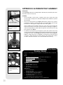
Appendix B: Alternate Tray ASssembly..........................24
Basic Astronomy ............................................................25
TELESCOPE FEATURES
G
F E
D
C
B
H
1&
I
1^
J
1)
1!
1%
1@
1#
1$
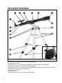
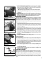
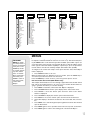
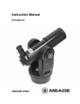
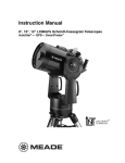
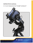
Fig. 1: The NGC telescope. Inset: Alternate tray style.
Your telescope may look different from the one depicted above.
Some differences include:
• NG models do not include a control panel (4, Fig. 1) or a battery compartment (18, Fig. 2)
• 90° diagonal mirror styles vary (8, Fig. 1 or 28, Fig. 4 inset)
• Some models include 1.25" diameter eyepieces; other models include .965" diameter eyepieces (7, Fig. 1)
• Viewfinder bracket (6, Fig. 4 and inset) styles vary
• Accessory tray styles vary
• Model colors vary
• Some models include a focus lock knob (27, Fig. 4 inset)
4
E
1*
B
A
1(
C
D
EF
2)
G
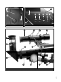
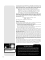
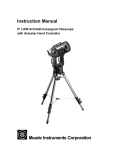
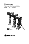
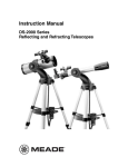
Fig. 2: Top view of the NGC base.
Fig. 3: Detailed view of the NGC computer control panel.
2@
2#
G
2!
2&
2*
H
2%
2^
2$
I
J
1)
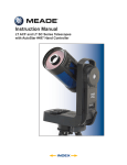
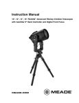
Fig. 4: Detailed view of the focuser assembly and the viewfinder. Inset: Alternate style focuser and viewfinder.
5
Telescope and Tripod Features
6
b
Dust Cap (not shown): Pull to remove from the dew shield (17, Fig. 1).
NOTE: The dust cap should be replaced after each observing session and
the power turned off (NGC models only) to the telescope. Verify that any
dew that might have collected during the observing session has evaporated prior to replacing the dust cap.
C
Optical Tube: The main optical component that gathers the light from distant
objects and brings this light to a focus for examination with the eyepiece.
D
Optical Tube Attachment Bracket: Attach the optical tube to this bracket. See
HOW TO ASSEMBLE YOUR TELESCOPE, page 8, for more information.
E
Control Panel (Fig. 3, NGC Models Only):
A. 2-Line LCD Display: Displays menus and information concerning the computer controller.
• Top line: Displays menu items.
• Bottom line: Displays menu options or information. For example,
information about an astronomical object, such as a planet, or
information about locating an object.
B. Enter Button: Accesses, in order, the next menu or option. When a menu
option you wish to choose displays, press ENTER to select it. This button is
similar to a computer's RETURN key.
C. Mode Button: Press this button when you wish to return to the previous
menu. The MODE key is similar to a computer's ESCAPE key.
If MODE is pressed and held for two seconds or more, the following information displays:
• Astronomical coordinates of a selected object
• Local Time and Local Sidereal Time (LST)
• Timer and Alarm Status
Press MODE again to return to the previous menu.
D. Up/Down Button: Use UP/DOWN to scroll through the letters of the alphabet, numerical digits, menus, menu options and other information.
E. On/Off: Press to turn the control panel on or off.
F. Vertical Slow Motion Control Knob: Use this control to make fine adjustments in the vertical movement of the telescope.
G. Aux Port: Use this port, along with the optional #506 Astrofinder Software and
Cable Connector Kit, to connect to your PC, or to update celestial objects for
your control panel from the Meade website (www.meade.com). See
OPTIONAL ACCESSORIES, page 19, for more information.
F
Optical Tube Attachment Knobs: Attach these knobs to the bolts on the optical
tube when you attach the optical tube to the bracket. See HOW TO ASSEMBLE
YOUR TELESCOPE, page 8, for more information.
G
Viewfinder: Before looking at an object in the eyepiece, locate the object in the
viewfinder. The viewfinder provides a much easier way to locate celestial objects
than a telescope eyepiece, because it has a much wider field of view.
H
Eyepiece: Place the eyepiece into the 90° diagonal mirror (8, Fig. 1 or 28, Fig. 4)
and tighten the thumbscrew (25, Fig. 4) to a firm feel only. You may also place the
eyepiece directly into the focuser drawtube (9, Fig. 1). Use the focus knobs (10,
Fig. 1) to focus the eyepiece.
I
90° Diagonal Mirror, Style 1: Holds the eyepiece at a convenient angle for easy
viewing. Slide the diagonal mirror into the focuser drawtube (9, Fig. 1) and tighten
the thumbscrew (26, Fig. 4) to a firm feel only.
J
Focuser Drawtube: Slide the diagonal mirror or an eyepiece into this tube.
Tighten the thumbscrew (26, Fig. 4) to a firm feel only.
1)
Focus Knobs: Use to move the telescope’s focuser assembly to obtain precise
image focus. Rotate the focus knobs clockwise to focus on distant objects, and
counterclockwise to focus on nearby objects.
1!
Tripod Leg Nuts and Bolts (3): Attach the tripod legs (15, Fig. 1) to the tripod
head (16, Fig. 1) using these three nuts and bolts. See HOW TO ASSEMBLE YOUR
TELESCOPE, page 8, for more information.
1@
Tripod Struts: Attach the struts to accessory tray. See HOW TO ASSEMBLE YOUR
TELESCOPE, page 8, for more information.
1#
Tripod Leg Lock (3): Lift the lock to loosen the inner section of a tripod leg and
extend the inner leg to the desired height. Press the lock down to lock the leg
again.
1$
Accessory Tray: Use the tray to hold extra eyepieces during your observing sessions.
1%
Tripod Legs: Attach the legs to the tripod head (16, Fig. 1). See HOW TO ASSEMBLE YOUR TELESCOPE, page 8, for more information. When observing, spread the
legs out as far as they will open for a secure viewing platform.
1^
Base/Tripod Head: Supports the telescope for placement on the tripod. See HOW
TO ASSEMBLE YOUR TELESCOPE, page 8, for more information.
1&
Dew shield: Reduces the formation of dew on the telescope's primary lens and
acts as a shade for daytime use.
1*
Battery Compartment Lid (NGC Models Only): Remove the lid to install one
user-supplied 9v battery in this compartment. See HOW TO ASSEMBLE YOUR
TELESCOPE, page 8, for more information.
1(
Compass/Bubble Level NGC Models Only): Use the compass to locate North
while aligning the telescope. See EASY ALIGNMENT, page 12, for more information. Note that the compass is positioned next to an arrow etched onto the base.
When the arrow of the compass and the etched arrow both point in the same
direction, the telescope is then pointed North.
Use the bubble level to help level the base of your tripod. When the bubble is in
the center of the compass, the base is level.
2)
Horizontal Slow Motion Control Knob (NGC Models Only): Use this control to
make fine adjustments in the horizontal movement of the telescope.
2!
2@
Viewfinder Lens: Gathers light for the viewfinder.
2#
Viewfinder Eyepiece and Rubber Cup: Turn the viewfinder eyepiece, if necessary, to focus the viewfinder. The rubber cup may be removed, if so desired.
2$
Viewfinder Bracket: Holds the viewfinder in place. Attach to the optical tube. See
HOW TO ASSEMBLE YOUR TELESCOPE, page 8, for more information.
2%
Diagonal Mirror Thumbscrew: Tightens the eyepiece in place. Tighten to a "firm
feel" only.
2^
Focuser Drawtube Thumbscrew: Tightens a diagonal mirror or an eyepiece in
place. Tighten to a firm feel only.
2&
Focus Lock Knob (Fig. 4 inset): This feature is designed to prevent the focuser
drawtube from moving when a heavy accessory, such as a camera, is attached to
the focuser assembly. For normal observing with an eyepiece and diagonal mirror, it is not necessary to use the lock knob.
2*
90° Diagonal Mirror, Style 2 (Fig. 4 inset): Holds the eyepiece at a convenient
angle for easy viewing. Slide the diagonal mirror into the eyepiece holder and
tighten the thumbscrew to a firm feel only.
NOTE: Sometimes air
gets trapped below the
compass dial causing
the compass to not
work properly.
Gently tap the battery
cover to insure that no
air is trapped below the
compass dial.
Viewfinder Alignment Screws: Adjust these screws to align the viewfinder. See
ALIGNING THE VIEWFINDER, page 9, for more information.
7
GETTING STARTED
Parts Listing
•
•
•
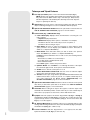
Insert
bolt
Fig. 5: Attach tripod legs to the tripod
head.
Fig. 6: Tighten screws with screwdriver
tool to attach tray to the struts (Style 1).
Fig. 7: Attach pin to tripod leg bracket
with a large pliers (Style 2).
Fasten
wing nuts
Fig. 8: Attach tray to the tripod: Thread
the wing nuts to the bolts (bottom view;
Style 2).
8
Complete 60mm diameter optical tube assembly with dew shield, dust cap,
5 x 24 viewfinder, and rack-and-pinion focuser; electronic control panel (NGC
models only).
Continuously adjustable aluminum tripod and leg braces.
Accessories:
Eyepieces and 90° diagonal mirror
Accessory tray
3 screws (3/8" long) with wing nuts and screwdriver tool
3 screws (1 9/16" long) with hex nuts
2 nuts for attaching optical tube to bracket (certain models)
3 cylindrical pins (certain models)
How to Assemble Your Telescope
Note that although the telescope is unassembled, all of the more difficult or complicated sections of the instrument are already factory pre-assembled. To set up the telescope, follow this procedure:
1. Identify: Remove from the gift box and identify the telescope’s components,
using the listing above.
2. Tripod setup: The tripod is shipped with the tripod head and the tripod legs unattached. Attach the 3 aluminum tripod legs (15, Fig. 1) to the tripod head (16, Fig.
1) with the 3 leg locks facing inward. Three 1 9/16" long bolts and hex nuts are
provided for this purpose. See Fig. 5. Spread the tripod legs evenly apart.
3. Attach the accessory tray: Your telescope comes supplied with one of two different tray styles.
Style 1: Attach the accessory tray (14, Fig. 1) to the leg brace supports (12, Fig.
1) using the three provided 3/8" long screws and the wing nuts. Place the accessory tray on top of one of the leg brace supports of the tripod so that the mounting screw passes through the hole at one of the corners of the accessory tray,
and through the slot in the leg brace support. Then thread-on the wing nut and
tighten the screw using the provided screwdriver tool. See Fig. 6. Repeat this
procedure until all 3 corners are mounted to the 3 leg braces.
Style 2: Attach the inner support struts to the tripod legs using the provided pins.
Line up the cylinder on the end of each strut between the holes on the bracket
on each tripod leg. Use a large pliers to squeeze the pins into the bracket assembly. See Fig. 7. Place the tray (14, Fig. 1) over any one of the inner support struts.
Line up the bolts on the tray with the bolt holes on the strut. Slide the two provided bolts through the top of the bolt holes and tighten with the included wing
nuts on the bottom side of the tray (Fig. 8). Tighten to a firm feel only.
Note: This style tray does not have to be removed when you collapse the tripod
at the end of a viewing session.
Style 3 (Round Tray): See APPENDIX B, page 24.
4. Set tripod leg height: Lift the tripod leg lock (13, Fig. 1) and extend the sliding
center portion of the adjustable height tripod leg (15, Fig. 1) to the desired length.
Press the leg lock down to lock.
5. Attach the optical tube to bracket: Your telescope comes supplied with one of
two styles of optical tube attachment.
Style 1: Two bolts extend from the center portion of the optical tube (2, Fig. 1).
Slide the bolts through the holes in the bracket (3, Fig. 1). Thread the provided
attachment nuts over the bolts and tighten to a firm feel. See Fig. 9a.
Style 2: Unthread the cradle lock knob to open the cradle ring. Place the optical
tube into the cradle ring. Tighten the lock knob so that it holds the tube loosely.
Balance the tube: Slide the tube back and forth until you find a position where the
tube remains horizontal (i.e., without tipping up or down). Now tighten the cradle
ring lock knob to a firm feel. See Fig. 9b.
Note: If the horizontal and/or vertical movement of the optical tube seems to
be too loose or too tight, you can adjust the amount of tension in the movement of the tube to suit your own preference. See ADJUSTING THE
HORIZONTAL AND VERTICAL TENSION OF THE OPTICAL TUBE, page 20.
6.
Bracket
Attachment
Nuts
7.
8.
Insert the diagonal mirror and eyepiece: Insert the diagonal mirror (8, Fig. 1)
into the focuser drawtube (9, Fig. 1) and a low-power eyepiece (e.g., 25mm or
26mm eyepiece) into the diagonal mirror. Tighten the eyepiece and diagonal mirror thumbscrews (25 and 26, Fig. 4) to a firm feel.
Note: Some models are supplied with one of two styles of the 90° diagonal
mirror. Quantities of eyepieces and eyepiece size varies with each model.
Install battery (NGC Models Only): Lift the lid of the battery compartment (18,
Fig. 2) and attach a 9v battery (user-supplied) to the connector provided in the
compartment.
Remove dust cap: Pull to remove the dust cap from the end of the telescope.
Replace it on the telescope at the end of the observing session. The cap keeps
the telescope lens free from dust and foreign particles when it is not in use.
Aligning the Viewfinder
Fig. 9a: Attach optical tube to the
mount (Style 1).
Cradle
Lock
Knob
Fig. 9b: Attach optical tube to cradle
ring (Style 2).
Fig. 10a: Attach viewfinder to the optical tube (Style 1).
Because the main telescope has a fairly narrow field of view, locating objects directly
in the main telescope can sometimes be difficult. The viewfinder (6, Fig. 1) is a small,
wide-field telescope with crosshairs that permits you to more easily locate objects.
When the viewfinder and optical tube are aligned to each other, both point to the same
position in the sky. An object located in the viewfinder is therefore also positioned
within the field of the main telescope.
1. Attach viewfinder bracket (Style 1): Remove the two attachment thumbscrews
from the optical tube. These screws are pre-threaded at the factory into the optical telescope tube at the viewfinder location. Line up the holes in the viewfinder
bracket with the holes on the tube and thread the thumbscrews back onto the
main tube. See Fig. 10a.
Attach viewfinder bracket (Style 2): Using a Phillips head screwdriver, thread
the two attachment screws in the bracket (these screws are placed inside the
bracket at the factory) into the mating threads on the optical tube. See Fig. 10b.
2. Attach viewfinder: Remove the rubber cup from the viewfinder tube and slide
the tube into the viewfinder bracket. Orient the viewfinder as depicted in Fig. 4.
Loosely tighten the collimation screws. You will use these screws to align the
viewfinder; see TO ALIGN THE VIEWFINDER, below. Re-attach the rubber cup onto
the viewfinder.
3. Focusing the Viewfinder: Turn the viewfinder eyepiece on its internal thread.
Generally a few turns are sufficient to achieve proper focus.
To Align the Viewfinder:
It is recommended that you perform steps 1 and 2 of this procedure during the daytime and step 3 at night.
1. If you have not already done so, place a low-power (e.g., 25mm or 26mm) eyepiece in the diagonal mirror of the main telescope (8, Fig. 1) and point the telescope at an easy-to-find land object (e.g., the top of a telephone pole). Turn the
focuser knob (10, Fig. 1) so that the image is sharply focused. Center the object
precisely in the main telescope’s field of view.
2. Then, looking through the viewfinder, turn some or all of the viewfinder’s alignment screws (22, Fig. 4) until the viewfinder’s crosshairs point precisely at the
same object as centered in the main telescope. The viewfinder is now aligned to
the main telescope. Now tighten the screws to hold the tube securely; be careful
not shift the tube's alignment.
3. Check this alignment on a celestial object, such as the Moon or a bright star, and
make any necessary refinements.
Choosing an Eyepiece
Fig. 10b: Attach viewfinder to the optical tube (Style 2).
A telescope’s eyepiece magnifies the image formed by the telescope’s main optics.
Each eyepiece has a focal length, expressed in millimeters, or "mm." The smaller the
focal length, the higher the magnification. For example, an eyepiece with a focal length
of 12.5mm has a higher magnification than an eyepiece with a focal length of 25mm.
Low-power eyepieces (e.g., a 25mm or 26mm eyepiece) give a wide, comfortable field
of view with high image resolution. High-power eyepieces (e.g., a 12.5mm or 4mm eyepiece) provide a smaller field of view but higher magnification when seeing conditions
permit.
9
Low power eyepieces offer a wide field of view, bright, high-contrast images, and eye
relief during long observing sessions. To find an object with a telescope, always start
with a low power eyepiece (e.g., 25mm or 26mm eyepiece). When the object is located and centered in the eyepiece, you may wish to switch to a higher power eyepiece
to enlarge the image as much as practical for prevailing seeing conditions.
NOTE: Seeing conditions vary widely from night-to-night and site-to-site.
Turbulence in the air, even on an apparently clear night, can distort
images. If an image appears fuzzy and ill-defined, back off to a lower
power eyepiece for a more well-resolved image (Figs. 11a and 11b).
The power, or magnification of a telescope is determined by the focal length of the telescope and the focal length of the eyepiece being used. To calculate eyepiece power,
divide the telescope's focal length by the eyepiece's focal length. E.g., a 25mm eyepiece is used with a NGC60 telescope. The focal length of the NGC60 is 700mm (see
SPECIFICATIONS, page 21).
Focal length ÷ Eyepiece focal length = Power
700mm ÷ 25mm = 28
The eyepiece power, or magnification is therefore 28x.
Simple Observations
If you wish to observe a distant land object, such as a mountain top, you can observe
by merely pointing the telescope and looking through the eyepiece.
•
Move your telescope to observe distant street signs, mountains, trees and other
structures. Use your viewfinder to help site-in on an object.
•
Practice focusing objects with the focus knob (10, Fig. 1).
•
Once you get a feel for how your telescope moves and focuses, try to view something more challenging, like a bird or a distant moving train.
You can also observe stars and objects in the night sky using this method, but note
that objects begin to slowly drift across the eyepiece field. This motion is caused by
the rotation of the Earth. You'll find that you will need to reposition your telescope from
time to time to keep an object in the eyepiece field of view. This is especially true when
using high-power eyepieces.
Viewing terrestrial objects requires looking along the Earth's surface through heat
waves. These heat waves often cause loss of image quality. Lower power eyepieces,
such as 25mm or 26mm eyepieces, magnify these heat waves less than higher power
eyepieces. Therefore, lower power eyepieces provide a steadier, higher quality image.
If the image is fuzzy or ill-defined, reduce to a lower power eyepiece, where the heat
waves do not have such an effect on image quality. Observing in early morning hours,
before the ground has built up internal heat, produces better viewing conditions than
during late afternoon hours.
If you have an NGC model telescope, you can locate stars and other celestial objects
(over 1400 objects in all) using the control panel. In order to do so, you must initialize
the control panel, set the telescope in the home position, and align the telescope. The
control panel uses this information to determine the location of celestial objects.
TIPS for Beginners
Too Much Power?
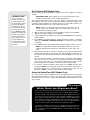
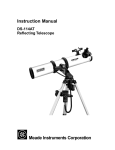
Fig. 11a & 11b: Jupiter; examples of
the right amount of magnification
and too much magnification.
Can you ever have too much power? If the type of power you’re referring to is
eyepiece magnification, yes, you can! The most common mistake of the beginning observer is to "overpower" a telescope by using high magnifications which
the telescope’s aperture and atmospheric conditions cannot reasonably support.
Keep in mind that a smaller, but bright and well-resolved image is far superior to
one that is larger, but dim and poorly resolved (see Figs. 11a and 11b). Powers
above 200X should be employed only under the steadiest atmospheric conditions.
Most observers should have three or four additional eyepieces to achieve the full
range of reasonable magnifications. See OPTIONAL ACCESSORIES, page 19.
10
Initializing the Control Panel (NGC Models Only)
1.
2.
3.
4.
5.
6.
7.
8.
9.
Make sure that you have installed a 9v battery in the battery compartment.
Press ON/OFF to turn the power on.
The control panel display lights up and a copyright message displays briefly.
A message displays that warns you not to use the telescope to look at the Sun.
At the end of this message, press the button prompted by the display to signify
that the message has been read and understood.
The control panel display then requests the current date. Use UP/DOWN (D, Fig.
3) to scroll through the digits for the date. Press ENTER after each of the desired
digits displays and the cursor will move to the next position.
After the date is entered, the month list displays. Use UP/DOWN to scroll through
the list of months. When the current month displays, press ENTER.
The cursor moves to the year display. Use UP/DOWN to scroll through the digits
for the year. Press ENTER when each of the desired digits displays and the cursor will move to the next position.
The control panel then requests the current time. Use UP/DOWN to display the
digits for the time. (Use a "0" for the first digit if less than 10.) Press ENTER after
each of the desired digits displays and the cursor will move to the next position.
After the time is entered, "AM" is displayed. Note that there are three options in
this setting: "AM," "PM" and "blank" (neither AM nor PM is displayed). If you
select the "blank" option, the clock displays time in a 24-hour (military time) format. Use UP/DOWN to scroll to your choice. Press ENTER to start the clock.
The next screen requests the status of Daylight Savings Time. Use UP/DOWN to
move between the "Yes" and "No" settings. Select the desired setting by pressing ENTER.
NOTE: Daylight Savings Time may be referred to by a different name in
various areas of the world.
NOTE: When multiple choices are available within a menu option, the current option is usually displayed first and highlighted by a right pointing
arrow (>).
The next screen asks for the country or state/province (listed alphabetically) of
the observing site.
Note: The location settings (country/state/province and city) are only
asked for the first time you turn on the control panel. If you wish to change
this setting later on, use the Site menu. See SITE, page 18, for more information.
Use UP/DOWN to scroll through the list of countries, states, and provinces. Press
ENTER when the correct location displays.
The next screen asks for the city (listed alphabetically) closest to the observing
site. Use UP/DOWN to scroll through the list of cities. Press ENTER when the
correct city appears on screen.
System initialization is complete. The Easy Alignment feature begins automatically after the control panel is initialized. See Easy Alignment, page 12.
How to set the time and date to 11:30 PM, March 6, 2003 (NGC Models Only):
This example demonstrates how to set the time and date.
1. Press ON/OFF to turn on the control panel.
2. Press the button prompted by the control panel to show that the Sun warning has
been read and understood.
3. "Enter Date: 01-JAN-2003" displays. "0" is highlighted by a blinking cursor. Press
ENTER to select "0."
4. "1" is now highlighted. Press UP/DOWN until "6" displays in this position. Press
ENTER.
5. "JAN" is now highlighted. Press UP/DOWN until "MAR" displays and press
ENTER.
6. "2" is now highlighted. The date display now reads "06 MAR 2003." Press
ENTER four times to accept the year without any changes.
11
7. "Enter Time: 08:00:00AM" displays. The leftmost "0" is highlighted. Press
UP/DOWN until "1" displays. Press ENTER.
8. "8" is highlighted. Press UP/DOWN until "1" displays. Press ENTER.
9. "0" is highlighted. Press UP/DOWN until "3" displays. Press ENTER.
10. Keep pressing ENTER until "AM" is highlighted. Press UP/DOWN until "PM" displays. Press ENTER.
11. The time display now reads "11:30:00PM."
Easy Alignment (NGC Models Only)
1.
2.
NOTE: Sometimes air
gets trapped below the
compass dial causing
the compass to not
work properly.
Gently tap the battery
cover to insure that no
air is trapped below the
compass dial.
Note: If the horizontal
and/or vertical movement of the optical
tube seems to be too
loose or too tight, you
can adjust the amount
of tension in the movement of the optical
tube to suit your own
preference. See
3.
4.
ADJUSTING THE
HORIZONTAL AND
VERTICAL TENSION OF
THE OPTICAL TUBE,
page 20.
NOTE: The control
panel locates alignment
stars based on the
date, time, and location
entered. The alignment
stars may change from
night to night.
12
5.
6.
Easy Align: Once the control panel is initialized, the control panel automatically
begins the Easy Alignment procedure.
Set Home Position: The control panel prompts you to set the telescope in the
home position. To set your telescope in the home position:
Adjust the length of the legs of the tripod until the bubble in the bubble level
•
is in the center of the compass.
•
Rotate the base of the telescope until the arrow in the compass points in
the same direction as the arrow etched into the base. The telescope is now
pointing North.
Push down the front end of the optical tube (the end with the dew shield)
•
until it stops.
When you have finished setting the telescope in the home position, press
ENTER.
Star Alignment: After the home position is entered, the control panel searches
its database for two alignment stars, and displays "Searching" while it does so.
The control panel uses these stars to orient itself to the sky. Once it is oriented,
it knows the location of any celestial object in its database.
For example, the control panel may search its database and choose Alkaid, the
tail star of the Big Dipper, as the first alignment star. It displays "Ctr. Alkaid" on
the top line and "Then Press Enter" flashes three times on the second line. This
is a reminder that after you center a star in the eyepiece (see step 5 below), you
need to press ENTER. But do not press ENTER yet.
After displaying "Then Press Enter," the control panel displays two numbers on
the second line. For example: "Ctr. Alkaid: +35 -115." These two numbers are
called "displacement numbers" and will assist you in locating a celestial object.
Move the telescope: Move the telescope tube to the right or left and you will
notice the first displacement number getting larger or smaller. Move the tube in
the direction that makes the number smaller. Keep moving the tube until the number nears zero. As you near zero, bars appear on the display to make it easier to
precisely reach zero. Use the horizontal slow motion control (20, Fig. 2) to move
the tube in small increments.
After the first displacement number displays zero, move the tube upwards until
the second displacement number also nears zero. As you near zero, bars appear
on the display to make it easier to precisely reach zero. As you near zero, use
the vertical slow motion control (F, Fig. 3) to move the tube. You probably will
need to make fine adjustments with both displacement numbers as moving the
optical tube may slightly shift one or the other displacement numbers.
After both number have reached zero, the first alignment star may not appear in
the field of view of the eyepiece. However, the alignment star should be easily
recognized and be the brightest star in the area of the sky where the telescope
is pointing. Look for the star in the viewfinder to see if you can locate it. The
viewfinder has a wider field of view than the eyepiece. See WHICH ONE'S THE
ALIGNMENT STAR, page 13, for more information.
Center the Star: Once you locate the star, adjust the optical tube using the horizontal and vertical slow motion controls until the star is visible and centered in
the eyepiece. When the star is centered, press ENTER.
Repeat the procedure for the second alignment star. If you have have followed
the procedure correctly, "Align Successful" displays and the telescope is aligned.
You may now use the control panel to locate other stars and objects in the sky. If
your alignment was unsuccessful, "Align Unsuccessful" and then "Setup: Easy
Align" displays. Press ENTER and repeat the procedure.
Go To Saturn (NGC Models Only)
After performing the Easy Alignment procedure, the telescope is aligned for a night of
viewing.
IMPORTANT NOTE:
As you observe
Saturn, you will notice
that the image moves
in the eyepiece. This is
because the Earth is
rotating. You can use
the horizontal and vertical slow motion controls (20, Fig. 2 and F,
Fig. 3) to re-center the
image in the eyepiece.
The image will move
much faster if you are
using a higher-powered eyepiece such as
a 4 mm or the 12mm
eyepiece.
IMPORTANT NOTE: Once aligned, do not move the telescope's tripod
and base from the level position or alignment will be lost.
This exercise demonstrates how to select an object for viewing from the control
panel's Object menu. The control panel provides an Object menu which displays a list
(sometimes called a database) of over 1400 objects you can view with your telescope.
This example demonstrates how to select Saturn from the list.
1
2.
3.
4.
5.
6.
7.
NOTE: Saturn is not visible the entire year and you may need to choose
another object from the Object menu list; however, the procedure, as
described below, remains the same.
After the telescope is aligned, "Select Item: Object" displays. Press ENTER.
"Object: Solar System" displays. Press ENTER.
"Solar System: Mercury" displays. Keep pressing UP/DOWN until "Solar System:
Saturn" displays.
Press ENTER. "Calculating" displays. "Saturn" and its R.A. and Dec. coordinates
display. See APPENDIX A: ADVANCED FEATURES, for information about celestial
coordinates.
Press ENTER. Next, Saturn's displacement numbers display: "Saturn: +14 -135."
NOTE: Your displacement numbers will be different than the ones in this
example. Displacement numbers are determined by location, time, and
date.
Move the telescope tube to the right or left until you notice the first displacement
number getting smaller. Keep moving the tube until the number reaches zero. As
you near zero, use the horizontal slow motion control (20, Fig. 2) to move the optical tube.
Next, move the tube upward or downward until the second displacement number
also reaches zero. As you near zero, use the vertical slow motion control (F, Fig.
3) to move the optical tube. If you performed the alignment procedure correctly,
Saturn will appear in your eyepiece. You may need to center the image.
If you wish to display information about Saturn, press MODE and then keep
pressing UP/DOWN to scroll through various lines of information. The last line of
information displays as a scrolling message. As the message scrolls, you can
press UP or DOWN to increase or decrease the scrolling speed.
Using the Guided Tour (NGC Models Only)
The control panel provides a Guided Tour menu that displays the best objects (and
their displacement numbers) to view on any given night of the year. This example
demonstrates how to use the "Tonight’s Best" Guided Tour. Other Guided Tours are
also provided.
TIPS for Beginners
Which One’s the Alignment Star?
If the control panel has chosen an alignment star with which you are unfamiliar,
how can you be sure if the star in your eyepiece is really the alignment star?
The rule of thumb is that an alignment star is usually the brightest star in that
area of the sky. If you're not sure if you have located the alignment star or it isn't
in the eyepiece, look through your viewfinder. When you view an alignment star
in the viewfinder, it stands out dramatically from the rest of the stars in that portion of the sky. The viewfinder will help you locate a star more quickly than the
eyepiece, because it has a much wider field of view than the eyepiece.
If you have an obstruction, such as a tree or a building blocking your view of the
alignment star, or if you have any doubts at all about the star that has been chosen, no problem. Just press UP/DOWN and the control panel will find another
star to align upon.
13
1.
After observing Saturn, press MODE twice so that "Select Item: Object" displays
again.
Press UP/DOWN until "Select Item: Guided Tour" displays.
Press ENTER. "Guided Tour: Tonight’s Best" displays. Press ENTER.
NOTE: If you wish to try out other Guided Tours, press UP/DOWN to
scroll through other tour choices. When the tour you wish to select displays, press ENTER.
"Tonight’s Best: Searching..." displays. After calculating, "Tonight’s Best: Jupiter"
displays.
NOTE: Different objects may be displayed on a tour list on any given night.
Use the method described in the last section, GO TO SATURN, to find Jupiter or
any other object displayed on the Guided Tour list. After selecting an item from
the list by pressing ENTER, press UP/DOWN to display information about the
object.
Press MODE to return to the Tour list. Press UP/DOWN to scroll through the list.
Press ENTER when you find the next object you wish to observe.
Use MODE to leave the Guided Tour menu.
2.
3.
4.
5.
6.
TIPS for Beginners
Observing Considerations
•
Try to pick an observing site away from street and house lights and car headlights.
While this is not always possible, the darker the site, the better.
•
Give your eyes about ten minutes to adjust to the darkness before observing. Give
your eyes a rest from observing every ten or fifteen minutes to relieve eyestrain.
•
Try not to use a standard flashlight. Experienced observers use red LED flashlights
or tape red cellophane over their flashlights to use for setup and map reading so
they don’t have to continually readjust their eyes to the darkness. Be careful not to
shine bright lights if there are other observers in the area. Do not shine a flashlight
into the telescope while someone is observing!
•
Dress warmly. It gets chilly when you’re sitting for prolonged periods, even on
warm nights.
•
Practice setting up your equipment during the day or in a lighted area to become
familiar with it before going to a dark site.
•
Use a 25mm or 26mm eyepiece to view terrestrial objects and wider areas of
space, such as open star clusters. Use optional higher power eyepieces, such as
a 12.5mm eyepiece (see OPTIONAL ACCESSORIES, page 19, for more details),
when you wish to view something up close, such as craters on the Moon or the
rings of Saturn.
Surf the Web
One of the most exciting resources for astronomy is the internet. The internet is full of websites with new images, discoveries, and the latest astronomical information. You can find
websites for almost any topic relating to astronomy on the internet. Check out Meade’s
website for the latest product and technical information. You’ll find our website at:
http://www.meade.com/
Here are some other sites you might find interesting:
•
Sky & Telescope:
http://www.Sky and Telescope.com
•
Astronomy:
http://www.astronomy.com
•
Astronomy Picture of the Day:
http://antwrp.gsfc.nasa.goc/apod
•
Heavens Above (satellite observing information):
http://www.heavens-above.com
•
Photographic Atlas of the Moon:
http://www.lpi.ursa.edu/research/lunar_orbiter
•
Hubble Space Telescope Public Pictures
http://oposite.stsci.edu/pubinfo/pictures.html
14
Select Item:
Object
Solar System
Mercury
Etc.
Moon
Asteroids
Comets
Constellations
Andromeda
Etc.
Deep Sky
Named Object
Galaxies
Nebulae
Planetary Neb.
Etc.
Star
Named
SAO Catalog
Double
Etc.
User Objects
Select
Add
Delete
Edit
Landmarks
Select
Add
Delete
Identify
Select Item:
Event
Sunrise
Sunset
Moonrise
Moonset
Moon Phases
Next Full Moon
Next New Moon
Next 1st Qtr
Next 3rd Qtr
Meteor Showers
Quadrantids
Lyrids
Eta Aquarids
Delta Aquarids
Perseids
Orionids
Taurids
Leonids
Geminids
Ursids
Solar Eclipses
Lunar Eclipses
Min. of Algol
Autumn Equinox
Vernal Equinox
Winter Solstice
Summer Solstice
Select Item:
Guided Tour
Tour Objects
Tonight's Best
How Far is Far
A Star's Life
Messier Marathon
Select Item:
Glossary
A...
Accretion Disk
Etc.
B...
C...
D...
E...
F...
G...
H...
I...
J...
K...
L...
M...
N...
O...
P...
Q...
R...
S...
T...
U...
V...
W...
X...
Y...
Z...
Select Item:
Utilities
Timer
Set
Start & Stop
Alarm
Set
On & Off
Eyepiece Calc.
Field of View
Magnification
Suggest
Brightness Adj.
Contrast Adj.
Select Item:
Setup
Easy Align
Date
Time
Daylight Saving
Site
Select
Add
Delete
Edit
Download
Statistics
Reset
Fig. 12: The NGC Menu structure.
MENUS
IMPORTANT
NOTE: No matter
how many levels of
menus are traveled,
each press of the
MODE key moves
up a level, until the
top level, "Select
Item," is reached.
Once in the Select
Item level, press
MODE to return to
the topmost level,
"Select Item:
Object."
How to move through menu options (NGC Models Only):
It is helpful to understand that menu selections are set in a loop. This means that pressing the DOWN button scrolls down through all the available options within a given category, then returns to the first option. Pressing the UP key scroll up through the options
in the opposite order. Note that this capability is a quick way to get to an option that is
near the bottom of the list. The following example demonstrates this capability.
To navigate to the "Select Item: Setup" menu option when the "Select Item: Object"
menu is displayed:
1. Press DOWN five times or UP once.
When the desired option is displayed on the second line, press the ENTER key to
choose that option and move down one menu level.
Press the MODE key to leave a level; e.g., the wrong menu option is chosen.
How to Calculate Sunset time (NGC Models Only):
This example demonstrates how to move through a typical menu and calculate Sunset
time. This is an excellent exercise to try out as you can calculate the time when it is
going to get dark—and when you can start observing.
1. Press MODE several times, until "Select Item: Object" is displayed.
2. Press UP/DOWN until the "Event" option displays in the "Select Item" menu.
3. Press ENTER to choose the "Event" option and move down a level. "Event:
Sunrise" is displayed.
4. Press UP/DOWN to display the "Sunset" option in the Event menu.
5. Press ENTER to choose the "Sunset" option and move down another level.
6. Sunset time displays; calculations are based on the current date, time, and location.
7. Press MODE once to start moving back up through the menu levels. The first level
up is the Event menu.
8. Press MODE again to move up another level. This is the top level, "Select Item."
9. Press MODE again to return to the starting point of "Select Item: Object."
15
Object Menu
IMPORTANT NOTE:
To use the Select
and Add features of
the Landmark menu,
the telescope must
be physically located in the same
place it was located
when the landmark
list was created.
Also, the optical
tube must be pointed at and centered
on the first object in
the Landmark list.
Almost all observing is performed using the Object menu category. (NOTE: Exceptions
include Guided Tour and Landmark Survey.) See GO TO SATURN, page 13, for an
example of observing using the Object menu. Also see USING THE GUIDED TOUR, page
13.
The Object Menu includes:
Solar System is a list of the eight planets (Earth is not included) in order out from the
Sun, followed by the Moon, asteroids, and comets.
Constellation is a list of all 88 Northern and Southern Hemisphere constellations.
When this option is chosen and a constellation name displays (e.g., "Constellations:
Aquarius"), press ENTER to select the constellation. You can use UP/DOWN to display lines of information about that constellation on the second line of the display.
Press ENTER when the name of a constellation is displayed to display the name of
the brightest star in the constellation. Use UP/DOWN to cycle through the list of
important stars in the constellation (these are generally the stars that make up the
shape of the constellation), from brightest to dimmest. When the desired star is displayed, press ENTER to select it. You may now use UP/DOWN to scroll through lines
of information about the selected star, such as the star's celestial coordinates, brightness, and so forth. The last line of information displays as a scrolling message. As the
message scrolls, you can press UP or DOWN to increase or decrease the scrolling
speed.
If you press ENTER when information about the star displays, the displacement numbers then display, which tell you how to move the optical tube to locate the star. See
GO TO SATURN, page 13, for more information about using displacement numbers to
locate an object. Use MODE to exit this menu.
Deep Sky is a list of objects outside our Solar System such as nebulae, star clusters,
galaxies, and quasars.
Star is a list of stars listed in different categories such as named, double, variable, or
nearby.
User Objects allows the user to create his or her own list of celestial objects that are
not currently in any other list. See APPENDIX A, page 22, for more information.
Landmarks stores the location of terrestrial points of interest in the permanent user-created list in the control panel database.
•
Select: To select a Landmark already in the database, choose the "Select" option
and use UP/DOWN to scroll through the list. Press ENTER to select a Landmark.
See LANDMARKS, page 24, for a detailed procedure.
•
Add: To add a Landmark, choose the "Add" option. Enter a name for the
Landmark. Locate and center the Landmark, then press ENTER. Note that you
must be aligned with other landmarks for this feature to work properly. See LANDMARKS, page 24, for a detailed procedure.
Identify is an exciting feature for an observer who wants to scan the night sky and
start exploring. Use this feature after the telescope has been properly aligned. Then
follow this procedure:
1. When a desired object is visible in the eyepiece, keep pressing MODE until the
"Select Item: Object" menu is displayed. Then press ENTER.
2. Use UP/DOWN to scroll through the Object menu options until the "Object:
Identify" screen appears.
3. Press ENTER. The computer control panel searches its lists for the identity of the
object being observed.
4. If the object is not in the computer's control panel database, the nearest object in
the database is located and displayed on the screen, along with the object's
celestial coordinates. Press ENTER and the displacement numbers for the object
display. Use the displacement numbers to go to the object, as described in GO
TO SATURN, page 13.
Event Menu
The Event menu allows you to display the dates and times of astronomical events.
The Event feature includes:
16
NOTE: Meteors are
fast moving objects
that cover large
areas of the sky
and are usually
best observed with
the naked eye.
NOTE: The equinox and the solstice are the days
of the year when
the seasons
change. These
days are determined by the location of the Sun in
the sky. Vernal
means spring.
Sunrise and Sunset calculates the time that the Sun rises or sets on the current date
and location. Find rise and set times for other dates by entering a new date into the
"Setup: Date" menu.
Moonrise and Moonset calculates the time that the Moon rises or sets on the current
date and location. Find rise and set times for other dates by entering a new date into
the "Setup: Date" menu.
Moon Phases displays the date and time of the next Full, New, 1st Quarter, and 3rd
Quarter Moon.
Meteor Showers provides information on upcoming meteor showers, such as the
Perseids, the Leonids, etc. Also lists the dates of the showers and when they reach
maximum.
Solar Eclipse lists upcoming Solar Eclipses, including the date and type (total, annular, or partial) of eclipse, and the location and time of the first and last contacts of the
Moon's shadow. Use UP/DOWN to display the available data. Remember, never use
a telescope to look at the Sun! See WARNING! page 3.
Lunar Eclipse lists upcoming Lunar Eclipses, including the date and type (total, partial, penumbral) of eclipse. Use UP/DOWN to display the available data.
Min. (Minimum) of Algol is the minimum brightness of the dramatic eclipsing binary
star system, Algol. It is relatively close at a distance of 100 light years. Every 2.8 days
during a 10-hour period, Algol undergoes a major change in apparent magnitude as
one of the two stars passes behind the other. The combined magnitude of the two stars
thus dips from +2.1 to a minimum of +3.4 halfway through the eclipse as the second
star is hidden. The computer control panel calculates minimum magnitude time at mideclipse.
Autumn and Vernal Equinox calculates the time and date of the fall or spring equinox of the current year.
Winter and Summer Solstice calculates the time and date of the winter or summer
solstice of the current year.
Glossary Menu
The Glossary menu provides an alphabetical listing of definitions and descriptions for
common astronomical terms and the computer control panel functions. Access directly through the Glossary menu or through hypertext words embedded in the Glossary
text. A hypertext word is any word in [brackets], usually found when using the Help
function or when reading a scrolling message such as a description of a planet or star.
Press ENTER whenever a hypertext word is on screen to link directly to the Glossary
entry for that word.
To access directly from the Glossary menu, use UP/DOWN to scroll through the alphabet. Press ENTER on the desired letter. Scroll to the desired entry, then press ENTER
to read the description.
Utilities Menu
The Utilities menu provides access to several extra features, including a countdown
timer and an alarm. The Utilities functions include:
Timer selects a countdown timer. This feature is useful for functions such as
astrophotography. To use the Timer, press ENTER, then choose "Set" or "Start/Stop".
•
Set: Enter the time to be counted down, in hours, minutes, and seconds, then press
ENTER.
•
Start/Stop: Activates the timer set previously. Use UP/DOWN to toggle between
ON and OFF. When ON is displayed, press ENTER to activate the timer. When
the timer runs out, the display flashes and the timer is deactivated.
Alarm selects a time for an alarm signal as a reminder. To use the Alarm, press
ENTER, then choose "Set" or "Start/Stop."
•
Set: Enter the time of day for the alarm to flash, in hours, minutes, and seconds, then
press ENTER.
•
Start/Stop: Activates the alarm set previously. Use UP/DOWN to toggle between
ON and OFF. When ON is displayed, press ENTER to activate the alarm. When
the alarm time arrives, the display flashes. Press ENTER to deactivate the alarm.
17
Eyepiece Calc calculates information about an eyepiece for your telescope.
Field of View: Scroll through a list of available eyepieces. When an eyepiece is
•
selected, the field of view is calculated.
•
Magnification: Scroll through a list of available eyepieces. When an eyepiece is
selected, the magnification is calculated.
Suggest: Suggests the best eyepiece for viewing, based on the telescope and
•
the object being viewed.
Brightness Adj: Adjusts the brightness of the display using UP/DOWN. When complete, press ENTER.
Contrast Adj: Adjusts the contrast of the display using UP/DOWN. When complete,
press ENTER.
NOTE: This feature is only required in very cold weather.
Setup Menu
Time Zone
Atlantic
Eastern
Central
Mountain
Pacific
Hawaii
Shift
-4 Hours
-5 Hours
-6 Hours
-7 Hours
-8 Hours
-10 Hours
Table 1: Time Zone Shift.
18
The Setup menu’s primary function is to align the telescope (see page 12). However,
there are numerous other features available within the Setup menu, including:
Date changes the date used by the computer control panel. This function is useful to
check events in the past or future. For example, set the Date menu for a day three
months in the future. Then check the "Select Item: Event" menu for the Sunset time
on that date. See EVENT MENU, page 16.
Time changes the time entered into the computer control panel. Setting the correct
time is critical for the computer control panel to properly calculate locations and
events. Time may be set to 24-hour mode (military time) by selecting the "blank"
option which follows the "AM" and "PM" options.
Daylight Saving is used to enable or disable Daylight Savings time.
NOTE: Daylight Savings Time may be referred to by different names in various areas of the world. Check local time to verify.
Site provides access to several options including:
•
Select: Displays the currently selected observing site and and also allows you to
select other sites you have entered into a user-defined list (see ADD below). Use
UP/DOWN to scroll through all available sites in this database. Press ENTER
when the site you wish to select displays. Use this option when you move to a different geographic location.
Add: Allows you to add new observing sites to the database (up to six sites may be
•
stored). Scroll through the list of Countries/States. Press ENTER when the site you
wish to add displays. Then choose the desired city in the same manner.
Delete: Deletes a stored site from the list.
•
•
Edit: Edits a selected site, including: the name, latitude, longitude, and time zone.
Time Zone refers to the Greenwich Mean Time (GMT) time zone shift. Users
West of Greenwich, England use "-" hours, East of Greenwich use "+" hours. For
the United States, look up the time zone shift in Table 1.
NOTE: This menu compensates for Daylight Savings time, if that option
has been enabled. See SETUP MENU: DAYLIGHT SAVING, above.
Download transfers information from a personal computer or the Meade website. In
order to download information, the optional #506 AstroFinder Software and Cable
Connector is necessary. See OPTIONAL ACCESSORIES, page 19 for more information.
Statistics provides basic statistical data about your system, including:
•
Characters Free: Shows how much room is available in the user-defined object
memory.
Version: Shows the current version of the software.
•
Reset completely resets the computer control panel. You need to initialize the computer control panel after a Reset before proceeding with observations. See INITIALIZING THE CONTROL PANEL, page 11.
OPTIONAL ACCESSORIES
A wide assortment of professional Meade accessories is available for the NG-Series
and NGC-series telescopes. Consult the Meade General Catalog for complete
details of these and other accessories.
Eyepieces (1.25" barrel diameter): For higher or lower magnifications with the telescopes that accommodate 1.25" eyepieces, Meade 3-element Modified Achromatic
eyepieces, available in focal lengths of 9, 12, 25, and 40mm, provide a high level of
image resolution and color correction at an economical price. Alternately, at slightly
higher prices, Meade 4-element Series 3000 Plössl eyepieces yield wider fields of
view with excellent edge-of-field corrections and are available in a range of focal
lengths including 5, 6.7, 9.5, 16, 25, and 40mm.
#126 2x Barlow Lens (1.25"): For telescopes that accommodate 1.25" eyepieces, the
Barlow lens doubles each eyepiece power while maintaining excellent image corrections. For example, a 25mm eyepiece used with an NGC60 telescope yields a power
of 56X.
#928 45° Erecting Prism: The 90° diagonal provided with some telescope models
results in upright-but-reversed viewing of land subjects. The #928 45° Erecting Prism
(1.25") orients the image correctly in terrestrial applications and provides a comfortable 45° viewing angle.
Camera Adapter: NG-series and NGC-series telescopes may be used for throughthe-telescope photography of the Moon and planets or for terrestrial objects. For eyepiece-projection photography with any of these telescopes, use the Basic Camera
Adapter (1.25"). See the Meade General Catalog for more information.
#1240 Electric Focuser: Attaches easily and quickly to any NGC model telescope for
smooth, vibration-free focusing. Each focuser includes coarse and microfine speeds.
The standard equipment hand controller accepts one (user-supplied) 9-volt battery.
#506 AstroFinder™ Software and Cable Connector Kit: Displays more than 10,000
celestial wonders – galaxies, nebulae, star clusters, stars, and planets – on your PC,
enabling even the beginner to locate and identify objects to observe with the telescope
or to print out star charts for use in observing sessions. Operates with any Windows™based personal computer. The Cable Connector Kit permits connection of any NGC
telescope and PC, for downloading of new software or for updating of Earth satellite
or other celestial object positions. This kit is included with each AstroFinder Software
package.
#546 A.C. Adapter: Plugs into any standard home outlet and includes a 25 ft. cord.
Connects to the 9v DC battery connector in the battery compartment; input voltage to
the telescope is 12v DC.
Electronic Eyepiece™: Now everyone can easily share views from an eyepiece – of
the Moon, planets, stars, and land objects – on a television screen. The built-in NTSC
video output allows for direct connection to compatible monitors, VCR's, and camcorders. Continuous capture mode allows you to view and record astronomical and terrestrial images in real time. This easy-to-set up and easy-to-use monochrome CMOS
imager offers built-in contrast control adjustment for varying astronomical and terrestrial lighting conditions, and is compatible with both 1.25" and .965" barrel diameters.
19
MAINTENANCE AND SERVICING
General Maintenance
Horizontal
adjustment
nut
Your telescope is a precision optical instrument designed to yield a lifetime of rewarding applications. Given the care and respect due any precision instrument, your telescope will rarely require factory servicing or maintenance. Maintenance guidelines
include:
1. Avoid cleaning the telescope’s optics. A little dust on the front surface of the telescope’s lens causes virtually no degradation of image quality and should not be
considered reason to clean the lens.
2. When absolutely necessary, dust on the front lens should be removed with gentle strokes of a camel hair brush or blown off with an ear syringe (available at any
pharmacy). Do not use a commercial photographic lens cleaner.
3. Organic materials (e.g., fingerprints) on the front lens may be removed with a
solution of 3 parts distilled water to 1 part isopropyl alcohol. A single drop of
biodegradable dishwashing soap may be added per pint of solution. Use soft,
white facial tissues and make short, gentle strokes. Change tissues often.
CAUTION: Do not use scented, colored or lotioned tissues as damage
could result to the optics.
4. If your telescope is used outdoors on a humid night, telescope surfaces may
accumulate water condensation. While such condensation does not normally
cause any damage to the telescope, it is recommended that the entire telescope
be wiped down with a dry cloth before being packed away. Do not, however, wipe
any of the optical surfaces. Rather, simply allow the telescope to sit for some time
in warm indoor air, so that the wet optical surfaces can dry unattended. In addition, the dust cap should not be placed back on to the optical tube until the telescope is thoroughly dry.
5 If your telescope is not to be used for an extended period, perhaps for one month
or more, it is advisable to remove the 9v battery from inside the base. Batteries
left installed for prolonged periods may leak, causing damage to the telescope’s
electronic circuitry.
6. Do not leave your telescope outdoors on a warm day or inside a sealed car for
an extended period of time. Excessive ambient temperatures can damage the
telescope’s internal lubrication and electronic circuitry.
Adjusting the Horizontal and Vertical Tension of the Optical
Tube
Fig. 13: Horizontal adjustment nut.
(View of the underside of the base.)
If the horizontal and/or vertical movement of the optical tube seems to be too loose or
too tight, you can adjust the amount of tension in the movement of the optical tube to
suit your own preference. To adjust the horizontal tension of the optical tube, use an
adjustable wrench or nut driver to tighten or loosen the horizontal adjustment nut
located under the base of the telescope. See Fig. 13.
To adjust the vertical tension of the optical tube, first loosen the attachment knobs (5,
Fig. 1) and remove the optical tube from the bracket (3, Fig. 1). Use an adjustable
wrench or nut driver to tighten or loosen the vertical adjustment nut located on the
inner side of the bracket. See Fig. 14. Check the amount of tension by moving the
bracket up and down before reattaching the optical tube.
Storage and Transport
When not in use, store the telescope in a cool, dry place. Do not expose the instrument to excessive heat or moisture. It is best to store the telescope in its original box.
If shipping the telescope, use the original box and packing material to protect the telescope during shipment.
When transporting the telescope, take care not to bump or drop the instrument; this
type of abuse can damage the optical tube and/or the objective lens.
Vertical
adjustment
nut
Fig. 14: Vertical adjustment nut.
(Bracket shown with optical tube
removed.)
20
Troubleshooting
Unable to see an image through the eyepiece:
•
Confirm that the dust cap has been removed from the telescope.
Images through the eyepiece appear unfocused or distorted:
•
The magnification used may be too high for the seeing conditions. Back off to a
lower power eyepiece. See TOO MUCH POWER? page 10.
•
•
•
•
If inside a warm house or building, move outside. Interior air conditions may distort
terrestrial or celestial images, making it difficult, if not impossible, to obtain a sharp
focus. For optimal viewing, use the telescope outside in the open air instead of
observing through an open or closed window or screen.
If viewing a land object on a warm day, heat waves distort the image. See SIMPLE
OBSERVATIONS, page 10.
For clear viewing of objects, turn the focus knob (10, Fig. 4) slowly since the "infocus" point of a telescope is precise. Turning the focus knob too quickly may cause
the focus point to pass without notice.
The optics within the telescope need time to adjust to the outside ambient temperature to provide the sharpest image. To "cool down" the optics, set the telescope
outside for 10 to 15 minutes before observing begins.
A terrestrial object appears reversed left-for-right:
•
The 90° diagonal mirror yields this image orientation. To view a correctly oriented
image, the optional #928 45° Erecting Prism is required. See OPTIONAL ACCESSORIES, page 19.
Meade Customer Service
If you have a question concerning your telescope, contact the Meade Instruments
Customer Service Department at:
Telephone:
Fax:
(949) 451-1450
(949) 451-1460
Customer Service hours are 8:30 AM to 4:30 PM, Pacific Time, Monday through Friday.
In the unlikely event that your telescope requires factory servicing or repairs, write or call
the Meade Customer Service Department first, before returning the telescope to the factory, giving full particulars as to the nature of the problem, as well as your name,
address, and daytime telephone number. The great majority of servicing issues can be
resolved by telephone, avoiding return of the telescope to the factory.
NGC and NG Specifications
Optical design ....................................................Refractor
Clear aperture /NG60 ......................................60mm
Clear aperture NGC70/NG70 ............................70mm
Focal length ......................................................700mm
Focal ratio ........................................................f/11.7
Tripod ................................................................Aluminum, full-length; adjustable
w/accessory tray
Alignment (NGC models only) ..........................Altazimuth
Easy Alignment (U.S. Patent 6,392,799)
Control knobs (2) (NGC models only) ..............Slow motion control on each axis
Control panel (NGC models only)......................Database of 1400+ objects
Batteries (1) (NGC models only) ......................9v, user-supplied
Accessories........................................................5 x 24 viewfinder with rubber eyecup,
90° diagonal mirror, dew shield
TIPS for Beginners
Star Charts
Star charts and planisphere are very useful tools. In particular, they are a
great aid in planning a night of celestial viewing, as well as assisting in locating celestial objects.
A wide variety of star charts are available in books, in magazines, on the internet and on CD Roms. Meade offers AstroFinder™ and other star locator software. Contact your Meade dealer or Meade's Customer Service department
for more information.
Astronomy and Sky and Telescope magazines print star charts each month
for up-to-the-minute maps of the heavens.
The Norton Star Atlas and Reference Handbook by A. Norton and Sky Atlas
2000 by W. Tirion and R. Sinnot are two of the most popular star charts on the
market.
21
APPENDIX A: ADVANCED FEATURES
Celestial Coordinates
North
Celestial
Pole
(Vicinity
of Polaris)
+90 Dec.
Star
17
18
19
16
15
14
13 12
11
ation
clin
De
1
10
9
Earth’s
Rotation
20 21
22
23
0
1
2
Right Ascension
3
8
4
7
6
5
Celestial
Equator
0 Dec.
2
South
Celestial
Pole
-90 Dec.
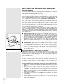
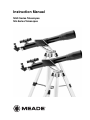
Fig. 15: Celestial Sphere.
A celestial coordinate system was created that maps an imaginary sphere surrounding the
Earth upon which all stars appear to be placed. This mapping system is similar to the system of latitude and longitude on Earth surface maps.
In mapping the surface of the Earth, lines of longitude are drawn between the North and
South Poles and lines of latitude are drawn in an East-West direction, parallel to the Earth’s
equator. Similarly, imaginary lines have been drawn to form a latitude and longitude grid
for the celestial sphere. These lines are known as Declination and Right Ascension.
The celestial map also contains two poles and an equator just like a map of the Earth. The
poles of this coordinate system are defined as those two points where the Earth’s North
and South poles (i.e., the Earth's axis), if extended to infinity, would cross the celestial
sphere. Thus, the North Celestial Pole (1, Fig. 15) is that point in the sky where an extension of the North Pole intersects the celestial sphere. The North Star, Polaris, is located
very near the North Celestial Pole (1, Fig. 15). The celestial equator (2, Fig. 15) is a projection of the Earth’s equator onto the celestial sphere.
So just as an object's position on the Earth’s surface can be located by its latitude and longitude, celestial objects may also be located using Right Ascension and Declination. For
example: You could locate Los Angeles, California, by its latitude (+34°) and longitude
(118°). Similarly, you could locate the Ring Nebula (M57) by its Right Ascension (18hr) and
its Declination (+33°).
■ Right Ascension (R.A.): This celestial version of longitude is measured in units of
hours (hr), minutes (min) and seconds (sec) on a 24-hour "clock" (similar to how
Earth's time zones are determined by longitude lines). The "zero" line was arbitrarily
chosen to pass through the constellation Pegasus, a sort of cosmic Greenwich meridian. R.A. coordinates range from 0hr 0min 0sec to 23hr 59min 59sec. There are 24
primary lines of R.A., located at 15-degree intervals along the celestial equator.
Objects located further and further East of the zero R.A. grid line (0hr 0min 0sec) carry
higher R.A. coordinates.
■ Declination (Dec.): This celestial version of latitude is measured in degrees, arc-minutes, and arc-seconds (e.g., 15° 27' 33"). Dec. locations North of the celestial equator are indicated with a plus (+) sign (e.g., the Dec. of the North celestial pole is +90°).
Dec. locations South of the celestial equator are indicated with a minus (–) sign (e.g.,
the Dec. of the South celestial pole is –90°). Any point on the celestial equator (such
as the the constellations of Orion, Virgo, and Aquarius) is said to have a Declination
of zero, shown as 0° 0' 0."
Entering Coordinates for Objects not in the Database
Although your computer control panel contains a database of more than 1400 celestial
objects (stars, nebulae, planets, etc.) that you can observe, you may eventually want to
view objects that are not part of the database. The computer control panel provides a feature that allows you to enter an object's R.A and Dec. coordinates in the "User: Objects"
option of the Object menu.
In order to use this menu option, you first need to look up the R.A and Dec. coordinates of
the object or objects you wish to observe. Check your local library, computer store, bookstore, CD Roms, Internet, or magazines (such as Sky & Telescope or Astronomy), to find
coordinates of celestial objects. The objects/coordinates you enter become part of your
own permanent database, called "User Objects."
To enter coordinates of an object into the "User: Objects" option of the Object menu:
1. Make sure the computer control panel has been initialized and the telescope has been
aligned.
2. After the telescope is aligned, "Select Item: Object" displays. (If necessary, use
UP/DOWN to scroll through the menus, as previously described, to find this option.)
Press ENTER.
3. "Object: Solar System" displays. Keep pressing UP/DOWN until "Object: User Object"
displays and press ENTER.
4. "User Object: Select" displays. Press UP/DOWN until "User Object: Add" displays.
Press ENTER.
5. "Name" displays on the top line and a blinking cursor on the second line. Use
UP/DOWN and ENTER, as previously described, to enter the name of the object you
wish to add to the database.
22
6.
7.
8.
9.
"Right Asc.: 00.00.0" displays. Use UP/DOWN and ENTER to enter the digits for the
Right Ascension coordinate of your object.
"Declination: +00°.00'" displays. Use UP/DOWN and ENTER to enter the digits for the
Declination coordinate of your object. If necessary, use UP/DOWN to change "+" to "."
The computer control panel then prompts you to enter the size of the object. This step
is optional. Use UP/DOWN and ENTER to enter the size (in arc-minutes), if so
desired, and press ENTER to go to the next display. If you do not wish to enter this
information, simply press ENTER.
The computer control panel then prompts you to enter the magnitude of the object. This
step is also optional. Use UP/DOWN and ENTER to enter this information, if so desired,
and press ENTER to go to the next display. "User Object: Add" displays again.
To Go To a user-entered object:
In this procedure, you will choose an object from the User Object list and locate the object.
1. With "User Object: Add" displayed, press UP/DOWN until "User Object: Select" displays. Press ENTER.
2. Use UP/DOWN (if necessary) to scroll to the desired object. Press ENTER.
3. The name of the object and the Right Ascension and Declination coordinates display.
Press ENTER. The displacement numbers for the object display.
4. Use the displacement numbers as previously described (see page 12) to locate the
object.
Landmarks
This menu option allows you to define and store terrestrial objects in the Landmark database. First, a landmark needs to be stored in memory using the "Landmark: Add" option.
To view a landmark, use the "Landmark: Select" option. Landmarks may also be viewed
using the "Landmark Survey" option in the Utilities menu.
To Add a landmark to the database:
In this procedure, you will store the location of terrestrial landmarks in memory.
1. Set the telescope in the home position, if necessary. Note for future reference where the
telescope is located.
2. Select the "Select Item: Setup" menu.
3. Press UP/DOWN until "Select Item: Object" displays. Press ENTER. "Object: Solar
System" displays.
4. Press UP/DOWN until "Object: Landmarks" displays. Press ENTER. "Landmark:
Select" displays.
5. Press UP/DOWN until "Landmark: Add" displays. Press ENTER.
6. "Landmark Name" displays. Using UP/DOWN and ENTER, enter a name for the landmark you wish to add to the database.
7. "Center Landmark. Press Enter" displays. Move the optical tube to the desired landmark and center the object in the eyepiece. Press ENTER. The object is now stored
in memory.
8. "Landmark: Add" displays. If you wish to add more landmarks, repeat steps 5 through
7.
To Select a landmark from the database:
1. Make sure the telescope is located exactly as when the desired landmark was entered
into memory.
2. Display the "Landmark: Select" menu option. Press ENTER.
3. Use UP/DOWN to scroll through the list of objects you have previously entered. When
the desired object displays, press ENTER to select the object.
Press ENTER to display the displacement numbers for the landmark. Use the displacement numbers as previously described (see page 12) to locate the object.
4. Press MODE and then use UP/DOWN to scroll through location information about the
object (that you have previously entered), if desired.
5. Press MODE again to exit the Landmark menu.
23
APPENDIX B: ALTERNATE TRAY ASSEMBLY
Leg brace
Introduction
Some NGC/NG models are now shipped with a third style tray. The third style assembles with a round accessory tray.
Assembly
Leg brace support
•
Use the provided 3 short screws, 3 washers and 3 bolts to attach the round
accessory tray to the tripod. You will need a Phillips-head screwdriver to perform
this assembly.
•
Line up one of the leg braces (see Fig. 16) between the opening of one of the tripod leg brace supports on the tripod so that a screw will be able to pass through
both the holes of the leg brace support and holes of the leg brace.
Using a Phillips-head screwdriver, thread one of the short screws through the
holes. Place a washer on the other end, followed by the matching nut. Tighten to
a firm feel. Repeat this procedure until all 3 leg braces are mounted on the 3 leg
brace supports. See Fig. 16.
Fig. 16: Attach the leg
braces to the leg brace
supports.
•
Mounting
bolt hole
To attach the accessory tray to the leg braces, place the round accessory tray
over the mounting bolt hole (Fig. 17). Thread the attachment knob into the the
mounting hole on top of the tray (Fig. 17) and turn the knob clockwise (Fig. 18).
Tighten to a firm feel, but do not overtighten—you will need to remove the tray if
you wish to collapse the tripod. To remove the tray, just rotate the knob counterclockwise and remove the knob. You can then lift and remove the tray.
Fig. 17: Mounting bolt hole.
TIPS for Beginners
Further Study
Below is a small sampling of books, magazines, and organizations that you might find
helpful.
Books
1.
The Guide to Amateur Astronomy by Jack Newton and Philip Teece
2.
The Sky: A User’s Guide by David Levy
3.
Turn Left at Orion by Guy Consolmagno and Dan Davis
4.
Astrophotography for the Amateur by Michael Covington
Magazines
1.
2.
Fig. 18: Place tray onto the
mounting bolt hole and
thread the attachment knob
into place.
Sky & Telescope
Box 9111, Belmont, MA 02178
Astronomy
Box 1612, Waukesha, WI 53187
Organizations:
1.
2.
3.
Astronomical League
Executive Secretary
5675 Real del Norte, Las Cruces, NM 88012
The Astronomical Society of the Pacific
390 Ashton Ave, San Francisco, CA 94112
The Planetary Society
65 North Catalina Ave, Pasadena, CA 91106
And watch Jack Horkheimer, Star Gazer, on your local PBS station.
24
BASIC ASTRONOMY
In the early 17th century, Italian scientist Galileo, using a crude telescope smaller than
your NG or NGC, turned it to look towards the sky instead of distant trees and mountains. What he saw, and what he realized about what he saw, forever changed the
way mankind thought of the universe. Imagine what it must have been like being the
first human to see moons revolve around the planet Jupiter or to see the changing
phases of Venus! Because of his observations, Galileo correctly realized Earth's
movement and position around the Sun, and in doing so, gave birth to modern astronomy. Yet Galileo's telescope was so crude, he could not clearly make out the rings of
Saturn.
Galileo's discoveries laid the foundation for understanding the motion and nature of
the planets, stars and galaxies. Building on his foundation, Henrietta Leavitt determined how to measure the distance to stars; Edwin Hubble proposed a glimpse into
the origin of the universe; Albert Einstein unraveled the relationship of time and light.
Almost daily, using sophisticated successors to Galileo's crude telescope, such as the
Hubble Space Telescope and the Chandra X-Ray telescope, more and more mysteries of the universe are being solved and understood. We are living in the golden age
of astronomy.
Unlike other sciences, astronomy welcomes contributions from amateurs. Much of the
knowledge we have on subjects such as comets, meteor showers, variable stars, the
Moon and our solar system comes from observations made by amateur astronomers.
So as you look through your telescope, keep in mind Galileo. To him, a telescope was
not a mere machine of glass and metal, but something far more—a window of incredible discovery.
The Glossary
Be sure to make use of the Glossary feature in your NGC computer control panel. The
Glossary menu provides an alphabetical listing of definitions and descriptions of common astronomical terms. Access directly through the Glossary menu or through
hypertext words. See GLOSSARY MENU, page 17, for more information.
Objects in Space
Listed below are some of the many astronomical objects that can be seen with your
telescope:
The Moon
The Moon is, on average, a distance of 239,000 miles (380,000km) from Earth and is
best observed during its crescent or half phase when Sunlight strikes the Moon’s surface at an angle. It casts shadows and adds a sense of depth to the view (Fig. 19).
No shadows are seen during a full Moon, causing the overly bright Moon to appear
flat and rather uninteresting through the telescope. Try using a neutral Moon filter
when observing the Moon. Not only does it protect your eyes from the bright glare of
the Moon, but it also helps enhance contrast, providing a more dramatic image.
Brilliant detail can be observed on the Moon, including hundreds of lunar craters and
maria, described below.
Fig. 19: The Moon. Note the deep
shadows in the craters.
Craters are round meteor impact sites covering most of the Moon’s surface. With no
atmosphere on the Moon, no weather conditions exist, so the only erosive force is
meteor strikes. Under these conditions, lunar craters can last for millions of years.
Maria (plural for mare) are smooth, dark areas scattered across the lunar surface.
These dark areas are large ancient impact basins that were filled with lava from the
interior of the Moon due to the depth and force of a meteor or comet impact.
Twelve Apollo astronauts left their bootprints on the Moon in the late 1960's and early
1970's. However, no telescope on Earth is able to see these footprints or any other
artifacts. In fact, the smallest lunar features that may be seen with the largest telescope on Earth are about one-half mile across.
Planets
Planets change positions in the sky as they orbit around the Sun. To locate the planets on a given day or month, consult a monthly astronomy magazine, such as Sky
25
and Telescope or Astronomy. Listed below are the best planets for viewing through
your telescope.
Venus is about nine-tenths the diameter of Earth. As Venus orbits the Sun, observers
can see it go through phases (crescent, half and full) much like those of the Moon.
The disk of Venus appears white as Sunlight is reflected off the thick cloud cover that
completely obscures any surface detail.
Mars is about half the diameter of Earth, and appears through the telescope as a tiny
reddish-orange disk. It may be possible to see a hint of white at one of the planet’s
Polar ice caps. Approximately every two years, when Mars is closest to Earth in its
orbit, additional detail and coloring on the planet's surface may be visible.
Fig. 20: Jupiter and its four largest
moons. The moons can be observed in
a different position every night.
Jupiter is the largest planet in our solar system and is 11 times the diameter of Earth.
The planet appears as a disk with dark lines stretching across the surface. These
lines are cloud bands in the atmosphere. Four of Jupiter’s 39 moons (Io, Europa,
Ganymede, and Callisto) can be seen as "star-like" points of light when using even
the lowest magnification (Fig. 20). These moons orbit Jupiter so that the number of
moons visible on any given night changes as they circle around the giant planet.
Saturn is nine times the diameter of Earth and appears as a small, round disk with
rings extending out from either side (Fig. 21). In 1610, Galileo, the first person to
observe Saturn through a telescope, did not understand that what he was seeing
were rings. Instead, he believed that Saturn had "ears." Saturn’s rings are composed
of billions of ice particles ranging in size from a speck of dust to the size of a house.
Titan, the largest of Saturn’s 30 moons can also be seen as a bright, star-like object
near the planet.
Deep-Sky Objects
Star charts can be used to locate constellations, individual stars and deep-sky
objects. Examples of various deep-sky objects are given below:
Fig. 21: Saturn has the most extensive
ring structure in our Solar System.
Stars are large gaseous objects that are self-illuminated by nuclear fusion in their
core. Because of their vast distances from our solar system, all stars appear as pinpoints of light, irrespective of the size of the telescope used.
Nebulae are vast interstellar clouds of gas and dust where stars are formed. Most
impressive of these is the Great Nebula in Orion (M42), a diffuse nebula that appears
as a faint wispy gray cloud. M42 is 1600 light years from Earth.
Open Clusters are loose groupings of young stars, all recently formed from the same
diffuse nebula. The Pleiades is an open cluster 410 light years away (Fig. 22).
Numerous stars are visible.
Constellations are large, imaginary patterns of stars believed by ancient civilizations
to be the celestial equivalent of objects, animals, people or gods. These patterns are
too large to be seen through a telescope. To learn the constellations, start with an
easy grouping of stars, such as the Big Dipper in Ursa Major. Then, use a star chart
to explore across the sky.
Fig. 22: The Pleiades is one of the
most beautiful open clusters.
26
Galaxies are large assemblies of stars, nebulae and star clusters that are bound by
gravity. The most common shape is spiral (such as our own Milky Way), but galaxies
can also be elliptical, or even irregular blobs. The Andromeda Galaxy (M31) is the
closest spiral-type galaxy to our own. This galaxy appears fuzzy and cigar-shaped. It
is 2.2 million light years away in the constellation Andromeda, located between the
large "W" of Cassiopeia and the great square of Pegasus.
MEADE LIMITED WARRANTY
Every Meade telescope, spotting scope, and telescope accessory is warranted by Meade Instruments Corporation ("Meade")
to be free of defects in materials and workmanship for a period of ONE YEAR from the date of original purchase in the U.S.A.
and Canada. Meade will repair or replace a product, or part thereof, found by Meade to be defective, provided the defective
part is returned to Meade, freight-prepaid, with proof of purchase. This warranty applies to the original purchaser only and is
non-transferable. Meade products purchased outside North America are not included in this warranty, but are covered under
separate warranties issued by Meade international distributors.
RGA Number Required: Prior to the return of any product or part, a Return Goods Authorization (RGA) number must be
obtained from Meade by writing, or by calling (949) 451-1450. Each returned part or product must include a written statement
detailing the nature of the claimed defect, as well as the owner’s name, address, and phone number.
This warranty is not valid in cases where the product has been abused or mishandled, where unauthorized repairs have been
attempted or performed, or where depreciation of the product is due to normal wear-and-tear. Meade specifically disclaims
special, indirect, or consequential damages or lost profit which may result from a breach of this warranty. Any implied warranties which cannot be disclaimed are hereby limited to a term of one year from the date of original retail purchase.
This warranty gives you specific rights. You may have other rights which vary from state to state.
Meade reserves the right to change product specifications or to discontinue products without notice.
14-0060-00 6/04B