1
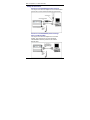
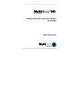
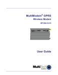
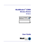
MultiConnect ™ BT
Serial-to-Bluetooth® Adapter
Quick Start Guide
Copyright and Technical Support
MultiConnect BT
Serial-to-Bluetooth Adapter
MTS2BTA and MTS2BTA-R
Quick Start Guide
82010051L Rev. B
Copyright © 2005-2007 by Multi-Tech Systems, Inc. All rights reserved. This
publication may not be reproduced, in whole or in part, without prior written
permission from Multi-Tech Systems, Inc. Multi-Tech Systems, Inc. makes no
representations or warranty with respect to the contents hereof and specifically
disclaims any implied warranties of merchantability or fitness for any particular
purpose. Furthermore, Multi-Tech Systems, Inc. reserves the right to revise this
publication and to make changes from time to time in the content hereof without
obligation of Multi-Tech Systems, Inc. to notify any person or organization of such
revisions or changes.
Revision
A
B
Date
05/09/05
12/10/07
Description
Initial release.
Updated for Bluetooth protocol 2.0. Added more
explanation of the MTS2BTA-R source of power.
Trademarks
Multi-Tech and the Multi-Tech logo are registered trademarks of Multi-Tech
Systems, Inc. MultiConnect is a trademark of Multi-Tech Systems, Inc. Bluetooth
is a registered trademark of Bluetooth SIG, Inc. All other brand and product names
mentioned in this publication are trademarks or registered trademarks of their
respective companies.
World Headquarters
Multi-Tech Systems, Inc.
2205 Woodale Drive
Mounds View, Minnesota 55112 U.S.A.
(763) 785-3500 or (800) 328-9717
U.S. Fax (763) 785-9874
www.multitech.com
Technical Support
Country
Email
Europe, Middle East, Africa [email protected]
U.S., Canada, all others
[email protected]
2
Phone
+44 118 959 7774
800-972-2439 or
763-717-5863
Serial-to-Bluetooth Adapter
Introduction
This guide shows you how to set up your MultiConnect Adapter. For
detailed information, product specifications, and more, see the User
Guide, available on the MultiConnect CD and the Multi-Tech Web site.
General Safety
The modem is designed for and intended to be used in fixed and mobile
applications.
Caution: Maintain a separation distance of at least 20 cm (8 inches)
between the transmitter’s antenna and the body of the user or nearby
persons. The modem is not designed for, nor intended to be, used in
applications within 20 cm (8 inches) of the body of the user.
Radio Frequency Interference
Avoid possible radio frequency (RF) interference by carefully following
the safety guidelines below.
• Switch OFF the MultiModem when in an aircraft. The use of cellular
telephones in aircraft is illegal. It may endanger the operation of the
aircraft and/or disrupt the cellular network. Failure to observe this
instruction may lead to suspension or denial of cellular services to
the offender, legal action, or both.
• Switch OFF the MultiModem in the vicinity of gasoline or diesel-fuel
pumps or before filling a vehicle with fuel.
• Switch OFF the MultiModem in hospitals and any other place where
medical equipment may be in use.
• Respect restrictions on the use of radio equipment in fuel depots,
chemical plants, or in areas of blasting operations.
• There may be a hazard associated with the operation of your
MultiModem in the vicinity of inadequately protected personal
medical devices such as hearing aids and pacemakers. Consult the
manufacturers of the medical device to determine if it is adequately
protected.
• Operation of the MultiModem in the vicinity of other electronic
equipment may cause interference if the equipment is inadequately
protected. Observe any warning signs and manufacturers’
recommendations.
3
Multi-Tech Systems, Inc. Quick Start Guide
Vehicle Safety
• Do not use your Wireless MultiModem while driving, unless
equipped with a correctly installed vehicle kit allowing ‘Hands-Free’
Operation.
• Respect national regulations on the use of cellular telephones in
vehicles. Road safety always comes first.
• If incorrectly installed in a vehicle, the operation of wireless
MultiModem telephone could interfere with the correct functioning
of vehicle electronics. To avoid such problems, be sure that
qualified personnel have performed the installation. Verification of
the protection of vehicle electronics should be part of the
installation.
• The use of an alert device to operate a vehicle’s lights or horn on
public roads is not permitted.
Package Contents
MTS2BTA (Externally Powered)
• One Serial-to-Bluetooth Adapter
• One antenna
• One mounting bracket
• One power supply
• A set of four self-adhesive plastic feet
• One printed Quick Start Guide
• One MultiConnect CD containing the adapter drivers, User Guide,
Quick Start Guide, AT Commands Reference Guide, Global Wizard
software, and link to Adobe Web site for Acrobat Reader.
MTS2BTA-R (Powered by Pin 6 of an RS-232 Cable)
• One Serial-to-Bluetooth Adapter
• One antenna
• One mounting bracket
• A set of four self-adhesive plastic feet
• One printed Quick Start Guide
• One MultiConnect CD containing the adapter drivers, User Guide,
Quick Start Guide, AT Commands Reference Guide, Global Wizard
software, and link to Adobe Web site for Acrobat Reader.
4
Serial-to-Bluetooth Adapter
Installation and Cabling
Attaching the MultiConnect Adapter to a Fixed Location
1. Typically, the MultiConnect is mounted against a flat
surface with two mounting screws. Drill the mounting
holes at the desired mounting location. The mounting
holes must be separated by 4-15/16 inches center-tocenter.
2.
To attach the mounting bracket, slide it into the
corresponding slot on the back of the MultiConnect
chassis.
3.
Attach the adapter to the surface with two screws.
5
Multi-Tech Systems, Inc. Quick Start Guide
Making the Connections
Directions for the MTS2BTA (Externally Powered)
Turn off your PC. Place the adapter in a convenient location.
Connect it to your PC’s serial port and plug in the power.
Directions for the MTS2BTA-R (Powered through
Pin 6 of an RS-232 Cable)
Turn off your PC. Place the adapter in a convenient
location. Then connect it to your PC’s serial port.
The MTS2BT-R draws its power from Pin 6 of the
RS-232 cable.
6
Serial-to-Bluetooth Adapter
Optional – Directions for Direct DC Power
Connection for Use with the MTS2BTA
•
Connect a fused DC power
cable into the power
connector on the
MultiModem.
•
Then attach the two wires
at the other end of the
fused cable to a DC
fuse/terminal block on a
vehicle in which you are
mounting the MultiModem.
Connect the red wire to the
"+" positive and the black
wire to the "–" negative. Be
sure the GND connection is
correct.
Note: For automotive
application: according to the
type of application, you can
use permanent “+” or keyswitched “+”. Connect the
power supply to its source (for
example, in a mobile situation,
to the vehicle’s DC
fuse/terminal block).
Warning: Over-voltage
protection is provided on the
device. To ensure complete
protection, you may want to
add additional filtering to the
DC input.
7
Multi-Tech Systems, Inc. Quick Start Guide
Using AT Commands to Set Parameters
Parameters, such as the Bluetooth Name, Service Name, Device Class,
and Serial Port settings can be viewed and configured. This can be done
locally through the serial port UART or from a remote Bluetooth RF link.
To configure the Bluetooth adapter, it must be in command mode; issue
the +++ command to switch to command mode. While in command
mode, the adapter will accept ASCII bytes as commands.
The communications settings should match the settings used when the
Bluetooth adapter connects. For example, the defaults are:
9600bps, 8 bits, no parity, 1 stop bit, hardware flow control enabled.
Master Discovery/Connection Sequence Example:
From Power Up and No Connection
1. Verify Local Device is Master in Data Mode.
Sent: ATSi,7 <cr>
Reply: <cr_lf>1,1,0,0<cr_lf>
2. If not Master, Set to Master and Data Mode.
Sent: ATSW25,1,1,0,0 <cr>
Reply: <cr_lf>OK<cr_lf>
3. Perform Inquiry to Obtain BT_Addresses (when not known).
Sent: ATUCL
// Clears radio state
Reply: <cr_lf>OK<cr_lf>
Sent: ATDI,1,00000000 {Class of Device}<cr>
// Looks for only one Bluetooth device
Reply: cr_lf>00A0961F2023,00000104,MTS2BTA
<cr_lf>DONE<cr_lf>CONNECT <cr_lf>
4. Perform a Master Connect over SPP Using the BT_Address.
Sent: ATDM, 00A0961F2023,1101<cr> // SPP connection
Reply: <cr_lf>CONNECT,00A0961F008F cr_lf> // Returns
Slave BT address; radio is in data mode
8
Serial-to-Bluetooth Adapter
5.
Place radio into Fast Data Mode.
Sent: +++<cr>
// Places radio in Command Mode
Reply: <cr_lf>OK<cr_lf>
Sent: ATMF<cr> // Places radio in Fast Data Mode
Reply: <cr_lf>OK<cr_lf>
6.
Send Data.
Note: Sending commands from the slave when the slave
connects in Fast Data Mode (ATSW25/ or issue ATMF):
All valid AT commands sent through the Slave's UART will be
interpreted and responded by the Master as if it were the local
Slave radio. Basically, in this configuration from the Slave end,
you can obtain status and configure the remote Master radio.
This is a unique feature that may be useful in some
applications, but it can be confusing if you think you are talking
to the Slave.
To Get Out of Data Mode and Check Status
1.
2.
3.
4.
Delay at least 50 milliseconds; this could be less or more.
Perform a Set Command Mode.
Sent: +++<cr>
Reply: <cr_lf>OK<cr_lf>
Delay at least 50 milliseconds.
Check Status, perform a Disconnect …
Sent: AT<cr>
Reply: <cr_lf>OK<cr_lf>
Note about being connected in Fast Data Mode
If connected in Fast Data Mode, it is necessary to reset the
Master or Slave to break the connection.
9
Multi-Tech Systems, Inc. Quick Start Guide
Slave Command Sequence Example
From Power Up:
1. Check and verify Communication to Slave.
Sent: AT<cr>
Reply: <cr_lf>OK<cr_lf>
2. Get information on Slave Bluetooth address.
Sent: ATSi,1<cr>
Reply: 12-digit address
<cr_lf>OK<cr_lf>
3. Set Slave to automatically connect in Fast Data Mode on
Bluetooth connection.
Sent: ATSW25,0,0,0,0 <cr>
Reply: <cr_lf>OK<cr_lf>
Either cycle power or send ATURST.
Note: This command sequence assumes the radio is set to
factory defaults that allow it to automatically come up and be
ready to connect as a Slave from a Master request.
10
82010051L