1
GoodKnight® 425
GoodKnight® 425ST
SERVICE MANUAL
P/N: M-145MAT00-20
Revision A
GoodKnight 425 / 425ST
Service Manual
This document is the property of NELLCOR PURITAN BENNETT, Inc and is distributed on the express condition that
it is neither divulged nor reproduced in part or in full by anyone other than NELLCOR PURITAN BENNETT, Inc without prior written agreement, and no right is granted to divulge or use any information contained in this document.
ã
Copyright NELLCOR PURITAN BENNETT, Inc - 2004
ALL RIGHTS RESERVED
P/N: M-145MAT00-20 Rev. A - Page Rev.A
1
GoodKnight 425 / 425ST
Service Manual
PREFACE
This manual provides information necessary to service the GoodKnight 425 and the GoodKnight
425ST Respiratory System. This information is intended for use by technicians or personnel qualified to repair and service medical equipment. The information is not exhaustive and may not be applicable to future models.
DEFINITION OF STATEMENTS
Statements in this manual preceded by the followings words are of special significance.
WARNING
Means there is the possibility of injury or death to yourself or others.
CAUTION
Means there is the possibility of damage to the GK 425/425ST unit or other property.
NOTE
Indicates points of particular interest for more efficient and convenient operation.
P/N: M-145MAT00-20 Rev. A - Page Rev.A
2
GoodKnight 425 / 425ST
Service Manual
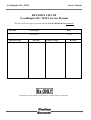
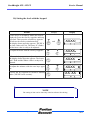
REVISION LIST OF
GoodKnight 425 / 425ST Service Manual
This list of effective pages represents manual P/N M-145MAT00-20, revision A.
Revision
Description
Date
A
Initial Release.
05/2004
Effective Pages
All pages
Revision
Effective Pages
Revision
A
Federal law restricts this device for sale by or on the order of a physician.
P/N: M-145MAT00-20 Rev. A - Page Rev.A
3
GoodKnight 425 / 425ST
Service Manual
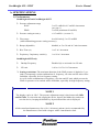
CONTENTS
PREFACE
2
REVISION LIST
3
I - GENERAL INFORMATION
A. SPECIFICATIONS
1)
2)
3)
4)
5)
6)
Performances
Electrical specifications
Environmental specifications
Physical specifications
Pressure stability
Dynamic resistance
I-1
I-2
I-2
I-2
I-3
I-3
I-3
I-4
B. USING A HUMIDIFIER
I-4
C. SYMBOLS
I-5
D. CLEANING INSTRUCTIONS
I-6
I-6
I-6
1) GoodKnight 425 / 425ST
2) Air filter
E. DISPOSAL OF THE DEVICE AT THE END OF ITS LIFETIME
I-6
II - THEORY OF OPERATION
II-1
A. GENERAL DESCRIPTION
II-2
II-2
II-2
II-3
II-3
II-4
II-4
II-4
1)
2)
3)
4)
5)
6)
7)
General design synopsis
View of the control panel
Description
Inspiratory/Expiratory sensitivity
Temperature Sensor
Rise Time
Pneumatic Diagram
P/N: M-145MAT00-20 Rev. A - Page Rev.A
4
GoodKnight 425 / 425ST
B. ELETRICAL DIAGRAM
1)
2)
3)
4)
5)
6)
General Block diagram
Micro-controller
Pressure measurement chain block diagram
Flow measurement chain block diagram
Temperature measurement
Serial Link
III - SERVICE AND REPAIR
A. PERFORMANCE VERIFICATION
1)
2)
3)
4)
5)
6)
7)
8)
9)
10)
General information
Frequency
Equipment required
Preparation for testing
Verification with computer
5-a) Preparation
5-b) Pressure verification and calibration
5-c) Verification of the Flow measurement chain
5-d) Verification of the ramp
5-e) Verification of the backup frequency (425ST only)
Performance Verification with keypad
6-a) Verification of the pressure without computer
6-b) Ramp verification
6-c) Verification of the backup frequency (425ST only)
Configuration with factory settings
Entering the serial number and hour meter values
“Service” hour meters
Setting the Clock with keypad
B. CALIBRATION PROCEDURE
1) Equipment required
2) Pressure sensor calibration
3) Flow sensor calibration
Service Manual
II-5
II-5
II-6
II-7
II-7
II-8
II-8
III-1
III-3
III-3
III-3
III-3
III-4
III-5
III-7
III-7
III-8
III-9
III-9
III-10
III-10
III-12
III-13
III-14
III-15
III-15
III-16
III-18
III-18
III-19
III-20
C. DISASSEMBLY
III-22
D. TROUBLESHOOTING GUIDE
III-20
III-21
Information Messages
E. ERROR MESSAGES
III-26
¨ HISTORY RECORD FORM
III-27
IV - SPARE PARTS
P/N: M-145MAT00-20 Rev. A - Page Rev.A
IV-1
5
GoodKnight 425 / 425ST
P/N: M-145MAT00-20 Rev. A - Page Rev.A
Service Manual
6
GoodKnight 425 / 425ST
Service Manual
I - GENERAL INFORMATION
P/N: M-145MAT00-20 Rev. A - Page Rev. A
I-1
GoodKnight 425 / 425ST
Service Manual
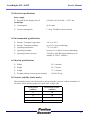
A. SPECIFICATIONS
1) Performances
GoodKnight 425 and GoodKnight 425ST
Ä Pressure adjustment range
IPAP:
3 to 25 cmH2O in 0.5 cmH2O increments
(see note 1)
3 to PIP (maximum 20 cmH2O)
EPAP:
Ä Pressure setting accuracy:
± 0.5 cmH2O (see note 2)
Ä Flow range
0 to 90 l/min @ 3 to 25 cmH2O
(while maintaining pressure setting accuracy)
Ä Ramp (adjustable)
disabled, or 5 to 30 min in 5 min increments
Ä Rise Time (rt)
1 to 5 in 1 increment
Ä Expiratory / Inspiratory sensitiviy
1 to 10 in 1 increment
GoodKnight 425ST only
Ä
Backup Frequency
Disabled (0) or activated 4 to 25c/min
Ä
I/E ratio
1:4.0 to 1:0.5 in 1:0.5 increment
Ä Setting restrictions: The maximum duration of the IPAP pressure is limited to 3 seconds. Consequently certain combinations of frequency, rise time and I/E ratio will be
forbidden, especially for low frequency setting.
As well, certain combinations of frequency, rise time and I/E ratio which prevent the
IPAP set pressure to be reached will be forbidden, especially for high frequency setting.
NOTE 1
The display can be in “hPa”. The pressure adjustment range is then between 2.9 hPa
and 24.5 hPa. To select the unit, unplug the device, depress the hidden key and reconnect the device, keeping the hidden key depressed until the unit is displayed.
NOTE 2
All the stated performances are for a 6 ft (1.80-meter) patient circuit, recommended by
the manufacturer, fitted with a stopper with a 4 mm diameter leak.
P/N: M-145MAT00-20 Rev. A - Page Rev. A
I-2
GoodKnight 425 / 425ST
Service Manual
2) Electrical specifications
Power supply
Ä External Power Supply Class II
100-240 VAC 50/60 Hz—13VCC 4A
Goodknight
Ä Consumption
40 VA max.
Ä Current consumption
1.1A @ 25cmH2O with 4 mm leak
3) Environmental specifications
Ä Storage / Transport temperature
-20° C to 60° C
Ä Storage / Transport humidity
up to 95 % (non-condensing)
Ä Operating temperature
+5° C to +40° C
Ä Operating humidity
between 15 % and 95 % (non-condensing)
Ä Operating relative pressure
700 hPa to 1060 hPa (approximately up to
altitude of 7874 ft -2.400 m)
4) Physical specifications
Ä Width
5.6” (144 mm)
Ä Height
2.9” (79 mm)
Ä Length
7.7” (198 mm)
Ä Weight (without external power module)
1.58 lbs (780 g)
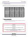
5) Pressure stability (static mode)
The measured pressures are the pressures measured under a positive airflow continuous of
100 l/min. These measurements were made with a single unit.
Set Pressure
(cmH2O)
Measured Pressure
(cmH2O)
4
3.8
8
7.8
12
11.7
20
19.9
P/N: M-145MAT00-20 Rev. A - Page Rev. A
I-3
GoodKnight 425 / 425ST
Service Manual
6) Dynamic resistance
The values below were measured from a simulated sinusoidal respiratory signal with a tidal volume
of 500 ml after a warm-up period of 2 hours. These measurements were made with a single unit.
Pressure @ Frequency
Variation in pressure
(CmH2O)
Variation in airflow
(l/s)
Dynamic resistance
(CmH2O/l/s)
7cmH2O @ 10c/min
0,28
0,66
0,42
7cmH2O @ 15c/min
0,37
0,98
0,38
7cmH2O @ 20c/min
0,58
1,28
0,45
14cmH2O @ 10c/min
0,38
0,70
0,54
14cmH2O @ 15c/min
0,43
1,03
0,42
14cmH2O @ 20c/min
0,64
1,33
0,48
20cmH2O @ 10c/min
0,58
0,88
0,58
20cmH2O @ 15c/min
0,50
1,07
0,47
20cmH2O @ 20c/min
0,64
1,26
0,51
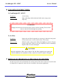
B. USING A HUMIDIFIER
A heating or non-heating humidifier may be used with the GoodKnight 425 / 425ST on the
condition that the following warnings are noted.
WARNING
You are strongly advised to read the manufacturer’s recommendations for the humidifier before use.
WARNING
Using a humidifier can alter the performance of the GoodKnight 425 / 425ST.
WARNING
The GoodKnight 425 / 425ST must always be placed above the humidifier. This position
will minimize the potential for water entering the Cpap device.
Water can damage the device.
P/N: M-145MAT00-20 Rev. A - Page Rev. A
I-4
GoodKnight 425 / 425ST
Service Manual
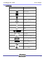
C. SYMBOLS
SYMBOLS
~
DEFINITIONS
Alternating current
Direct current
Class 2 Equipment
Type B
Warning ! Consult instructions
before using this unit.
On / Off
Access to settings
Ramp
RS 232
Increase or decrease the adjustment values
Device protected against the vertical falls of water drops.
Rx ONLY
Federal law restricts this device for
sale by or on the order of a physician. (US Only)
Input DC voltage 13 V
Patient Output
Device complies with the requirements of the Standard CSA C22.2
Nr 601-1. (Canada)
P/N: M-145MAT00-20 Rev. A - Page Rev. A
I-5
GoodKnight 425 / 425ST
Service Manual
D. CLEANING INSTRUCTIONS
1) GoodKnight 425 / 425ST
Frequency
As necessary
How to clean
Wipe with damp cloth moistened with warm, soapy water.
Wipe dry.
WARNING
Unplug the unit from all electrical power sources before cleaning. Do not allow
water to enter the unit through any opening.
2) Air filter
Frequency
Inspect the air filter frequently by removing it from the back panel.
Clean at least once a week or more often, if necessary.
How to clean
Wash in warm, soapy water. Rinse thoroughly to remove all soap.
Pat dry with towel. Allow to air dry completely before reinstalling.
Replace filter if worn or damaged.
CAUTION
Only the standard air filter can be cleaned. The fine filter supplied as an option and
fitted in addition to the standard air filter, cannot be cleaned. It must be changed.
E. DISPOSAL OF THE DEVICE AT THE END OF ITS LIFETIME
In order to preserve the environment, the various parts of the device and its accessories must
be disposed of at approved waste sites in accordance with current regulations.
P/N: M-145MAT00-20 Rev. A - Page Rev. A
I-6
GoodKnight 425 / 425ST
Service Manual
II - THEORY OF OPERATION
P/N: M-145MAT00-20 Rev. A - Page Rev.A
II-1
GoodKnight 425 / 425ST
Service Manual
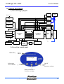
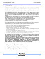
A. General description
1) General design synopsis
Voltage
Main Power
Power AC
AC
Patient
Patient
Interfac
Inte rface
Reference
Flow
nal Module
External
Module
C/DC
AC/DC
Flow
Flow filtered
Flow direct
P
i
t
o
t
Sensor
Pressure
otection
Protection
ltering
Filtering
Pressure filtered
Sensor
Temperature Blower
Current filtered
Regulation
ulation 5V
5V
Current
Alarm Current
Backlight
Measurement
C
T
N
Motor Reset
Type cycle
LCD Module
le LCD
Respiratory phase
Microcontroler
C508
Master
Keypad
ypad
BusyI2CMotor
BusyI2CMaster
ErrorMotor
Serial
al Link
Link
Microcontroler
C508
Motor driver
Power
Driver
Blower
Set Change
Slope
WDI CE
Bus //
OM
ROM
4ko
64K
Current
RAM
64 ko
Reset
Bus I2C
Controler of
NVRAM
Watchdog
Set-up
Battery
RTC +
RAM 56 octets
Air
Input
2) View of the control panel
Hidden Key
LCD Display
Information
Access button
On/Off
or
Parameter settings
Ramp activation or
Parameter settings
P/N: M-145MAT00-20 Rev. A - Page Rev.A
II-2
GoodKnight 425 / 425ST
Service Manual
3) Description
The general architecture of the device is based on the use of a blower (pressurised air generator) and two micro-controllers (one for the general functions of the unit and another one for
the motor control).
Some functions are hardware-controlled, some are software-controlled and others are a mixture of hardware and software.
The GoodKnight 425 BiLevel is a BiLevel positive airway pressure device used in the treatment of obstructive sleep apnea or for the titration in the sleep lab of a patient having obstructive sleep apnea. It is intended to treat OSAS patients who are over 30 kg in weight (66
pounds).
In the BiLevel mode the GoodKnight 425 tracks patient breathing cycles and, in response to
the patient’s inspiratory and expiratory efforts, provides two levels of pressure :
-IPAP : a higher level of pressure for inspiration (a range from EPAP to 25 cmH2O)
-EPAP : a lower pressure for expiration (a range from 3 to IPAP or 20 cmH2O).
-If IPAP is equal EPAP, than the unit operates in CPAP mode.
The GoodKnight 425 BiLevel is a microprocessor-controlled pressure generator capable of
controlling the pressure delivered to the patient. Among its operating features are:
* GK425ST in CPAP, BiLevel with and without backup frequency
* GK425 in CPAP, BiLevel without backup frequency.
* Monitors pressure, respiratory rate, I/E ratio and compliance.
* Adjusts inspiration and exhalation flow-triggered sensitivity independently to provide
precise patient comfort.
* Provides a maximum pressure setting of 25 cmH2O
* Compensates automatically for altitude and for leaks up to a total flow rate of 120 liters
per minute, on top of the usual 4mm non re-breathing leak at 20 cmH2O.
The GoodKnight 420 Series benefits from a new blower technology that is specifically
designed for this range of Cpap systems. This design provides optimum performances in
terms of size, consumption, noise and stability.
In order to guarantee these optimum performances, some parameters are electronically
tuned during the manufacturing process. These parameters are calculated for each
blower and cannot be duplicated for another one. For this reason it is not possible to
change a blower or an electronic board. In the event of failure, an internal chassis assembly fitted with a factory-set blower and electronic board is available.
4) Inspiratory and Expiratory sensitivity
The trigger of sensitivity can be set with a scale of 1 to 10.
1= The lower triggering level = The highest sensitivity,
10=The highest triggering level = The lower sensitivity.
P/N: M-145MAT00-20 Rev. A - Page Rev.A
II-3
GoodKnight 425 / 425ST
Service Manual
5) Temperature Sensor
The stator of the blower is fitted with a temperature sensor which will protect the system
against the overheating of the blower in the eventuality of a problem.
The GoodKnight BiLevel will stop working if the temperature goes above 95°C +/-5°C during
10 seconds.
6) Rise time (rt)
The rise time between EPAP and IPAP can be set from about 300ms/ 10 cmH2O to about
600ms/10 cmH2O. This rise time is adjustable on a scale of 1 to 5:
1 ~ 300ms / 10cmH2O
2 ~ 375ms / 10cmH2O
3 ~ 450ms / 10cmH2O
4 ~ 525ms / 10cmH2O
5 ~ 600ms / 10cmH2O
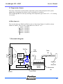
7) Pneumatic diagram
Pitot Tube
Air
Output
connector
Patient
tube
Blower
Impeller
DC Motor
Nasal mask
or
nasal pillows
Flow
Sensor
Electrical system
Inlet filter
P/N: M-145MAT00-20 Rev. A - Page Rev.A
Humidifier
(optional)
Pressure Sensor
Pressure sensor
tube
II-4
GoodKnight 425 / 425ST
Service Manual
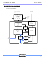
B. ELECTRICAL DIAGRAM
1) General block diagram
1.1.2
1.1.3
Power
Supply
Main
Power
AC AC
Serial Link
External Power Supply
External Module
AC/DC
Isolation
Barrier
4kV
100 – 264 Vac
1.1.1.1
13Vcc / 24W
13Vcc-4A
Interface
Serial Link
Protection
and
Filtrage
Regulation
5V
Electronic
Moteur Driver
Blower
Air
Input
Pitot
tube
Flow
Pressure
Sensor
Sensor
Pressure
Sensor
PATIENT
P/N: M-145MAT00-20 Rev. A - Page Rev.A
Case
Case
GK420
II-5
GoodKnight 425 / 425ST
Service Manual
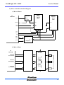
2) Micro-controller unit block diagram
a) Micro-Master
µC
MASTER
Data
Memory
SRAM
64 ko
MAX691
P51
WDI
Reset
CS
Reset
WR
RD
Software
Memory
ROM
64 ko
CS
WE
OE
G
Vcc
A15
A8
AD7
AD0
ALE
A0-7
AD0 – 7
D0 – 7
Multiplexer
b) Micro-Motor
µC
MOTOR
Interfaces
Bridges
MOSFET
Motor
P12/CC0
P13/COUT0
P14/CC1
P15/COUT1
P16/CC2
P17/COUT2
P/N: M-145MAT00-20 Rev. A - Page Rev.A
II-6
GoodKnight 425 / 425ST
Service Manual
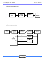
3) Pressure measurement chain
Pressure
Filter RC
Lowpass
Fc = 152 Hz
Sensor
Follower
Patient
Tube
µC
MASTER
and
MOTOR
4) Flow measurement chain
Flow
Sensor
Amplifier
differential
G = 40
P42
µC
MASTER
and
MOTOR
P43
P45
P/N: M-145MAT00-20 Rev. A - Page Rev.A
Offset
Adjustment
Flow
Flow filtered
Gain
Adjustment
Linearity
Filter
Hightpass
fc = 7,23 Hz
Filter
Lowpass
fc = 0,17Hz
Direct Flow
II-7
GoodKnight 425 / 425ST
Service Manual
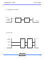
5) Temperature measurement
Blower
Linearity
CTN
Follower
µC Master
6) Serial Link
µC
MASTER
P30/RxD
P31/TxD
P/N: M-145MAT00-20 Rev. A - Page Rev.A
Interface
RS232
Connector
PC
RS232
Tx
Rx
II-8
GoodKnight 425 / 425 ST
Service Manual
III - SERVICE AND REPAIR
P/N: M-145MAT00-20 Rev. A - Page Rev.A
III-1
GoodKnight 425 / 425 ST
Service Manual
This section describes how to service the individual subassembly of the GoodKnight 425
and 425ST Cpap System. It includes instructions where applicable, for removal, disassembly, calibration, re-assembly and installation.
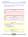
WARNING
The GK 425 and 425ST Cpap System is electrically powered. To prevent serious injury or death, follow standard safety procedures. Ensure that power
has been disconnected from the unit before servicing any component.
WARNING
After a component has been serviced, the unit must be calibrated and the overall
system operation checked according to the “Performance Verification” section,
before the unit is returned to service.
CAUTION
Circuit boards contain complementary metal-oxide semiconductor (CMOS) integrated circuits (ICs) which are static sensitive devices. To prevent IC damage, follow
the standard safety procedures :
-handle circuit boards by edges only,
-wear a grounded wrist strap,
-work on a grounded conductive mat
-store circuit board in a conductive plastic bag.
CAUTION
Allow to warm up for half hour before carrying out the performance verification and/
or the calibration procedure.
P/N: M-145MAT00-20 Rev. A - Page Rev.A
III-2
GoodKnight 425 / 425 ST
Service Manual
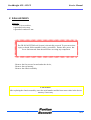
A. PERFORMANCE VERIFICATION
1) General information
The performance verification should be carried out for any one of the following reasons:
to determine the cause of operational failure,
to check the overall operation of the GK 425/425ST system after repair,
to check that the GK 425/425ST system is operating within specification.
·
·
·
During this verification, the following parameters will be tested :
-Pressure accuracy,
-Flow measurement chain
-Ramp and starting ramp pressure,
-Back-up frequency (425ST only).
2) Frequency
annually,
Þ after repair.
Þ
3) Equipment required
·
·
·
·
·
·
Calibrated pressure meter 0-30 cm H2O (local source),
Patient tube P/N : M-261000-27,
Test kit P/N : M-212430-02 (consists of a coupling 22/22 mm and a stopper with a
4 mm diameter leak),
PC computer with Silverlining software,
Serial link cable,
Calibrated leak M-BH0210 and connecting tube M-213530-05.
P/N: M-145MAT00-20 Rev. A - Page Rev.A
III-3
GoodKnight 425 / 425 ST
Service Manual
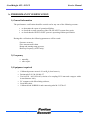
4) Preparation for testing
Pressure meter PTS 2000 P/N: 4-076185-00
a - Verification of the pressure
Coupling
Patient tube M-261000-27
Test Kit
with 4 mm leak
P/N: M-212430-02
(including coupling)
Figure 3-1
b - Verification of the flow measurement chain
Calibrated output M-BH0210
Connecting tube
M-213530-05
Figure 3-2
P/N: M-145MAT00-20 Rev. A - Page Rev.A
III-4
GoodKnight 425 / 425 ST
Service Manual
5) Performance verification with a computer.
CAUTION
Allow to warm up for half hour before carrying out the performance verification and/
or the calibration procedure.
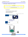
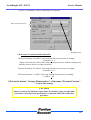
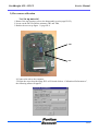
5-a) Preparation
- Set the material as shown on figure 3.1 page III-4
- Connect the GoodKnight 425/425ST to your PC,
- Open the Silverlining 3 software,
- The following menu appears,
Click on "CPAP or BiLevel connection "
- The following display appears,
P/N: M-145MAT00-20 Rev. A - Page Rev.A
III-5
GoodKnight 425 / 425 ST
Service Manual
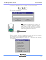
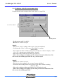
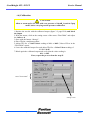
- Press the three following keys of your computer keyboard simultaneously:
Control
Alt
F9
- The following screen appears:
Note: In some case, depending of the computer, the
combination of key (ctrl, alt, F9) does not operates.
In this case press one time on the key « S » and then
with the left button of the mouse click on the picture
of the computer displayed on the screen.
- Enter the password. The password is given to technicians who have been trained by
the manufacturer or a person accredited by the manufacturer.
- After entering the password, press the “Enter” key or click on OK. The following
screen appears :
P/N: M-145MAT00-20 Rev. A - Page Rev.A
III-6
GoodKnight 425 / 425 ST
Service Manual
- Click on “Calibrations” and the following screen appears,
Menu "Pressure/Pression"
{
Setting cursor
5-b) Pressure Verification and Calibration
-Click on the button "14 cmH2O" and verify that the pressure meter is reading:
14 cmH2O + 0,5 .
Adjust if necessary the offset of the menu "Pressure/Pression" with the setting cursor
until the pressure meter is reading 14cmH2O.
-Click on the button "25 cmH2O" and verify that the pressure meter is reading:
25 cmH2O + 0,5 .
-Click on the button "3 cmH2O" and verify that the pressure meter is reading:
3 cmH2O + 0,5 .
Click on the button " Storage/Mémorisation " of the menu "Pressure/Pression"
to store the setting.
CAUTION
Allow to warm up for half hour (Cpap mode; P=14cmH2O; plug test with 4mm
leak) before carrying out the performance verification and/or the calibration
procedure.
P/N: M-145MAT00-20 Rev. A - Page Rev.A
III-7
GoodKnight 425 / 425 ST
Service Manual
5-c) Verification of the flow measurement chain
Prepare the unit under testing as show in the figure 3.2 page III-4
Menu "Flow/Débit"
{
Setting cursor
-Set the pressure with 14 cmH2O,
-BLOCK the calibrated output.
Step #1
-Wait for the “Value” reading on the screen to become stabilized,
-Verify that this “Value” of the menu “Flow/Débit” is reading:
0 l/s (+/- 0.1)
-If not, adjust the Offset with the setting cursor in order to read in the display “Value”
0 l/s +/-0.1, and then store with the button “Storage”.
-If the value read is within specification, go to step #2.
-If the value reading is not within specification, perform the calibration of the
flow sensor described page III-20. Do not go to the step #2
Step #2
-Unblock the calibrated output,
-Wait for the value reading on the screen to become stabilized,
-Check the value reading on the screen in the “Flow/Débit” menu is reading:
1.2 l/s (+/- 0.1)
-If the value reading is within specification, the verification is good.
-If the value reading is not within specification, perform the calibration of the
flow sensor described page III-20.
P/N: M-145MAT00-20 Rev. A - Page Rev.A
III-8
GoodKnight 425 / 425 ST
Service Manual
5-d) Verification of the ramp
Click on the button "Test R" (Test of Ramp). The unit is set with a 5 minutes ramp, start pressure 3 cmH2O , end pressure 20 cmH2O.
Verify that the pressure runs from 3 to 20 cmH2O in the time of::
5 minutes +/- 20 seconds.
5-e) Verification of the back-up frequency (425ST only)
Click on the button "Test F" (Test of Frequency). The unit is set with a frequency of 10 cycles /
min.(IPAP=14; EPAP=8; I/E=1:1.0). Verify that the pressure is switching from EPAP to IPAP
in 10 cycles +/- one cycles per minute.
The performance verification of the unit is now ended.
Click on the EXIT button to leave of the technical menu. The unit will retrieve its previous
settings (settings before the technical action).
NOTE
Some verifications can be performed without a computer (section 6 page III-10). In
order to do them you have to select the corresponding settings with the keypad. (refer
to the sections verification of the pressure, the ramp and the back-up frequency in the
following pages).
The verification of the pressure will not be total (maximum pressure in Cpap mode
=20 cmH2O).
P/N: M-145MAT00-20 Rev. A - Page Rev.A
III-9
GoodKnight 425 / 425 ST
Service Manual
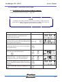
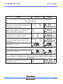
6) Performance verification with Keypad
6-a) Verification of the pressure without computer
Set the material as shown on figure 3.1 page III-4
NOTE
According to the settings limitation it will not be possible to verify the pressure
higher than 20 cmH2O. The pressure verification for 25 cmH2O can be done only
with the computer and the software Silverlining.
Action
Keys(s)
XX: XX
#1-Connect the device on the main power.
XX.XX is the current time.
#2-Press on the two keys opposite and keep them
depressed for 2 seconds. The menu displayed opposite appears (Set frequency).
Display
Hidden Key
XX
#3-Press the opposite key to enter in the setting
of the IPAP pressure.
#4-Select P = 14 cmH2O with the two keys opposite, then press the following key:
#5-Select EPAPA = 14 cmH2O with the two
keys opposite, then press the following key.
#6-Press the opposite key as many times as necessary to return into stand by mode (current time
displayed)
c m H 2O
cm H 2O
XX: XX
#7-Turn on the unit and leave running for 1/2
hour
P/N: M-145MAT00-20 Rev. A - Page Rev.A
III-10
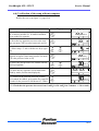
GoodKnight 425 / 425 ST
Action
Service Manual
Key(s)
Display
Check the measured value on the pressure meter, the value must be 14 cmH2O ± 0.5.
If yes, go to point #12
If not, go to point #8
#8-Press on the two keys opposite and keep them
depressed for 2 seconds. The menu displayed opposite appears (Set frequency).
XX
Hidden Key
#9-Press the key opposite several times until the
display opposite appears (mode calibration).
XXX is a value between 0 and 255.
XXX
#10-Adjust the value with the keys opposite until
the pressure meter is reading 14 cmH2O.
XXX
#11-Record the selected value by pressing the
hidden key, keeping it depressed and pressing
the access key..
#12-Go to points #2 to #5 and select
EPAP=IPAP= 20 cm H2O.
XXX
Hidden Key
cm H 2 O
cm H 2 O
Check the measured value on the pressure meter, the value must be 20 cmH2O ± 0.5
#13-Go to points #2 to #5 and select
EPAP=IPAP= 3 cmH2O.
c m H2 O
cm H 2O
Check the measured value on the pressure meter, the value must be 3 cmH2O ± 0.5
If one of these two verifications is not within specification, set IPAP=EPAP=14 cmH2O and
go to step #8.
#14-Press on the key opposite to switch off the
:
units (display the current time). The pressure
verification is ended.
XX XX
P/N: M-145MAT00-20 Rev. A - Page Rev.A
III-11
GoodKnight 425 / 425 ST
Service Manual
6-b) Verification of the ramp without computer
Realise the test set up figure 3.1 page III-4
Action
#1 to #5-Follow steps #1 to # 5 according to page
III-10 and set pressure P= 20 cmH2O and thenpress on the key opposite.
#6-Press the key opposite to access to the ram
time set menu. XX is a value between 0 and 30.
Key(s)
Display
XX X
cmH 2 O
XX
min
#7-Select ramp = 5 min. with the two keys opposite.
#8-Press the key opposite for the display shown
opposite to appear (start ramp pressure set mode.
XX is the pressure value to set).
#9-Select the start pressure to 8 cmH2O with the
two keys opposite.
#10-Press the key opposite several times until
stand by mode (current time displayed).
#11-Switch on the unit and when the pressure
has reached 20 cmH2O, press on the key opposite
in order for the pressure to fall down to 3 cmH2O.
min
XX
c m H2 O
c m H2 O
XX: XX
c m H2 O
#12-Check that the pressure increases from 3 cmH2O to 20 cmH2O in 5 minutes +/- 20 seconds.
P/N: M-145MAT00-20 Rev. A - Page Rev.A
III-12
GoodKnight 425 / 425 ST
Service Manual
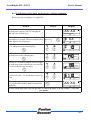
6-c) Verification of the back-up frequency without computer
Realise the test set up figure 3.1 page III-4
Action
Key(s)
#1-Connect the unit on the main power (via the
external power supply), XX.XX is displayed.
(XX.XX is the current time).
#2-Press on the two keys opposite and keep them
depressed for 2 seconds. The menu displayed opposite appears (Set frequency).
Display
XX: XX
Hidden Key
XX
#3-Press on one of the two keys opposite to set
F= 10, and press on the following key:
#4-Select P = 14 cmH2O with the two keys opposite, and press on the following key:
#5-Select P = 8 cmH2O with the two keys opposite, and press on the following key several time
to access to the I/E ratio set menu:
cm H 2 O
cm H2 O
#6-Select I/E ratio = 1:1.0 with the two keys opposite
#7-Press the opposite key as many time as necessary to return into stand by mode (current time
displayed)
XX: XX
Switch on the unit and verify the pressure to run from EPAP to IPAP 10 time +/- one time
per minute.
P/N: M-145MAT00-20 Rev. A - Page Rev.A
III-13
GoodKnight 425 / 425 ST
Service Manual
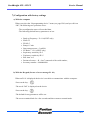
7) Configuration with factory settings
a) With the computer
When you select the “Reprogramming device” menu (see page III-6) and you click on
“OK”, the following two operations occur:
-The reconfiguration erases all recorded data,
-The following default factory parameters are set:
·
·
·
·
·
·
·
·
·
·
·
Back up Frequency: Fr=10 (425ST only)
IPAP=15
EPAP=5
Ramp=15 min
Start ramp pressure = 3cmH2O
I/E Ratio = 1:2.0 (425ST only)
Inspiratory sensitivity SI=5
Expiratory sensitivity SE=5
Rise time: rt=3
Patient reference: = R + last 7 numerals of the serial number,
Inventory number = 0000000000.
b) With the Keypad (In case of error message Er 01)
When an Er 01 is displayed the device is not able to communicate with the computer.
-Press on the key:
-The word “Def” is displayed on the device
-Press on the key:
-The default factory parameters will be set:
-The screen remains blank for a few seconds and then returns to normal mode.
P/N: M-145MAT00-20 Rev. A - Page Rev.A
III-14
GoodKnight 425 / 425 ST
Service Manual
8) Entering the serial number and the hour meter values
1- Follow the same steps as those described on pages III-5 to III-6 (Performance Verification).
2- After entering the password (page III-6), click on the “Serial number and meters”
menu and follow the screen instructions.
CAUTION
The serial number must match the one printed on the base of the device.
The manufacturer is not responsible for any fraudulent use that might result from modification
of the serial number.
9) Service hour meters
The GoodKnight 425/425ST has two additional “tools” to help you in planning the
maintenance of your device.
These two meters can be customized (choice of the name) and can be reset as necessary.
To use it, follow the steps described on pages III-5 and III-6. After entering the password (page III-6), click on the “Serial number and meters” menu and follow the screen
instructions.
P/N: M-145MAT00-20 Rev. A - Page Rev.A
III-15
GoodKnight 425 / 425 ST
Service Manual
10) Setting the clock with the keypad.
Key(s)
Action
#1-The device is in stand-by mode (the clock is
displayed). Press the first key opposite and keep
depressed. Then press the second key opposite
and release the two keys simultaneously.
The display shown opposite appears ( XX:XX is
the clock value to be set). The letter “h” flashes
and the hour value is ready to be adjusted.
#2-Adjust the hours with the two keys opposite
#3-Press the key opposite to adjust the minutes.
The display shown opposite appears. The letters
“min” flash and the minute value is ready to be
adjusted.
#4-Adjust the minutes with the two keys opposite.
#5-Press the key opposite to return to stand-by
mode. (XX:XX is new set time).
and
Display
XX:XX
h
XX:XX
h
XX:XX
min
XX:XX
min
XX: XX
NOTE
The setting of date can be done only with the software Silverlining.
P/N: M-145MAT00-20 Rev. A - Page Rev.A
III-16
GoodKnight 425 / 425 ST
Service Manual
Personal Notes
P/N: M-145MAT00-20 Rev. A - Page Rev.A
III-17
GoodKnight 425 / 425 ST
Service Manual
B. CALIBRATION PROCEDURE
1) Equipment required
*
*
*
*
a calibrated pressure meter
a calibrated leak M-BH210 and a connection tube M-213530-05,
a patient circuit M-261000-27,
a test kit M-212430-02
NOTE
The calibration pressure mode is accessed via the keypad.
The pressure calibration can be also performed by computer using
Silverlining software. Refer to page III-5 and III-6, click on the “Calibration” menu
and follow the instructions.
CAUTION
Measure the pressure during calibration at the end of a 6 ft (1.80 m) patient circuit
sealed with a stopper fitted with a 4 mm diameter leak (figure 3.1 page III-4).
CAUTION
Allow to warm up for 1/2 hour before performing the pressure calibration
P/N: M-145MAT00-20 Rev. A - Page Rev.A
III-18
GoodKnight 425 / 425 ST
Service Manual
2) Pressure sensor calibration
Connect a patient circuit and a pressure meter as shown in figure 3-1 on page III-4
The pressure sensor calibration can be done with a computer and the Technical Menu of the
software Silverlining (procedure described III-7), or with the keypad (procedure described
page III-10).
NOTE
The pressure calibration with the keypad does not allow to verify the pressure higher than
20 cmH2O
The pressure calibration with the keypad does not reboot the unit with the initial settings.
P/N: M-145MAT00-20 Rev. A - Page Rev.A
III-19
GoodKnight 425 / 425 ST
Service Manual
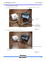
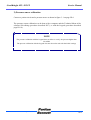
3) Flow sensor calibration
3-a) Set up material
1-Remove the top housing (refer to the disassembly section page III-22),
2-Locate on the MCU board the trimmers TR3 and TR4,
3-Realise the test set up figure 3.1 page III-4
TR4
TR3
4-Connect the unit to the computer,
5-Follow the steps described page III-5 to III-6 and click on “Calibrations/Performances”,
the following menu will appear.
P/N: M-145MAT00-20 Rev. A - Page Rev.A
III-20
GoodKnight 425 / 425 ST
3-b)
Service Manual
Calibration
CAUTION
Allow to warm up for 1/2 hour with a set pressure of 14cmH2O, unit in Cpap
mode, before carrying out the pressure calibration.
1-Replace the test kit with the calibrated output (figure 3.2 page III-4) and block
the output
2-With the mouse, click on the setting cursor of the menu “Flow/Débit” and adjust
the Offset to 0,
3-Store with the button “Storage”,
4-Place TR4 in a medium position,
5-Adjust TR3 for a Value/Valeur reading of 0 l/s +/-0.05 (Value of Flow in the
“Flow/Débit” menu),
6-Leave the calibrated output free and adjust TR4 for a Value/Valeur reading of:
1.2 l/s +/-0.05,
7-Block again the calibrated output and verify that the value reading is:
0 l/s +/-0.05.
If not, repeat the process from the step #5.
Menu "Flow/Débit"
{
Setting Cursor
P/N: M-145MAT00-20 Rev. A - Page Rev.A
III-21
GoodKnight 425 / 425 ST
Service Manual
C. DISASSEMBLY
Material :
A Torx T10 screwdriver,
A grounded wrist strap,
A grounded conductive mat.
WARNING
The GK 425/425ST BiLevel System is electrically powered. To prevent serious
injury or death, follow standard safety procedures. Ensure that power has
been disconnected from the unit before servicing any component.
-Remove the four screws located under the device,
-Remove the top housing,
-Remove the chassis assembly.
CAUTION
After replacing the chassis assembly, enter the serial number and the hour meter value in the device
memory if necessary
P/N: M-145MAT00-20 Rev. A - Page Rev.A
III-22
GoodKnight 425 / 425 ST
Service Manual
Internal Frame assembly
Top
Housing
Bottom
Housing
Inlet baffle
foam
P/N: M-145MAT00-20 Rev. A - Page Rev.A
III-23
GoodKnight 425 / 425 ST
Service Manual
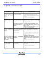
D. TROUBLESHOOTING GUIDE
PROBLEM
PROBABLE CAUSE
SUGGESTIONS
The device does not The ramp is activated.
produce the correct
pressure.
-Check that the ramp indicator is displayed. Press the ramp button to cancel the
function.
-Call your Technical Support
The air output of the The air input filters may be
device is too hot.
dirty.
-Clean or replace the filters accordingly.
Move away any bed linen or clothing from
the GK425/425ST.
The air input is obstructed.
The room temperature is
too high.
-Turn the room thermostat down. Make
sure that the GK425/425ST is not near any
source of heat.
-Remove the tube from under the covers.
-Call your Technical Support
The GK425/GK425ST Check that the external -Check the connection of the external
does not switch on (no power supply module is cor- power supply module to the mains plug.
display).
rectly connected.
No mains supply.
-Use another appliance (e.g.: lamp, radio,
etc) to check that there is an AC current
supply at the plug.
-Call your Technical Support
The device does not Excessive electromagnetic -Keep device away from all sources of diswork correctly and ap- disturbance
turbance, such as mobile phones, halogen
pears to be suffering
lights...
interference
-Call your Technical Support
Er=0XX is displayed The device has detected an
(xx =error code).
operating fault.
-Refer to the “Error Messages” section on
page III-26.
-Call your Technical Support
P/N: M-145MAT00-20 Rev. A - Page Rev.A
III-24
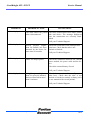
GoodKnight 425 / 425 ST
PROBLEM
In 01 is displayed.
PROBABLE CAUSE
Service Manual
SUGGESTIONS
The mask and/or the patient -Check the connection between mask, patient
tube is disconnected.
tube and device. The message disappears
once the connections are correctly established.
-Call your Technical Support.
In 02 is displayed.
In 03 is displayed.
Excess pressure (higher
than 28 cmH2O) has been
detected by the device for
more than 10 seconds.
-Check the connection of the small pressure
point hose. Check that the tube is not
pinched or blocked.
There is a drop in power.
-Check the connection between the external
power module, the power cable and the device.
-Call your Technical Support
-Check the external battery if used.
In 04 is displayed.
A high frequency (higher
than 30 cycles per minutes)
has been detected for more
than 10 minutes.
-Call your Technical Support
-Check the connection of the small pressure
point hose. Check that the tube is not
pinched or blocked or moistly or dusty (refer
to user manual of the circuit patient).
-Call your Technical Support
P/N: M-145MAT00-20 Rev. A - Page Rev.A
III-25
GoodKnight 425 / 425 ST
Service Manual
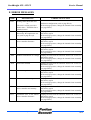
E. ERROR MESSAGES
CODE
DESCRIPTION
CORRECTIVE ACTION
Er01
-Settings data checksum error.
or
-The unit is staying set with a
EPAP value > 20cmH2O after a
technical action.
-Perform reconfiguration (refer to page III-14).
-If the message persists, change the internal frame assembly
(see page III-22).
Er02
A too high temperature has been
detected by the temperature sensor. (refer to page II-4 §5).
-Unplug the unit from all electrical sources for a few seconds and try again.
-If the message persists, change the internal frame assembly
(see page III-22).
Er06
Checksum error in the Master
micro-controller firmware.
-Unplug the unit from all electrical sources for a few seconds and try again.
-If the message persists, change the internal frame assembly
(see page III-22).
Er07
The blower does not work.
-Unplug the unit from all electrical sources for a few seconds and try again.
-If the message persists, change the internal frame assembly
(see page III-22).
Er08
Problem with internal 5V voltage -Unplug the unit from all electrical sources for a few seconds and try again.
-If the message persists, change the internal frame assembly
(see page III-22).
Er10
Power limit reached
-Unplug the unit from all electrical sources for a few seconds and try again.
-If the message persists, change the internal frame assembly
(see page III-22).
Er11
Over consumption
-Unplug the unit from all electrical sources for a few seconds and try again.
-If the message persists, change the internal frame assembly
(see page III-22).
Er15
Error in recorded setting.
Er16
Er 17
-Unplug the unit from all electrical sources for a few seconds and try again.
-If the message persists, change the internal frame assembly
(see page III-22).
Problem with link between master -Unplug the unit from all electrical sources for a few secmicro-controller and memory.
onds and try again.
-If the message persists, change the internal frame assembly
(see page III-22).
Checksum error in the Motor
micro-controller firmware.
P/N: M-145MAT00-20 Rev. A - Page Rev.A
-Unplug the unit from all electrical sources for a few seconds and try again.
-If the message persists, change the internal frame assembly
(see page III-22).
III-26
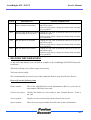
GoodKnight 425 / 425 ST
CODE
¨
Service Manual
DESCRIPTION
ACTION CORRECTIVE
Er18
Problem with link between motor -Unplug the unit from all electrical sources for a few secmicro-controller and memory
onds and try again.
-If the message persists, change the internal frame assembly
(see page III-22).
Er19
Problem with the Bi-Level setting -Unplug the unit from all electrical sources for a few secdata regarding the motor driver.
onds and try again.
-If the message persists, change the internal frame assembly
(see page III-22).
Er40
Bus I2C Motor not available
Er41
Bus I2C Master not available
-Unplug the unit from all electrical sources for a few seconds and try again.
-If the message persists, change the internal frame assembly
(see page III-22).
-Unplug the unit from all electrical sources for a few seconds and try again.
-If the message persists, change the internal frame assembly
(see page III-22).
HISTORY RECORD FORM
At the end of this manual, you will find an example of the GoodKnight 425/425ST History Record Form.
This form will help you in all the stages of servicing.
This form can be copied.
We recommend that you send a copy of the completed forms to your local Factory Service.
How to fill out the following items
Return number
This is the official Return Goods Authorization (RGA) or your own return number if RGA does not exist.
Failure description
Describe the failure in a few words or state “Routine Service” if this is
the case.
Servicing done
Describe in a few words what you have done in the service.
Report number
Enter here your report number if not the same as the return number.
P/N: M-145MAT00-20 Rev. A - Page Rev.A
III-27
GoodKnight 425 / 425 ST
Service Manual
Personal Notes
P/N: M-145MAT00-20 Rev. A - Page Rev.A
III-28
GoodKnight 425 / 425ST
Service Manual
IV - SPARE PARTS
P/N: M-145MAT00-20 Rev. A - Page Rev.A
IV-1
GoodKnight 425 / 425ST
Part #
Service Manual
Description
M-314530-00
Top Housing equipped 425 International
M-314530-01
Top Housing equipped 425ST International
M-314530-02
Top Housing equipped 425 USA
M-314530-03
Top Housing equipped 425ST USA
M-313940-01
Bottom housing 425 / 425ST
M-314560-00
Internal frame assembly 425 (equipped with blower and electronic board
factory set). Inlet baffle foam not included.
M-314560-01
Internal frame assembly 425ST (equipped with blower and electronic
board factory set). Inlet baffle foam not included.
M-413950-01
Inlet baffle foam 425 / 425ST
M-414510-00
External power module 425 / 425ST.
M-660600-04
Power lead Europe.
M-660600-40
Power lead UK
M-660600-39
Power lead USA
M-660600-41
Power lead Australia
M-711902-01
Torx T10 screw for housing.
P/N: M-145MAT00-20 Rev. A - Page Rev.A
IV-2
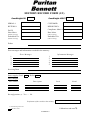
HISTORY RECORD FORM (1/2)
GoodKnight425
GoodKnight 425ST
SERIAL #
CUSTOMER
RETURN #
REPORTING #
DATE
Compliance Meter #
Hour Meter
Hour Meter
(Before servicing)
(After servicing)
Embedded Ver.
Embedded Ver.
(Before servicing)
(After servicing)
Failure
Error messages and information recorded in the memory :
Error Messages
Information Messages
1.
2.
3.
4.
5.
1.
2.
3.
4.
5.
Servicing Done
Power supply: Good
Defect
Parts changed
Part number
Description
Lot #
Serial
Reconfiguration (1): Yes — No
Verification of the serial# in the memory
(1): Surround the good answer
Calibrations and tests Ä
Fill with a value
145FDS002.0
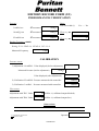
HISTORY RECORD FORM (2/2)
PERFORMANCES VERIFICATION
Pressure
Ramp
Test succeeded (1)
Yes — No
3 cmH2O set
c measured
cmH2O
14 cmH2O set
c measured
cmH2O
Flow (step #1)
l/s
25 cmH2O set
c measured
cmH2O
Flow (step #2)
l/s
Backup Frequency (425ST)
Setting: F=10 IPAP=14 EPAP=8 I/E=1:1.0
Measured Frequency
c/min
CALIBRATION
Pressure sensor
1) Adjustment 14 cmH2O: Value displayed (before adjustment)
Measured Pressure (before adjustment)
cmH2O
Value displayed (after adjustment)
2) Verification 25 cmH2O: Pressure measured with controller:
cmH2O
3) Verification 3 cmH2O: Pressure measured with controller:
cmH2O
Flow sensor
Adjustment with TR3: Value:
l/s (Offset =0, calibrated output blocked)
Adjustment with TR4: Value:
l/s (Offset =0, calibrated output free)
Observations
Operator
(1)= Surround the good answer
Fill with a value
145FDS002.0
GoodKnight 425 / 425ST
P/N: M-145MAT00-20 Rev. A - Page Rev.A
Service Manual
GoodKnight 425 / 425ST
MALLINCKRODT DEVELOPPEMEN FRANCE
Parc d'Activités du Bois St Julien
10 allée Pelletier-Doisy
54601 VILLERS LES NANCY CEDEX
Tél: 33 (0) 3.83.44.85.00
P/N: M-145MAT00-20 Rev. A - Page Rev.A
Service Manual