1
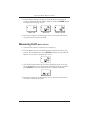
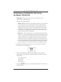
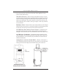
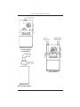
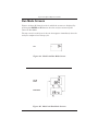
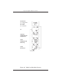
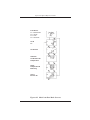
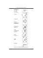
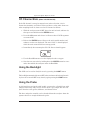
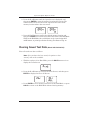
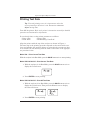
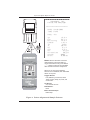
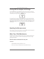
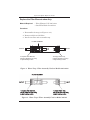
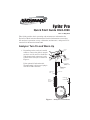
Fyrite Pro
®
Quick Start Guide 0024-9396
Rev. 8 – May 2010
This Guide provides basic operating and maintenance information for
Fyrite Pro Model 100/105/110/120/125. Detailed information concerning
the analyzer’s operation, set up, calibration, maintenance, and parts list is
contained in Instruction 0024-9395.
Analyzer Turn On and Warm Up
1. Depending on the analyzer’s model
number, connect the probe’s samplegas hose and, if used, its draft hose
and thermocouple connector to the
bottom of the analyzer as shown in
Figure 1.
T -S T A C K
T -A IR
+
A C
A D A P T E R
J A C K
If the optional Combustion-Air
Thermocouple is being used, plug it
into the T-AIR connector.
G A S
_
C O M B U S T IO N -A IR
T H E R M O C O U P L E
( O p tio n a l)
D R A F T
D IF F E R E N T IA L
P R E S S U R E H O S E
( O p tio n a l)
S A M P L E G A S
T H E R M O C O U P L E
(T -S T A C K )
S A M P L E -G A S
H O S E
D R A F T H O S E
P R O B E T U B E
P R O B E S T O P
W A T E R
T R A P / F IL T E R
A S S E M B L Y
P R O B E
H A N D L E
Figure 1. Analyzer Connections
Fyrite Pro Quick Reference Guide
2. Turn ON the analyzer by pressing its I/O button and observe that a
series of three Warm-Up Screens are displayed.
The first screen identifies the model number of the analyzer, the
next screen shows the software revision number, while the last
screen counts down the warm-up time from either 10 or 60 seconds.
If an oxygen sensor is installed, its output level is also displayed.
Note: The warm-up time is 10 seconds for analyzers that do
not contain an oxygen sensor, and have their CO channel
set up for manual zero. The warm-up time is 60 seconds for
analyzers that contain an oxygen sensor, and/or have their
CO channel set up for auto zero.
Tip: An O2 error will occur when the oxygen sensor’s output
drops to between 80 and 90. Consider replacing the oxygen
sensor when its output level drops below 100.
3. Wait for the analyzer to count down its warm-up period; after
which, either the CO Screen (Model 100), the CO & Draft Screen
(Model 105), or the Fuel Screen (Model 110/120/125) is displayed.
Model 100
Model 105
Model 110/120/125
Measuring CO (Model 100/105/120/125)
1. Turn ON the analyzer and allow it to warm-up.
Important: If the CO channel is set up for auto zero, then
the analyzer must be turned ON in fresh air; otherwise,
incorrect CO readings will occur. If the CO channel is set
up for manual zero, and if the CO reading is higher than
zero when sampling fresh air, then the CO channel must be
manually zeroed per Section “CO Channel Zero” on Page 13.
2
Instruction 0024-9396
Fyrite Pro Quick Reference Guide
2. For the Model 100/105, the CO or CO & Draft Screen should already be displayed. For the Model 120/125, push the ENTER button
to display the CO & O2 Screen.
Model 100
Model 105
Model 120/125
3. Insert the analyzer’s probe into the area to be tested and observe
the detected CO level on the LCD.
Measuring Draft (Model 105/125)
1. Turn ON the analyzer and allow it to warm-up.
2. For the Model 105, the CO & Draft Screen should already be displayed. For the Model 125, press ENTER and then press the or
button as necessary to display this screen.
3. The draft reading should be zero when sampling room air. If not,
press the button once to display the Draft Zero Screen, and then
press ENTER to zero the draft channel to ambient conditions.
4. Insert the analyzer’s probe into the area to be tested and observe
the draft reading on the LCD.
Instruction 0024-9396
3
Fyrite Pro Quick Reference Guide
Performing a Combustion Test using
the Model 110/120/125
Important: The probe must be at room temperature before
performing the following steps.
1. Perform one of the following:
• Model 110/120 – Before turning ON the analyzer, its probe must
be located in the area containing the burner’s combustion-air
supply. If the burner is using room air, simply place the probe
within the room. In the case of a high-efficiency furnace where
combustion air is drawn in from an outside source, insert the
probe into the combustion-air stream so it can measure its temperature with the burner operating.
• Model 125 – This analyzer has a second thermocouple channel
that can be used to independently monitor the temperature of the
burner’s combustion-air supply. When using this second thermocouple channel, insert the thermocouple into the burner’s combustion-air stream, and position the probe to measure the ambient room temperature. If the second thermocouple channel is not
used, then use the probe’s thermocouple to measure the combustion-air temperature as described above for the Model 110/120.
2. Turn ON the analyzer and allow it to warm-up; after which the
Fuel Screen will be displayed.
3. Use the or button to step through the fuels codes until the
proper fuel is selected. The analyzer defaults to the most recently
selected fuel.
F1 = Natural Gas
F2 = Oil #2
F3 = LPG
F4 = Kerosene
4. Press the ENTER button to select the displayed fuel code and enter
the Run Mode.
4
Instruction 0024-9396
Fyrite Pro Quick Reference Guide
5. Insert the probe into the flue-gas stream of the appliance being
tested as described below:
Forced Air Furnace – When testing atmospheric burner or gravity vented, forced air heating equipment with a clamshell or sectional heat exchanger design, test each of the exhaust ports at the top
of the heat exchanger. The probe should be inserted back into each
of the exhaust ports to obtain a flue gas sample, before any dilution
air is mixed in.
Hot Water Tank – Domestic hot water tanks with the ‘bell’ shaped
draft diverter on top can be accurately tested by inserting the probe
tip directly into the top of the fire tube below the diverter.
80% Efficiency Fan Assist or Power Vented – Combustion testing of fan assist or power vented, furnaces/boilers should be done
through a hole drilled in the vent immediately above the inducer fan.
90% Efficiency Condensing – Condensing furnaces/boilers can be
tested through a hole drilled in the plastic vent pipe (when allowed by
the manufacturer or local authority of jurisdiction) or taken from the
exhaust termination.
Atmospheric or Gravity Vented Boiler – Boilers, which have a
‘bell’ shaped draft diverter directly on top, should be tested directly
below the diverter through a hole drilled in the vent connector.
Atmospheric Burner or
Gravity Vented Forced Air
Instruction 0024-9396
Hot Water Tank
5
Fyrite Pro Quick Reference Guide
80% Eff. Fan Assist
or Power Vented
Furnace/Boiler
90% Eff. Condensing
Furnace/Boiler
Atmospheric or
Gravity Vented Boiler
6
Instruction 0024-9396
Fyrite Pro Quick Reference Guide
6. After turning ON the analyzer and selecting the appropriate fuel,
press the or button to display the Stack Temperature & Efficiency Screen.
7. Position the probe in the flue-gas stream to obtain the hottest
“Stack” reading. Locating the highest stack temperature is very important for accurate efficiency calculations.
8. Burner-service procedures can now begin. Use the and buttons
to scroll through the analyzer’s other display screens (refer to Section Run Mode Screens on Page 8). The analyzer readings will update
continuously showing changes in burner performance.
Note: When a calcuation cannot be made because of improper data (i.e., oxygen level above 17.9%), four dashes
“- - - -” appear in place of the calculated value on both the
screen and printout.
Tip: Pressing the HOLD button will freeze all readings and
stop the pump, allowing the operator to scroll through the
Run Mode Screens and examine the readings at that point in
time. Press ENTER to restart the pump and resume testing.
9. End a test as follows:
WARNING! Burn Hazard. Do not touch the probe after
removing it from the stack. Allow the probe to cool before
handling (about 5 minutes).
a. Remove probe from the flue-gas stream.
b. Allow the pump to run until all combustion gases are flushed
from the analyzer as indicated by the O2 reading returning to
20.9%.
c. Turn OFF the analyzer by pressing the I/O button as described
in Section Turning OFF the Analyzer & CO Purge on Page 18.
Instruction 0024-9396
7
Fyrite Pro Quick Reference Guide
Run Mode Screens
Figures 2A thru 2E show the order in which the screens are displayed by
pressing the ENTER and
buttons after the analyzer warms-up and
enters its Run Mode.
The top screen in each figure is the one that appears immediately after the
analyzer completes its warm-up cycle.
CO
Figure 2A. Model 100 Run Mode Screen
CO &
Draft
Draft Zero
Figure 2B. Model 105 Run Mode Screens
8
Instruction 0024-9396
Fyrite Pro Quick Reference Guide
Fuel Select:
F1 = Natural Gas
F2 = Oil #2
F3 = LPG
F4 = Kerosene
O2
Ambient /
Combustion Air
Temperature
Stack
Temperature &
Efficiency
CO2 &
Excess Air
Figure 2C. Model 110 Run Mode Screens
Instruction 0024-9396
9
Fyrite Pro Quick Reference Guide
Fuel Select:
F1 = Natural Gas
F2 = Oil #2
F3 = LPG
F4 = Kerosene
CO &
O2
CO Air Free
Ambient /
Combustion Air
Temperature
Stack
Temperature &
Efficiency
CO2 &
Excess Air
Figure 2D. Model 120 Run Mode Screens
10
Instruction 0024-9396
Fyrite Pro Quick Reference Guide
Fuel Select:
F1 = Natural Gas
F2 = Oil #2
F3 = LPG
F4 = Kerosene
CO & O2
CO Air Free
Ambient /
Combustion Air
Temperature
Temperature
Differential
Stack
Temperature &
Efficiency
CO2 &
Excess Air
CO &
Draft
Draft Zero
Figure 2E. Model 125 Run Mode Screens
Instruction 0024-9396
11
Fyrite Pro Quick Reference Guide
Operating Tips
• When an analyzer is brought in from a cold vehicle, let it warm up
slowly to minimize condensation. Temperatures below freezing will not
damage the analyzer; however, bringing a cold analyzer into a warm,
humid environment may cause condensate to form inside the case.
• If the CO channel (Model 100/105/120/125) is set up for Auto Zero (refer
to Section 3.5.3 in Instruction 0024-9395), ensure that the analyzer is
sampling fresh air when turned ON. Pulling a flue-gas sample through
the analyzer during its warm-up period will not damage the analyzer, but
it will result in incorrect CO readings. Also note that a CO sensor error
will occur if the detected CO level is above 50 ppm during warm-up.
• For analyzers that are used to measure flue-gas, note that flue-gas
condensate is acidic and very corrosive. It is important not to allow
the analyzer’s internal components to become soaked in condensate for
long periods of time.
• Before each use, inspect the filter element of the water-trap / filter assembly. Replace the filter if it looks dirty (refer to Section Water Trap /
Filter Maintenance on Page 18).
• When sampling flue-gas, keep the analyzer above the water-trap, and
keep the trap in a vertical position. This will maximize the effectiveness of the trap and keep liquid condensate from being drawn directly
into the analyzer.
• When liquid condensate is seen inside the water trap, empty the trap
before it becomes full (refer to Section Water Trap / Filter Maintenance
on Page 18).
• It is recommended that the analyzer be purged after taking a flue-gas
measurement before turning it OFF. Once the probe is removed from
the stack, disconnect the hose assembly from the bottom of the analyzer and let the pump run for 10 minutes or so to completely remove any
remaining flue gases and dry any condensate from inside the sensor
chamber.
• When storing the analyzer, it’s a good idea to empty the water trap and
leave it open to further dry it out.
• Calibrate the analyzer about every 6 months to ensure its accuracy.
12
Instruction 0024-9396
Fyrite Pro Quick Reference Guide
CO Channel Zero (Model 100/105/120/125)
If the CO channel is set up for manual zero (refer to Section 3.5.3 in
Instruction 24-9395), and if the CO Screen shows a value other than zero
when sampling fresh air, then zero the CO channel as follows:
1. With the analyzer turned OFF, place the unit in fresh, ambient air;
then press and hold down the ENTER button.
2. Press the I/O button and release it. Observe that all LCD segments
are turned ON.
3. Release the ENTER button. Observe the unit’s model number and
software version are displayed. The word “CAL” is then displayed
while the unit counts down its warm-up period.
4. Immediately after warmup the CO CAL Screen should appear.
5. Use the
and
buttons to set the displayed value to 0 ppm.
6. Save the new zero value by holding down the ENTER button for 2 seconds; after which, the analyzer enters its Run Mode.
Using the Backlight
The LCD can be read in dimly-lit areas by pressing the LIGHT button.
The backlight automatically turns OFF after 10 minutes of keyboard inactivity, but can be turned OFF at any time by again pressing the LIGHT button.
Using the Probe
A rigid stainless steel probe with handle, connected to a flexible hose with
integral water-trap / filter can be used to draw a gas sample into the analyzer from the room, grilles, diffusers, and furnace flues.
The hose and probe assembly can be detached from the analyzer when the
operator desires to sample without the probe.
Instruction 0024-9396
13
Fyrite Pro Quick Reference Guide
Saving Test Data in Memory (Model 105/110/120/125)
Up to 10 individual sets of test data can be saved in memory as follows:
Note: When memory is full, the next reading saved will overwrite the oldest reading.
Note: The analyzer’s setup information is stored along with
the test data. For example, temperatures stored in °C are
recalled and printed in °C even if the analyzer is currently set
up for °F.
1. With the analyzer is in its Run Mode, press the HOLD button twice
to display the Print Screen.
2. Press the button once to display the Save Screen. The number
shown in this screen represents the memory location (1 thru 10) to
which the current test data will be saved.
3. Press ENTER to save the test data and return to the Hold Mode, or
press HOLD to return to the Hold Mode without saving.
Opening and Viewing Saved Test Data
(Model 105/110/120/125)
Perform the following to open and view saved test data:
Note: If no test data has been saved, the option to open the
memory for viewing will not be available.
1. With the analyzer is in its Run Mode, press the HOLD button twice
to display the Print Screen.
14
Instruction 0024-9396
Fyrite Pro Quick Reference Guide
2. Press the or button until the Open Screen is displayed, and
then press ENTER to open the memory locations for viewing. The
number shown in the second screen represents the most recent
memory location where data was stored.
3. Press the or button to scroll to the desired memory location, and
then press ENTER to recall the stored data and return to the Hold Mode.
While in the Hold Mode, the recalled data can be viewed using the
and buttons, or printed per Section Printing Test Data on Page 16.
Clearing Saved Test Data (Model 105/110/120/125)
Clear all saved test data as follows:
Note: If no test data has been saved, the option to clear
memory will not be available.
1. With the analzyer in its Run Mode, press the HOLD button twice to
display the Print Screen.
2. Press the or button to scroll to the Clear Screen, and then press
ENTER to display the Clear All Screen.
3. Press ENTER to clear memory and return to the Hold Mode, or press
HOLD to return to the Hold Mode without clearing memory.
Instruction 0024-9396
15
Fyrite Pro Quick Reference Guide
Printing Test Data
Tip: To avoid printing errors, it is important to select the
correct protocol per Section 3.5.8 in Instruction 0024-9395
before saving data.
Turn ON the printer. Refer to the printer’s instruction manual for detailed
operation and maintenance information.
If not already done, set the printer parameters as follows:
• Data: 8 bits
• Parity: None
• Baud: 9600
• Handshaking: X-on/X-off
Align the printer with the top of the analyzer as shown in Figure 3.
The next step in the printing procedure depends on the model of the analyzer, and whether the operator desires to print only the current test data,
or all stored test data starting with the most recent. Refer to the appropriate procedure below:
Model 100 – Print Current Test Data
With the analyzer in its Run Mode, press the HOLD button twice to start printing.
Model 105/110/120/125 – Print Current Test Data
1. With the analzyer in its Run Mode, press the HOLD button twice to
display the Print Screen.
2. Press ENTER to start printing.
Model 105/110/120/125 – Print All Test Data
1. With the analyzer in its Run Mode, press the HOLD button twice to
display the Print Screen. Then press the button once to display
the Print All Screen.
2. Press ENTER to start printing.
16
Instruction 0024-9396
Fyrite Pro Quick Reference Guide
B A C H A R A C H , I N C .
F Y R I T E P R O A N A L Y Z E R
= = = = = = = = = = = = = = = = = = = = = = =
D A T E :
T I M E :
2 9 / 1 0 / 2 0 0 3
1 4 : 4 5
F U E L :
( F 1 )
q A
E T
E f
L a
T A
T L
O 2
C O
C O
C O
C O
D r
f i c i e n c y
m b d a
1 5
8 4
7 4
1 .
2
3 0
6
9
a
U n d i l u t e
/ C O 2
a f t
3
. 0 0
0 .
. 9 %
. 1 %
. 5 %
4 1 %
2 9 ° C
. 7 ° C
. 1 %
. 3 %
5 7 p p m
8 0 p p m
0 6
0 0 m B
Notes: When a calcuation cannot be
made because of improper data (i.e.,
oxygen level above 17.9%), four dashes
“- - - -” appear in place of the calculated
value on both the screen and printout.
When one or more of the following
sensors are not installed, their associated
values do not print:
Oxygen Sensor:
Fuel, Efficiency, Excess Air, Stack
Temp, Primary Temp, O2, CO2, and
CO Air Free
CO Sensor:
CO, and CO Air Free
Draft Sensor:
Draft
Either Thermocouple:
Delta Temp
Figure 3. Printer Alignment & Sample Printout
Instruction 0024-9396
17
Fyrite Pro Quick Reference Guide
Turning OFF the Analyzer & CO Purge
Press the I/O button to turn OFF the analyzer. The unit will count down
from 5 before turning OFF, thus allowing time for the operator to abort the
turn OFF process by pressing the ENTER button.
If a high CO level is detected at turn OFF, the unit will remain ON with
its pump running and display “PUrG CO”. The countdown from 5 will not
begin until the detected CO level drops below 50 ppm. Although not recommended, the purging process can be bypassed by pressing the I/O button a
second time.
Resetting the Microprocessor
If the analyzer ‘locks up’ and cannot be turned OFF, reset the microprocessor by removing one of the batteries for 5 seconds.
Water Trap / Filter Maintenance
The Water Trap / Filter Assembly removes water condensate from the gas
sample, and also prevents soot from contaminating the internal components of the analyzer.
Drain the water condensate after every test.
Procedure:
1. Disassemble the trap (see Figure 4 or 5).
2. Pour out all water condensate; then reassemble the trap.
18
Instruction 0024-9396
Fyrite Pro Quick Reference Guide
Replace the Filter Element when dirty.
Material Required:
• Filter Element, P/N 0007-1644
• Small Flat Blade Screwdriver
Procedure:
1. Disassemble the trap (see Figure 4 or 5).
2. Remove and discard old filter.
3. Install new filter and reassemble trap.
F IL T E R E L E M E N T
O U T L E T
T o r e p la c e F ilte r E le m e n t,
p u ll o ff O u tle t E n d C a p u s in g
a s lig h t tw is tin g m o tio n .
IN L E T
T o e m p ty W a te r T ra p ,
p u ll o ff In le t E n d C a p u s in g
a s lig h t tw is tin g m o tio n .
Figure 4. Water Trap / Filter Assembly Used on Model 100/110/120
Figure 5. Water Trap / Filter Assembly Used on Model 105/125
Instruction 0024-9396
19
World Headquarters
621 Hunt Valley Circle, New Kensington, PA 15068
Ph: 724-334-5000 • Fax: 724-334-5001 • Toll Free: 800-736-4666
Web site: www.mybacharach.com • E-mail: [email protected]
Printed in U.S.A.