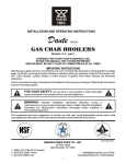
1
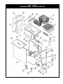
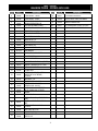
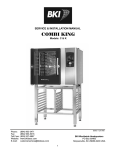
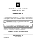
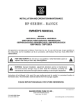
INSTALLATION AND OPERATION MAINTENANCE
FRYERS OWNER’S MANUAL
Models: BPF-3540, BPF-4050, BP-6575
FOR YOUR SAFETY: Do not store or use gasoline or other flammable vapors or
liquids in the vicinity of this or any other appliance.
WARNING: Improper installation, adjustment, alteration, service or maintenance
can cause property damage, injury or death. Read the installation, operating and
maintenance instructions thoroughly before installing or servicing this equipment.
Instruction to be followed in the event the user smells gas shall be posted in a prominent location.
This information shall be obtained by consulting the local gas supplier.
PLEASE RETAIN THIS MANUAL FOR FUTURE REFERENCES.
This equipment is design engineered for commercial use only.
P/N 300291 05/11
BAKERS PRIDE OVEN CO. INC.,
2205 South Standard Avenue
Santa Ana, CA 92707
(714) 424-9380 Phone
(714) 424-9385 Fax
www.bakerspride.com Web address
1
TABLE OF CONTENTS
Installation Instructions ...........................................................................................................................2
Operating Instructions.............................................................................................................................3
Maintenance Instructions ........................................................................................................................5
Exploded View ........................................................................................................................................6
Parts List .................................................................................................................................................7
Warranty ................................................................................................................................................8
IMPORTANT
Installing, Operating and Service Personnel:
•
Installation of the equipment should be performed by qualified, certified, licensed and/or authorized
personnel who are familiar with and experienced in state/local installation codes.
•
Operation of the equipment should be performed by qualified or authorized personnel who have
read this manual and are familiar with the functions of the equipment.
•
Service of the equipment should be performed by qualified personnel who are knowledgeable with
Bakers Pride equipment.
SHIPPING DAMAGE CLAIM PROCEDURE
The equipment is inspected & crated carefully by skilled personnel before leaving factory. The
transportation company assumes full responsibility for safe delivery upon acceptance of this
equipment. If shipment arrives damaged:
1. Visible loss or damage: Note on freight bill or express delivery and have signed by the person
making delivery.
2. File claim for damages immediately: Regardless of the extent of damages.
3. Concealed loss or damage: If damage is noticed after unpacking, notify the transportation
company immediately and file 'Concealed Damage' claim with the transportation carrier. This
should be done within fifteen (15) days from the date delivery and receipt of goods. Retain
container for inspection.
INSTALLATION INSTRUCTIONS
The area around the appliance must be kept free and clear of combustibles such as solvents, cleaning
liquid, broom, rags, etc.
Proper clearances must be provided at the front of the appliance for servicing and proper operation.
Provisions shall be incorporated in the design of the kitchen, to ensure adequate supply of fresh air and
adequate clearance for air openings into the combustion chamber, for proper combustion, and
ventilation.
For proper operation of the appliance, do not obstruct the flow of combustion and ventilation air.
2
The installation must conform with local codes, or in the absence of local codes, with the national fuel
gas code, ANSI Z223.1 - 1988 (or latest addenda), National gas installation code, CAN/CGA - B 149.1,
or the propane installation code, CAN/CGA - B 149.2 as applicable.
The appliance and its individual shut off valve must be disconnected from the gas supply piping system
during any pressure testing of that system in excess of ½ PSI.
The appliance must be isolated from the gas supply piping system by closing its individual manual shut
off valve during any pressure testing of the gas supply piping system at test pressures equal to or less
than ½ PSI.
The gas supply line must be at least the same size as the gas inlet of the appliance.
CLEARANCES
Sides
Rear
Floor
Non-combustible
6"
6"
6"
Combustible
0"
0"
0"
Installation on non-combustible floor shall be with factory supplied legs or casters.
OPERATING INSTRUCTIONS
WARNING
Hot oil and hot surfaces can cause severe burns. Use caution when operating
the fryer.
Do not attempt to move the fryer filled with hot oil or shortening.
Do not go near the area directly above the flue when fryer is in operation.
Severe burns may be caused.
Drain hot oil in metal containers, do not use plastic buckets or glass containers.
LIGHTING INSTRUCTIONS
1. Set the thermostat and the gas cock dial on the combination gas valve to the "OFF" position.
2. Wait for five minutes.
3. Turn gas cock dial on the combination gas valve to "Pilot" position.
4. Depress the gas cock dial and apply a lighted match or taper to the pilot.
5. Hold the gas cock dial depressed for about 30 seconds or until pilot stays lit before releasing.
6. If the pilot does not stay lit, repeat step 4 and 5.
BURNERS / THERMOSTAT OPERATION
1. After the pilot is lit, turn the gas cock dial to "ON" position.
2. Turn the thermostat dial to any temperature setting and observe the burners ignition. It should ignite
within four seconds.
3
CAUTION: Main burners shall not be "ON" when the vessel is empty. During
testing, fill the vessel with liquid (oil or water) till above the heat transfer tubes.
FLEXIBLE COUPLINGS, CONNECTORS AND CASTERS
If the unit is to be installed with casters, the installation shall be made with a connector that complies
with the Standard for Connectors for Movable Gas Appliances, ANSI Z21.69 or Connectors for
Moveable Gas Appliances, CAN/CGA-6.16, and a quick-disconnect device that complies with the
Standard for Quick-Disconnect Devices for Use With Gas Fuel, ANSI Z21.41, or Quick Disconnect
Devices for Use with Gas Fuel CAN1-6.9. Locking front casters are provided to limit the movement of
the appliance without depending on the connector or associated piping. A suitable strain relief must be
installed with the flexible connector.
Restraining device may be attached to the back frame/panel of the unit.
All connections must be sealed with a joint compound suitable for LP gas and all connections must be
tested with a soapy water solution before lighting pilots.
PREPARATION FOR USE
New units have a coating of oil on the interior of the vessel. Remove this coating with hot soapy water,
washing soda, or any other grease dissolving liquid. Rinse thoroughly and drain until all residues are
removed. Wipe dry.
Clean the baskets, crumb screen.
PILOT OPERATION
Check and make sure the pilot is lit. If not, refer to previous section for lighting the pilot.
BEFORE TURNING THE BURNERS ON
1. Fill the vessel with liquid shortening or oil up to the "oil level" marking.
2. Block of solid shortening should not be melted by setting it on top of tubes. This will damage the
vessel and scorch fat. Either melt it first on another appliance or cut into small pieces and pack
tightly below, between and above the burner tubes, without leaving any air spaces around the
tubes. Turn the burners "ON" for about 10 seconds and turn "OFF" for about a minute. Repeat this
"ON-OFF" cycle until all the shortening is melted. If scorching occurs, lower the "ON" time.
3. Do not overfill the vessel.
MAIN BURNER OPERATION
After the vessel is filled with liquid shortening or oil, set the gas cock dial on the combination gas valve
to the "ON" position.
Turn the thermostat to desired temperature setting.
DAILY SHUT-DOWN
At the end of the day, turn the gas cock dial on the combination gas valve and the thermostat to OFF
position. Where applicable turn the power switch to OFF position. Filter the oil in all fryers.
4
MAINTENANCE INSTRUCTIONS
CLEANING
For continued performance efficiency and longevity of your Fryer it is essential to carry out a good
maintenance program.
DAILY
1. Remove and wash thoroughly all "loose" parts (basket hanger, baskets, crumb screen, etc.).
2. Wipe clean all exterior and interior accessible surfaces and parts.
3. Filter the liquid oil/shortening at the end of the day, replace if necessary. If fryer is under heavy use,
filter more often during the day.
WEEKLY
1. Shut down the fryer by turning off the gas cock dial and power supply, where applicable.
2. Drain the fryer in a filter pan or steel container. Flush out sediments at the bottom of the vessel with
liquid oil.
3. Close the drain valve and fill the vessel with a mixture of boil-out solution and water.
4. Relight the pilot and turn on the burners.
5. When the solution starts to boil, turn off the thermostat and let the vessel soak to soften the deposit
and/or carbon spots. (Approximately 1 hour).
6. Drain off solution, scrub the insides with brush and rinse thoroughly.
7. Repeat the cleaning procedure, if necessary.
8. Wipe dry with soft towels and refill with clean oil/shortening.
WARNING: All water must be removed before adding oil or shortening. Not doing
so can result in splattering of hot oil.
STAINLESS STEEL PARTS
Do not use steel wool, abrasive cloths, cleansers or powders to clean stainless steel surfaces. All
stainless steel parts should be wiped regularly with hot soapy water during the day and a stainless steel
liquid cleaner at the end of the day. To remove encrusted materials, soak in hot water to loosen the
material, and then use a wood or nylon scraper.
Contact the factory, factory representative or a local service company to perform maintenance and
repairs.
5
BPF - 40/50
BAKERS PRIDE - FRYER 40/50 LBS
6
BPF - 40/50
BAKERS PRIDE - FRYER 40/50 LBS
Item
Part #
2
300359
FRYER BASKET - LARGE
35
3
5
300189
300922
300923
300436
FRYER BASKET - SMALL
CRUMB SCREEN FINE MESH
CRUMB SCREEN REGULAR
DIFFUSER WELDMENT PANEL
6
300231
PILOT BURNER - NATURAL (FRYER)
7
300359
ORIFICE BELL #16 (LP)
8
300157
THERMOPILE 32" FRYER
9
300260
DRAIN EXTENSION PIPE
10
300239
DRAIN VALVE 1 1/4
11
300921
LANDING LEDGE
12
300443
DOOR HINGE TOP
13
300446
DOOR ASSY FRYER 40/50
14
8717700
DOOR MAGNET
15
U1066A
NAMEPLATE BAKERS PRIDE
16
300228
HI - LIMIT SWITCH
17
300150
DOOR HINGE BOTTOM
18
300229
KNOB THERMOST WITH DIAL (FRYER)
19
300113
BRACKET THERMOSTAT/ HI - LIMIT
20
300232
THERMOSTAT - FRYER
21
22
311039
340264
340265
23
300155
6" CONE LEGS
CASTER (WITH BRAKE) - OPTIONAL
CASTER (WITH OUT BRAKE) OPTIONAL
SIDE PANEL - L/H
24
27
300259
300532
300552
300188
300225
300191
MANIFOLD TSF 40/50 ASSY
ORIFICE HOOD - # 32 (NAT)
ORIFICE HOOD - # 52 (LP)
VALVE, COMBO GAS NAT FRYER
VALVE, COMBO GAS LP FRYER
BURNER
28
300156
29
300120
30
300114
31
300440
32
300456
SIDE PANEL - R/H
VESSEL WELD ASSY (3 TUBE FRYER
TANK)
PROBE HOLDER THERMOSTAT/ HILIMIT
VESSEL COVER W/ HANDLE OPTIONAL
BACK PANEL BOTTOM
33
300138
300445
300444
BACK PANEL TOP
UPPER FLUE PLATE
UPPER FLUE
4
25
26
34
Description
Item
7
36
Part #
300357
300111
300439
Description
FLUE FRONT FRYER 40/50
FLUE REAR FRYER 40/50
UPPER FRONT PANEL, WELDMENT
37
300152
BASKET HANGER 40/50
N/S
300271
KIT, CONVERSION TO NAT TSF- 4050
N/S
300223
KIT, CONVERSION TO LP TSF-4050
BAKERS PRIDE LIMITED WARRANTY
2205 S. Standard Avenue, Santa Ana, CA 92707
Phone: (714) 424-9380 w Fax:(714) 424-9385
WHAT IS COVERED
This warranty covers defects in material and workmanship under normal use, and applies only to the original purchaser
providing that:
•
•
•
The equipment has not been accidentally or intentionally damaged, altered or misused;
The equipment is properly installed, adjusted, operated and maintained in accordance with National and local codes
and in accordance with the installation instruction provided with the product;
The serial number rating plate affixed to the equipment has not been defaced or removed.
WHO IS COVERED
This warranty is extended to the original purchaser and applies only to equipment purchased for use in the U.S.A.
COVERAGE PERIOD
Cyclone Convection Ovens: BCO Models: One (1) Year limited parts and labor; (1) Year limited door warranty.
GDCO Models: Two (2) Year limited parts and labor; (2) Year limited door warranty.
CO11 Models: Two (2) Year limited parts and labor; (5) Year limited door warranty.
All Other Products: One (1) Year limited parts and labor. Warranty period begins the date of dealer invoice to customer or
ninety (90) days after shipment date from BAKERS PRIDE - whichever comes first.
WARRANTY
COVERAGE
This warranty covers on-site labor, parts and reasonable travel time and travel expenses of the authorized service
representative up to (100) miles, round trip, and (2) hours travel time. The purchaser, however, shall be responsible for all
expenses related to travel, including time, mileage and shipping expenses on smaller counter models that may be carried
into a Factory Authorized Service Center, including the following models: PX-14, PX-16, P18, P22S, P24S, PD-4, PDC,
WS Series and BK-18.
EXCEPTIONS
All removable parts in BAKERS PRIDE Char-broilers, including but not limited to: Burners, Grates, Radiants, Stones and
Valves, are covered for a period of SIX MONTHS. All Ceramic Baking Decks are covered for a period of THREE
MONTHS. The installation of these replacement decks is the responsibility of the purchaser. The extended Cyclone door
warranty years 3 through 5 is a parts only warranty and does not include labor, travel, milage or any other charges.
EXCLUSIONS
• Negligence or acts of God,
• Thermostat calibrations after (30) days from equipment
installation date,
• Air and Gas adjustments,
• Light bulbs,
• Glass doors and door adjustments,
• Fuses,
• Char-broiler work decks and cutting boards,
• Tightening of conveyor chains,
• Adjustments to burner flames and cleaning of pilot burners,
• Tightening of screws or fasteners.
INSTALLATION
•
•
•
•
•
•
•
•
Failures caused by erratic voltages or gas supplies,
Unauthorized repair by anyone other than a BAKERS PRIDE
Factory Authorized Service Center,
Damage in shipment,
Alteration, misuse or improper installation,
Thermostats and safety valves with broken capillary tubes,
Accessories — spatulas, forks, steak turners, grate lifters, oven
brushes, scrapers, peels. etc.,
Freight — other than normal UPS charges,
Ordinary wear and tear.
Leveling and installation of decks as well as proper installation and check out of all new equipment —per
appropriate installation and use materials — is the responsibility of the dealer or installer, not the manufacturer.
REPLACEMENT PARTS
BAKERS PRIDE genuine Factory OEM parts receive a (90) day materials warranty effective from the date of
installation by a BAKERS PRIDE Factory Authorized Service Center.
This Warranty is in lieu of all other warranties, expressed or implied, and all other obligations or liabilities on the manufacturer’s part. BAKERS PRIDE
shall in no event be liable for any special, indirect or consequential damages, or in any event for damages in excess of the purchase price of the unit. The
repair or replacement of proven defective parts shall constitute a fulfillment of all obligations under the terms of this warranty.
Form #U4177A 1/07
8
BAKERS PRIDE OVEN CO. INC
2205 S. Standard Avenue
Santa Ana, CA 92707
(714) 424-9380 Phone
(714) 424-9385 Fax
www.bakerspride.com Web Address
9