1
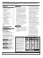
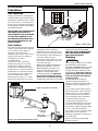
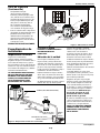
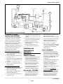
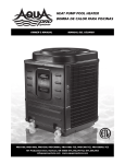
HEAT PUMP POOL HEATER
BOMBA DE CALOR
PARA PISCINAS
OWNER'S MANUAL
MANUAL DEL USUARIO
PRO400, PRO600, and PRO1000
101 Production Drive, Harrison, OH 45030 877.278.2797 fax 877.289.2963
[email protected] www.aquaprosystems.com
© 2006 AquaPro Systems
322802-013 2/07
Operating Instructions
Please read and save these instructions. Read carefully before attempting to assemble, install, operate or maintain the product described.
Protect yourself and others by observing all safety information. Failure to comply with instructions could result in personal injury and/or
property damage! Retain instructions for future reference.
Contents
Important Safety Instructions . . . . . . .2
•
The water in a pool or spa should
never exceed 104ºF (40ºC). A water
temperature in excess of 104ºF is
considered unsafe for all persons.
Lower water temperatures are
recommended for extended use
(exceeding 10-15 minutes) and
young children.
Excessive water temperatures have
a high potential for causing fetal
damage during the early months of
pregnancy. Pregnant or possibly
pregnant women should limit pool
or spa water temperatures to 100ºF
(38ºC).
Alcohol, drugs, or medication
should not be used before or during
pool or spa use since their use may
lead to unconsciousness with the
possibility of drowning.
Pool Chemistry and Warranty . . . . . . .2
Installation Procedures . . . . . . . . . . . .3
Unit Inspection . . . . . . . . . . . . . . . .3
Unit Location . . . . . . . . . . . . . . . . . .3
Plumbing . . . . . . . . . . . . . . . . . . . . .3
Basic Heat Pump Operation . . . . . . . .4
Electrical Connections . . . . . . . . . . .4
Manual Temperature Controls . . . . . .5
Description . . . . . . . . . . . . . . . . . . . .5
Indicator Lights . . . . . . . . . . . . . . . .5
Water Temperature Set Point . . . .5
Application Guidelines . . . . . . . . . . . .5
Maintenance . . . . . . . . . . . . . . . . . .5
Condensation . . . . . . . . . . . . . . . . .6
Pool Blankets . . . . . . . . . . . . . . . . . .6
Seasonal Shutdowns . . . . . . . . . . . .6
Pool Openings . . . . . . . . . . . . . . . . .6
Weather Conditions . . . . . . . . . . . .6
•
•
Troubleshooting Guide . . . . . . . . . . . .6
Warranty . . . . . . . . . . . . . . . . . . . . . . . .7
Important Safety
Instructions
READ AND FOLLOW ALL
INSTRUCTIONS.
Safety Guidelines
This manual contains information that
is very important to know and
understand. This information is
provided for SAFETY and to PREVENT
EQUIPMENT PROBLEMS. To help
recognize this information, observe the
following symbols.
Warning indicates
!
a potentially
hazardous situation which, if not
avoided, could result in death or
serious injury.
WARNING
Caution indicates
a potentially
hazardous situation which, if not
avoided, may result in minor or
moderate injury.
!
CAUTION
Notice indicates
important
information, that if not followed, may
cause damage to equipment.
NOTICE
•
! WARNING
!
•
•
CAUTION
Obese persons and persons with a
medical history of heart disease, low
or high blood pressure, circulatory
system problems, or diabetes should
consult a physician before using a
pool or spa.
•
Persons using medication should
consult a physician before using a
pool or spa since some medication
may induce drowsiness while other
medication may affect heart rate,
blood pressure, and circulation.
Prolonged immersion in hot water
may induce hyperthermia.
Hyperthermia occurs when the
internal temperature of the body
reaches a level several degrees
above the normal body
temperature of 98.6ºF. The
symptoms of hyperthermia include
dizziness, fainting, drowsiness,
lethargy, and an increase in the
internal temperature of the body.
The effects of hyperthermia
include: unawareness of impending
hazard; failure to perceive heat;
failure to recognize the need to exit
pool or spa; physical inability to exit
pool or spa; fetal damage in
pregnant women; and
unconsciousness resulting in a
danger of drowning.
Because the tolerance of water
temperature-regulating devices
may vary as much as ±5ºF (±3ºC),
you should measure the water
temperature at several locations
using an accurate thermometer
before entering a pool or spa.
SAVE THESE INSTRUCTIONS.
Pool Chemistry and Warranty (PRO400 & PRO600)
Maintaining pool chemistry at
the correct levels is critical for
health and pool/spa equipment
reasons. Failure to maintain
industry recognized standards
for proper pool chemistry will
void your warranty on the
PRO400 & PRO600. This chart
contains the recommended
levels for a typical pool. If you
have questions about
maintaining your pool and its
chemistry, consult your local
APSP/NSPI pool professional or
call 877-278-2797 to talk to an
AquaPro representative.
REMINDER: Keep your dated proof of purchase for warranty purposes! Attach it to this manual or file it for safekeeping.
www.aquaprosystems.com
1-877-AQUASYS
2
PRO400, PRO600, PRO1000
Installation
Procedures
Unit Inspection
Inspect your unit very carefully before
installing. Make sure there has been no
damage to the evaporator fins or there
are no punctures or oil-soaked areas on
the box. This would indicate damage to
the refrigeration system and should be
rejected immediately.
5’ Minimum
18”
Min.
THE UNIT MUST BE TRANSPORTED IN
THE UPRIGHT POSITION AT ALL
TIMES AND MUST NOT BE DROPPED
OR TAILGATED. DAMAGE TO THE
UNIT DURING TRANSPORTATION IS
NOT THE RESPONSIBILITY OF THE
MANUFACTURER.
in.
M
”
18
18”
Min.
in.
M
”
36
Figure 1 - Unit Location
Unit Location
Once the unit has been inspected and
cleared of any transportation damage,
it is now time to locate the pool
heater. It is very important to
understand the location of the unit for
the best performance of operation.
See Figure 1 for location
recommendations.
A minimum of 18” of clearance
between the evaporator coils and
shrubs, fences, walls, etc. must be
maintained for adequate air intake.
A minimum of 5’ of vertical clearance
between the top of the unit and any
roof overhang or other obstructions
must be maintained in order to
prevent the re-circulation of cold air
back into the evaporator coils. This is
to maintain the efficiency of the unit.
A minimum of 36” of clearance
between the front of the unit (access
panel area) and any obstruction must
be maintained to allow maintenance
on the unit when necessary.
The unit should be located on a solid
level surface, a minimum of 36”x 36”
for proper drainage.
Make sure any sprinkler heads are not
directly spraying water on the unit.
While heat pumps are made for an
outdoor environment, they are not
designed to have sprinkler water
constantly spraying them. NOTE: This
type of constant watering directly
on the unit can void your warranty.
Condensation drain holes are provided
UNIONS (INCLUDED WITH PRO1000)
IN
FILTER
OUT
CHECK
VALVE
in all units for adequate removal of
condensation and rainwater. ALL
UNITS WILL HAVE CONDENSATION.
THIS SHOULD NOT BE MISTAKEN
FOR A LEAK IN THE UNIT.
Plumbing
NOTICE
Where freezing weather is encountered,
the detachable connection/union
(provided on PRO1000) must be installed
immediately adjacent to the heater to
facilitate servicing and draining of the
heat exchanger. Draining is necessary
to prevent damage to the condenser
shell and coil due to the expansion
of freezing water.
The minimum water circulation
capacity flowing through the pool
heater is 25 gallons per minute and the
maximum capacity is 80 gallons per
minute.
Do not install a water shutoff valve in
the piping from the outlet of the pool
heater to the pool or spa. However, a
check valve that does not include a
shut-off feature may be installed for
convenience during servicing.
A check valve or Hartford Loop is
recommended between the unit and a
chlorinator. The chlorinator must be
downstream of the heat pump. Failure
to do so may void the warranty.
CHLORONATOR
WARM
WATER OUT
TO POOL
POOL
PUMP
COLD WATER
IN FROM POOL
If you have an in-floor cleaning system,
please take note of any special
plumbing requirements to operate all
units effectively.
Figure 2 shows the recommended
installation layout.
Figure 2 - Recommended installation layout
1-877-AQUASYS
www.aquaprosystems.com
3
Operating Instructions
Figure 3 - PRO400 & PRO600 Wiring Diagram
Basic Heat Pump
Operation
See Figure 3 for wiring schematic of
PRO400 & PRO600. See Figure 6 for
wiring schematic of PRO1000.
Electrical Connections
Connecting to Remote
System (PRO1000 only)
All wiring and
! WARNING electrical
connections must be performed by a
qualified electrician. Installations must
be in accordance with local and
national codes.
Overheating, shortcircuiting and fire
damage will result from inadequate
wiring.
!
CAUTION
All units are equipped with an electrical
wiring schematic inside the electrical
panel. If this is missing, please contact
the factory at 1-877-278-2797 to obtain
one.
All units are to be wired for 230 VAC,
1 phase. Please see following chart for
correct amperage:
HEAT
PUMP
BREAKER
OR FUSE
PRO400
20-amp
PRO600
30-amp
PRO1000
50-amp
Pool Heater is to be installed in
accordance with Article 680 of the
National Electrical Code (NEC), NFPA
70, and within the requirements of all
local codes having jurisdiction.
The PRO1000 Pool Heater is compatible
with all known remote systems in the
pool industry. If you have or add a
remote system to your pool, please
review these instructions for wiring
and setting the thermostats on your
pool heat pump. You will need to
know if your remote system is a 2 wire
or a 3 wire system.
For 2 wire remotes
1. Turn the “pool” and “spa”
thermostat up to their highest
settings
2. Switch the toggle to “off” setting
3. See figure 4 for wiring diagram of
2 wire remote system
4. Connect remote system’s 2 wires to
the 4 & 5 positions on the terminal
block.
For 3 wire remotes
1. Turn the “pool” thermostat to the
desired pool temperature.
2. Turn the “spa” thermostat to the
desired spa temperature
3. Switch the toggle to the “off”
setting.
4. See figure 5 for wiring diagram of
3 wire remote system
5. Connect the low (or pool) wire to
position 4 on the terminal block.
www.aquaprosystems.com
6. Connect the high (or spa) wires to
position 6 on the terminal block.
7. Connect the common wire to
position 5 on the terminal block.
SWITCH
Yellow
Blue
Gray
P
S
Figure 4 - Connecting to a 2 wire
remote system
SWITCH
Yellow
Blue
Gray
Low
(Pool)
Common
High
(Spa)
Figure 5 - Connecting to a 3 wire
remote system
1-877-AQUASYS
4
PRO400, PRO600, PRO1000
Figure 6 - PRO1000 Wiring Diagram
Manual Temperature
Controls
Description PRO400 & PRO600
•
The manual Temperature Control is
designed to regulate pool and spa
water temperature.
•
There are two indicator lights on
the control panel to display the
current status of the unit.
•
The thermostat knob may be
adjusted to maintain the desired
water temperature.
that power to the unit is on. The
RED light indicates that the unit is
in heating mode.
•
The RED light may become
illuminated prior to heater start up.
The RED light will become lit when
the thermostat knob is set at or
above the water temperature.
•
The unit has a built in time delay.
Every time the unit turns off there is
a five-minute time delay until the
unit may be restarted. The HEAT
light may turn on during this delay
cycle. Do not rotate the thermostat
knob during this time delay.
Rotating the knob during this cycle
may reset the time delay, causing
the unit to wait an additional five
minutes prior to startup.
Description - PRO1000
•
With the PRO1000, you have a pool
and a spa thermostat and a 3position toggle switch.
•
Use the toggle switch to select the
pool, spa and off settings.
Water Temperature Set
Point
•
The thermostat knobs may be
adjusted to maintain the desired
water temperature.
•
•
See “Connecting to a Remote
System” for toggle position and
thermostat position when this unit
is hooked up to a remote system.
Temperature set point range is 45°F
to 107°F. Rotating the thermostat
knob clockwise will increase the
temperature set point, while
rotating counterclockwise will
decrease the temperature set point.
•
A floating thermometer may be
placed in the pool or spa to monitor
water temperature.
•
To initially calibrate the thermostat
to the desired set point, turn the
Indicator Lights
•
There are two indicator lights on
the front panel that display unit
status. The GREEN light indicates
1-877-AQUASYS
thermostat knob fully clockwise.
The unit will turn on and begin
heating after a possible five minute
time delay. Allow the unit to run
until pool or spa water reaches the
desired temperature. Slowly turn
thermostat knob counterclockwise
until the unit turns off. The unit will
now maintain this water
temperature, providing the
circulation pump is running.
Application
Guidelines
Maintenance
All heat pumps are designed for
outdoor use. However, some
maintenance is required to maintain
the full life of the heater and is
necessary to maintain your warranty.
Annual maintenance should be
scheduled to make sure blowing sand
or falling debris is removed from the
inside of the heater. Rinsing the coil
down monthly with low water pressure
will help keep the base of the unit clear
of debris. Do not use a high pressure
washer. This can cause damage to your
evaporator coils and will void your
warranty. It is recommended that a
licensed air conditioning specialist
perform the annual planned
maintenance on your heater.
www.aquaprosystems.com
5
Operating Instructions
Application
Guidelines (Continued)
Pool Blankets
Pool Openings
If you decide to
rinse down the
evaporator coils yourself, disconnect all
power to the entire equipment pad
before you rinse it. This must be done
in order to prevent possible electrical
shock.
A pool blanket has been proven to
greatly reduce the heat loss in the pool
and will save as much as 50% - 60% in
your heating bills. During the start of
the swimming season and the end of
the season, if a pool blanket is not
used, the heater may not be able to
maintain your desired temperature
without the use of the blanket.
If at the end of the previous season you
disconnected the unions, be sure to
connect them before you turn on the
filtration system. Once the pool has
been cleaned and the unit has been
checked for leaks, turn the power on
the heater and set the thermostat to
the desired temperature.
Condensation
Seasonal Shutdowns
All heat pump pool heaters will have
condensation. It is typical to have as
much as 6-8 gallons of condensation or
water per hour, during a warm, humid
day. Do not mistake this for a leak.
At the end of your swimming season
you may have freezing weather
conditions. The unions (provided with
PRO1000) must be disconnected to
drain any water in the pipes. Failure to
do so may cause the heat exchanger to
expand and crack. This will void your
warranty.
Maintenance (Continued)
!
CAUTION
If you are not sure whether the water is
a leak or condensation, there are two
ways to check. First, use a pool test
strip to see if there is any chlorine or
bromine in the water. If there is,
contact the factory for service. Second,
you can turn off the heater, leave the
filter pump running and see if the
water stops. If you do not see
additional water, then the original
water was condensation.
If you live in an area that does not have
freezing weather conditions but are
subject to extended periods of non-use,
allow the filtration system to continue
to run water through the heater. Or
you can drain the unit of all water.
Note: It may take up to three days to
reach the desired temperature during
the opening of the swimming season.
Without a pool blanket, it may take
even longer and may not reach the
desired temperature until later in the
season.
Weather Conditions
Weather conditions play a big part in
the operation of the heater. Low
outside ambient temperature, high
winds, low relative humidity, and a
large amount of shading on the pool
will all have an effect on how much
time it takes to heat the pool and how
much time it might need to maintain
the desired temperature. Once the
outside ambient temperature drops
below 50ºF, the heater may not
operate.
Troubleshooting Guide
If the heater is not operating during
the initial start-up, check to see if it has
been installed properly, per this
owner’s manual. Make sure the
breaker has been sized properly. The
following are conditions to check
before calling Aqua Pro Systems for a
service:
Unit is running but not heating:
• Check the air coming out of the top
of the unit. It should be
approximately 8ºF - 15ºF lower than
the surrounding ambient air
temperature. If not, call the factory
for service.
Unit is not running:
•
•
•
•
•
•
•
•
•
Check the power light. Check to see
if the breaker is set.
Make sure the filtration system is on
Make sure the thermostat is higher
than the pool water temperature
Make sure the filter is clean and is
allowing enough water to flow
Make sure the outside ambient
temperature is higher than 50ºF
Make sure the 5-minute time delay
has passed
On the PRO100, make sure toggle
switch is set to pool or spa mode
and is not in the “OFF” position.
Unit runs continuously:
•
Check for correct wiring.
Lower the desired water
temperature below the pool water
temperature. If the unit is still
running, call the factory for service.
If the unit shuts off when the
thermostat is lowered, it may be
running continuously because it
cannot reach the desired
temperature. A pool blanket may
be required to help reach this
temperature. Also, the filter pump
may need to run longer for the
heater to reach the desired
temperature.
Unit is cycling:
•
•
•
Check the filters for proper water
flow.
Check the evaporator coil for severe
frost.
Unit could be low on refrigerant.
At this point, call the factory for
service and turn off the power to
the heater to keep the cycling from
damaging the compressor.
1-877-AQUASYS
www.aquaprosystems.com
6
PRO400, PRO600, PRO1000
LIMITED WARRANTY
For five (5) years from the date of purchase for the PRO400, PRO600 & PRO1000, Wayne Water Systems, d/b/a AquaPro
Systems (“AquaPro”) will repair or replace, at its option, for the original owner any parts of its Heat Pumps (“Product”)
which are found upon examination by AquaPro to be defective in materials or workmanship. For the Pro 1000 you are
covered by a ten (10) year warranty on the compressor, which is prorated from years six (6) through ten (10). The PRO1000
also carries a lifetime warranty on the Titanium tubing in the heat exchanger. This Limited Warranty covers labor for a
period of one (1) year on the PRO400 and PRO600 and a period of five (5) years in Florida and one (1) year outside of Florida
on the PRO1000.
Please call AquaPro at 1-877-AQUASYS (1-877-278-2797) for instructions. Be prepared to provide a receipt, the model number
and serial number when exercising this limited warranty.
Purchaser must pay all transportation charges on Products or parts submitted for repair or replacement.
All non-warranty service charges are the responsibility of the original owner. Failure to pay for non-warranty service charges
will void this Limited Warranty.
This Limited Warranty does not cover Products that have been damaged as a result of accident, abuse, freezing, improper
pool/spa chemistry on the PRO400 & PRO600, not the PRO1000 as illustrated and explained in the section Pool Chemistry and
Warranty (pH not kept between 7.2 to 7.8; total alkalinity ppm not kept between 60 to 180; total Bromine ppm not kept
between 2.0 to 10.0; free Chlorine not kept within proper minimum/maximum levels specified for pool or spa; Calcium
hardness ppm as CaCO3 not kept within proper minimum/maximum levels specified for pool or spa; Cyanuric Acid not kept
within proper minimum/maximum levels specified for pool or spa), misuse, neglect, improper installation, improper
maintenance or failure to operate in accordance with AquaPro’s written instructions. All maintenance and service must be
performed by service agents approved by AquaPro. Any unauthorized alteration or repairs will void this Limited Warranty.
THERE IS NO OTHER EXPRESS WARRANTY. IMPLIED WARRANTIES, INCLUDING THOSE OF MERCHANTABILITY AND
FITNESS FOR A PARTICULAR PURPOSE, ARE LIMITED TO ONE (1) YEAR FROM THE DATE OF PURCHASE. THIS IS THE
EXCLUSIVE REMEDY AND ANY LIABILITY FOR ANY AND ALL INDIRECT OR CONSEQUENTIAL DAMAGES OR
EXPENSES WHATSOEVER IS EXCLUDED.
Some states do not allow limitations on how long an implied warranty lasts, or do not allow the exclusions or limitations of
incidental or consequential damages, so the above limitations might not apply to you. This limited warranty gives you
specific legal rights, and you may also have other legal rights which vary from state to state.
In no event, whether as a result of breach of contract warranty, tort (including negligence) or otherwise, shall AquaPro or its
suppliers be liable for any special, consequential, incidental or penal damages including, but not limited to loss of profit or
revenues, loss of use of the products or any associated equipment, damage to associated equipment, cost of capital, cost of
substitute products, facilities, services or replacement power, downtime costs, or claims of buyer’s customers for such
damages.
This Limited Warranty does not include freight charges for equipment or component parts, to and from the factory, services
such as maintenance or inspection, repair or damage due to negligence such as freezing conditions, incorrect installation, nor
acts of God. It also does not include refrigerant or other expendable materials. The liability of AquaPro Systems shall not
exceed the repair or replacement of defective parts under this Limited Warranty. This Limited Warranty also does not include
unnecessary service calls due to erroneous operational reports, external valve positions, or electrical service. If a non-warranty
service call is made, and the homeowner is unwilling to pay for the service call, this Limited Warranty will be voided. This
Limited Warranty is voided if the product is repaired or altered by any persons or agencies other than those authorized by
AquaPro Systems. This Limited warranty applies only within the continental USA. For warranty outside the continental USA,
contact AquaPro Systems.
You MUST retain your purchase receipt along with this form. In the event you need to exercise a warranty claim, you MUST
present a copy of the purchase receipt at the time of service. Please call AquaPro Systems at 1-877-278-2797 for service or
return authorization and instructions.
DO NOT MAIL THIS FORM TO AQUAPRO SYSTEMS. Use this form only to maintain your records.
MODEL NO. _____________________ SERIAL NO. _____________________ INSTALLATION DATE __________________________
1-877-AQUASYS
www.aquaprosystems.com
7
Manual de Instrucciones
Sírvase leer y guardar estas instrucciones. Lea con cuidado antes de tratar de armar, instalar, manejar o darle servicio al producto descrito en
este manual. Protéjase Ud. y a los demás observando todas las reglas de seguridad. El no seguir las instrucciones podría resultar en heridas
y/o daños a su propiedad. Guarde este manual como referencia.
Índice
Importantes instrucciones
de seguridad . . . . . . . . . . . . . . . . . . . .14
Química de la Piscina y Garantía . . . .14
Procedimientos de instalación . . . . .15
Inspección de la unidad . . . . . . . .15
Ubicación de la unidad . . . . . . . . .15
Plomería . . . . . . . . . . . . . . . . . . . . .16
Funcionamiento básico de la
bomba de calor . . . . . . . . . . . . . . . . .16
Conexiones eléctricas . . . . . . . . . .16
Controles de temperatura
manuales . . . . . . . . . . . . . . . . . . . . . .17
Descripción . . . . . . . . . . . . . . . . . .17
Luces indicadoras . . . . . . . . . . . . .17
Punto de ajuste . . . . . . . . . . . . . . .18
Pautas de aplicación . . . . . . . . . . . . .18
Mantenimiento . . . . . . . . . . . . . . .18
Condensación . . . . . . . . . . . . . . . .18
Cubiertas para piscinas . . . . . . . . .18
Cerramientos de temporada . . . .18
Aberturas de la piscina . . . . . . . . .18
Condiciones climáticas . . . . . . . . .18
Guía de diagnóstico y
resolución de problemas . . . . . . . . . .19
Garantía . . . . . . . . . . . . . . . . . . . . . . .20
Importantes
instrucciones
de seguridad
LEA Y SIGA TODAS LAS
INSTRUCCIONES.
Guías de seguridad
Este manual contiene información que
es muy importante que se conozca
y comprenda. Esta información se
proporciona con fines de SEGURIDAD
y para EVITAR PROBLEMAS CON EL
EQUIPO. Para ayudar a reconocer esta
información, observe los siguientes
símbolos.
!
ADVERTENCIA
Advertencia indica una situación
potencialmente peligrosa, que si no
se evita, podría dar como resultado
la muerte o lesiones graves.
!
PRECAUCION
Precaución indica una situación
potencialmente peligrosa que, si no
se evita, puede dar como resultado
lesiones leves o moderadas.
AVISO
Aviso indica información importante
que, si no se cumple, puede causar
daños al equipo.
!
•
•
•
!
•
Las personas obesas y las personas
con antecedentes de enfermedades
cardíacas, presión sanguínea alta
o baja, problemas en el sistema
circulatorio o diabetes deberían
consultar con un médico antes de
usar una piscina o tina.
•
Las personas que tomen
medicamentos deberían consultar a
un médico antes de usar una piscina
o tina ya que algunos medicamentos
podrían inducir al adormecimiento,
mientras que otros medicamentos
podrían afectar el ritmo cardíaco,
la presión sanguínea y la circulación.
•
La inmersión prolongada en agua
caliente puede inducir a la
hipertermia. La hipertermia ocurre
cuando la temperatura interna del
cuerpo alcanza un nivel varios
grados por encima de la
temperatura normal del cuerpo
de 98,6ºF (37ºC). Los síntomas
de hipertermia incluyen mareos,
desmayos, adormecimiento, letargo
y un aumento de la temperatura
interna del cuerpo. Los efectos de
ADVERTENCIA
El agua de una piscina o tina nunca
debería exceder los 104ºF (40ºC).
El agua a una temperatura que
exceda los 104ºF (40ºC) no se
considera segura para todas las
personas. El agua a temperaturas
más bajas se recomienda para uso
extendido (más de 10-15 minutos)
y para niños pequeños.
El agua a temperaturas excesivas
tiene un alto potencial de causar
daños al feto durante los primeros
meses de embarazo. Las mujeres
embarazadas o que puedan estar
embarazadas deberían limitar la
temperatura del agua de piscinas
o tinas a 100ºF (38ºC).
Durante o antes del uso de la piscina
o de la tina, no se debería consumir
alcohol, drogas ni medicamentos ya
que su uso podría provocar
inconciencia y riesgo de ahogo.
PRECAUCION
Química de la Piscina y Garantía
El mantener los
químicos de la
piscina/hidromasaje
a los niveles
requeridos es
extremadamente
importante por
razones de salud
y mantenimiento del
equipo. El no cumplir
con las normas
establecidas de la
industria para los
niveles apropiados de
los químicos de la
piscina anulará la
Ácido De
garantía de las
Cyanuric, ppm
PRO400 y PRO600.
La siguiente tabla
indica los niveles
recomendados para
una piscina normal.
Si usted tiene preguntas sobre el mantenimiento de su piscina y sus químicos,
consulte con su profesional de piscinas APSP/NSPI, o llame al teléfono 877-2782797 para hablar con el representante de AquaPro.
RECORDATORIO: ¡Guarde su comprobante de compra con fecha para fines de la garantía!
Adjúntela a este manual o archívela en lugar seguro.
1-877-AQUASYS
8 Sp
PRO400, PRO600, PRO1000
Guías de seguridad
(Continuación)
la hipertermia incluyen:
desconocimiento del peligro
inminente, falta de percepción del
calor; falta de reconocimiento de la
necesidad de salir de la piscina o de
la tina, incapacidad física para salir
de la piscina o de la tina, daño al
feto en mujeres embarazadas,
e inconsciencia que puede tener
como resultado el riesgo de ahogo.
•
Mínimo 5 pies (1,5 m)
Mín. 18"
(61 cm)
Como la tolerancia de los dispositivos
que regulan la temperatura del agua
puede variar hasta ±5ºF (±3ºC),
debería medir la temperatura del
agua en varios lugares usando un
termómetro preciso antes de entrar
a una piscina o tina.
ín.
M
GUARDE ESTAS INSTRUCCIONES.
Inspección de la unidad
Figura 1 – Ubicación de la unidad
Inspeccione la unidad muy
cuidadosamente antes de instalarla.
Asegúrese de que no han habido daños
en las aletas de evaporación y que no
hay pinchaduras ni áreas empapadas de
aceite en la caja. Esto indicaría un daño
en el sistema de refrigeración y debería
rechazarse inmediatamente.
Ubicación de la unidad
LA UNIDAD DEBE TRANSPORTARSE
EN POSICIÓN VERTICAL EN TODO
MOMENTO Y NO DEBE DEJARSE
CAER NI SE LA DEBE PONER EN
POSICIÓN HORIZONTAL PARA
DESCARGARLA DEL VEHÍCULO.
Deberá mantener un espacio mínimo
de 18" (45,7 cm) entre las bobinas del
evaporador y arbustos, cercas, paredes,
etc., para la entrada adecuada de aire.
Una vez que la unidad haya sido
inspeccionada y se haya descartado
cualquier daño durante el transporte,
es hora de colocar el calentador de la
piscina. Es muy importante entender
la ubicación de la unidad para el mejor
rendimiento del funcionamiento.
Se deberá mantener un espacio vertical
mínimo de 5' (1,5 m) entre la parte
UNIONES (INCLUIDO CON PRO1000)
ENTRADA
Mín. 18"
(61 cm)
).
cm
(91
"
36
EL DAÑO A LA UNIDAD
DURANTE EL TRANSPORTE NO ES
RESPONSABILIDAD DEL
FABRICANTE.
Procedimientos de
instalación
)
cm
61
(
"
18
ín.
M
FILTRO
SALIDA
VÁLVULA DE
RETENCIÓN
CLORADOR
SALIDA DE AGUA TIBIA
HACIA LA PISCINA
BOMBA
DE LA
PISCINA
superior de la unidad y cualquier
artefacto colgado del techo u otras
obstrucciones a fin de evitar la
recirculación de aire frío dentro de las
bobinas del evaporador. Esto es para
mantener la eficiencia de la unidad.
Se deberá mantener un espacio mínimo
de 24" (61 cm) entre la parte delantera
de la unidad (área del panel de acceso)
y cualquier obstrucción a fin de
permitir el mantenimiento de la unidad
cuando sea necesario.
La unidad debería colocarse sobre
una superficie sólida y nivelada, con un
mínimo de 36" x 36" (91,5 cm x 91,5 cm)
para un drenaje adecuado.
Asegúrese de que no haya ningún
regador rociando agua directamente
en la unidad. Aunque las bombas de
calor están diseñadas para entornos
al aire libre, no están concebidas para
tener regadores de agua rociándolas
constantemente. NOTA: Este tipo
de rociado constante de agua
directamente sobre la unidad
puede anular su garantía.
En todas las unidades se proporcionan
orificios de drenaje de condensación
para una eliminación adecuada de la
condensación y el agua de lluvia.
TODAS LAS UNIDADES TENDRÁN
CONDENSACIÓN. ESTO NO DEBE
CONFUNDIRSE CON PÉRDIDAS
EN LA UNIDAD.
ENTRADA DE AGUA FRÍA
DESDE LA PISCINA
Figura 2 – Disposición de instalación recomendada
1-877-AQUASYS
9 Sp
Manual de Instrucciones
Motor del
ventilador
Sensor de Temperatura
Negro
Anaranjado
Azul
Presión
baja
Negro
Transformador
de 240V-24V
Rojo
Rojo
Nuet
Azul
Azul
Termostato
Amarillo
Azul
Negro
Retraso
Azul
Marrón/blanco
Línea Línea
Interruptor
automático
Amarillo
Marrón
Presión
alta
Gris
Negro
Amarillo
Cal. En. Sal.
Presión
de agua
Negro
Luz
verde
Condensador
Compresor
Luz
roja
Gris
Figura 3 – Diagrama de cableado de PRO400 y PRO600
Plomería
AVISO
En climas de temperaturas bajo cero, la
conexión/unión desmontable
(proporcionada con el PRO1000) deberá
instalarse inmediatamente adyacente al
calentador para facilitar el servicio y el
drenaje del intercambiador de calor.
El drenaje es necesario para evitar el
daño a la caja y las bobinas del
condensador debido a la expansión
del agua congelada.
La capacidad mínima de circulación de
agua a través del calentador de piscina
es de 25 galones (94,6 l) por minuto y la
capacidad máxima es 80 galones (302,8 l)
por minuto.
No instale una válvula de corte de agua
en las tuberías desde la salida del
calentador de piscina hasta la piscina o
hidromasaje. Sin embargo, se podrá
instalar una válvula de retención que no
incluya un dispositivo de corte para más
practicidad durante el servicio.
Se recomienda una válvula de retención
o Hartford Loop entre la unidad y un
clorador. El clorador debe estar situado
abajo de la bomba de calor. El no
hacerlo podría anular la garantía.
Si dispone de un sistema de limpieza
integrado, por favor tome nota de los
requisitos especiales de plomería para
poder operar la unidad con eficacia.
La Figura 2 muestra la disposición de
instalación recomendada.
Funcionamiento
básico de la bomba
de calor
Conexiones eléctricas
ADVERTENCIA
!
Todo el cableado e instalaciones
eléctricas deberán ser realizados por un
electricista calificado. Las instalaciones
deberán realizarse conforme a los
códigos locales y nacionales.
!
el NFPA 70, y cumplir con todos los
requisitos de todos los códigos locales
con jurisdicción.
Vea la Figura 3 para el diagrama de
cableado del PRO400 y PRO600. Vea la
Figura 6 para el diagrama de cableado
del PRO1000.
INTERRUPTOR
Amarillo
Azul
Gris
PRECAUCION
Un cableado inadecuado provocará
daños por sobrecalentamiento,
cortocircuitos e incendio.
Todas las unidades están equipadas con
un diagrama esquemático del cableado
eléctrico dentro del panel eléctrico.
Si esto no está, póngase en contacto
con la fábrica al
1-877-278-2797 para obtener uno.
Todas las unidades deberán cablearse
para 230 VCA, monofásica. Por favor
vea la siguiente tabla para el amperaje
correcto:
BOMBA DE
CALOR
DISYUNTOR O
FUSIBLE
PRO400
20 amperios
PRO600
30 amperios
PRO1000
50 amperios
El calentador de piscinas deberá
instalarse conforme al Artículo 680
del Código Eléctrico Nacional (NEC),
1-877-AQUASYS
10 Sp
P
S
Figura 4 – Conexión a un sistema
remoto de 2 cables
INTERRUPTOR
Amarillo
Azul
Gris
Bajo
(piscina)
Común
Alto
(hidromasaje)
Figura 5 – Conexión a un sistema
remoto de 3 cables
PRO400, PRO600, PRO1000
Motor del
ventilador
Sensor de Temperatura
Presión
alta
Línea Línea
Azul
Retraso
Negro
Azul
Anaranjado
Azul
Presión
baja
Negro
TERMOSTATO
DEL
HIDROMASAJE
Amarillo
Azul
Compresor
Nuet
TERMOSTATO
DE LA PISCINA
Cal. En. Sal.
Nuet
Cal. En. Sal.
Azul
Amarillo
Gris
Luz roja
Blanco
El Calentador de Piscinas PRO1000 es
compatible con todos los sistemas
remotos conocidos de la industria de
piscinas. Si usted tiene o añade un
sistema remoto a su piscina, por favor
revise estas instrucciones para el
cableado y ajuste de los termostatos en
su bomba de calefacción para piscina.
Necesita saber si su sistema es un
sistema de 2 o de 3 cables.
Para sistemas remotos de 2 cables
1. Gire los termostatos de la “piscina”
y del “hidromasaje a sus puntos de
ajuste más elevados
2. Ponga el interruptor alternador en
la posición “off”
3. Vea la figure 4 para el diagrama de
cableado con el sistema remoto de
2 cables
4. Conecte los 2 cables del sistema
remoto a las posiciones 4 y 5 en el
bloque terminal.
Para sistemas remotos de 3 cables
1. Gire el termostato de la “piscina” a la
temperatura deseada de la piscina.
2. Gire el termostato del
“hidromasaje” a la temperatura
deseada del hidromasaje.
3. Ponga el interruptor alternador en
la posición “off”.
SWITCH
Gris
Amarillo
Roja
Figura 6 – Diagrama de cableado del PRO1000
Conexión al sistema
remoto (sólo PRO1000)
Roja
Blanco
Luz verde
Condensador
Controles de
temperatura
manuales
•
Use el interruptor alternador para
seleccionar la piscina, el
hidromasaje y los ajustes de apagar.
•
Las perillas del termostato pueden
ajustarse para mantener la
temperatura deseada del agua.
•
Ver “Conexión a un sistema
remoto” para la posición alternada
y la posición del termostato cuando
la unidad está conectada a un
sistema remoto.
Luces indicadoras
•
Hay dos luces indicadoras en el
panel delantero que muestran el
estado de la unidad. La luz VERDE
indica que la corriente de la unidad
está activa. La luz ROJA indica que
la unidad está en modo de
calefacción.
•
La luz ROJA puede encenderse antes
de que comience a funcionar el
calentador. La luz ROJA se
encenderá cuando la perilla del
termostato se configure a la
temperatura del agua o por encima
de ella.
•
La unidad tiene un tiempo de
retardo incorporado. Cada vez que
la unidad se apaga hay un tiempo
de retardo de cinco minutos hasta
que la unidad pueda reiniciarse.
Puede que la luz de CALOR se
encienda durante este ciclo de
Descripción PRO400 & PRO600
El Control de temperatura manual
está diseñado para regular la
temperatura del agua de la piscina
y de la tina de hidromasaje.
•
Hay dos luces indicadoras en el
panel de control para mostrar el
estado actual de la unidad.
•
La perilla del termostato puede
ajustarse para mantener la
temperatura deseada del agua.
Descripción – PRO1000
•
Con el PRO1000, usted tiene un
termostato de piscina y uno de
hidromasaje, y un interruptor
alternador de 3 posiciones.
Azul
Gris
4. Vea la figure 5 para el diagrama de
cableado con el sistema remoto de
3 cables
5. Conecte el cable de baja (o piscina) a
la posición 4 en el bloque terminal.
6. Conecte los cables de alta (o
hidromasaje) a la posición 6 del
bloque terminal.
7. Conecte el cable normal a la
posición 5 del bloque terminal.
•
Presión
de agua
Gris
Gris
Roja
Negro
Azul
Roja
Transformador de 240V-24V
Marrón
Marrón/blanco
Interruptor
automático
Gris
Gris
Amarillo
Negro
Blanco
Negro
Sensor de Temperatura
1-877-AQUASYS
11 Sp
Manual de Instrucciones
retardo. No gire la perilla del
termostato durante este tiempo
de retardo. Si gira la perilla durante
este ciclo se podría reiniciar el
tiempo de retardo, provocando
que la unidad demore cinco
minutos adicionales antes de
comenzar a funcionar.
Punto de ajuste de la
temperatura del agua
•
El rango del punto de ajuste de la
temperatura es de 45ºF a 107ºF
(7ºC a 42ºC). Si gira la perilla del
termostato hacia la derecha,
aumentará el punto de ajuste de la
temperatura, mientras que si gira la
perilla hacia la izquierda, disminuirá
el punto de ajuste de la
temperatura.
•
Se puede colocar un termómetro
flotante en la piscina o la tina de
hidromasaje para controlar la
temperatura del agua.
•
Para calibrar inicialmente el
termostato al punto de ajuste
deseado, gire la perilla del
termostato hacia la derecha, hasta
el tope. La unidad se encenderá
y comenzará a calentar después de
un posible tiempo de retardo de
cinco minutos. Permita que la unidad
funcione hasta que el agua de la
piscina o de la tina de hidromasaje
alcance la temperatura deseada.
Gire lentamente la perilla del
termostato hacia la izquierda hasta
que la unidad se apague. La unidad
mantendrá ahora esta temperatura
del agua, siempre que la bomba de
circulación esté funcionando.
Pautas de aplicación
Mantenimiento
Todas las bombas de calor están
diseñadas para uso en espacios
exteriores. Sin embargo, se necesita
cierto mantenimiento para mantener
toda la vida útil del calentador y es
necesario para mantener su garantía.
Se debería programar el
mantenimiento annual para asegurarse
de que se elimine la arena o los
residuos del interior del calentador.
El enjuagar mensualmente la bobina
con agua a baja presión ayuda a
mantener la base de la unidad libre
de residuos. No use una lavadora de
alta presión. Esto puede causar daño a
las bobinas de su evaporador y anulará
su garantía. Se recomienda que un
especialista licenciado en
acondicionamiento de aire realice el
mantenimiento anual programado de
su calentador.
!
PRECAUCION
Si decide enjuagar las bobinas del
evaporador usted mismo, desconecte
la corriente de todo el equipo antes de
enjuagarlo. Esto debe hacerse a fin de
evitar un posible choque eléctrico.
Condensación
Todos las bombas de calor para piscinas
tendrán condensación. Es típico tener
tanto como 6 a 8 galones (23 l a 31 l)
de condensación o de agua por hora,
durante un día cálido y húmedo. No
confunda esto con una pérdida.
Si usted no sabe con seguridad si el
agua viene de una pérdida o de
condensación, hay dos maneras de
averiguarlo. Primero, use una tira de
prueba para piscinas para ver si hay
cloro o bromo en el agua. Si los hay,
póngase en contacto con la fábrica
para solicitar un servicio. En segundo
lugar, puede apagar el calentador,
dejar la bomba del filtro funcionando y
ver si el agua deja de correr. Si no ve
más agua, entonces el agua que había
originalmente era condensación.
Cubiertas para piscinas
Se ha comprobado que las cubiertas
para piscinas reducen en gran medida
la pérdida de calor en la piscina y
ahorrarán un máximo de 50% a 60%
en sus facturas de calefacción. Durante
el comienzo de la temporada de
verano y al final de la misma, si no se
usa una cubierta para piscinas, puede
que el calentador no pueda mantener
la temperatura que usted desea sin el
uso de la cubierta.
1-877-AQUASYS
12 Sp
Cerramientos
de temporada
Al final de la temporada de verano
puede tener condiciones climáticas
de congelamiento. Las uniones
(incluidas con el PRO1000) deben
desconectarse para drenar toda el agua
de las tuberías. El no hacer esto podría
provocar que el intercambiador de
calor se expandiera y se quebrara.
Esto anulará su garantía.
Si vive en una región que no tiene
condiciones climáticas de
congelamiento pero está sujeto a
largos períodos sin uso, permita que el
sistema de filtración continúe pasando
agua a través del calentador. O puede
drenar toda el agua de la unidad.
Aberturas de la piscina
Si al final de la temporada anterior
usted desconectó las uniones,
asegúrese de conectarlas antes de
encender el sistema de filtrado.
Una vez que se haya limpiado la piscina
y se haya comprobado que la unidad
no tiene pérdidas, conecte la corriente
del calentador y configure el
termostato a la temperatura deseada.
Nota: Podría llevar hasta tres días
alcanzar la temperatura deseada
durante el comienzo de la temporada
de verano. Sin una cubierta para
piscinas, podría llevar aún más tiempo
e incluso podría suceder que no se
alcanzara la temperatura deseada
hasta un momento posterior en la
temporada.
Condiciones climáticas
Como se puede esperar, las condiciones
climáticas juegan un papel esencial en
el funcionamiento del calentador.
Las temperaturas exteriores bajas,
los vientos fuertes, la humedad relativa
baja y una gran cantidad de sombra
en la piscina tendrán un efecto en el
tiempo que demore en calentar la
piscina, y en el tiempo que se
necesitará para mantener la
temperatura deseada. Una vez que la
temperatura ambiente exterior baje
por debajo de los 50ºF (10ºC), es posible
que el calentador no funcione.
PRO400, PRO600, PRO1000
Guía de diagnóstico y resolución de problemas
Si el calentador no está funcionando
durante el encendido inicial, verifique
para ver si se ha instalado
correctamente, según este manual del
propietario. Asegúrese de que el
disyuntor se haya medido
correctamente. Las siguientes son
condiciones a verificar antes de llamar
a Aqua Pro Systems para solicitar un
servicio:
Códigos de diagnóstico:
Si ha aparecido un código de diagnóstico
en la pantalla, consulte la sección del
Controlador de Temperatura Electrónico
y averigüe la causa de este código. Una
vez que haya hecho todo lo
recomendado, entonces llame a la
fábrica para solicitar un servicio.
La unidad no está funcionando:
•
Verifique la luz de corriente.
Verifique que el disyuntor esté
en la posición correcta.
•
Asegúrese de que el sistema de
filtrado esté encendido.
•
Asegúrese de que el termostato
está más alto que la temperatura
del agua de la piscina.
•
Asegúrese de que el filtro esté
limpio y esté permitiendo que fluya
la cantidad suficiente de agua
•
Asegúrese de que la temperatura
ambiente exterior sea mayor
a 50ºF (10ºC)
•
Asegúrese de que haya transcurrido
el tiempo de espera de 5 minutos.
•
Con el PRO1000, asegúrese de que
el interruptor alternador esté
ajustado en modo de piscina
o hidromasaje, y no esté en la
posición “off”.
La unidad está funcionando pero
no calienta:
La unidad tiene un funcionamiento
cíclico:
•
•
Verifique que los filtros tengan
el flujo de agua adecuado.
•
Verifique la bobina del evaporador
por congelamiento grave.
•
La unidad podría tener poco
refrigerante. En este momento,
llame a la fábrica para solicitar
servicio y apague la corriente
del calentador para que el
funcionamiento cíclico no dañe
el compresor.
Verifique el aire que sale de la parte
superior de la unidad. Debería tener
aproximadamente de 8ºF a 15ºF
(-13ºC a -9ºC) menos que la
temperatura del aire ambiente del
entorno. Si no es así, llame a la
fábrica para solicitar servicio.
La unidad funciona continuamente:
•
Averigüe que el cableado esté
correctamente instalado.
•
Baje la temperatura deseada del
agua por debajo de la temperatura
del agua de la piscina. Si la unidad
aún está funcionando, llame a la
fábrica para solicitar servicio.
•
Si la unidad se apaga cuando se
baja el termostato, puede ser que
esté en constante funcionamiento
porque no puede alcanzar la
temperatura deseada. Puede que se
necesite una cubierta para piscinas
para ayudar a alcanzar esta
temperatura. También, puede que
la bomba del filtro necesite
funcionar por más tiempo para que
el calentador alcance la
temperatura deseada.
1-877-AQUASYS
13 Sp
Manual de Instrucciones
GARANTÍA LIMITADA
Durante 5 (cinco) años a partir de la fecha de compra del PRO400, PRO600 y PRO1000, Wayne Water Systems, cuyo nombre
comercial es AquaPro Systems (“AquaPro”) reparará o cambiará, a su propio criterio, para el propietario original, cualquier
pieza de sus bombas de calor (“Producto”) que AquaPro determine, luego de examinarlo, que tienen defectos de materiales
o de mano de obra. Para el PRO1000 usted está cubierto por un garantía de diez (10) años sobre el compresor, la cual es
prorrateada del año seis (6) hasta el año diez (10). El PRO1000 también viene con una garantía de por vida sobre la tubería
de titanio en el intercambiador de calor. La Garantía Limitada cubre la mano de obra por un período de un (1) año para el
PRO400 y el PRO600 y un período de cinco (5) años en Florida y un (1) año fuera de Florida para el PRO1000.
Por favor, llame por instrucciones a AquaPro, al teléfono 1-877-AQUASYS (1-877-278-2797). Esté listo a proporcionar
el recibo, el número del modelo y de serie cuando ejerza el derecho a esta garantía limitada.
El comprador deberá pagar todos los cargos de transporte de los Productos o piezas enviadas para reparación o cambio.
Todos los cargos por servicios que no entran en esta garantía corren por cuenta del comprador original. El no pago de los
cargos que no pertenecen a la garantía anularán esta Garantía limitada.
Esta Garantía Limitada no cubre los Productos que hayan sufrido daños resultantes de accidentes, abusos, congelación,
manejo inapropiado de los químicos de la piscina/hidromasaje con el PRO400 y el PRO600, no el PRO1000 como se indica y
explica en la sección Química de la Piscina y Garantía (pH fuera del rango de 7,2 a 7,8; alcalinidad total en ppm no mantenida
entre 60 y 180; bromo total no mantenido entre 2,0 y 10,0; cloro libre no mantenido entre los niveles mínimos y máximos
especificados para la piscina o hidromasaje; dureza en calcio como ppm de CaCO3 no mantenida entre los niveles mínimos y
máximos especificados para la piscina o hidromasaje; ácido cianhúrico no mantenido entre los niveles mínimos y máximos
especificados para piscina o hidromasaje), uso inapropiado, descuido, instalación inapropiada, mantenimiento inadecuado o
uso en desacuerdo con las instrucciones escritas de AquaPro. Todo el mantenimiento y servicio deberá ser realizado por
parte de agentes de servicio aprobados por AquaPro. Cualquier modificación o reparación no autorizada anulará esta
Garantía limitada.
NO EXISTE OTRA GARANTÍA EXPRESA. LAS GARANTÍAS IMPLÍCITAS, INCLUYENDO AQUELLAS DE
COMERCIALIZACIÓN Y APTITUD PARA UN PROPÓSITO EN PARTICULAR, ESTÁN LIMITADAS A 5 (CINCO) AÑOS
A PARTIR DE LA FECHA DE COMPRA. ÉSTE ES EL RECURSO EXCLUSIVO Y SE EXCLUYE CUALQUIER
RESPONSABILIDAD POR TODO Y CUALQUIER DAÑO INDIRECTO O CONSECUENTE O GASTOS AFINES.
Algunos estados no permiten limitaciones sobre la duración de las garantías implícitas o no permiten la exclusión ni la
limitación de daños incidentales o consecuentes, por lo tanto es posible que las limitaciones anteriores no se apliquen
en su caso. Esta garantía limitada le proporciona derechos legales específicos, y también puede tener otros derechos legales
que varían de un estado a otro.
Bajo ningún concepto, ya sea por incumplimiento del contrato de garantía, incumplimiento extracontractual (incluyendo
negligencia) u otro, AquaPro o sus proveedores serán responsables de ningún daño especial, consecuente, incidental o penal,
incluyendo, pero sin limitarse a pérdida de ganancias, pérdida de uso del producto o cualquier equipo asociado, daños al
equipo asociado, costo de capital, costo de productos sustitutos, instalaciones, poderes de servicio o reemplazo, costos de
inutilidad, o reclamos de clientes del comprador por dichos daños.
Esta garantía limitada no incluye gastos de flete por equipos o piezas, hacia y desde la fábrica, servicios como mantenimiento
o inspección, reparación o daños debido a negligencia tal como condiciones de congelamiento, instalación incorrecta ni
hechos fortuitos. Tampoco incluye el refrigerante ni otros materiales fungibles. La responsabilidad de AquaPro Systems no
excederá la reparación o cambio de piezas defectuosas bajo esta Garantía limitada. Esta Garantía limitada tampoco incluye
llamadas innecesarias por servicios debido a informes de funcionamiento erróneos, posiciones de válvulas externas o servicio
eléctrico. Si se realiza una llamada que no esté cubierta por esta garantía y el propietario de la casa se niega a pagar la
llamada de servicio, se anulará esta Garantía limitada. Esta Garantía limitada se anulará si el producto es reparado
o modificado por cualquier persona o agencia que no sean aquellas autorizadas por AquaPro Systems. Esta Garantía limitada
se aplica únicamente dentro de los EE.UU. continentales. Por garantía fuera de los EE.UU. continentales, póngase en contacto
con AquaPro Systems.
Usted DEBE conservar su recibo de compra junto con este formulario. En caso de que necesite hacer ejercicio de un reclamo
dentro de la garantía, DEBERÁ presentar una copia del recibo de compra en el momento del servicio. Sírvase llamar
a AquaPro Systems al 1-877-278-2797 para solicitar servicio o una autorización de devolución e instrucciones.
NO ENVÍE ESTE FORMULARIO POR CORREO A AQUAPRO. Utilice este formulario para mantener un registro.
Nº DE MODELO _____________________ Nº DE SERIE ____________________ FECHA DE INSTALACIÓN ______________________
1-877-AQUASYS
14 Sp
PRO400, PRO600, PRO1000
Notes
Notas
1-877-AQUASYS
15
Operating Instructions
Manual de Instrucciones
PRO400, PRO600, PRO1000
Notes
Notas
1-877-AQUASYS
16